EP0371755A2 - Pneumatic safety tyre - Google Patents
Pneumatic safety tyre Download PDFInfo
- Publication number
- EP0371755A2 EP0371755A2 EP89312350A EP89312350A EP0371755A2 EP 0371755 A2 EP0371755 A2 EP 0371755A2 EP 89312350 A EP89312350 A EP 89312350A EP 89312350 A EP89312350 A EP 89312350A EP 0371755 A2 EP0371755 A2 EP 0371755A2
- Authority
- EP
- European Patent Office
- Prior art keywords
- tyre
- sidewall
- thickness
- bead
- height
- Prior art date
- Legal status (The legal status is an assumption and is not a legal conclusion. Google has not performed a legal analysis and makes no representation as to the accuracy of the status listed.)
- Granted
Links
Images

Classifications
-
- B—PERFORMING OPERATIONS; TRANSPORTING
- B60—VEHICLES IN GENERAL
- B60C—VEHICLE TYRES; TYRE INFLATION; TYRE CHANGING; CONNECTING VALVES TO INFLATABLE ELASTIC BODIES IN GENERAL; DEVICES OR ARRANGEMENTS RELATED TO TYRES
- B60C3/00—Tyres characterised by the transverse section
- B60C3/04—Tyres characterised by the transverse section characterised by the relative dimensions of the section, e.g. low profile
-
- B—PERFORMING OPERATIONS; TRANSPORTING
- B60—VEHICLES IN GENERAL
- B60C—VEHICLE TYRES; TYRE INFLATION; TYRE CHANGING; CONNECTING VALVES TO INFLATABLE ELASTIC BODIES IN GENERAL; DEVICES OR ARRANGEMENTS RELATED TO TYRES
- B60C13/00—Tyre sidewalls; Protecting, decorating, marking, or the like, thereof
-
- B—PERFORMING OPERATIONS; TRANSPORTING
- B60—VEHICLES IN GENERAL
- B60C—VEHICLE TYRES; TYRE INFLATION; TYRE CHANGING; CONNECTING VALVES TO INFLATABLE ELASTIC BODIES IN GENERAL; DEVICES OR ARRANGEMENTS RELATED TO TYRES
- B60C17/00—Tyres characterised by means enabling restricted operation in damaged or deflated condition; Accessories therefor
- B60C17/0009—Tyres characterised by means enabling restricted operation in damaged or deflated condition; Accessories therefor comprising sidewall rubber inserts, e.g. crescent shaped inserts
- B60C17/0018—Tyres characterised by means enabling restricted operation in damaged or deflated condition; Accessories therefor comprising sidewall rubber inserts, e.g. crescent shaped inserts two or more inserts in each sidewall portion
-
- B—PERFORMING OPERATIONS; TRANSPORTING
- B60—VEHICLES IN GENERAL
- B60C—VEHICLE TYRES; TYRE INFLATION; TYRE CHANGING; CONNECTING VALVES TO INFLATABLE ELASTIC BODIES IN GENERAL; DEVICES OR ARRANGEMENTS RELATED TO TYRES
- B60C17/00—Tyres characterised by means enabling restricted operation in damaged or deflated condition; Accessories therefor
- B60C17/0009—Tyres characterised by means enabling restricted operation in damaged or deflated condition; Accessories therefor comprising sidewall rubber inserts, e.g. crescent shaped inserts
- B60C17/0027—Tyres characterised by means enabling restricted operation in damaged or deflated condition; Accessories therefor comprising sidewall rubber inserts, e.g. crescent shaped inserts comprising portions of different rubbers in a single insert
-
- Y—GENERAL TAGGING OF NEW TECHNOLOGICAL DEVELOPMENTS; GENERAL TAGGING OF CROSS-SECTIONAL TECHNOLOGIES SPANNING OVER SEVERAL SECTIONS OF THE IPC; TECHNICAL SUBJECTS COVERED BY FORMER USPC CROSS-REFERENCE ART COLLECTIONS [XRACs] AND DIGESTS
- Y10—TECHNICAL SUBJECTS COVERED BY FORMER USPC
- Y10T—TECHNICAL SUBJECTS COVERED BY FORMER US CLASSIFICATION
- Y10T152/00—Resilient tires and wheels
- Y10T152/10—Tires, resilient
- Y10T152/10495—Pneumatic tire or inner tube
- Y10T152/10855—Characterized by the carcass, carcass material, or physical arrangement of the carcass materials
- Y10T152/10864—Sidewall stiffening or reinforcing means other than main carcass plies or foldups thereof about beads
Definitions
- the present invention relates to a pneumatic safety tyre capable of running safely for a relatively long distance even in such a deflated state as punctured without loss of speed durability or steering stability under normal inflated running.
- an object of the present invention to provide a safety tyre, in which by optimising the change of the overall thickness of the sidewall the run flat performance is improved to allow running for a relatively long distance at a relatively high speed in a deflated condition to provide a high level of safety, without practically lowering the usual running performance in a normal or not deflated condition, such as high speed durability.
- a pneumatic safety tyre comprises a pair of bead portions with a bead core sidewall portions extending radially outwardly one from each bead portion a tread portion extending between the sidewall portions a toroidal carcass extending through the tread and sidewall portions and turned up at both edges around the bead cores a tread and sidewalls disposed outwardly of the carcass a belt disposed between the carcass and the tread and having cords laid at a relatively small angle to the equator of the tyre, and a sidewall reinforcing layer disposed inwardly of the carcass in each sidewall portions characterised by each sidewall portion being provided with a minimum thickness (TE) at a position E between an outer edge point A and a 65% height point B, the thickness of each sidewall gradually increasing from the minimum thickness position E toward the 65% height point B, wherein the outer edge points A are defined as the axially outer edges of a ground contacting region on the tread surface in the
- the sidewall thickness is preferably increased gradually from the minimum thickness point E to the 65% height point B.
- the sidewall thickness is preferably increased gradually from the minimum thickness point E to the 65% height point B.
- the present invention can enhance the run flat performance and yet prevent loss of tyre performance by defining the distribution of the sidewall thickness within a special range.
- the safety tyre 1 is formed as a 255/40 ZR 17 tyre.
- the tyre 1 has bead portions 3 each provided with a bead core 2, a sidewall portion 4 extending radially outwardly from each bead portion 3, and a tread portion 5 extending between the upper ends of the sidewall portions to form a toroidal shape.
- the tyre comprises a carcass 6 having a main portion extending between the bead portions 3 through the sidewall portions 4 and the tread portion 5, a belt 7 disposed radially outside the carcass 6 in the tread portion, and a sidewall reinforcing layer 10 of approximately crescent shape disposed inside the carcass 6 in each sidewall portion.
- the tyre 1 was designed for high speed passenger cars, and the aspect ratio thereof, that is, the ration H/W of the tyre sectional height H to the tyre width W is not more than 50% being in fact 40%.
- the carcass 6 is turned up around the bead cores from the axially inside to the outside thereof to form turned up portions.
- the carcass has two plies 6A, 6B of cords arranged radially at an angle of 60 to 90 degrees to the equator of the tyre, and steel cords as well as organic fibre cords such as rayon, polyester, nylon, aromatic polyamide, and the like can be used for the carcass cords.
- the belt 7 disposed in the tread portion is composed of an axially inner wide ply 7A and an outer narrow ply 7B, which consist of parallel cords arranged at a relatively small angle to the equator of the tyre so that the plies cross each other.
- steel cords or high modulus organic fibre cords such as aromatic polyamide can be preferably used, but low modulus cords such as nylon, polyester or rayon may be used together therewith.
- organic cords having a relatively smaller modulus are used, they may allow the belt to follow up deformation of the carcass 6 while maintaining the hoop effect.
- a breaker cushion 9 made of soft rubber is disposed between each edge of the belt and the carcass.
- bands 8 are disposed on the radially outer surface of the belt 7.
- the bands 9 consist of a full width outside band 8B and a pair of narrower edge inside bands 8A.
- Each of the inside bands 8A is extended axially inwardly from a position axially outwardly of each of the axially outer edges of the belt 7, and terminate to leave between the axially inner edges of the inside bands, a space having about 1/2 width of the tread width.
- the outside band 8B extends all over the width of the tread 5 to cover the belt 7 and the edges are substantially aligned with the axially outer edges of the inside bands.
- Both the bands 8A, 8B are made of organic fibre cords such as rayon, nylon, polyester or the like so as to mitigate the shearing strain acting between the belt 7 and the rubber tread when the tyre is deformed, thereby preventing separation failure around the belt edge portion.
- a sidewall reinforcing layer 10 is disposed inside the carcass.
- the carcass cord has a tensile rigidity more than ten times the rigidity of the sidewall rubber
- the bent part is subjected to both tensile strain and compressive strain on the axially outer side and inner side of the neutral carcass cords, respectively.
- Such compressive strain is carried by the sidewall reinforcing later 10, being a relatively hard material so as to enable the tyre to run even when deflated.
- the thickness of the sidewall reinforcing layer 10 is a maximum in the mid-sidewall portion 10A which receives a large compressive strain when deflated, and in the radially outwardly portion 10B and inward portion 10C the thickness is decreased radially outwardly and inwardly respectively, so that the sectional shape of the sidewall reinforcing layer becomes a crescent shape, thereby preventing a decline in the tyre characteristics due to increase in the weight.
- the sidewall reinforcing layer 10 in this embodiment has a three layered structure where the axially inside layer A1 and the outside layer A3 are formed thinner than the intermediate layer A2, and the inside and outside layers are made of a relatively soft rubber having a Shore A of 50 to 70 degrees and a 100% modulus of 10 to 30 kgf/square cm, and the intermediate later is made of a relatively hard rubber having a Shore A hardness of 70 to 90 degrees and a 100% modulus of 30 to 70 kgf/square cm.
- the inside layer A1 made of soft rubber can alleviate the local compressive strain caused on the inner surface of the intermediate layer A2 when running under a deflated condition, and cracks can be prevented to enhance the breakdown resistance.
- the outside layer A3, disposed between the carcass and the intermediate layer A2, can avoid a reduction in ride comfort due to the use of the hard rubber intermediate later A2, and it is also effective for relaxing the shear strain which occurs between them, so that failure of the intermediate later A2 due to excessive generated heat is prevented.
- the point resides in the optimum distribution of the overall thickness of the sidewall portion, inclusive of the above mentioned carcass, rubber sidewalls and sidewall reinforcing layers.
- each sidewall portion has a minimum thickness at a portion E between an outer edge point A and a 65% height point B both located on each of the sidewall portions.
- the outer edge points A are defined as the axially outer edges of a ground contacting region (a) on the tread surface in a standard loaded state in which the tyre mounted on its regular rim R and inflated to its regular pressure is loaded with its regular load.
- the region defined between the outer edge point A and the 65% height point B does not contact the ground in normal running, and this region is located near the ground contacting surface (a), therefore it is desired to decrease the thickness to lower the heat generation in order to enhance the high speed durability performance.
- Such an arrangement also leads to a decrease in the vertical stiffness, thereby improving ride comfort and steering performance.
- the minimum thickness position E must be formed between the outer edge point A and the 65% height point B.
- the first region contacts the road surface when running in a deflated state, and therefore from this viewpoint, too, it is evident that the increase of thickness of the first region does not contribute to the enhancement in the run flat performance.
- the overall thickness is gradually increased in the region S2 from the minimum thickness E to the 65% height point B.
- stress concentration is prevented, and gradually increasing the vertical stiffness toward the 65% height point B, the runflat performance and the impact absorbing performance in normal running are improved.
- the height HA at the outer edge point A is generally between 82 to 98% of the sectional height H.
- the difference between the thickness TA at the outer edge point A and the thickness GB at the 65% height point B is set to be not more than 5% of the maximum tyre section width W formed between the maximum width point C in the above explained standard unloaded state. More preferably it is set within 3.5% of the maximum width W, so that a desirable overall thickness distribution is obtained. Meanwhile, the thickness TA may be set either larger or smaller than the 65% height point thickness TB, within the above range.
- the minimum thickness TE is set to be about 65 to 85% of the thickness TB at the 65% height point.
- the difference (TB-TE) of the 65% height point, thickness TB and the minimum thickness TE are set in a range of 2.0 to 5.0mm, and the minimum thickness TE is not less than 10 mm and not more than 13 mm.
- the difference (TB-TE) is less than 2.0mm the minimum thickness TE becomes excessive or the 65% height point thickness TB becomes too small. If exceeding 5mm, the reverse effects are caused, and it is known that any desirable thickness distribution is not obtained in either case.
- the minimum thickness TE is less than 10mm, the load bearing capacity of the tyre drops, and if exceeding 13mm, the generation of heat in the area increases, and the durability may be sacrificed.
- the sidewall thickness is gradually increased from the point B to the point C because the deformation of the sidewall portions when deflated is largest in the vicinity of the maximum width point C. As a result the deformation is restrained, and the run flat performance is enhanced.
- the thickness TC at the maximum width point C is set to be not less than 4.5% and not more than 9% of the tyre maximum width W. This is the range of withstanding the bending stress, neither excessively nor insufficiently, during run flat running.
- the thickness is increased from the former to the later.
- the thickness TD at the contact point D is set to be not less than 5% and not more than 10% of the tyre maximum width W.
- the difference (TD-TC) in thickness between the contact point D and the maximum width C is not less than 2.0mm and not more than 5.0mm.
- the thickness TD at the contact point D is increased as mentioned above, whereby the run flat performance can be enhanced.
- a bead reinforcing layer 12 is disposed between each of the bead cores 2 and the carcass 6, to prevent abrasion of the bead core or carcass ply due to movement of the carcass 6 accompanying deformation of the tyre, and further, above the bead core 2, a bead apex 13 extending taperingly radially outwardly is disposed between the carcass main portion and each of the turned up portions and inside the bead reinforcing layer 12, so as to increase the rigidity of the bead 3.
- the bead apexes 1 help to keep the deformed shape of the portion of the lower sidewall above the bead in a specified standard curved shape. For this reason, the bead apex 9 is made of a relatively hard rubber having a Shore A hardness of 74 to 95 degrees.
- Each of the bead portions 3 is further provided in the axially innermost portion with a toe strip made of hard rubber to form a bead toe 14 which projects radially inwardly from the bead base line L.
- the bead base is provided with a convex hump groove 15 located immediately axially outside the toe 14.
- a rim chafer 19 to prevent chafe of the bead by the rim R is disposed to extend from the axially inside of the bead portion toward the axially outside along the profile of the bead toe 14 and the hump groove 15.
- the rim R is provided at each side with annular groove 16 into which the bead toe 14 is fitted and a hump 17 which fitted into the hump groove 15.
- such a toe and a hump groove may be disposed at either both or one of the beads 3.
- Test tyres of 255/40 ZR17 size were experimentally fabricated according to the specification given in Table 1 and the structure shown in Fig.1.
- the thickness TC at the maximum width point C was 5.7% of the maximum width W of the tyre, and the thickness was gradually increased from the minimum thickness point E to the contact point D.
- the thickness was almost uniform from the 65% height point B to the maximum width point C. The thickness was gradually increased from the maximum width C to the contact point D.
- the maximum thickness portion was formed between the outer edge point of the ground contacting region S and the 65% height point B.
- the thickness distribution was similar to reference 2, but the thickness was reduced as compared with Reference 1.
- the thickness distribution was further decreased.
- Each test tyre was mounted on a rum R having the structure shown in Fig.1.
- the rim width was 10 inches.
- the assemblies were mounted on four wheels of a 5000cc automobile, which was run at 100 km/h with one wheel deflated to zero to simulate a puncture state, and then the distance until the deflated tyre was broken was measured.
- Reference 1 having the maximum thickness between the outer edge point A and the 65% height point B was inferior in high speed durability.
- the run flat performance can be remarkably improved without sacrificing the high speed durability performance and the steering performance.
Abstract
Description
- The present invention relates to a pneumatic safety tyre capable of running safely for a relatively long distance even in such a deflated state as punctured without loss of speed durability or steering stability under normal inflated running.
- There is an increasing demand for so-called run flat tyres that can run even if deflated by puncture or other accident. Therefore, tyres provided with an internal support member, such as, a solid elastic member or an inflatable structure to form double independent air chambers have been proposed, but such structures greatly increase the weight and production cost, and therefore they are not practicable.
- Meanwhile, conventional pneumatic tyres without special modification may be run for a while as long as it is not dislodged from its location on the rim.
- In order to prevent such dislocation from the rims, for example, in Japanese Patent Publication No. 57 15007, there have been proposed a tyre and rim assembly in which the tyre beads are provided with radially inwardly extending toes and the rim is provided with annular grooves to receive the bead toes to prevent the dislocation of the tyre beads from the rim due to puncture.
- Even though it is possible for the conventional tyres to run for a while under a deflated condition without the tyre being dislocated from the rim, the sidewalls of such a conventional tyre are relatively thin and the hardness thereof is low, and therefore it is poor in load bearing capacity also the tyre is heated when running deflated and may be destroyed or broken by the heat, and hence the travelling distance is in practice extremely short. Therefore, on the assumption that rim dislocation or dislodgement is well controlled, it has been attempted to increase the thickness of sidewalls for less strain, by using a relatively hard rubber with a low heat generation property.
- However, by merely increasing the thickness of the hard rubber sidewall, while the run flat performance may be slightly improved, tyre performance properties in normal running and in particular, the high speed durability, steering stability, and ride comfort are sacrificed because of the resultant increase in the bending stiffness of the sidewall and heat generation. Thus an increases in the sidewall thickness brings about contradictory effects on the run flat performance and usual running performance.
- It is therefore, an object of the present invention to provide a safety tyre, in which by optimising the change of the overall thickness of the sidewall the run flat performance is improved to allow running for a relatively long distance at a relatively high speed in a deflated condition to provide a high level of safety, without practically lowering the usual running performance in a normal or not deflated condition, such as high speed durability.
- According to one aspect of the present invention a pneumatic safety tyre comprises a pair of bead portions with a bead core sidewall portions extending radially outwardly one from each bead portion a tread portion extending between the sidewall portions a toroidal carcass extending through the tread and sidewall portions and turned up at both edges around the bead cores a tread and sidewalls disposed outwardly of the carcass a belt disposed between the carcass and the tread and having cords laid at a relatively small angle to the equator of the tyre, and a sidewall reinforcing layer disposed inwardly of the carcass in each sidewall portions characterised by each sidewall portion being provided with a minimum thickness (TE) at a position E between an outer edge point A and a 65% height point B, the thickness of each sidewall gradually increasing from the minimum thickness position E toward the 65% height point B, wherein the outer edge points A are defined as the axially outer edges of a ground contacting region on the tread surface in the standard loaded state in which the tyre is mounted on its regular rim inflated to its regular pressure and is loaded with its regular load, and the 65% height points B are defined as the positions at 65% height of the tyre section height H from the bead base in the standard unloaded state in which the tyre is mounted on its regular rim and inflated to its regular pressure but unloaded.
- When running under the standard loaded state, the portions between the outer edge point A and the 65% height point B are most subjected to bending deformation. Therefore, by setting the minimum thickness point E in this range, the tyre is provided with a flexibility, and loss of steering performance is prevented, heat generation in this portion is reduced, and any decline in the high speed durability performance is suppressed. As a result, the run flat performance which is a contradictory condition to that of normal high speed durability performance and steering performance can be improved.
- In addition, the sidewall thickness is preferably increased gradually from the minimum thickness point E to the 65% height point B. As a result, local thickness fluctuations are decreased, and thereby generation of stress concentration is suppressed. Also by the gradual increase in the sidewall thickness, absorption of impact or reaction when running over protuberances can be improved, which contributes to an improvement in the performance envelope.
- Thus the present invention can enhance the run flat performance and yet prevent loss of tyre performance by defining the distribution of the sidewall thickness within a special range.
- An embodiment of the present invention will now ne described in detail with reference to the drawings, in which:-
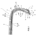
- Fig.1. is a sectional view showing an embodiment of the present invention
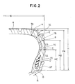
- Fig.2. is a schematic sectional view thereof
- Fig.3 is a diagram showing the thickness distribution of working examples of the present invention and reference examples and
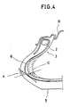
- Fig.4 is a sectional view showing the deformation of the
tread 5. - In the Figures, the safety tyre 1 is formed as a 255/40
ZR 17 tyre. - The tyre 1 has bead
portions 3 each provided with abead core 2, asidewall portion 4 extending radially outwardly from eachbead portion 3, and atread portion 5 extending between the upper ends of the sidewall portions to form a toroidal shape. - The tyre comprises a
carcass 6 having a main portion extending between thebead portions 3 through thesidewall portions 4 and thetread portion 5, a belt 7 disposed radially outside thecarcass 6 in the tread portion, and asidewall reinforcing layer 10 of approximately crescent shape disposed inside thecarcass 6 in each sidewall portion. In this embodiment, the tyre 1 was designed for high speed passenger cars, and the aspect ratio thereof, that is, the ration H/W of the tyre sectional height H to the tyre width W is not more than 50% being in fact 40%. - The
carcass 6 is turned up around the bead cores from the axially inside to the outside thereof to form turned up portions. The carcass has twoplies 6A, 6B of cords arranged radially at an angle of 60 to 90 degrees to the equator of the tyre, and steel cords as well as organic fibre cords such as rayon, polyester, nylon, aromatic polyamide, and the like can be used for the carcass cords. - The belt 7 disposed in the tread portion is composed of an axially inner
wide ply 7A and an outernarrow ply 7B, which consist of parallel cords arranged at a relatively small angle to the equator of the tyre so that the plies cross each other. For the belt cords, steel cords or high modulus organic fibre cords such as aromatic polyamide can be preferably used, but low modulus cords such as nylon, polyester or rayon may be used together therewith. When organic cords having a relatively smaller modulus are used, they may allow the belt to follow up deformation of thecarcass 6 while maintaining the hoop effect. - Further, a
breaker cushion 9 made of soft rubber is disposed between each edge of the belt and the carcass. - Further, on the radially outer surface of the belt 7,
bands 8 are disposed. Thebands 9 consist of a full width outsideband 8B and a pair of narrower edge insidebands 8A. - Each of the
inside bands 8A is extended axially inwardly from a position axially outwardly of each of the axially outer edges of the belt 7, and terminate to leave between the axially inner edges of the inside bands, a space having about 1/2 width of the tread width. - The
outside band 8B extends all over the width of thetread 5 to cover the belt 7 and the edges are substantially aligned with the axially outer edges of the inside bands. - Both the
bands - As mentioned above, in each of the
sidewall portions 4, asidewall reinforcing layer 10 is disposed inside the carcass. - As the carcass cord has a tensile rigidity more than ten times the rigidity of the sidewall rubber, if the sidewall portions are deformed in a deflated state by a load as shown in Fig.4, the bent part is subjected to both tensile strain and compressive strain on the axially outer side and inner side of the neutral carcass cords, respectively. Such compressive strain is carried by the sidewall reinforcing later 10, being a relatively hard material so as to enable the tyre to run even when deflated.
- For this purpose, the thickness of the
sidewall reinforcing layer 10 is a maximum in themid-sidewall portion 10A which receives a large compressive strain when deflated, and in the radially outwardlyportion 10B andinward portion 10C the thickness is decreased radially outwardly and inwardly respectively, so that the sectional shape of the sidewall reinforcing layer becomes a crescent shape, thereby preventing a decline in the tyre characteristics due to increase in the weight. - The
sidewall reinforcing layer 10 in this embodiment has a three layered structure where the axially inside layer A1 and the outside layer A3 are formed thinner than the intermediate layer A2, and the inside and outside layers are made of a relatively soft rubber having a Shore A of 50 to 70 degrees and a 100% modulus of 10 to 30 kgf/square cm, and the intermediate later is made of a relatively hard rubber having a Shore A hardness of 70 to 90 degrees and a 100% modulus of 30 to 70 kgf/square cm. - As a result, the inside layer A1 made of soft rubber can alleviate the local compressive strain caused on the inner surface of the intermediate layer A2 when running under a deflated condition, and cracks can be prevented to enhance the breakdown resistance.
- Although maximum bending and compressive strains act on this inside layer A1, breakdown can be prevented due to the use of a soft rubber which is excellent in crack resistance. The outside layer A3, disposed between the carcass and the intermediate layer A2, can avoid a reduction in ride comfort due to the use of the hard rubber intermediate later A2, and it is also effective for relaxing the shear strain which occurs between them, so that failure of the intermediate later A2 due to excessive generated heat is prevented.
- In the present invention, the point resides in the optimum distribution of the overall thickness of the sidewall portion, inclusive of the above mentioned carcass, rubber sidewalls and sidewall reinforcing layers.
- Accordingly, as shown in Fig.2 each sidewall portion has a minimum thickness at a portion E between an outer edge point A and a 65% height point B both located on each of the sidewall portions. Here the outer edge points A are defined as the axially outer edges of a ground contacting region (a) on the tread surface in a standard loaded state in which the tyre mounted on its regular rim R and inflated to its regular pressure is loaded with its regular load. The 65% height points B are defined as the positions at 65% height HB of the tyre section height H from the bead base b in the standard unloaded state when the tyre is mounted on its regular rim and inflated to its regular pressure and free of load (i.e. HB=0.65H). More specifically, the region defined between the outer edge point A and the 65% height point B (hereinafter referred to as the first region) does not contact the ground in normal running, and this region is located near the ground contacting surface (a), therefore it is desired to decrease the thickness to lower the heat generation in order to enhance the high speed durability performance. Such an arrangement also leads to a decrease in the vertical stiffness, thereby improving ride comfort and steering performance. Accordingly, the minimum thickness position E must be formed between the outer edge point A and the 65% height point B. Further, the first region contacts the road surface when running in a deflated state, and therefore from this viewpoint, too, it is evident that the increase of thickness of the first region does not contribute to the enhancement in the run flat performance.
- Furthermore, in the pneumatic safety tyre 1, the overall thickness is gradually increased in the region S2 from the minimum thickness E to the 65% height point B. As a result of avoiding an abrupt change in the sidewall thickness, stress concentration is prevented, and gradually increasing the vertical stiffness toward the 65% height point B, the runflat performance and the impact absorbing performance in normal running are improved.
- The height HA at the outer edge point A is generally between 82 to 98% of the sectional height H.
- The difference between the thickness TA at the outer edge point A and the thickness GB at the 65% height point B is set to be not more than 5% of the maximum tyre section width W formed between the maximum width point C in the above explained standard unloaded state. More preferably it is set within 3.5% of the maximum width W, so that a desirable overall thickness distribution is obtained. Meanwhile, the thickness TA may be set either larger or smaller than the 65% height point thickness TB, within the above range.
- The minimum thickness TE is set to be about 65 to 85% of the thickness TB at the 65% height point.
- Furthermore, in the tyre of the above mentioned size of this embodiment, the difference (TB-TE) of the 65% height point, thickness TB and the minimum thickness TE are set in a range of 2.0 to 5.0mm, and the minimum thickness TE is not less than 10 mm and not more than 13 mm.
- If the difference (TB-TE) is less than 2.0mm the minimum thickness TE becomes excessive or the 65% height point thickness TB becomes too small. If exceeding 5mm, the reverse effects are caused, and it is known that any desirable thickness distribution is not obtained in either case.
- Besides, if the minimum thickness TE is less than 10mm, the load bearing capacity of the tyre drops, and if exceeding 13mm, the generation of heat in the area increases, and the durability may be sacrificed.
- What is more, in a third region S3 from the 65% height point B to the maximum width point C in the standard unloaded state, the sidewall thickness is gradually increased from the point B to the point C because the deformation of the sidewall portions when deflated is largest in the vicinity of the maximum width point C. As a result the deformation is restrained, and the run flat performance is enhanced.
- Furthermore, the thickness TC at the maximum width point C is set to be not less than 4.5% and not more than 9% of the tyre maximum width W. This is the range of withstanding the bending stress, neither excessively nor insufficiently, during run flat running.
- In a fourth region S4 from the maximum width point C to a point D at which the bead portion starts to contact with a rim flange RF of the regular R, the thickness is increased from the former to the later.
- The thickness TD at the contact point D is set to be not less than 5% and not more than 10% of the tyre maximum width W.
- Furthermore, in the tyre of the tyre size of 225/40ZR17, the difference (TD-TC) in thickness between the contact point D and the maximum width C is not less than 2.0mm and not more than 5.0mm.
- In the portion around the upper edge of the rim flange TF, a large bending deformation is likely to occur when running in a flat condition, and accordingly the heat generation is increased, and damages such as ply separation are likely to occur, thereby tending to spoil the run flat performance.
- Accordingly, in order to prevent damage of the bead portion, the thickness TD at the contact point D is increased as mentioned above, whereby the run flat performance can be enhanced.
- Still more, in the tyre 1, between each of the
bead cores 2 and thecarcass 6, abead reinforcing layer 12 is disposed to prevent abrasion of the bead core or carcass ply due to movement of thecarcass 6 accompanying deformation of the tyre, and further, above thebead core 2, abead apex 13 extending taperingly radially outwardly is disposed between the carcass main portion and each of the turned up portions and inside thebead reinforcing layer 12, so as to increase the rigidity of thebead 3. - The bead apexes 1 help to keep the deformed shape of the portion of the lower sidewall above the bead in a specified standard curved shape. For this reason, the
bead apex 9 is made of a relatively hard rubber having a Shore A hardness of 74 to 95 degrees. - Each of the
bead portions 3 is further provided in the axially innermost portion with a toe strip made of hard rubber to form abead toe 14 which projects radially inwardly from the bead base line L. The bead base is provided with aconvex hump groove 15 located immediately axially outside thetoe 14. - Also, a
rim chafer 19 to prevent chafe of the bead by the rim R is disposed to extend from the axially inside of the bead portion toward the axially outside along the profile of thebead toe 14 and thehump groove 15. - On the other hand, the rim R is provided at each side with
annular groove 16 into which thebead toe 14 is fitted and ahump 17 which fitted into thehump groove 15. By the engagement therebetween, the bead portions are seated on the rim R safely preventing the tyre from being dislocated from the rim when deflated. - Incidentally, such a toe and a hump groove may be disposed at either both or one of the
beads 3. - Test tyres of 255/40 ZR17 size were experimentally fabricated according to the specification given in Table 1 and the structure shown in Fig.1.
- In Working example 1, the thickness TC at the maximum width point C was 5.7% of the maximum width W of the tyre, and the thickness was gradually increased from the minimum thickness point E to the contact point D. In Working Examples 2, the thickness was almost uniform from the 65% height point B to the maximum width point C. The thickness was gradually increased from the maximum width C to the contact point D.
- By contrast, in Reference 1, the maximum thickness portion was formed between the outer edge point of the ground contacting region S and the 65% height point B. In
Reference 2, the thickness distribution was similar toreference 2, but the thickness was reduced as compared with Reference 1. InReference 3, the thickness distribution was further decreased. - Those thickness distribution of the test tyres are summarised in Fig.3.
- Each test tyre was mounted on a rum R having the structure shown in Fig.1. The rim width was 10 inches.
- The assemblies were mounted on four wheels of a 5000cc automobile, which was run at 100 km/h with one wheel deflated to zero to simulate a puncture state, and then the distance until the deflated tyre was broken was measured.
- The results are shown in Table 1. As apparent from table 1, the run flat performance was largely improved by the invention.
- Furthermore, the tyres were tested for high speed inflated durability performance using an indoor drum tester.
- Setting the internal pressure ar 3.2 kg/square cm, the load at 525 kg, the camber angle at 1 degree and the rim size at 10 x 17, the rotating speed was increased from 250 km/h in 10km/h intervals every 20 minutes. The speed at which a breakdown occurred, and the time (minutes) to reach the breakdown at that speed are shown in table 1, from which it was shown that the tyre of Examples 1 and 2 were both excellent in high speed durability.
- On the contrary, Reference 1 having the maximum thickness between the outer edge point A and the 65% height point B was inferior in high speed durability.
- Moreover, running an actual car on a circuit course, the tyres were tested to check and assess any steering performance loss. The results of this are shown in Table 1 using an index based on the assumption that
Reference 3 was 100. The larger the index, the better was the result. - As apparent from the test results, the tyres of Examples 1 and 2 maintained an excellent steering performance the same as in the conventional tyre, in spite of their superior run flat performance.
- As described above, in the pneumatic safety tyres according to the present invention, as the distribution of the sidewall thickness inclusive of the sidewall reinforcing layer thickness, is optimised while providing a minimum thickness position between each of the outer edge point A of the ground contacting region on the tread surface and the 65% height point B, the run flat performance can be remarkably improved without sacrificing the high speed durability performance and the steering performance.
TABLE 1 Ex.1 Ex.2 Ref.1 Ref.2 Ref.3 Thickness TA (mm) 11.0 10.5 13.8 13.6 11.5 TB (mm) 13.2 12.8 15.5 11.8 10.8 TC (mm) 15.5 13.3 14.5 11.0 11.0 TD (mm) 17.6 16.2 15.7 14.7 15.3 TE (mm) 10 9.8 17.0 14.5 12.5 Running distance (km) 98 85 67 33 21 High speed durability 330 km/ h 9 min.350 km/ h 5 min.290 km/ h 6 min.320 km/h 18 min. 330 km/ h 15 min.Steering stability 99 101 91 97 100
Claims (5)
Applications Claiming Priority (2)
| Application Number | Priority Date | Filing Date | Title |
|---|---|---|---|
| JP302977/88 | 1988-11-30 | ||
| JP63302977A JPH02147417A (en) | 1988-11-30 | 1988-11-30 | Pneumatic safety tire |
Publications (3)
| Publication Number | Publication Date |
|---|---|
| EP0371755A2 true EP0371755A2 (en) | 1990-06-06 |
| EP0371755A3 EP0371755A3 (en) | 1991-01-16 |
| EP0371755B1 EP0371755B1 (en) | 1994-01-05 |
Family
ID=17915443
Family Applications (1)
| Application Number | Title | Priority Date | Filing Date |
|---|---|---|---|
| EP89312350A Expired - Lifetime EP0371755B1 (en) | 1988-11-30 | 1989-11-28 | Pneumatic safety tyre |
Country Status (6)
| Country | Link |
|---|---|
| US (1) | US5058646A (en) |
| EP (1) | EP0371755B1 (en) |
| JP (1) | JPH02147417A (en) |
| AU (1) | AU631384B2 (en) |
| CA (1) | CA2003756C (en) |
| DE (1) | DE68912097T2 (en) |
Cited By (15)
| Publication number | Priority date | Publication date | Assignee | Title |
|---|---|---|---|---|
| EP0456437A2 (en) * | 1990-05-07 | 1991-11-13 | Sumitomo Rubber Industries Limited | Safety tyre |
| AU625426B2 (en) * | 1989-09-08 | 1992-07-09 | Yokohama Rubber Co., Ltd., The | Run-flat pneumatic radial tire |
| US5217549A (en) * | 1991-04-04 | 1993-06-08 | Bridgestone/Firestone, Inc. | Pneumatic safety tire |
| EP0545681A1 (en) * | 1991-12-05 | 1993-06-09 | Sumitomo Rubber Industries Limited | Pneumatic safety tyre |
| US5263526A (en) * | 1992-09-30 | 1993-11-23 | The Goodyear Tire & Rubber Company | Pneumatic tire having specified bead structure |
| US5280817A (en) * | 1991-10-07 | 1994-01-25 | The Goodyear Tire & Rubber Company | Radial pneumatic tire having contoured zones in the sidewalls |
| US5368082A (en) * | 1992-09-30 | 1994-11-29 | The Goodyear Tire & Rubber Company | Radial ply pneumatic tire |
| WO1995003945A1 (en) * | 1993-07-30 | 1995-02-09 | Continental Aktiengesellschaft | Vehicle tyre |
| US5464899A (en) * | 1992-12-30 | 1995-11-07 | Bridgestone Corporation | High modulus low hysteresis rubber compound for pneumatic tires |
| US5685927A (en) * | 1992-09-30 | 1997-11-11 | The Goodyear Tire & Rubber Company | Run-flat tire with wet handling design |
| WO2000059741A1 (en) * | 1999-04-02 | 2000-10-12 | Sumitomo Rubber Industries, Ltd. | Pneumatic tire |
| EP1160101A2 (en) * | 2000-06-01 | 2001-12-05 | The Goodyear Tire & Rubber Company | Variable stiffness wedge insert for runflat tire |
| EP1388436A1 (en) | 2002-08-09 | 2004-02-11 | The Goodyear Tire & Rubber Company | Ruflat tire having sidewall thickness for optimized ride comfort |
| US7587933B2 (en) | 2004-03-01 | 2009-09-15 | Bridgestone Corporation | Process for repairing punctured pneumatic tire in tire-rim assembly and repairing system |
| EP2228236A1 (en) * | 2007-11-26 | 2010-09-15 | Sumitomo Rubber Industries, Ltd. | Pneumatic tire for motocross |
Families Citing this family (28)
| Publication number | Priority date | Publication date | Assignee | Title |
|---|---|---|---|---|
| US5711829A (en) * | 1990-09-25 | 1998-01-27 | Michelin Recherche Et Technique S.A. | Three- belt tire |
| EP0542252B1 (en) * | 1991-11-15 | 1996-06-05 | PIRELLI COORDINAMENTO PNEUMATICI S.p.A. | Self-bearing tyre for motor-vehicle wheels incorporating elastic-support inserts in the sidewalls |
| DE69418563T2 (en) * | 1993-10-12 | 1999-11-18 | Bridgestone Corp | Vulcanizing mold for tires |
| US5871601A (en) * | 1995-06-26 | 1999-02-16 | Bridgestone Corporation | Pneumatic radial tire with load bearing rubber reinforcing layer |
| US6026878A (en) * | 1997-05-29 | 2000-02-22 | The Goodyear Tire & Rubber Company | Inextensible high temperature resistant tire |
| JP4390932B2 (en) * | 1998-11-19 | 2009-12-24 | 株式会社ブリヂストン | Pneumatic tire |
| US6695025B1 (en) * | 1999-05-18 | 2004-02-24 | The Goodyear Tire & Rubber Company | Runflat tire construction with ply cords having a variable modulus of elasticity |
| US6494242B2 (en) | 1999-05-27 | 2002-12-17 | Michelin Recherche Et Technique | Runflat tire having optimized carcass path |
| US6843293B1 (en) * | 1999-12-16 | 2005-01-18 | The Goodyear Tire & Rubber Company | Variable-stiffness wedge insert for runflat tires |
| US6443201B1 (en) * | 2000-06-13 | 2002-09-03 | The Goodyear Tire & Rubber Company | Pneumatic tire with extended load carrying capacity |
| DE10343599A1 (en) * | 2003-09-20 | 2005-04-28 | Continental Ag | Vehicle tires |
| US7448422B2 (en) * | 2004-04-22 | 2008-11-11 | The Goodyear Tire & Rubber Company | Pneumatic run-flat tire |
| WO2006071230A1 (en) * | 2004-12-29 | 2006-07-06 | Michelin Recherche Et Technique S.A. | Extended-mobility tire comprising an insert having two zones with substantially different sizes |
| JP4523918B2 (en) * | 2006-01-25 | 2010-08-11 | 住友ゴム工業株式会社 | Run flat tire |
| JP4971700B2 (en) * | 2006-06-26 | 2012-07-11 | 住友ゴム工業株式会社 | Run flat tire |
| JP2009126409A (en) * | 2007-11-26 | 2009-06-11 | Sumitomo Rubber Ind Ltd | Run flat tire |
| EP2792507B1 (en) * | 2009-03-11 | 2016-11-09 | Bridgestone Corporation | Run-flat tire |
| JP5357945B2 (en) * | 2011-10-12 | 2013-12-04 | 住友ゴム工業株式会社 | Run-flat tire and its mounting method |
| JP5962481B2 (en) * | 2012-02-08 | 2016-08-03 | 横浜ゴム株式会社 | Pneumatic tire |
| FR2992586B1 (en) * | 2012-06-28 | 2015-10-30 | Michelin & Cie | PNEUMATIC CARCASS REINFORCEMENT FOR AGRICULTURAL VEHICLE |
| CN102922950B (en) * | 2012-11-13 | 2014-11-05 | 江苏通用科技股份有限公司 | Reinforcing type liner layer structure |
| JP6317165B2 (en) * | 2014-04-14 | 2018-04-25 | 株式会社ブリヂストン | Run flat tire |
| CN106457896B (en) * | 2014-06-17 | 2018-09-21 | 横滨橡胶株式会社 | Pneumatic tire |
| US10086658B2 (en) * | 2014-10-29 | 2018-10-02 | Bridgestone Corporation | Run-flat tire |
| JP6455095B2 (en) * | 2014-11-21 | 2019-01-23 | 横浜ゴム株式会社 | Pneumatic tire |
| DE102015209061A1 (en) * | 2015-05-18 | 2016-11-24 | Continental Reifen Deutschland Gmbh | Pneumatic vehicle tires with emergency running properties |
| JP6939560B2 (en) * | 2016-10-06 | 2021-09-22 | 横浜ゴム株式会社 | Bias tire |
| JP7187882B2 (en) * | 2018-08-09 | 2022-12-13 | 住友ゴム工業株式会社 | run flat tires |
Citations (5)
| Publication number | Priority date | Publication date | Assignee | Title |
|---|---|---|---|---|
| FR2082073A5 (en) * | 1970-03-01 | 1971-12-10 | Michelin & Cie | |
| FR2137339A1 (en) * | 1971-05-18 | 1972-12-29 | Michelin & Cie | |
| FR2215331A1 (en) * | 1973-01-29 | 1974-08-23 | Kleber Colombes | |
| EP0128852A2 (en) * | 1983-06-06 | 1984-12-19 | The Goodyear Tire & Rubber Company | A pneumatic tire |
| US4779658A (en) * | 1986-05-28 | 1988-10-25 | Bridgestone Corporation | Pneumatic safety tire |
Family Cites Families (10)
| Publication number | Priority date | Publication date | Assignee | Title |
|---|---|---|---|---|
| GB1436725A (en) * | 1972-06-21 | 1976-05-26 | Bridgestone Tire Co Ltd | Pneumatic safety tyre |
| FR2261888B1 (en) * | 1974-02-26 | 1976-12-10 | Kleber Colombes | |
| JPS5131632A (en) * | 1974-09-10 | 1976-03-17 | Hitachi Shipbuilding Eng Co | IGATA |
| JPS5131643A (en) * | 1974-09-11 | 1976-03-17 | Kawasaki Steel Co | TSUGITEKORITSUNOTAKAI T GATAKOSHUHAYOSETSUTSUGITE NO SEIZOHOHO |
| US4142567A (en) * | 1975-08-06 | 1979-03-06 | Continental Gummi-Werke Aktiengesellschaft | Pneumatic vehicle tire |
| PT68279A (en) * | 1977-08-15 | 1978-08-01 | Goodyear Tire & Rubber | Pneumatic tire and pneumatic tire mounted on a rim |
| JPS579969A (en) * | 1980-06-17 | 1982-01-19 | Wako Seisakusho Kk | Production of metal spherical water tank |
| DE3024983C2 (en) * | 1980-07-02 | 1989-08-10 | Webasto-Werk W. Baier GmbH & Co, 8035 Gauting | Method and circuit arrangement for determining an amount of preheating energy |
| JPS5946801A (en) * | 1982-09-10 | 1984-03-16 | Mitsutoyo Mfg Co Ltd | Two-way touch sensor |
| JP2574816B2 (en) * | 1987-10-27 | 1997-01-22 | 住友ゴム工業 株式会社 | Safety tire |
-
1988
- 1988-11-30 JP JP63302977A patent/JPH02147417A/en active Pending
-
1989
- 1989-11-23 CA CA002003756A patent/CA2003756C/en not_active Expired - Fee Related
- 1989-11-27 US US07/441,556 patent/US5058646A/en not_active Expired - Fee Related
- 1989-11-28 AU AU45670/89A patent/AU631384B2/en not_active Ceased
- 1989-11-28 EP EP89312350A patent/EP0371755B1/en not_active Expired - Lifetime
- 1989-11-28 DE DE89312350T patent/DE68912097T2/en not_active Expired - Fee Related
Patent Citations (5)
| Publication number | Priority date | Publication date | Assignee | Title |
|---|---|---|---|---|
| FR2082073A5 (en) * | 1970-03-01 | 1971-12-10 | Michelin & Cie | |
| FR2137339A1 (en) * | 1971-05-18 | 1972-12-29 | Michelin & Cie | |
| FR2215331A1 (en) * | 1973-01-29 | 1974-08-23 | Kleber Colombes | |
| EP0128852A2 (en) * | 1983-06-06 | 1984-12-19 | The Goodyear Tire & Rubber Company | A pneumatic tire |
| US4779658A (en) * | 1986-05-28 | 1988-10-25 | Bridgestone Corporation | Pneumatic safety tire |
Cited By (28)
| Publication number | Priority date | Publication date | Assignee | Title |
|---|---|---|---|---|
| AU625426B2 (en) * | 1989-09-08 | 1992-07-09 | Yokohama Rubber Co., Ltd., The | Run-flat pneumatic radial tire |
| US5131445A (en) * | 1989-09-08 | 1992-07-21 | The Yokohama Rubber Co., Ltd. | Run-flat pneumatic radial tire |
| EP0456437A3 (en) * | 1990-05-07 | 1992-03-25 | Sumitomo Rubber Industries Limited | Safety tyre |
| EP0456437A2 (en) * | 1990-05-07 | 1991-11-13 | Sumitomo Rubber Industries Limited | Safety tyre |
| US5217549A (en) * | 1991-04-04 | 1993-06-08 | Bridgestone/Firestone, Inc. | Pneumatic safety tire |
| US5280817A (en) * | 1991-10-07 | 1994-01-25 | The Goodyear Tire & Rubber Company | Radial pneumatic tire having contoured zones in the sidewalls |
| EP0545681A1 (en) * | 1991-12-05 | 1993-06-09 | Sumitomo Rubber Industries Limited | Pneumatic safety tyre |
| AU681561B2 (en) * | 1992-09-30 | 1997-08-28 | Goodyear Tire And Rubber Company, The | A radial ply pneumatic tire |
| US6263935B1 (en) | 1992-09-30 | 2001-07-24 | The Goodyear Tire & Rubber Company | Radial ply pneumatic runflat tire |
| US5639320A (en) * | 1992-09-30 | 1997-06-17 | Oare; Thomas Reed | Radial ply pneumatic tire |
| US5263526A (en) * | 1992-09-30 | 1993-11-23 | The Goodyear Tire & Rubber Company | Pneumatic tire having specified bead structure |
| US5679188A (en) * | 1992-09-30 | 1997-10-21 | The Goodyear Tire & Rubber Company | Pneumatic tire having specified bead structure |
| US5685927A (en) * | 1992-09-30 | 1997-11-11 | The Goodyear Tire & Rubber Company | Run-flat tire with wet handling design |
| US5851324A (en) * | 1992-09-30 | 1998-12-22 | The Goodyear Tire & Rubber Company | Radial ply pneumatic tire |
| US5368082A (en) * | 1992-09-30 | 1994-11-29 | The Goodyear Tire & Rubber Company | Radial ply pneumatic tire |
| US5464899A (en) * | 1992-12-30 | 1995-11-07 | Bridgestone Corporation | High modulus low hysteresis rubber compound for pneumatic tires |
| US5494091A (en) * | 1992-12-30 | 1996-02-27 | Bridgestone Corporation | High modulus low hysteresis rubber compound for pneumatic tires |
| US5494958A (en) * | 1992-12-30 | 1996-02-27 | Bridgestone Corporation | High modulus low hysteresis rubber compound for pneumatic tires |
| WO1995003945A1 (en) * | 1993-07-30 | 1995-02-09 | Continental Aktiengesellschaft | Vehicle tyre |
| WO2000059741A1 (en) * | 1999-04-02 | 2000-10-12 | Sumitomo Rubber Industries, Ltd. | Pneumatic tire |
| US6457503B1 (en) | 1999-04-02 | 2002-10-01 | Sumitomo Rubber Industries, Ltd. | Pneumatic tire |
| US6651714B2 (en) | 1999-04-02 | 2003-11-25 | Sumitomo Rubber Industries, Ltd. | Pneumatic tire |
| EP1160101A2 (en) * | 2000-06-01 | 2001-12-05 | The Goodyear Tire & Rubber Company | Variable stiffness wedge insert for runflat tire |
| EP1160101A3 (en) * | 2000-06-01 | 2003-07-16 | The Goodyear Tire & Rubber Company | Variable stiffness wedge insert for runflat tire |
| EP1388436A1 (en) | 2002-08-09 | 2004-02-11 | The Goodyear Tire & Rubber Company | Ruflat tire having sidewall thickness for optimized ride comfort |
| US7587933B2 (en) | 2004-03-01 | 2009-09-15 | Bridgestone Corporation | Process for repairing punctured pneumatic tire in tire-rim assembly and repairing system |
| EP2228236A1 (en) * | 2007-11-26 | 2010-09-15 | Sumitomo Rubber Industries, Ltd. | Pneumatic tire for motocross |
| EP2228236A4 (en) * | 2007-11-26 | 2014-01-22 | Sumitomo Rubber Ind | Pneumatic tire for motocross |
Also Published As
| Publication number | Publication date |
|---|---|
| EP0371755B1 (en) | 1994-01-05 |
| CA2003756A1 (en) | 1990-05-31 |
| DE68912097D1 (en) | 1994-02-17 |
| DE68912097T2 (en) | 1994-04-28 |
| AU4567089A (en) | 1990-06-07 |
| EP0371755A3 (en) | 1991-01-16 |
| AU631384B2 (en) | 1992-11-26 |
| CA2003756C (en) | 1996-02-20 |
| JPH02147417A (en) | 1990-06-06 |
| US5058646A (en) | 1991-10-22 |
Similar Documents
| Publication | Publication Date | Title |
|---|---|---|
| EP0371755B1 (en) | Pneumatic safety tyre | |
| US6247512B1 (en) | Tire having tread portion with rubber to control wear | |
| EP1481822B1 (en) | Pneumatic radial tire | |
| EP2033814B1 (en) | Pneumatic tire | |
| EP3482977B1 (en) | Heavy-duty pneumatic tire | |
| EP1683654B1 (en) | Runflat tire | |
| EP1872972B1 (en) | Heavy duty pneumatic tire | |
| US11331963B2 (en) | Run-flat tire | |
| EP0844110B1 (en) | Pneumatic tyre | |
| EP0790143A1 (en) | Pneumatic radial tyre | |
| EP0314445A2 (en) | Safety tyre | |
| EP3482976B1 (en) | Heavy-duty pneumatic tire | |
| EP2186656B9 (en) | Pneumatic tire | |
| EP3202594B1 (en) | Pneumatic tire | |
| EP1201464B1 (en) | Pneumatic radial tires | |
| EP1584494A2 (en) | Pneumatic run-flat tire | |
| EP0298673A2 (en) | Radial tyre | |
| EP0736400B1 (en) | Heavy duty pneumatic radial tires | |
| EP1199192B1 (en) | Pneumatic tire | |
| EP3173257B1 (en) | Run-flat tire | |
| US20030111152A1 (en) | Pneumatic tire bead area construction for improved chafer cracking resistance during run-flat operation | |
| EP0545681B1 (en) | Pneumatic safety tyre | |
| EP0640496B1 (en) | Pneumatic tyre | |
| EP0409518A2 (en) | Motorcycle tyre | |
| JPH07144516A (en) | Tire for high speed and heavy load |
Legal Events
| Date | Code | Title | Description |
|---|---|---|---|
| PUAI | Public reference made under article 153(3) epc to a published international application that has entered the european phase |
Free format text: ORIGINAL CODE: 0009012 |
|
| AK | Designated contracting states |
Kind code of ref document: A2 Designated state(s): CH DE FR GB IT LI |
|
| PUAL | Search report despatched |
Free format text: ORIGINAL CODE: 0009013 |
|
| AK | Designated contracting states |
Kind code of ref document: A3 Designated state(s): CH DE FR GB IT LI |
|
| 17P | Request for examination filed |
Effective date: 19901221 |
|
| 17Q | First examination report despatched |
Effective date: 19920805 |
|
| GRAA | (expected) grant |
Free format text: ORIGINAL CODE: 0009210 |
|
| AK | Designated contracting states |
Kind code of ref document: B1 Designated state(s): CH DE FR GB IT LI |
|
| ITF | It: translation for a ep patent filed |
Owner name: ING. C. GREGORJ S.P.A. |
|
| REF | Corresponds to: |
Ref document number: 68912097 Country of ref document: DE Date of ref document: 19940217 |
|
| ET | Fr: translation filed | ||
| PLBE | No opposition filed within time limit |
Free format text: ORIGINAL CODE: 0009261 |
|
| STAA | Information on the status of an ep patent application or granted ep patent |
Free format text: STATUS: NO OPPOSITION FILED WITHIN TIME LIMIT |
|
| 26N | No opposition filed | ||
| PGFP | Annual fee paid to national office [announced via postgrant information from national office to epo] |
Ref country code: FR Payment date: 19981110 Year of fee payment: 10 |
|
| PGFP | Annual fee paid to national office [announced via postgrant information from national office to epo] |
Ref country code: GB Payment date: 19981204 Year of fee payment: 10 |
|
| PGFP | Annual fee paid to national office [announced via postgrant information from national office to epo] |
Ref country code: DE Payment date: 19981207 Year of fee payment: 10 |
|
| PGFP | Annual fee paid to national office [announced via postgrant information from national office to epo] |
Ref country code: CH Payment date: 19981210 Year of fee payment: 10 |
|
| PG25 | Lapsed in a contracting state [announced via postgrant information from national office to epo] |
Ref country code: GB Free format text: LAPSE BECAUSE OF NON-PAYMENT OF DUE FEES Effective date: 19991128 |
|
| PG25 | Lapsed in a contracting state [announced via postgrant information from national office to epo] |
Ref country code: LI Free format text: LAPSE BECAUSE OF NON-PAYMENT OF DUE FEES Effective date: 19991130 Ref country code: CH Free format text: LAPSE BECAUSE OF NON-PAYMENT OF DUE FEES Effective date: 19991130 |
|
| REG | Reference to a national code |
Ref country code: CH Ref legal event code: PL |
|
| GBPC | Gb: european patent ceased through non-payment of renewal fee |
Effective date: 19991128 |
|
| PG25 | Lapsed in a contracting state [announced via postgrant information from national office to epo] |
Ref country code: FR Free format text: LAPSE BECAUSE OF NON-PAYMENT OF DUE FEES Effective date: 20000731 |
|
| PG25 | Lapsed in a contracting state [announced via postgrant information from national office to epo] |
Ref country code: DE Free format text: LAPSE BECAUSE OF NON-PAYMENT OF DUE FEES Effective date: 20000901 |
|
| REG | Reference to a national code |
Ref country code: FR Ref legal event code: ST |
|
| PG25 | Lapsed in a contracting state [announced via postgrant information from national office to epo] |
Ref country code: IT Free format text: LAPSE BECAUSE OF NON-PAYMENT OF DUE FEES;WARNING: LAPSES OF ITALIAN PATENTS WITH EFFECTIVE DATE BEFORE 2007 MAY HAVE OCCURRED AT ANY TIME BEFORE 2007. THE CORRECT EFFECTIVE DATE MAY BE DIFFERENT FROM THE ONE RECORDED. Effective date: 20051128 |