EP0373820A2 - Filter device employing a holographic element - Google Patents
Filter device employing a holographic element Download PDFInfo
- Publication number
- EP0373820A2 EP0373820A2 EP89312696A EP89312696A EP0373820A2 EP 0373820 A2 EP0373820 A2 EP 0373820A2 EP 89312696 A EP89312696 A EP 89312696A EP 89312696 A EP89312696 A EP 89312696A EP 0373820 A2 EP0373820 A2 EP 0373820A2
- Authority
- EP
- European Patent Office
- Prior art keywords
- filter
- hologram
- optical radiation
- band
- providing
- Prior art date
- Legal status (The legal status is an assumption and is not a legal conclusion. Google has not performed a legal analysis and makes no representation as to the accuracy of the status listed.)
- Withdrawn
Links
Images
Classifications
-
- G—PHYSICS
- G02—OPTICS
- G02B—OPTICAL ELEMENTS, SYSTEMS OR APPARATUS
- G02B5/00—Optical elements other than lenses
- G02B5/32—Holograms used as optical elements
-
- G—PHYSICS
- G02—OPTICS
- G02B—OPTICAL ELEMENTS, SYSTEMS OR APPARATUS
- G02B5/00—Optical elements other than lenses
- G02B5/20—Filters
- G02B5/203—Filters having holographic or diffractive elements
Definitions
- This invention relates to filter devices. More particularly this invention relates to filter devices employing a holographic element.
- night imaging system refers to an optical system capable of intensifying images viewed under low light levels, e.g. nighttime conditions. Night imaging systems are popularly employed in aviation applications.
- An example of a night imaging system would be the ANVIS system (Aviator's Night Vision Imaging System), which is produced by Hughes Optical Products, Inc.
- the ANVIS system is a helmet-mounted unity power image intensified binocular that enhances vision under low light level conditions.
- a discussion of the ANVIS system can be found in Efkeman, Jenkins, Development of an Aviator's Night Vision Imaging System (ANVIS) , presented July 28-August 1, 1988, SPIE International Technical Symposium and Exhibit.
- unfiltered night imaging systems such as an unfiltered ANVIS system
- ANVIS unfiltered night imaging systems
- the panel lights in many cockpits tend to overdrive the image intensifier in the imaging system.
- Minus-blue filters typically are suitable for filtering cockpit lighting, while still failing to substantially interfere with the viewing of outside imagery.
- a minus-blue filter tends to inhibit viewing of images from cathode ray tubes (CRT), such as those found in head-up display units. This is largely due to a high attenuation of green light, emitted from the CRT, caused by the minus-blue filter.
- the typical attenuation is of a magnitude that, when using minus-blue filters, the CRT has to be employed at such high intensity levels that a useful image is not easily obtained.
- a partially filtered imaging system be employed to reduce light transmission of a first wavelength, yet pass through light of a second wavelength.
- a partially filtered imaging system be employed to reduce glare from cockpit lights, yet pass through infrared radiation and green light from a CRT, to permit viewing of a head-up display image.
- One such imaging system might employ an input aperture having all but a small area which is covered by a filter.
- the filter is typically employed to reduce glare.
- the small unfiltered area would pass light from the head-up display image.
- a typical filter would be one such as a Schott BG-7B filter which is a broadband blue green transmitting filter. That filter typically has about a 60 nm transmission band.
- the head-up display transmits a more narrow band, i.e. about 20 nm, the relatively broad band of filters like the Schott BG-7B renders it unsuitable for many applications. That is, broader transmission bands of the filter introduce greater amounts of undesired light.
- a filter device and method of making the same is disclosed.
- Optical radiation filter means are provided for filtering radiation of a first predetermined range of wavelengths.
- Holographic means are provided for diffracting radiation of a second predetermined range of wavelengths.
- the optical radiation means is coupled with the holographic means.
- the device 10 of the present invention comprises holographic means 12 disposed in a spaced relationship with optical radiation filter means 14.
- the optical radiation filter means 14, having a predetermined thickness are provided for filtering incident radiation of at least a first predetermined range or band of wavelengths.
- the expression "optical radiation filter” refers to a filter or combination of filters capable of filtering radiation of a predetermined range or band of wavelengths, and is not intended to be limited to filtering visible light radiation.
- the holographic means 12, having a predetermined thickness are provided for diffracting radiation of at least a second predetermined range or band of wavelengths. Used in combination with each other, the optical radiation filter means and the holographic means transmit predetermined amounts of one or more predetermined wavelengths of radiation. Various results obtained by this unique combination have previously been unattainable using the present holographic means or optical radiation filter means singly.
- a filter device 10 suitable for applications such as in aircraft cockpits, which comprises a hologram 12 and an optical radiation filter 14 disposed in a spaced relationship.
- the spacing between the optical radiation filter 14 and the hologram 10 ranges from as little as about zero inches to a distance limited only by operating and/or equipment limitations.
- the optical radiation filter may be in contact with each other, or disposed in a system, such as an optical viewing system, so that they are separated by one or more suitable media, such as air.
- the filter device 10 of the present invention should preferably allow infrared radiation to pass unattenuated; filter substantially all cockpit light; and transmit at least at about 50% attenuation a narrow bandwidth of light of about 543 nm.
- optical radiation filter means 14 having first and second surfaces 16 and 18, respectively, are provided for filtering optical radiation of at least a first predetermined range or band of wavelengths.
- the optical radiation means comprise one or more ordinary band pass filters, i.e. optical radiation filters that filter light radiation of a predetermined range of wavelengths.
- the filter means provided is a narrow band pass filter, such as a Schott BG-7B. That filter exhibits greater than about 60% transmission over a range of wavelengths of about 530-560 nm; and transmits substantially all infrared radiation.
- the Schott BG-7B as described for use in the present embodiment, preferably has a thickness of about one-eighth inch.
- the thickness dimension may be varied to take into account various properties obtainable by varying filter thickness and will depend largely upon the application, and/or operating conditions, of the ultimate filter device 10.
- Optical radiation filter means 14 which are suitable for the use in the present devices also include, without limitation, known band-pass filters, such as narrow and/or broad band-pass filters, and may suitably be absorption and/or interference filters.
- known band-pass filters such as narrow and/or broad band-pass filters
- the filters employed in the methods and devices of the present invention may be selected from those filters listed in Table I.
- the characteristics of the filters are described according to their approximate x and y coordinate values as they would appear if plotted on a known C.I.E. chromaticity diagram, which diagram is described in detail in B. D. McMains, Recommendations for Color Limitation of Illuminated Devices Used in Connection with AN/AVS-6 Night Vision Goggles , presented October 19, 1983, SAE A-20A subcommittee -- meeting No. 52, which is hereby expressly incorporated by reference.
- C.I.E. chromaticity diagrams display the relative wavelengths and purity of colored light as generated by an equal energy source.
- the above optical radiation filter means 14 likely fail to filter some wavelengths of radiation, thereby rendering the filter means unsuitable for many applications.
- a filter singly such as the use of a Schott BG-7B filter singly, is less preferred because the Schott BG-7B tends to transmit too much undesired light having a wavelength of about 543 nm, thereby tending to overdrive the night imaging system's intensifier.
- holographic means having first and second surfaces 20 and 22 respectively are provided, such as by preparing holographic means, for use in combination with the optical radiation filter means 14.
- the optical radiation filter means 14 are coupled, i.e. combined with, the holographic means 12.
- the optical radiation filter means 14 can be coupled with the holographic means 12 so that the space maintained between them is as little as about zero inches.
- the holographic means 12 is provided for diffracting radiation of at least a second predetermined band of range or wavelengths. More particularly, when combined with the optical filter means 14, the holographic means 12 facilitates trimming or narrowing of the bandwidth of a source of incident light, as well as reducing the amount of transmission of such light to a predetermined level.
- the optical radiation filter means 14 is coupled with the holographic means 12 by adjoining the optical radiation filter means with the holographic means 12 using a suitable adhesive at an interface 24, defined by the second surface of the optical radiation filter means and the first surface of the holographic means.
- a suitable optical adhesive is Norland Optical Cement NOA 61, which is an ultraviolet curable polyurethane-containing compound.
- the second surface 18 of the optical radiation means is disposed adjacent and conterminous with the first surface 20 of the holographic means.
- a variety of combinations of optical filters and holograms are obtainable according to the methods and devices of the present invention.
- additional layers between said optical radiation means For instance, it is contemplated that a clear protective layer such as a clear gelatin layer, or other suitable layer, may be employed between the optical radiation means 14 and the holographic means 12.
- the holographic means 12, and optical radiation filter means 14, which are disposed in a spaced relationship with each other are separated for a predetermined distance by a suitable medium, such as air.
- the preferred holographic means 12 employed in the present invention is a reflection hologram, and more preferably a zero-angle reflection hologram. That is, the preferred holographic means is a hologram having an interference pattern 26 (i.e. fringes) recorded in the hologram substantially parallel to the first and second surfaces 20 and 22 of the hologram. The fringes are thus at approximately a zero degree angle with respect to the first and second surfaces of the hologram. It is appreciated, however, that fringes having different angular dispositions may be formed and used in the holograms according to the methods and devices of the present invention.
- other holographic means include without limitation reflection and/or transmission holograms of the type including volume holograms, surface holograms, phase holograms, and/or amplitude holograms.
- the preferred hologram 12 is substantially flat and the first and second surfaces 20 and 22 are substantially parallel to each other. With some basic modification to the methods of the present invention, it is also possible to produce a filter device on a curved substrate surface. Further, it is also within the contemplation of the methods and devices of the present invention that multiple layer holograms may be employed as holographic means. A description of such multiple layer holograms and method of preparing the same is disclosed in co-pending United States Patent Application "High Efficiency Holograms by Multiple-layer Holography", which is hereby expressly incorporated by reference.
- the fringes of the present preferred hologram are spaced at one or more predetermined distances with respect to each other and with respect to the first and second surfaces 20 and 22 of the hologram to reflect one or more predetermined range of wavelengths.
- the effect of such reflection is to reduce the transmission of radiation, such as light having a relatively narrow bandwidth, through the hologram.
- the fringe spacing employed in the methods and devices of the present invention may be varied to many suitable distances in order to affect the transmission of incident radiation.
- the fringes are preferably spaced to diffract light having wavelengths ranging from about 550nm to about 580nm.
- holographic means 12 can be provided to diffract a more narrow bandwidth of radiation than previously obtainable using an optical filter singly.
- Holographic means of the present preferred embodiment preferably has a thickness of about 0.001 inches.
- the ranges of wavelengths filtered by the devices of the present invention may be selected and varied to suit particular applications where selective transmission of one or more particular wavelengths is desired.
- the filter device 10 of the present invention thus takes advantage of relatively precise diffraction properties obtainable by using holograms to trim, e.g. "fine tune", an optical radiation filter, such as the Schott BG-7B, when, the hologram and the optical radiation filter are used in combination with each other.
- an optical radiation filter such as the Schott BG-7B
- a completed filter device 10, such as the one described above, which comprises an optical radiation filter in face-to-face combination with a hologram will preferably have a thickness of about one-eight (1/8) inches.
- device thickness can be varied by varying the thicknesses of the optical radiation filter 14 and/or the hologram 12, wherein by varying the thickness it is possible to vary the characteristics of the filter device 10.
- the spaced relationship maintained between the hologram and the optical radiation filter may be such that the hologram and optical radiation filter are separated for a predetermined distance by a suitable medium, such as air. This latter embodiment can be accomplished in any suitable manner, including fixably positioning the optical radiation filter at a predetermined distance from the hologram using suitable mechanical means.
- the completed optical filter device 10 can be fitted to a variety of imaging systems, such as an ANVIS system, using suitable fitting means such as a cover glass for the objective lens in that system.
- imaging systems such as an ANVIS system
- suitable fitting means such as a cover glass for the objective lens in that system.
- Filter devices 10 prepared according to the methods of the present invention may be employed in many applications where the transmission of a narrow band of radiation, such as light, of a relatively precise range of wavelengths is desired.
- the present filter devices may be employed in applications where transmission of a narrow band of light is desired in order to simulate monochromatic light.
- filters and holograms may optionally be employed, including, without limitation, filter combinations such as those comprising a narrow band interference filter and a holographic reflection filter; a broad band interference filter and a holographic reflection filter; a broad band absorption interference filter and a holographic reflection filter; or any other combination where it is desired to narrow the transmission range of a filter by a relatively small amount.
- devices of the present invention can be varied to accommodate operating conditions of various applications, and are not limited in scope to aircraft cockpit applications.
- devices of the present invention may be employed anywhere the filter device is desired to have a sharper cut-off than normal, and where the transmission is narrower than normal.
- the filter device 10 of the present invention preferably is prepared by providing an optical radiation filter 14 of a predetermined thickness, having a first surface 16 and a second surface 18, capable of filtering optical radiation of at least a first predetermined range of wavelengths; providing a hologram 12 of a predetermined thickness, having a first surface 20 and a second surface 22, capable of diffracting radiation of at least a second predetermined range of wavelengths; and coupling the first surface 20 of said hologram 12 with the second surface 18 of said optical radiation filter 14.
- optical radiation filters are suitable for employment in the methods and devices of the present invention and include, without limitation, narrow and/or broad band-pass filters; and may suitably be absorption and/or interference filters, or combinations thereof.
- the optical filter provided will have a thickness of about 1/8 inch.
- the filter should preferably be substantially flat, although it is appreciated that, in many applications, filters having a curvature may suitably be employed.
- the hologram is provided preferably by preparing a hologram according to any method capable of yielding preferred diffraction characteristics for the desired application.
- One preferred method of preparing a hologram for emplopment in the devices of the present invention is summarily described as the steps of processing an exposed interference pattern in a photosensitive layer, which layer has been coated on a suitable substrate, to form a hologram.
- the following is a more detailed description which makes reference, to a large extent, to a number of steps which are known in the art and are summarized in H. M. Smith, Principles of Holography , John Wiley and Sons, Inc., 2d ed. 1975; and H. M. Smith, Holographic Recording Materials , Springer Verlay, 1977, which are hereby expressly incorporated by reference.
- the hologram prepared according to the methods described herein is preferably a reflection-type hologram having substantially zero degree fringes. That is, the interference pattern recorded as the hologram is substantially parallel to the first and second surfaces 20 and 22 of the hologram 12.
- the holograms of the present invention preferably should be prepared to avoid producing noise holograms.
- Noise holograms which arise partly due to "air-glass" interface reflection, i.e. the reflection occuring during hologram exposure due partly to the interface between the recording medium and air.
- Noise holograms are undesirable for at least two reasons. First, reflection-type noise holograms typically generate an undesired reflection color for the hologram. Second, transmission type noise holograms tend to generate an undesirable rainbow-like blurring and distortion of imagery obtained using the hologram.
- a suitable holographic recording medium having a predetermined thickness is provided.
- the recording medium is substantially flat.
- the dimensions and shape of the recording medium are limited only by practical considerations, including manufacturing equipment and ultimate use for the completed hologram.
- the recording medium is prepared by coating a photosensitive layer, preferably a sensitized dichromated gelatin layer, onto a major surface of a suitable substrate.
- Various coating methods may be suitably employed and include cast coating, doctor blade coating, spray coating, dip coating, and resin coating.
- Suitable substrates include a front surfaced mirror in applications where it is preferred that the gelatin layer is ultimately peeled off.
- Other substrates may be employed and include without limitation, transparent substrates such as thin glass plates which are index matched to a mirror during subsequent holographic exposure steps, photographic grade mylar, polycarbonate, polyester, and cellulose acetate. Further, it is possible to employ the optical radiation filter 14 as the present substrate.
- a plurality of spacers should preferably be disposed on the major surface of the substrate.
- the spacers serve to support the preferred gelatin layer during exposure.
- Suitable spacers include glass beads in a urethane matrix, steel balls or the like.
- the spacers that are employed are separated from each other by a distance of about 0.040 inches.
- the spacers preferably support the layer and are index matched to the layer with a suitable index matching fluid such as mineral oil.
- suitable index matching fluids include, without limitation, xylene, and microscope immersion fluid.
- Alternate methods of avoiding production of noise holograms, such as those generated in part by air-glass interface reflection include, in addition to using the above method of index matching, coating the substrate with an antireflective (AR) coating; adding an antireflective coated cover glass which is itself index matched to the substrate; moving an AR-coated cover glass with respect to the substrate during holographic exposure as disclosed in United States Patent No. 4,458,977 which is hereby expressly incorporated by reference; using a suitable complex prism assembly to facilitate prevention of undesirable reflections from reaching the hologram; or using a scanning exposure laser beam with a beam diameter small enough to avoid the possibility that a reflected beam generated by an exposure beam will overlap (and interfere with) the primary beam generated by the exposure beam.
- AR antireflective
- a hologram is exposed in the recording medium using conventional methods to form holographic fringes 26.
- a suitable method of exposing holographic fringes is described in L. Solymar, D. J. Cook, Volume Holography and Volume Grating , Academic Press, 1981, which is hereby expressly incorporated by reference.
- a holographic exposure is preferably made using a substantially collimated laser light beam.
- the collimated beam comprises a first entering beam.
- a reflection caused by the first beam off a mirror, or other suitable reflective medium which is preferably associated with the substrate provides a second beam necessary for holographic recording.
- the beams are provided at one or more predetermined exposure levels.
- the preferred exposure level is about 150 millijoules/cm2.
- the beams are introduced into the recording medium at one or more predetermined angles of illumination.
- the angle of illumination is largely dependent on the particular dichromated gelatin being used and the wavelength of laser light being used. For example, for a standard 300 bloom porkskin gelatin and 514.5nm argon laser, the preferred angle of illumination is about 28 degrees.
- specialized anti-reflective coatings may be employed, i.e. coatings that exhibit lower reflectivity at a particular angle or wavelength such as standard multilayer interference coatings, 1 ⁇ 4 -wavelength magnesium fluoride coatings, or Vee coatings.
- the holographic fringes that are formed in the recording medium are areas of high and low indices of refraction corresponding in space to the interference pattern formed at the intersection of the two coherent beams supplied by the laser.
- the hologram is preferably processed by employment of conventional holographing processing steps.
- steps of processing the preferred dichromated gelatin are known in the art and are described in L. Solymar, D. J. Cook, Volume Holography and Volume Grating ; Academic press, 1981, which is hereby expressly incorporated by reference.
- a typical process comprises the steps of removing substantially all remaining index matching fluid from the preferred gelatin by employment of suitable solvents such as freon, hexane, or freon-alcohol mixtures.
- suitable solvents such as freon, hexane, or freon-alcohol mixtures.
- the gelatin is then swollen by soaking it in a suitable solution, such as one containing about 30 millimolar triethanol amine.
- This step also serves an additional purpose of removing excess dichromate from the gelatin.
- the solution is preferably rapidly removed by dehydration steps, such as by soaking the preferred gelatin in consecutive baths having an increasing concentration of from about 75 volume percent to about
- the hologram 12 is preferably heated at one or more predetermined temperatures for one or more predetermined lengths of time to generate one or more predetermined wavelengths of peak reflectivity in the hologram.
- the hologram is heated at a temperature of about 60°C to about 120°C until the thickness of the gelatin (hence the wavelength of peak reflectivity) is substantially stable.
- this step entails baking the hologram at about 100° for about two weeks to yield a hologram suitable for diffracting a range of wavelengths suitable for applications employing a head-up display unit in connection with a night imaging system such as the ANVIS system; i.e. a hologram exhibiting a peak reflectivity of light having a range of wavelengths of about 550 to about 580 nm, having a bandwidth of about 25nm to about 30nm.
- suitable remedial measures can be taken to obtain such wavelength and include adjusting the angle of hologram exposure.
- the hologram 12 is optionally sealed with a suitable sealing layer to protect it from contamination such as moisture.
- a suitable sealing layer to protect it from contamination such as moisture.
- this can be done by attaching one or more of the hologram's surfaces to a clear cover glass.
- the clear cover glass is attached to the surfaces of the hologram using suitable optical adhesives such as Norland Optical Cement NOA 61.
- the first surface 20 of the hologram 12 can then be attached to the second surface 18 of the optical radiation filter 14.
- the first surface 20 of the hologram 12 is attached to the second surface 18 of the optical radiation filter using a suitable optical adhesive, such as Norland Optical Cement NOA 61.
- the first surface 20 of the hologram 12 could be attached directly to the second surface 18 of the optical radiation filter 14.
- the first surface 20 of the hologram 12 could be attached directly to the second surface 18 of the optical radiation filter 14 using a suitable adhesive, such as Norland Optical Cement NOA 61, to form an optical filter device 10.
- a hologram may be prepared utilizing a preferred optical radiation filter, such as those described above, as the hologram's substrate, thereby avoiding any need to adhere the filter to the hologram using adhesive.
- a suitable medium such as air
- the hologram and optical radiation filter may be coupled in any suitable manner.
- suitable mechanical means may be employed to fixably position the optical radiation filter at a predetermined distance from the hologram.
- Devices prepared according to the present process should exhibit approximately 30% peak transmission at about 543nm with a bandwidth of about 15nm thereby rendering them suitable for use with night imaging systems in aircraft cockpits having head-up display units therein.
Abstract
Description
- This invention relates to filter devices. More particularly this invention relates to filter devices employing a holographic element.
- In recent years, there has been an increased demand in commercial and military applications for improved optical filter devices. For instance, in the area of night imaging systems, there has been an increased need felt to develop a filter assembly to enable simultaneous viewing of infrared images, and other select wavelengths of light, while discriminating against undesired optical radiation. As used herein, the term "night imaging system" refers to an optical system capable of intensifying images viewed under low light levels, e.g. nighttime conditions. Night imaging systems are popularly employed in aviation applications. An example of a night imaging system would be the ANVIS system (Aviator's Night Vision Imaging System), which is produced by Hughes Optical Products, Inc. The ANVIS system is a helmet-mounted unity power image intensified binocular that enhances vision under low light level conditions. A discussion of the ANVIS system can be found in Efkeman, Jenkins, Development of an Aviator's Night Vision Imaging System (ANVIS), presented July 28-August 1, 1988, SPIE International Technical Symposium and Exhibit.
- When used in many aircraft applications, particularly military aircraft, unfiltered night imaging systems such as an unfiltered ANVIS system, suffer some disadvantages. For instance, the panel lights in many cockpits tend to overdrive the image intensifier in the imaging system. Design considerations for producing filter systems, such as those having a maximum visibility of about 530 nanometers (nm), for night imaging systems previously have been discussed. See e.g., B.D. McMains, Recommendations for Color Limitation of Illuminated Devices used in connection with AN/AVS-6 Nioht Vision Goggles, presented October 19, 1983, SAE A-20A subcommittee - meeting No. 52.
- It has been proposed as a solution to some of the problems encountered while using night imaging systems to implement a filter, such as a standard minus-blue filter, into a night imaging system. Minus-blue filters typically are suitable for filtering cockpit lighting, while still failing to substantially interfere with the viewing of outside imagery.
- Unfortunately, the use of a minus-blue filter tends to inhibit viewing of images from cathode ray tubes (CRT), such as those found in head-up display units. This is largely due to a high attenuation of green light, emitted from the CRT, caused by the minus-blue filter. The typical attenuation is of a magnitude that, when using minus-blue filters, the CRT has to be employed at such high intensity levels that a useful image is not easily obtained.
- One proposed solution to the problems encountered while using night imaging systems has been to implement a narrow band phosphor filter, and/or narrow band transmitting faceplate filter, to the CRT display. A complementary narrow band reflection filter can then be placed over the objective lens of an image intensifying goggle. See, L.C. Taylor, Compatibility of Night Vision Goggles with CRT Displays in a Helicopter Cockpit. Unfortunately, this approach tends to reduce the intensity of the CRT display to a relatively undesirable level for many applications.
- It has further been proposed that a partially filtered imaging system be employed to reduce light transmission of a first wavelength, yet pass through light of a second wavelength. For instance, it has been suggested that a partially filtered imaging system be employed to reduce glare from cockpit lights, yet pass through infrared radiation and green light from a CRT, to permit viewing of a head-up display image.
- One such imaging system might employ an input aperture having all but a small area which is covered by a filter. The filter is typically employed to reduce glare. The small unfiltered area, however, would pass light from the head-up display image.
- The use of filter systems such as the Kodak Wratten filter system is known for applications requiring selective filtration. Unfortunately, the use of that system tends to be impractical for many applications requiring very sharp cutoffs and narrow band widths.
- Finally, narrow band filters used alone or in combination with other such filters have been proposed to solve one or more of the above problems. A typical filter would be one such as a Schott BG-7B filter which is a broadband blue green transmitting filter. That filter typically has about a 60 nm transmission band. Unfortunately, because the head-up display transmits a more narrow band, i.e. about 20 nm, the relatively broad band of filters like the Schott BG-7B renders it unsuitable for many applications. That is, broader transmission bands of the filter introduce greater amounts of undesired light.
- The need for a system that selectively transmits predetermined wavelengths of light has further been discussed in K. Miller, Accurate Light Measurement in Aircraft Cockpits, Electrooptics, pp. 26-30, July 1983.
- A filter device and method of making the same is disclosed. Optical radiation filter means are provided for filtering radiation of a first predetermined range of wavelengths. Holographic means are provided for diffracting radiation of a second predetermined range of wavelengths. The optical radiation means is coupled with the holographic means.
- Among the advantages of the present invention is that filter devices requiring precise and relatively sharp narrow band wavelength rejection can be produced more efficiently.
-
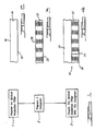
- FIG. 1 is a flow diagram depicting the steps of forming a filter device according to the methods of the present invention;
- FIG. 2 is a cross-section of an optical radiation filter;
- FIG. 3 is a cross-section of a reflection hologram; and
- FIG. 4 is a cross-section of a filter device of the present invention.
- While this invention is described in connection with a filter device suitable for aerospace cockpit applications, it should be recognized by one skilled in the art that a variety of devices, and methods of making the same, for non-aerospace cockpit applications are within the scope of the present invention.
- The
device 10 of the present invention comprisesholographic means 12 disposed in a spaced relationship with optical radiation filter means 14. The optical radiation filter means 14, having a predetermined thickness, are provided for filtering incident radiation of at least a first predetermined range or band of wavelengths. As used herein, the expression "optical radiation filter" refers to a filter or combination of filters capable of filtering radiation of a predetermined range or band of wavelengths, and is not intended to be limited to filtering visible light radiation. The holographic means 12, having a predetermined thickness, are provided for diffracting radiation of at least a second predetermined range or band of wavelengths. Used in combination with each other, the optical radiation filter means and the holographic means transmit predetermined amounts of one or more predetermined wavelengths of radiation. Various results obtained by this unique combination have previously been unattainable using the present holographic means or optical radiation filter means singly. - In a highly preferred embodiment, it is preferred to produce a
filter device 10, suitable for applications such as in aircraft cockpits, which comprises ahologram 12 and anoptical radiation filter 14 disposed in a spaced relationship. The spacing between theoptical radiation filter 14 and thehologram 10 ranges from as little as about zero inches to a distance limited only by operating and/or equipment limitations. Thus, it is contemplated that the optical radiation filter may be in contact with each other, or disposed in a system, such as an optical viewing system, so that they are separated by one or more suitable media, such as air. - The present preferred embodiment is described in connection with a filter device and method of making the same, for use to permit improved viewing of a night imaging systems which are employed in aircraft equipped with head-up display units. Thus, to facilitate optimal night vision and head-up display observation, while minimizing light from undesired sources, the
filter device 10 of the present invention should preferably allow infrared radiation to pass unattenuated; filter substantially all cockpit light; and transmit at least at about 50% attenuation a narrow bandwidth of light of about 543 nm. - Referring to
step 1 of FIG. 1 and FIG. 2, to prepare afilter device 10 according to the methods of the present invention, optical radiation filter means 14 having first andsecond surfaces - The Schott BG-7B, as described for use in the present embodiment, preferably has a thickness of about one-eighth inch. The thickness dimension, however, may be varied to take into account various properties obtainable by varying filter thickness and will depend largely upon the application, and/or operating conditions, of the
ultimate filter device 10. - Optical radiation filter means 14, which are suitable for the use in the present devices also include, without limitation, known band-pass filters, such as narrow and/or broad band-pass filters, and may suitably be absorption and/or interference filters. For instance, without limitation, the filters employed in the methods and devices of the present invention may be selected from those filters listed in Table I. The characteristics of the filters are described according to their approximate x and y coordinate values as they would appear if plotted on a known C.I.E. chromaticity diagram, which diagram is described in detail in B. D. McMains, Recommendations for Color Limitation of Illuminated Devices Used in Connection with AN/AVS-6 Night Vision Goggles, presented October 19, 1983, SAE A-20A subcommittee -- meeting No. 52, which is hereby expressly incorporated by reference. As explained by McMains, C.I.E. chromaticity diagrams display the relative wavelengths and purity of colored light as generated by an equal energy source.

- As can be seen, however, when used singly, the above optical radiation filter means 14 likely fail to filter some wavelengths of radiation, thereby rendering the filter means unsuitable for many applications. For instance, in the context of aircraft cockpit applications where night imaging systems are employed in addition to head-up display units, use of a filter singly such as the use of a Schott BG-7B filter singly, is less preferred because the Schott BG-7B tends to transmit too much undesired light having a wavelength of about 543 nm, thereby tending to overdrive the night imaging system's intensifier.
- Thus, referring to step 2 of FIG. 1, and FIG. 3, holographic means having first and
second surfaces step 3 of FlG. 1 and FlG. 4, the optical radiation filter means 14 are coupled, i.e. combined with, the holographic means 12. The optical radiation filter means 14 can be coupled with the holographic means 12 so that the space maintained between them is as little as about zero inches. The holographic means 12 is provided for diffracting radiation of at least a second predetermined band of range or wavelengths. More particularly, when combined with the optical filter means 14, the holographic means 12 facilitates trimming or narrowing of the bandwidth of a source of incident light, as well as reducing the amount of transmission of such light to a predetermined level. - Preferably, the optical radiation filter means 14 is coupled with the holographic means 12 by adjoining the optical radiation filter means with the holographic means 12 using a suitable adhesive at an
interface 24, defined by the second surface of the optical radiation filter means and the first surface of the holographic means. An example of a suitable optical adhesive is Norland Optical Cement NOA 61, which is an ultraviolet curable polyurethane-containing compound. - Preferably, the
second surface 18 of the optical radiation means is disposed adjacent and conterminous with thefirst surface 20 of the holographic means. It should be recognized, however, that a variety of combinations of optical filters and holograms are obtainable according to the methods and devices of the present invention. Thus, it is within the scope of methods and devices of the present invention to form holographic means 12 directly upon thesecond surface 18 of the optical radiation filter means. Alternatively, it is possible to employ additional layers between said optical radiation means. For instance, it is contemplated that a clear protective layer such as a clear gelatin layer, or other suitable layer, may be employed between the optical radiation means 14 and the holographic means 12. Further, it is within the scope of the present methods and devices that the holographic means 12, and optical radiation filter means 14, which are disposed in a spaced relationship with each other, are separated for a predetermined distance by a suitable medium, such as air. - The preferred holographic means 12 employed in the present invention is a reflection hologram, and more preferably a zero-angle reflection hologram. That is, the preferred holographic means is a hologram having an interference pattern 26 (i.e. fringes) recorded in the hologram substantially parallel to the first and
second surfaces - The
preferred hologram 12 is substantially flat and the first andsecond surfaces - The fringes of the present preferred hologram are spaced at one or more predetermined distances with respect to each other and with respect to the first and
second surfaces - Thus, according to the methods and devices of the present invention, holographic means 12 can be provided to diffract a more narrow bandwidth of radiation than previously obtainable using an optical filter singly. Holographic means of the present preferred embodiment preferably has a thickness of about 0.001 inches.
- It will be appreciated by one skilled in the art that with some modification to the methods and devices of the present invention, the ranges of wavelengths filtered by the devices of the present invention may be selected and varied to suit particular applications where selective transmission of one or more particular wavelengths is desired.
- The
filter device 10 of the present invention thus takes advantage of relatively precise diffraction properties obtainable by using holograms to trim, e.g. "fine tune", an optical radiation filter, such as the Schott BG-7B, when, the hologram and the optical radiation filter are used in combination with each other. - A completed
filter device 10, such as the one described above, which comprises an optical radiation filter in face-to-face combination with a hologram will preferably have a thickness of about one-eight (1/8) inches. One skilled in the art will appreciate, however, that device thickness can be varied by varying the thicknesses of theoptical radiation filter 14 and/or thehologram 12, wherein by varying the thickness it is possible to vary the characteristics of thefilter device 10. Further, the spaced relationship maintained between the hologram and the optical radiation filter may be such that the hologram and optical radiation filter are separated for a predetermined distance by a suitable medium, such as air. This latter embodiment can be accomplished in any suitable manner, including fixably positioning the optical radiation filter at a predetermined distance from the hologram using suitable mechanical means. - The completed
optical filter device 10 can be fitted to a variety of imaging systems, such as an ANVIS system, using suitable fitting means such as a cover glass for the objective lens in that system. -
Filter devices 10 prepared according to the methods of the present invention may be employed in many applications where the transmission of a narrow band of radiation, such as light, of a relatively precise range of wavelengths is desired. For instance, the present filter devices may be employed in applications where transmission of a narrow band of light is desired in order to simulate monochromatic light. - Further, various combinations of filters and holograms may optionally be employed, including, without limitation, filter combinations such as those comprising a narrow band interference filter and a holographic reflection filter; a broad band interference filter and a holographic reflection filter; a broad band absorption interference filter and a holographic reflection filter; or any other combination where it is desired to narrow the transmission range of a filter by a relatively small amount.
- One skilled in the art should realize that the methods and devices of the present invention can be varied to accommodate operating conditions of various applications, and are not limited in scope to aircraft cockpit applications. For instance, without limitation, devices of the present invention may be employed anywhere the filter device is desired to have a sharper cut-off than normal, and where the transmission is narrower than normal.
- The
filter device 10 of the present invention preferably is prepared by providing anoptical radiation filter 14 of a predetermined thickness, having afirst surface 16 and asecond surface 18, capable of filtering optical radiation of at least a first predetermined range of wavelengths; providing ahologram 12 of a predetermined thickness, having afirst surface 20 and asecond surface 22, capable of diffracting radiation of at least a second predetermined range of wavelengths; and coupling thefirst surface 20 of saidhologram 12 with thesecond surface 18 of saidoptical radiation filter 14. - Various optical radiation filters are suitable for employment in the methods and devices of the present invention and include, without limitation, narrow and/or broad band-pass filters; and may suitably be absorption and/or interference filters, or combinations thereof.
- To prepare a
filter device 10 of the present embodiment, such as one for use in aircraft cockpits where night imaging systems are used in addition to head-up display units, preferably, the optical filter provided will have a thickness of about 1/8 inch. The filter should preferably be substantially flat, although it is appreciated that, in many applications, filters having a curvature may suitably be employed. - The hologram is provided preferably by preparing a hologram according to any method capable of yielding preferred diffraction characteristics for the desired application.
- One preferred method of preparing a hologram for emplopment in the devices of the present invention is summarily described as the steps of processing an exposed interference pattern in a photosensitive layer, which layer has been coated on a suitable substrate, to form a hologram. The following is a more detailed description which makes reference, to a large extent, to a number of steps which are known in the art and are summarized in H. M. Smith, Principles of Holography, John Wiley and Sons, Inc., 2d ed. 1975; and H. M. Smith, Holographic Recording Materials, Springer Verlay, 1977, which are hereby expressly incorporated by reference.
- The hologram prepared according to the methods described herein is preferably a reflection-type hologram having substantially zero degree fringes. That is, the interference pattern recorded as the hologram is substantially parallel to the first and
second surfaces hologram 12. - The holograms of the present invention preferably should be prepared to avoid producing noise holograms. Noise holograms, which arise partly due to "air-glass" interface reflection, i.e. the reflection occuring during hologram exposure due partly to the interface between the recording medium and air. Noise holograms are undesirable for at least two reasons. First, reflection-type noise holograms typically generate an undesired reflection color for the hologram. Second, transmission type noise holograms tend to generate an undesirable rainbow-like blurring and distortion of imagery obtained using the hologram.
- Thus, to prepare a hologram that is substantially noise free, a suitable holographic recording medium having a predetermined thickness is provided. Preferably the recording medium is substantially flat. However, the dimensions and shape of the recording medium are limited only by practical considerations, including manufacturing equipment and ultimate use for the completed hologram. Preferably, the recording medium is prepared by coating a photosensitive layer, preferably a sensitized dichromated gelatin layer, onto a major surface of a suitable substrate. Various coating methods may be suitably employed and include cast coating, doctor blade coating, spray coating, dip coating, and resin coating.
- Suitable substrates include a front surfaced mirror in applications where it is preferred that the gelatin layer is ultimately peeled off. Other substrates may be employed and include without limitation, transparent substrates such as thin glass plates which are index matched to a mirror during subsequent holographic exposure steps, photographic grade mylar, polycarbonate, polyester, and cellulose acetate. Further, it is possible to employ the
optical radiation filter 14 as the present substrate. - In a number of applications, a plurality of spacers should preferably be disposed on the major surface of the substrate. The spacers serve to support the preferred gelatin layer during exposure. Suitable spacers include glass beads in a urethane matrix, steel balls or the like.
- Preferably, the spacers that are employed are separated from each other by a distance of about 0.040 inches. The spacers preferably support the layer and are index matched to the layer with a suitable index matching fluid such as mineral oil. Alternative index matching fluids include, without limitation, xylene, and microscope immersion fluid.
- Alternate methods of avoiding production of noise holograms, such as those generated in part by air-glass interface reflection include, in addition to using the above method of index matching, coating the substrate with an antireflective (AR) coating; adding an antireflective coated cover glass which is itself index matched to the substrate; moving an AR-coated cover glass with respect to the substrate during holographic exposure as disclosed in United States Patent No. 4,458,977 which is hereby expressly incorporated by reference; using a suitable complex prism assembly to facilitate prevention of undesirable reflections from reaching the hologram; or using a scanning exposure laser beam with a beam diameter small enough to avoid the possibility that a reflected beam generated by an exposure beam will overlap (and interfere with) the primary beam generated by the exposure beam.
- After preparing the substrate for exposure using known techniques, including a step of drying the recording medium to a predetermined moisture content, a hologram is exposed in the recording medium using conventional methods to form
holographic fringes 26. For instance, a suitable method of exposing holographic fringes is described in L. Solymar, D. J. Cook, Volume Holography and Volume Grating, Academic Press, 1981, which is hereby expressly incorporated by reference. - To summarize a procedure for exposing a hologram, a holographic exposure is preferably made using a substantially collimated laser light beam. The collimated beam comprises a first entering beam. A reflection caused by the first beam off a mirror, or other suitable reflective medium which is preferably associated with the substrate provides a second beam necessary for holographic recording. The beams are provided at one or more predetermined exposure levels. For the present embodiment, the preferred exposure level is about 150 millijoules/cm².
- The beams are introduced into the recording medium at one or more predetermined angles of illumination. The angle of illumination is largely dependent on the particular dichromated gelatin being used and the wavelength of laser light being used. For example, for a standard 300 bloom porkskin gelatin and 514.5nm argon laser, the preferred angle of illumination is about 28 degrees. Optionally, to facilitate holographic exposure it should be appreciated that specialized anti-reflective coatings may be employed, i.e. coatings that exhibit lower reflectivity at a particular angle or wavelength such as standard multilayer interference coatings, ¼ -wavelength magnesium fluoride coatings, or Vee coatings. The holographic fringes that are formed in the recording medium are areas of high and low indices of refraction corresponding in space to the interference pattern formed at the intersection of the two coherent beams supplied by the laser.
- After exposure, the hologram is preferably processed by employment of conventional holographing processing steps. For instance, the steps of processing the preferred dichromated gelatin are known in the art and are described in L. Solymar, D. J. Cook, Volume Holography and Volume Grating; Academic press, 1981, which is hereby expressly incorporated by reference. Briefly, a typical process comprises the steps of removing substantially all remaining index matching fluid from the preferred gelatin by employment of suitable solvents such as freon, hexane, or freon-alcohol mixtures. The gelatin is then swollen by soaking it in a suitable solution, such as one containing about 30 millimolar triethanol amine. This step also serves an additional purpose of removing excess dichromate from the gelatin. The solution is preferably rapidly removed by dehydration steps, such as by soaking the preferred gelatin in consecutive baths having an increasing concentration of from about 75 volume percent to about 100 volume percent of isopropyl alcohol in water.
- After processing, the
hologram 12 is preferably heated at one or more predetermined temperatures for one or more predetermined lengths of time to generate one or more predetermined wavelengths of peak reflectivity in the hologram. Preferably, the hologram is heated at a temperature of about 60°C to about 120°C until the thickness of the gelatin (hence the wavelength of peak reflectivity) is substantially stable. In the present preferred embodiment, this step entails baking the hologram at about 100° for about two weeks to yield a hologram suitable for diffracting a range of wavelengths suitable for applications employing a head-up display unit in connection with a night imaging system such as the ANVIS system; i.e. a hologram exhibiting a peak reflectivity of light having a range of wavelengths of about 550 to about 580 nm, having a bandwidth of about 25nm to about 30nm. - If the wavelength at normal is not within these ranges, suitable remedial measures can be taken to obtain such wavelength and include adjusting the angle of hologram exposure.
- After obtaining the predetermined wavelength within the hologram, the
hologram 12 is optionally sealed with a suitable sealing layer to protect it from contamination such as moisture. Preferably, this can be done by attaching one or more of the hologram's surfaces to a clear cover glass. Preferably, the clear cover glass is attached to the surfaces of the hologram using suitable optical adhesives such as Norland Optical Cement NOA 61. - The
first surface 20 of thehologram 12 can then be attached to thesecond surface 18 of theoptical radiation filter 14. Preferably, thefirst surface 20 of thehologram 12 is attached to thesecond surface 18 of the optical radiation filter using a suitable optical adhesive, such as Norland Optical Cement NOA 61. - It should be appreciated that if the optional clear cover glass is omitted, the
first surface 20 of thehologram 12 could be attached directly to thesecond surface 18 of theoptical radiation filter 14. For instance, thefirst surface 20 of thehologram 12 could be attached directly to thesecond surface 18 of theoptical radiation filter 14 using a suitable adhesive, such as Norland Optical Cement NOA 61, to form anoptical filter device 10. - It is also contemplated that a hologram may be prepared utilizing a preferred optical radiation filter, such as those described above, as the hologram's substrate, thereby avoiding any need to adhere the filter to the hologram using adhesive. Further, if the hologram and optical radiation filter are separated for a predetermined distance by a suitable medium such as air, the hologram and optical radiation filter may be coupled in any suitable manner. For instance, suitable mechanical means may be employed to fixably position the optical radiation filter at a predetermined distance from the hologram.
- Devices prepared according to the present process should exhibit approximately 30% peak transmission at about 543nm with a bandwidth of about 15nm thereby rendering them suitable for use with night imaging systems in aircraft cockpits having head-up display units therein.
- It should be understood that while this invention has been described in connection with one presently preferred example, that other modifications will be apparent to those skilled in the art after a study of the specification, drawings, and following claims.
Claims (20)
Applications Claiming Priority (2)
| Application Number | Priority Date | Filing Date | Title |
|---|---|---|---|
| US07/285,135 US5082337A (en) | 1988-12-16 | 1988-12-16 | Filter device employing a holographic element |
| US285135 | 1999-04-02 |
Publications (2)
| Publication Number | Publication Date |
|---|---|
| EP0373820A2 true EP0373820A2 (en) | 1990-06-20 |
| EP0373820A3 EP0373820A3 (en) | 1991-12-18 |
Family
ID=23092886
Family Applications (1)
| Application Number | Title | Priority Date | Filing Date |
|---|---|---|---|
| EP19890312696 Withdrawn EP0373820A3 (en) | 1988-12-16 | 1989-12-06 | Filter device employing a holographic element |
Country Status (5)
| Country | Link |
|---|---|
| US (1) | US5082337A (en) |
| EP (1) | EP0373820A3 (en) |
| JP (1) | JPH06103361B2 (en) |
| CA (1) | CA2002988C (en) |
| IL (1) | IL92881A (en) |
Cited By (4)
| Publication number | Priority date | Publication date | Assignee | Title |
|---|---|---|---|---|
| EP0557162A1 (en) * | 1992-02-18 | 1993-08-25 | Sextant Avionique | Holographic radiation protection filter, particularly for lasers |
| ES2051224A2 (en) * | 1992-06-25 | 1994-06-01 | Univ Madrid | Narrow-band interference filter with photorefractive material |
| US7040664B2 (en) | 1996-10-10 | 2006-05-09 | Securency Pty Ltd | Self-verifying security documents |
| US7488002B2 (en) | 1998-07-02 | 2009-02-10 | Securency Pty Limited | Security and/or value document |
Families Citing this family (19)
| Publication number | Priority date | Publication date | Assignee | Title |
|---|---|---|---|---|
| US5491570A (en) * | 1991-07-26 | 1996-02-13 | Accuwave Corporation | Methods and devices for using photorefractive materials at infrared wavelengths |
| CA2114226A1 (en) * | 1991-07-26 | 1993-02-18 | George Anthony Rakuljic | Photorefractive systems and methods |
| US5440669A (en) * | 1991-07-26 | 1995-08-08 | Accuwave Corporation | Photorefractive systems and methods |
| US5691989A (en) * | 1991-07-26 | 1997-11-25 | Accuwave Corporation | Wavelength stabilized laser sources using feedback from volume holograms |
| US5335098A (en) * | 1991-07-26 | 1994-08-02 | Accuwave Corporation | Fixing method for narrow bandwidth volume holograms in photorefractive materials |
| US5796096A (en) * | 1991-07-26 | 1998-08-18 | Accuwave Corporation | Fabrication and applications of long-lifetime, holographic gratings in photorefractive materials |
| FR2712990B1 (en) * | 1993-11-22 | 1996-04-05 | Commissariat Energie Atomique | Broadband mirror with high reflectivity and method for producing such a mirror. |
| US5502455A (en) * | 1994-07-21 | 1996-03-26 | Honeywell Inc. | Method and appartus for producing a symbology display into a night vision system |
| US6139147A (en) * | 1998-11-20 | 2000-10-31 | Novartis Ag | Actively controllable multifocal lens |
| US6139146A (en) * | 1997-12-29 | 2000-10-31 | Novartis Ag | Programmable corrective lenses |
| US5997140A (en) * | 1997-12-29 | 1999-12-07 | Novartis Ag | Actively controllable multifocal lens |
| US6429429B1 (en) * | 2000-06-22 | 2002-08-06 | Ford Global Technologies, Inc. | Night vision system utilizing a diode laser illumination module and a method related thereto |
| US20020093701A1 (en) * | 2000-12-29 | 2002-07-18 | Xiaoxiao Zhang | Holographic multifocal lens |
| WO2008017063A2 (en) | 2006-08-03 | 2008-02-07 | Inphase Technologies, Inc. | Miniature single actuator scanner for angle multiplexing with circularizing and pitch correction capability |
| JP2010503025A (en) | 2006-08-28 | 2010-01-28 | インフェイズ テクノロジーズ インコーポレイテッド | Provided a new type of Fourier transform (FT) lens (204) that improves phase conjugation in holographic data systems. This type of FT lens has a uniquely large isoplanatic patch, which is of assembly tolerance Allows relaxation, asymmetric read / write architecture, and compensation for tilted plate aberrations in the media |
| JP2010505214A (en) | 2006-09-29 | 2010-02-18 | インフェイズ テクノロジーズ インコーポレイテッド | Magnetic field position feedback for holographic storage scanners |
| WO2008121158A1 (en) * | 2007-04-02 | 2008-10-09 | Inphase Technologies, Inc. | Non-ft plane angular filters |
| US8141782B2 (en) * | 2007-07-10 | 2012-03-27 | Inphase Technologies, Inc. | Dual-use media card connector for backwards compatible holographic media card |
| CA2692870A1 (en) | 2007-07-10 | 2009-01-15 | Inphase Technologies, Inc. | Enabling holographic media backwards compatibility with dual-use media card connector |
Citations (4)
| Publication number | Priority date | Publication date | Assignee | Title |
|---|---|---|---|---|
| GB1574351A (en) * | 1978-02-27 | 1980-09-03 | Smiths Industries Ltd | Display apparatus |
| GB2054195A (en) * | 1979-07-11 | 1981-02-11 | Aga Ab | Colour Selective Directional Mirrors |
| US4412719A (en) * | 1981-04-10 | 1983-11-01 | Environmental Research Institute Of Michigan | Method and article having predetermined net reflectance characteristics |
| EP0419199A2 (en) * | 1989-09-19 | 1991-03-27 | Fujitsu Limited | Heads-up display |
Family Cites Families (11)
| Publication number | Priority date | Publication date | Assignee | Title |
|---|---|---|---|---|
| US3695744A (en) * | 1971-01-14 | 1972-10-03 | Rca Corp | Holographic multicolor technique |
| US3944322A (en) * | 1975-01-16 | 1976-03-16 | Polaroid Corporation | Light filtering arrangement for holographic displays |
| US4458977A (en) * | 1981-06-01 | 1984-07-10 | Hughes Aircraft Company | Systems for forming improved reflection holograms with a single beam |
| US4863224A (en) * | 1981-10-06 | 1989-09-05 | Afian Viktor V | Solar concentrator and manufacturing method therefor |
| US4637678A (en) * | 1982-06-01 | 1987-01-20 | Hughes Aircraft Company | Holographic laser protection device |
| US4601533A (en) * | 1982-10-29 | 1986-07-22 | The United States Of America As Represented By The Secretary Of The Navy | Laser eye protection visor using multiple holograms |
| US4786125A (en) * | 1983-08-22 | 1988-11-22 | Farrand Optical Co. | Ocular protective apparatus |
| US4802719A (en) * | 1983-08-22 | 1989-02-07 | Farrand Optical Co. | Infra-red laser shield |
| JPS62903A (en) * | 1985-06-05 | 1987-01-06 | Sumitomo Chem Co Ltd | Near infrared ray absorbing filter |
| US4779942A (en) * | 1985-12-09 | 1988-10-25 | United Technologies Corporation | NVG compatible red light |
| US4830441A (en) * | 1987-03-25 | 1989-05-16 | Kaiser Optical Systems | Holographic filter construction for protective eyewear |
-
1988
- 1988-12-16 US US07/285,135 patent/US5082337A/en not_active Expired - Lifetime
-
1989
- 1989-11-15 CA CA002002988A patent/CA2002988C/en not_active Expired - Fee Related
- 1989-12-06 EP EP19890312696 patent/EP0373820A3/en not_active Withdrawn
- 1989-12-15 JP JP1325739A patent/JPH06103361B2/en not_active Expired - Lifetime
- 1989-12-25 IL IL9288189A patent/IL92881A/en not_active IP Right Cessation
Patent Citations (4)
| Publication number | Priority date | Publication date | Assignee | Title |
|---|---|---|---|---|
| GB1574351A (en) * | 1978-02-27 | 1980-09-03 | Smiths Industries Ltd | Display apparatus |
| GB2054195A (en) * | 1979-07-11 | 1981-02-11 | Aga Ab | Colour Selective Directional Mirrors |
| US4412719A (en) * | 1981-04-10 | 1983-11-01 | Environmental Research Institute Of Michigan | Method and article having predetermined net reflectance characteristics |
| EP0419199A2 (en) * | 1989-09-19 | 1991-03-27 | Fujitsu Limited | Heads-up display |
Cited By (4)
| Publication number | Priority date | Publication date | Assignee | Title |
|---|---|---|---|---|
| EP0557162A1 (en) * | 1992-02-18 | 1993-08-25 | Sextant Avionique | Holographic radiation protection filter, particularly for lasers |
| ES2051224A2 (en) * | 1992-06-25 | 1994-06-01 | Univ Madrid | Narrow-band interference filter with photorefractive material |
| US7040664B2 (en) | 1996-10-10 | 2006-05-09 | Securency Pty Ltd | Self-verifying security documents |
| US7488002B2 (en) | 1998-07-02 | 2009-02-10 | Securency Pty Limited | Security and/or value document |
Also Published As
| Publication number | Publication date |
|---|---|
| EP0373820A3 (en) | 1991-12-18 |
| CA2002988A1 (en) | 1990-06-16 |
| IL92881A (en) | 1994-12-29 |
| US5082337A (en) | 1992-01-21 |
| JPH02275902A (en) | 1990-11-09 |
| JPH06103361B2 (en) | 1994-12-14 |
| CA2002988C (en) | 1995-05-09 |
| IL92881A0 (en) | 1990-09-17 |
Similar Documents
| Publication | Publication Date | Title |
|---|---|---|
| US5082337A (en) | Filter device employing a holographic element | |
| US4582389A (en) | Holographic device | |
| US5103323A (en) | Multi-layer holographic notch filter | |
| US6922267B2 (en) | Image display apparatus | |
| US5432623A (en) | Optical lens incorporating an integral hologram | |
| US5724189A (en) | Methods and apparatus for creating an aspheric optical element and the aspheric optical elements formed thereby | |
| US4960311A (en) | Holographic exposure system for computer generated holograms | |
| DE69333759T2 (en) | IMAGE DISPLAY UNIT | |
| EP0046218B1 (en) | Method and apparatus for production of holographic optical elements | |
| EP0151455B1 (en) | Head up display system | |
| JPH0343779A (en) | Dispersion compensation windshield hologram virtual-image display unit | |
| JPH04500869A (en) | heads up display | |
| JPS6135416A (en) | Holographic display system | |
| JPS62502150A (en) | Graded index aspherical combiner and display system using it | |
| GB2054195A (en) | Colour Selective Directional Mirrors | |
| EP0296710A2 (en) | Head-up display combiner utilizing a cholesteric liquid crystal element | |
| US4582394A (en) | Display apparatus | |
| EP0811859B1 (en) | Holographic reflector and reflective liquid crystal display using it | |
| GB1574351A (en) | Display apparatus | |
| EP0558700B1 (en) | Non-interfering color viewing system using spectral multiplexing | |
| JP3204966B2 (en) | Manufacturing method of thin film optical element | |
| US4178181A (en) | Interference film photography | |
| EP3667396A1 (en) | Display device | |
| Ramsbottom et al. | Holography for automotive head-up displays | |
| JPH04233572A (en) | Holographic display device |
Legal Events
| Date | Code | Title | Description |
|---|---|---|---|
| PUAI | Public reference made under article 153(3) epc to a published international application that has entered the european phase |
Free format text: ORIGINAL CODE: 0009012 |
|
| AK | Designated contracting states |
Kind code of ref document: A2 Designated state(s): DE ES FR GB IT NL SE |
|
| PUAL | Search report despatched |
Free format text: ORIGINAL CODE: 0009013 |
|
| AK | Designated contracting states |
Kind code of ref document: A3 Designated state(s): DE ES FR GB IT NL SE |
|
| 17P | Request for examination filed |
Effective date: 19920522 |
|
| 17Q | First examination report despatched |
Effective date: 19940121 |
|
| STAA | Information on the status of an ep patent application or granted ep patent |
Free format text: STATUS: THE APPLICATION IS DEEMED TO BE WITHDRAWN |
|
| 18D | Application deemed to be withdrawn |
Effective date: 19950419 |