EP0374902A2 - Microphone system for determining the direction and position of a sound source - Google Patents
Microphone system for determining the direction and position of a sound source Download PDFInfo
- Publication number
- EP0374902A2 EP0374902A2 EP89123591A EP89123591A EP0374902A2 EP 0374902 A2 EP0374902 A2 EP 0374902A2 EP 89123591 A EP89123591 A EP 89123591A EP 89123591 A EP89123591 A EP 89123591A EP 0374902 A2 EP0374902 A2 EP 0374902A2
- Authority
- EP
- European Patent Office
- Prior art keywords
- microphone
- sound
- microphone body
- microphones
- sound source
- Prior art date
- Legal status (The legal status is an assumption and is not a legal conclusion. Google has not performed a legal analysis and makes no representation as to the accuracy of the status listed.)
- Granted
Links
Images


Classifications
-
- H—ELECTRICITY
- H04—ELECTRIC COMMUNICATION TECHNIQUE
- H04R—LOUDSPEAKERS, MICROPHONES, GRAMOPHONE PICK-UPS OR LIKE ACOUSTIC ELECTROMECHANICAL TRANSDUCERS; DEAF-AID SETS; PUBLIC ADDRESS SYSTEMS
- H04R1/00—Details of transducers, loudspeakers or microphones
- H04R1/20—Arrangements for obtaining desired frequency or directional characteristics
- H04R1/32—Arrangements for obtaining desired frequency or directional characteristics for obtaining desired directional characteristic only
- H04R1/34—Arrangements for obtaining desired frequency or directional characteristics for obtaining desired directional characteristic only by using a single transducer with sound reflecting, diffracting, directing or guiding means
- H04R1/38—Arrangements for obtaining desired frequency or directional characteristics for obtaining desired directional characteristic only by using a single transducer with sound reflecting, diffracting, directing or guiding means in which sound waves act upon both sides of a diaphragm and incorporating acoustic phase-shifting means, e.g. pressure-gradient microphone
-
- G—PHYSICS
- G01—MEASURING; TESTING
- G01S—RADIO DIRECTION-FINDING; RADIO NAVIGATION; DETERMINING DISTANCE OR VELOCITY BY USE OF RADIO WAVES; LOCATING OR PRESENCE-DETECTING BY USE OF THE REFLECTION OR RERADIATION OF RADIO WAVES; ANALOGOUS ARRANGEMENTS USING OTHER WAVES
- G01S3/00—Direction-finders for determining the direction from which infrasonic, sonic, ultrasonic, or electromagnetic waves, or particle emission, not having a directional significance, are being received
- G01S3/80—Direction-finders for determining the direction from which infrasonic, sonic, ultrasonic, or electromagnetic waves, or particle emission, not having a directional significance, are being received using ultrasonic, sonic or infrasonic waves
- G01S3/801—Details
-
- G—PHYSICS
- G01—MEASURING; TESTING
- G01V—GEOPHYSICS; GRAVITATIONAL MEASUREMENTS; DETECTING MASSES OR OBJECTS; TAGS
- G01V1/00—Seismology; Seismic or acoustic prospecting or detecting
- G01V1/001—Acoustic presence detection
-
- H—ELECTRICITY
- H04—ELECTRIC COMMUNICATION TECHNIQUE
- H04R—LOUDSPEAKERS, MICROPHONES, GRAMOPHONE PICK-UPS OR LIKE ACOUSTIC ELECTROMECHANICAL TRANSDUCERS; DEAF-AID SETS; PUBLIC ADDRESS SYSTEMS
- H04R1/00—Details of transducers, loudspeakers or microphones
- H04R1/08—Mouthpieces; Microphones; Attachments therefor
- H04R1/083—Special constructions of mouthpieces
-
- H—ELECTRICITY
- H04—ELECTRIC COMMUNICATION TECHNIQUE
- H04R—LOUDSPEAKERS, MICROPHONES, GRAMOPHONE PICK-UPS OR LIKE ACOUSTIC ELECTROMECHANICAL TRANSDUCERS; DEAF-AID SETS; PUBLIC ADDRESS SYSTEMS
- H04R1/00—Details of transducers, loudspeakers or microphones
- H04R1/20—Arrangements for obtaining desired frequency or directional characteristics
- H04R1/32—Arrangements for obtaining desired frequency or directional characteristics for obtaining desired directional characteristic only
- H04R1/40—Arrangements for obtaining desired frequency or directional characteristics for obtaining desired directional characteristic only by combining a number of identical transducers
- H04R1/406—Arrangements for obtaining desired frequency or directional characteristics for obtaining desired directional characteristic only by combining a number of identical transducers microphones
Definitions
- the invention relates to a microphone system for determining the direction and position of a sound source.
- the predominantly used microphones register the sound pressure of a sound signal emanating from a sound source. Since the sound pressure is a scalar quantity, the directional information of the sound signal, which is a statement about the position of the signal source, is lost in these “pressure” microphones.
- Double microphones are used with which the sound pressure and the temporal pressure gradient as well as the sound speed are recorded. Extreme demands on the equality of the microphones have to be met. To measure the directional distribution of a sound field emanating from a sound source, it is necessary to scan the entire solid angle with the microphone axis.
- the invention has for its object to provide a microphone system that is suitable for the sound pressure gradient and the sound velocity Measure the amount, phase and direction so that the position of sound sources can be determined and vector intensity measurements are possible.
- This microphone system is said to be suitable for the measurement of sound waves in gaseous, liquid and solid media and can also be used as a hydrophone or geophone, for example.
- a single microphone with a microphone body preferably a ball
- the microphone body being exposed to the sound field to be measured and the oscillating movement of the microphone body induced by the sound field with vibration sensors built into it, e.g. . Accelerometers is measured.
- the vibration acceleration is a measure of the sound pressure gradient and can be calibrated to this and also to the local sound velocity.
- the direction of a sound source at least three vibration sensors sensitive to the three spatial directions are necessary.
- one or more conventional sound pressure microphones are additionally arranged in the surface of the microphone body.
- the registration of the sound pressure and the speed of sound makes it possible to determine the vectorial sound intensity.
- the microphone according to the invention can also be designed to be frequency-selective. There is a natural sensitivity maximum at the frequency whose half wavelength corresponds to the diameter of the microphone body. In this case there are opposing pressure conditions on the front and the back of the microphone body. An additional increase in resonance occurs when the microphone body is connected via spring coupling to a counterweight, which is preferably suspended elastically within the microphone body. Such an arrangement represents a single-track oscillator with an adjustable resonance frequency and self-damping. approximate the subjective amplitude rating.
- a cylindrical microphone body instead of a ball may be sufficient.
- the vibration sensors are distributed over the circumference of the cylinder.
- the direction finding base is determined by the spatial distance of the vibration sensors.
- this DF base it is possible to arrange a plurality of such microphones in a spatial pattern, a so-called array, wherein the individual microphone bodies can be the same or different in size at the same time.
- this increases the DF base and thus the DF accuracy, and on the other hand - by staggering the microphone body sizes - increases the frequency selectivity.
- FIGS. 1 to 6 each schematically show an exemplary embodiment of a microphone or a microphone arrangement according to the invention.
- FIG. 1 shows the basic design of a microphone according to the invention, with which both the sound pressure and the sound speed can be measured, so that this microphone can be referred to as a gradient microphone.
- This microphone is marked with 1a. It has a microphone body 2, in this case a ball, which is mounted on a microphone stand 4 via an elastic holder 3, for example one or more springs. A plurality of vibration sensors 5 are arranged on the surface of the ball 2, for example acceleration sensors, displacement and / or speed sensors, etc. sensitive in the three spatial directions.
- the ball shape of the microphone body 2 is exemplary here; microphone bodies in the form of a polyhedron can also be used.
- the dimensions of the microphone body 2 should be comparable to the wavelength of the highest frequency still to be registered of a sound source to be recorded.
- the internal natural frequencies of the microphone body 2 should lie above the frequency range to be measured.
- the microphone body 2 If the microphone body 2 is exposed to a sound field, it experiences a mechanical oscillating movement on its surface due to the different sound pressures, which is measured with the aid of the spatially oriented vibration sensors 5 which are firmly connected to the microphone body 2. In this way, the vectorial sound originating from a sound source can be determined in a pressure gradient. If several sound sources are to be determined simultaneously with respect to direction and position with this gradient microphone 1a, at least one group of three non-collinear vibration sensors must be provided for each sound source.
- a gradient microphone 1b is shown in FIG. 2 in the same schematic representation as in FIG. 1a.
- This gradient microphone 1b differs from that only in that one or more conventional microphones 6, which respond to the sound pressure, are arranged in the surface of the spherical microphone body 2. Together with the gradient and fast signal supplied by the gradient microphone 1a according to FIG. 1, the vectorial sound intensity can then be calibrated and determined using the microphone according to FIG. 2.
- FIG. 3 schematically shows a gradient microphone 1c, which is constructed like the gradient microphone 1a in FIG. 1.
- the spherical microphone body 2 is enclosed in a contact-free manner by a sound-permeable wind screen 7, which in turn is connected to the microphone stand 4.
- the wind screen 7 is e.g. from a single or multi-layer foam, sieve or foil jacket.
- the gradient microphone 1d shown schematically in Fig. 4 has a microphone body 2, which is composed of an outer microphone body 2 'and a counter mass 2 ⁇ arranged within this microphone body.
- the two masses 2 'and 2 ⁇ are connected to each other via several springs 8.
- vibration sensors 5 and Sound pressure microphones 6 integrated in the outer microphone body 2 ', as in the microphones described above, vibration sensors 5 and Sound pressure microphones 6 integrated.
- the outer microphone body 2 ' is in turn connected to the microphone stand 4 via elastic holders 3.
- This system represents a resonance system which has the same resonance frequency in all three spatial directions by appropriate adjustment of the spring constants of the elastic supports.
- Such a system is preferably excited by an external sound field at its resonance frequency. In this way, a desired frequency response, for example the evaluation of the frequency approximated to the human ear, can be set.
- additional vibration sensors 9 which are integrated in the counter mass 2 ⁇ , spectral suppression can be achieved by means of anti-resonance phenomena.
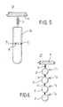
- a simplified form of a gradient microphone 1e shown in FIG. 5 can be used.
- the microphone body consists of a cylinder piece 1e, which in turn is connected to the microphone housing 4 via an elastic holder 3.
- Vibration pickups 5 and possibly sound pressure microphones 6 are provided on the circumference of the cylinder piece 2e.
- a gradient microphone arrangement 1f of several gradient microphones 11, 12, 13 and 14 is shown, which are arranged along a line.
- Each gradient microphone has a microphone body 2, which is equipped with vibration sensors and possibly sound pressure microphones in accordance with the above explanations.
- the individual microphone bodies 2 are each connected to a microphone stand 4 via elastic mounts 3, wherein a separate housing can be provided for each gradient microphone.
- the microphone bodies of the individual gradient microphones are in each case one below the other and only the two outer microphone bodies by elastic holders 3 a common microphone stand 4 are connected.
- This arrangement in an array increases the directional base of the microphone arrangement 1f. A different frequency range can additionally be encompassed by different diameters of the microphone bodies 2.
Abstract
Description
Die Erfindung bezieht sich auf ein Mikrofonsystem zum Bestimmen der Richtung und der Position einer Schallquelle.The invention relates to a microphone system for determining the direction and position of a sound source.
Die überwiegend verwendeten Mikrofone registrieren den Schalldruck eines von einer Schallquelle ausgehenden Schallsignales. Da der Schalldruck eine skalare Größe ist, geht bei diesen "Druck"-Mikrofonen die Richtungsinformation des Schallsignales verloren, die eine Aussage über die Position der Signalquelle ist.The predominantly used microphones register the sound pressure of a sound signal emanating from a sound source. Since the sound pressure is a scalar quantity, the directional information of the sound signal, which is a statement about the position of the signal source, is lost in these “pressure” microphones.
Auf der anderen Seite gibt es sog. Schnellemikrofone, die Informationen hinsichtlich der Geschwindigkeitsamplitude der Energiedichteverteilung bzw. Intensität messen, z.B. in der Ausführung als Bändchen-Mikrofon. Auch dieser Mikrofontyp kann von seiner Bauweise her die Richtungsinformation, die im Schnellevektor enthalten ist, nicht aufnehmen.On the other hand, there are so-called high-speed microphones that measure information regarding the speed amplitude of the energy density distribution or intensity, e.g. in the form of a ribbon microphone. This type of microphone also cannot accommodate the directional information contained in the fast vector due to its construction.
Speziell für Intensitätsmessungen und Richtungsmessungen werden Anordnungen aus mehreren Mikrofonen, z.B. Doppelmikrofone verwendet, mit denen der Schalldruck und der zeitliche Druckgradient sowie die Schallschnelle erfaßt werden. Hierbei sind extreme Anforderungen an die Gleichheit der Mikrofone zu erfüllen. Zur Vermessung der Richtungsverteilung eines von einer Schallquelle ausgehenden Schallfeldes ist es dabei erforderlich, mit der Mikrofonachse den gesamten Raumwinkel abzutasten.Arrangements consisting of several microphones, e.g. Double microphones are used with which the sound pressure and the temporal pressure gradient as well as the sound speed are recorded. Extreme demands on the equality of the microphones have to be met. To measure the directional distribution of a sound field emanating from a sound source, it is necessary to scan the entire solid angle with the microphone axis.
Der Erfindung liegt die Aufgabe zugrunde, ein Mikrofonsystem anzugeben, das geeignet ist, den Schalldruckgradienten und die Schallschnelle nach Betrag, Phase und Richtung zu vermessen, so daß die Position von Schallquellen ermittelt werden kann und vektorielle Intensitätsmessungen möglich sind. Dieses Mikrofonsystem soll für die Messung von Schallwellen in gasförmigen, flüssigen und festen Medien geeignet sein und z.B. auch als Hydrofon oder Geofon verwendet werden können.The invention has for its object to provide a microphone system that is suitable for the sound pressure gradient and the sound velocity Measure the amount, phase and direction so that the position of sound sources can be determined and vector intensity measurements are possible. This microphone system is said to be suitable for the measurement of sound waves in gaseous, liquid and solid media and can also be used as a hydrophone or geophone, for example.
Diese Aufgabe ist gemäß der Erfindung durch die kennzeichnenden Merkmale des Patentanspruches 1 gelöst.This object is achieved according to the invention by the characterizing features of claim 1.
Demgemäß ist lediglich ein einziges Mikrofon mit einem Mikrofonkörper, vorzugsweise einer Kugel, zur Bestimmung der Position und Richtung einer Schallquelle notwendig, wobei der Mikrofonkörper dem zu vermessenden Schallfeld exponiert und die durch das Schallfeld induzierte Schwingbewegung des Mikrofonkörpers mit in diesem eingebauten Schwingungaufnehmern, z .B. Beschleunigungaufnehmern, vermessen wird. Ist der Durchmesser des Mikrofonkörpers, z.B. einer Kugel, klein gegen die Schallwellenlänge, so ist die Schwingungsbeschleunigung ein Maß für den Schalldruckgradienten und kann auf diesen und auch auf die lokale Schallschnelle geeicht werden. Um die Richtung einer Schallquelle zu bestimmen, sind zumindest drei auf die drei Raumrichtungen empfindliche Schwingungsaufnehmer notwendig. Um gleichzeitig n verschiedene Schallquellen zu separieren, sind m nicht-kollinear angebrachte Schwingungsaufnehmer notwendig, wobei m größer als n ist. Der Signalverlauf qn(t) der n.ten Schallquelle errechnet sich aus den Signalen Sm(t) der Aufnehmer nach der Matrizengleichung ![]()
![]()
![]()
![]()
Die Koeffizientenmatrix dieser Gleichung hat dann die Glieder Amn = ![]()
![]()
wobei ![]()
![]()
![]()
![]()
in which ![]()
![]()
Gemäß einer bevorzugten Ausführungsform der Erfindung werden in der Oberfläche des Mikrofonkörpers ein oder mehrere herkömmliche Schalldruckmikrofone zusätzlich angeordnet. Durch die hiermit mögliche Registrierung des Schalldruckes und der Schallschnelle ist auch die Bestimmung der vektoriellen Schallintensität möglich.According to a preferred embodiment of the invention, one or more conventional sound pressure microphones are additionally arranged in the surface of the microphone body. The registration of the sound pressure and the speed of sound makes it possible to determine the vectorial sound intensity.
Das Mikrofon gemäß der Erfindung kann zudem frequenzselektiv ausgelegt werden. Ein natürliches Empfindlichkeitsmaximum besteht bei der Frequenz, deren halbe Wellenlänge dem Durchmesser des Mikrofonkörpers entspricht. In diesem Falle liegen auf der Vorder- und der Rückseite des Mikrofonkörpers gegensinnige Druckverhältnisse vor. Eine zusätzliche Resonanzüberhöhung ergibt sich dann, wenn der Mikrofonkörper über eine Federkopplung mit einer Gegenmasse verbunden ist, die bevorzugt innerhalb des Mikrofonkörpers elastisch aufgehängt ist. Eine solche Anordnung stellt einen einläufigen Schwinger mit einstellbarer Resonanzfrequenz und Eigendämpfung dar. Mit einem solchen System läßt sich z.B. die subjektive Amplitudenbewertung approximieren.The microphone according to the invention can also be designed to be frequency-selective. There is a natural sensitivity maximum at the frequency whose half wavelength corresponds to the diameter of the microphone body. In this case there are opposing pressure conditions on the front and the back of the microphone body. An additional increase in resonance occurs when the microphone body is connected via spring coupling to a counterweight, which is preferably suspended elastically within the microphone body. Such an arrangement represents a single-track oscillator with an adjustable resonance frequency and self-damping. approximate the subjective amplitude rating.
Wenn die Detektierung und Verfolgung von Schallquellen lediglich in einer Ebene verlangt wird, so z.B. das Erfassen und Verfolgen bodengebundener Fahrzeuge, kann anstelle einer Kugel ein zylinderförmiger Mikrofonkörper ausreichend sein. Die Schwingungsaufnehmer sind in diesem Falle über den Zylinderumfang verteilt. Zur Erhöhung der Empfindlichkeit und zur Verringerung des Windgeräusches bei Außenmessungen ist es zweckmäßig, mit einem langgestreckten Mikrofonzylinder eine große Fläche für die Schallbeaufschlagung bereitzustellen.If the detection and tracking of sound sources is only required on one level, such as the detection and tracking of ground-based vehicles, a cylindrical microphone body instead of a ball may be sufficient. In this case, the vibration sensors are distributed over the circumference of the cylinder. In order to increase the sensitivity and to reduce the wind noise during external measurements, it is expedient to provide a large area for the sound exposure with an elongated microphone cylinder.
Bei Außenmessungen ist es zudem vorteilhaft, die Außenfläche des Mikrofones mit Schaumstoff auszuschlagen, Gitterumschließungen und/oder Folienumschließungen zu versehen, um auf diese Weise die bei Mikrofonaufnahmen bekannten Windgeräusche zu minimieren.For external measurements, it is also advantageous to knock out the outer surface of the microphone with foam, to provide grille enclosures and / or foil enclosures, in order in this way to minimize the wind noise known from microphone recordings.
Bei einem Mikrofon gemäß der Erfindung wird zur Richtungsdetektion die Peilbasis durch die räumliche Distanz der Schwingungsaufnehmer bestimmt. Um diese Peilbasis zu vergrößern, ist es möglich, mehrere derartiger Mikrofone in einem räumlichen Muster, einem sog. Array anzuordnen, wobei gleichzeitig die einzelnen Mikrofonkörper in ihrer Größe gleich oder unterschiedlich sein können. Hierdurch wird zum einen die Peilbasis und damit die Peilgenauigkeit vergrößert, zum anderen - durch die Staffelung der Mikrofonkörpergrößen - die Frequenzselektivität gesteigert.In the case of a microphone according to the invention, the direction finding base is determined by the spatial distance of the vibration sensors. In order to enlarge this DF base, it is possible to arrange a plurality of such microphones in a spatial pattern, a so-called array, wherein the individual microphone bodies can be the same or different in size at the same time. On the one hand, this increases the DF base and thus the DF accuracy, and on the other hand - by staggering the microphone body sizes - increases the frequency selectivity.
Die Erfindung ist anhand der Figuren 1 bis 6 näher erläutert, die jeweils schematisch ein Ausführungsbeispiel eines Mikrofons bzw. einer Mikrofonanordnung gemäß der Erfindung zeigen.The invention is explained in more detail with reference to FIGS. 1 to 6, which each schematically show an exemplary embodiment of a microphone or a microphone arrangement according to the invention.
In Fig. 1 ist die Grundausführung eines Mikrofons gemäß der Erfindung dargestellt, mit dem sowohl der Schalldruck als auch die Schallschnelle gemessen werden können, so daß dieses Mikrofon als Gradientenmikrofon bezeichnet werden kann. Dieses Mikrofon ist mit 1a gekennzeichnet. Es weist einen Mikrofonkörper 2, in diesem Falle eine Kugel auf, die über eine elastische Halterung 3, z.B. eine oder mehrere Federn, auf einem Mikrofonstativ 4 gelagert ist. Auf der Oberfläche der Kugel 2 sind mehrere Schwingungsaufnehmer 5 angeordnet, z.B. in den drei Raumrichtungen empfindliche Beschleunigungsaufnehmer, Weg- und/oder Geschwindigkeitsmesser etc.. Die Kugelgestalt des Mikrofonkörpers 2 ist hierbei beispielhaft; ebenso können Mikrofonkörper in Form eines Polyeders verwendet werden. Die Abmessungen des Mikrofonkörpers 2 sollten vergleichbar der Wellenlänge der höchsten noch zu registrierenden Frequenz einer zu erfassenden Schallquelle sein. Die internen Eigenfrequenzen des Mikrofonkörpers 2 sollen oberhalb des zu messenden Frequenzbereiches liegen.1 shows the basic design of a microphone according to the invention, with which both the sound pressure and the sound speed can be measured, so that this microphone can be referred to as a gradient microphone. This microphone is marked with 1a. It has a
Wird der Mikrofonkörper 2 einem Schallfeld ausgesetzt, so erfährt er aufgrund der unterschiedlichen Schalldrücke an seiner Oberfläche eine mechanische Schwingbewegung, die mit Hilfe der räumlich orientierten und fest mit dem Mikrofonkörper 2 verbundenen Schwingungsaufnehmer 5 gemessen wird. Auf diese Weise läßt sich der von einer Schallquelle herrührende, vektorielle Schall druckgradient ermitteln. Sollen mit diesem Gradientenmikrofon 1a mehrere Schallquellen gleichzeitig hinsichtlich Richtung und Position separierbar ermittelt werden, so muß für jede Schallquelle zumindest eine Gruppe aus drei nichtkollinearen Schwingungsaufnehmern vorgesehen werden.If the
In Fig. 2 ist ein Gradientenmikrofon 1b in der gleichen schematischen Darstellung wie in Fig. 1a gezeigt. Von jenem unterscheidet sich dieses Gradientenmikrofon 1b lediglich dadurch, daß in der Oberfläche des kugeligen Mikrofonkörpers 2 noch ein oder mehrere herkömmliche, auf den Schalldruck ansprechende Mlkrofone 6 angeordnet sind. Zusammen mit dem vom Gradientenmikrofon 1a gemäß Fig. 1 gelieferten Gradienten- und Schnellesignal kann mit dem Mikrofon gemäß Fig. 2 darauf die vektorielle Schallintensität eingeeicht und bestimmt werden.A gradient microphone 1b is shown in FIG. 2 in the same schematic representation as in FIG. 1a. This gradient microphone 1b differs from that only in that one or more
In Fig. 3 ist ein Gradientenmikrofon 1c schematisch dargestellt, das wie das Gradientenmikrofon 1a in Fig. 1 aufgebaut ist. Ein Unterschied besteht letztlich darin, daß der kugelige Mikrofonkörper 2 durch einen schalldurchlässigen Windschirm 7 berührungsfrei umschlossen ist, der seinerseits mit dem Mikrofonstativ 4 verbunden ist. Der Windschirm 7 besteht z.B. aus einem ein- oder mehrlagigen Schaum-, Sieb- oder Folienmantel.3 schematically shows a
Das in Fig. 4 schematisch dargestellte Gradientenmikrofon 1d hat einen Mikrofonkörper 2, der aus einem äußeren Mikrofonkörper 2′ und einer innerhalb dieses Mikrofonkörpers angeordneten Gegenmasse 2˝ zusammengesetzt ist. Die beiden Massen 2′ und 2˝ sind über mehrere Federn 8 miteinander verbunden. In dem äußeren Mikrofonkörper 2′ sind, wie bei den oben beschriebenen Mikrofonen, Schwingungsaufnehmer 5 und Schalldruckmikrofone 6 integriert. Der äußere Mikrofonkörper 2′ ist wiederum über elastische Halterungen 3 mit dem Mikrofonstativ 4 verbunden. Dieses System stellt ein Resonanzsystem dar, das durch entsprechende Abstimmung der Federkonstanten der elastischen Hal terungen in allen drei Raumrichtungen dieselbe Resonanzfrequenz aufweist. Ein solches System wird von einem äußeren Schallfeld bevorzugt bei seiner Resonanzfrequenz angeregt. Auf diese Weise läßt sich ein gewünschter Frequenzgang, so z.B. die dem menschlichen Ohr angenäherte Bewertung der Frequenz einstellen. Mit zusätzlichen Schwingungsaufnehmern 9, die in der Gegenmasse 2˝ integriert sind, lassen sich über Antiresonanzerscheinungen spektrale Ausblendungen realisieren.The gradient microphone 1d shown schematically in Fig. 4 has a
Sollen die Position und die Richtung von Schallquellen lediglich in zwei Dimensionen ermittelt und registriert werden, so kann eine vereinfachte Form eines in Fig. 5 dargestellten Gradientenmikrofones 1e verwendet werden. Der Mikrofonkörper besteht hierbei aus einem Zylinderstück 1e, das wiederum über eine elastische Halterung 3 mit dem Mikrofongehäuse 4 verbunden ist. Am Umfang des Zylinderstückes 2e sind Schwingungsaufnehmer 5 und ggf. Schalldruckmikrofone 6 vorgesehen. Durch Vergrößern der axialen Länge des Zylinderstückes kann der Störabstand zum Windgeräusch vergrößert werden.If the position and the direction of sound sources are only to be determined and registered in two dimensions, a simplified form of a
In Fig. 6 ist eine Gradientenmikrofonanordnung 1f aus mehreren Gradientenmikrofonen 1₁, 1₂, 1₃ und 1₄ dargestellt, die entlang einer Linie angeordnet sind. Jedes Gradientenmikrofon weist hierbei einen Mikrofonkörper 2 auf, der entsprechend den obigen Erläuterungen mit Schwingungsaufnehmern und ggf. Schalldruckmikrofonen ausgerüstet ist. Die einzelnen Mikrofonkörper 2 sind jeweils über elastische Halterungen 3 mit einem Mikrofonstativ 4 verbunden, wobei für jedes Gradientenmikrofon ein separates Gehäuse vorgesehen sein kann. Möglich ist es jedoch auch, wie in Fig. 6 dargestellt, daß die Mikrofonkorper der einzelnen Gradientenmikrofone jeweils untereinander und lediglich die beiden äußeren Mikrofonkörper durch elastische Halterungen 3 mit einem gemeinsamen Mikrofonstativ 4 verbunden sind. Durch diese Anordnung in einem Array wird die Peilbasis der Mikrofonanordnung 1f vergrößert. Durch unterschiedliche Durchmesser der Mikrofönkorper 2 kann zusätzlich ein größerer Frequenzbereich umfaßt werden.In Fig. 6, a
Claims (9)
Applications Claiming Priority (2)
| Application Number | Priority Date | Filing Date | Title |
|---|---|---|---|
| DE19883843034 DE3843034A1 (en) | 1988-12-21 | 1988-12-21 | MICROPHONE SYSTEM FOR DETERMINING THE DIRECTION AND POSITION OF A SOUND SOURCE |
| DE3843034 | 1988-12-21 |
Publications (3)
| Publication Number | Publication Date |
|---|---|
| EP0374902A2 true EP0374902A2 (en) | 1990-06-27 |
| EP0374902A3 EP0374902A3 (en) | 1991-12-18 |
| EP0374902B1 EP0374902B1 (en) | 1995-04-19 |
Family
ID=6369730
Family Applications (1)
| Application Number | Title | Priority Date | Filing Date |
|---|---|---|---|
| EP19890123591 Expired - Lifetime EP0374902B1 (en) | 1988-12-21 | 1989-12-20 | Microphone system for determining the direction and position of a sound source |
Country Status (2)
| Country | Link |
|---|---|
| EP (1) | EP0374902B1 (en) |
| DE (1) | DE3843034A1 (en) |
Cited By (12)
| Publication number | Priority date | Publication date | Assignee | Title |
|---|---|---|---|---|
| EP0869697A2 (en) * | 1997-04-03 | 1998-10-07 | Lucent Technologies Inc. | A steerable and variable first-order differential microphone array |
| EP1017249A1 (en) * | 1998-12-31 | 2000-07-05 | Arkamys | Method and device for sound recording and reproduction with natural feeling of sound space |
| WO2001074117A1 (en) * | 2000-03-24 | 2001-10-04 | Intel Corporation | Spatial sound steering system |
| WO2003075605A1 (en) * | 2002-03-01 | 2003-09-12 | Charles Whitman Fox | Modular micriophone array for surround sound recording |
| US7146014B2 (en) | 2002-06-11 | 2006-12-05 | Intel Corporation | MEMS directional sensor system |
| EP1737268A1 (en) * | 2005-06-23 | 2006-12-27 | AKG Acoustics GmbH | Sound field microphone |
| WO2007051925A1 (en) * | 2005-11-04 | 2007-05-10 | Philippe Chenevez | Anti-vibration protection devices for a microphone |
| WO2011003651A1 (en) * | 2009-07-07 | 2011-01-13 | Siemens Aktiengesellschaft | Method for recording and reproducing pressure waves comprising direct quantification |
| US8345898B2 (en) | 2008-02-26 | 2013-01-01 | Akg Acoustics Gmbh | Transducer assembly |
| US8472639B2 (en) | 2007-11-13 | 2013-06-25 | Akg Acoustics Gmbh | Microphone arrangement having more than one pressure gradient transducer |
| EP3525478A1 (en) * | 2018-02-08 | 2019-08-14 | Audio-Technica Corporation | Microphone device |
| CN116132861A (en) * | 2023-04-04 | 2023-05-16 | 恩平市奥新电子科技有限公司 | Adjustable microphone stand |
Families Citing this family (1)
| Publication number | Priority date | Publication date | Assignee | Title |
|---|---|---|---|---|
| DE10217822C1 (en) | 2002-04-17 | 2003-09-25 | Daimler Chrysler Ag | Viewing direction identification method for vehicle driver using evaluation of speech signals for determining speaking direction |
Citations (4)
| Publication number | Priority date | Publication date | Assignee | Title |
|---|---|---|---|---|
| US2325424A (en) * | 1941-01-29 | 1943-07-27 | Rca Corp | Windshield for microphones |
| US2515031A (en) * | 1948-03-31 | 1950-07-11 | Bell Telephone Labor Inc | Microphone having controllable directional response pattern |
| US2810786A (en) * | 1950-06-12 | 1957-10-22 | Siemens Ag | Directional microphone system |
| US4703506A (en) * | 1985-07-23 | 1987-10-27 | Victor Company Of Japan, Ltd. | Directional microphone apparatus |
Family Cites Families (10)
| Publication number | Priority date | Publication date | Assignee | Title |
|---|---|---|---|---|
| DE867405C (en) * | 1945-04-04 | 1953-02-16 | Klangfilm Gmbh | Condenser microphone with a spring-mounted capsule |
| DE836499C (en) * | 1949-11-01 | 1952-04-15 | Telefunken Gmbh | Microphone arrangement |
| US3004103A (en) * | 1958-12-22 | 1961-10-10 | Chance Vought Corp | Noise-reducing microphone assembly |
| DE1951446B2 (en) * | 1969-10-13 | 1972-09-07 | Sennheiser electronic Dr Ing Fritz Sennheiser, 3002 Wennebostel | WINDSHIELD FOR A DIRECTIONAL MICROPHONE |
| US3736557A (en) * | 1969-11-26 | 1973-05-29 | Arf Products Inc | Acoustic locator with array of microphones |
| DE2116573A1 (en) * | 1971-04-05 | 1972-10-19 | Tn | Structure-borne noise-compensating microphone |
| US4441503A (en) * | 1982-01-18 | 1984-04-10 | General Electric Company | Collimation of ultrasonic linear array transducer |
| JPS607296A (en) * | 1983-06-24 | 1985-01-16 | Furuno Electric Co Ltd | Ultrasonic wave transceiver for underwater searching |
| DE3447842A1 (en) * | 1984-12-29 | 1986-07-10 | Fried. Krupp Gmbh, 4300 Essen | Sonar baseline |
| DE3520398A1 (en) * | 1985-06-07 | 1986-12-11 | Fried. Krupp Gmbh, 4300 Essen | Method and device for notching out interference signals |
-
1988
- 1988-12-21 DE DE19883843034 patent/DE3843034A1/en active Granted
-
1989
- 1989-12-20 EP EP19890123591 patent/EP0374902B1/en not_active Expired - Lifetime
Patent Citations (4)
| Publication number | Priority date | Publication date | Assignee | Title |
|---|---|---|---|---|
| US2325424A (en) * | 1941-01-29 | 1943-07-27 | Rca Corp | Windshield for microphones |
| US2515031A (en) * | 1948-03-31 | 1950-07-11 | Bell Telephone Labor Inc | Microphone having controllable directional response pattern |
| US2810786A (en) * | 1950-06-12 | 1957-10-22 | Siemens Ag | Directional microphone system |
| US4703506A (en) * | 1985-07-23 | 1987-10-27 | Victor Company Of Japan, Ltd. | Directional microphone apparatus |
Cited By (17)
| Publication number | Priority date | Publication date | Assignee | Title |
|---|---|---|---|---|
| EP0869697A2 (en) * | 1997-04-03 | 1998-10-07 | Lucent Technologies Inc. | A steerable and variable first-order differential microphone array |
| EP0869697A3 (en) * | 1997-04-03 | 1999-03-31 | Lucent Technologies Inc. | A steerable and variable first-order differential microphone array |
| EP1017249A1 (en) * | 1998-12-31 | 2000-07-05 | Arkamys | Method and device for sound recording and reproduction with natural feeling of sound space |
| US6782104B1 (en) | 1998-12-31 | 2004-08-24 | Arkamys | Method and device intended for the picking up of sounds, for their recording and their play-back, and reproducing the natural sensation of a sound space |
| WO2001074117A1 (en) * | 2000-03-24 | 2001-10-04 | Intel Corporation | Spatial sound steering system |
| WO2003075605A1 (en) * | 2002-03-01 | 2003-09-12 | Charles Whitman Fox | Modular micriophone array for surround sound recording |
| US7146014B2 (en) | 2002-06-11 | 2006-12-05 | Intel Corporation | MEMS directional sensor system |
| EP1737268A1 (en) * | 2005-06-23 | 2006-12-27 | AKG Acoustics GmbH | Sound field microphone |
| WO2007051925A1 (en) * | 2005-11-04 | 2007-05-10 | Philippe Chenevez | Anti-vibration protection devices for a microphone |
| FR2893213A1 (en) * | 2005-11-04 | 2007-05-11 | Philippe Francois Chenevez | ANTI-VIBRATION PROTECTION DEVICES FOR MICROPHONE. |
| US8472639B2 (en) | 2007-11-13 | 2013-06-25 | Akg Acoustics Gmbh | Microphone arrangement having more than one pressure gradient transducer |
| US8345898B2 (en) | 2008-02-26 | 2013-01-01 | Akg Acoustics Gmbh | Transducer assembly |
| WO2011003651A1 (en) * | 2009-07-07 | 2011-01-13 | Siemens Aktiengesellschaft | Method for recording and reproducing pressure waves comprising direct quantification |
| EP3525478A1 (en) * | 2018-02-08 | 2019-08-14 | Audio-Technica Corporation | Microphone device |
| US10536762B2 (en) | 2018-02-08 | 2020-01-14 | Audio-Technica Corporation | Microphone device and case for microphone device |
| US10951969B2 (en) | 2018-02-08 | 2021-03-16 | Audio-Technica Corporation | Case for microphone device |
| CN116132861A (en) * | 2023-04-04 | 2023-05-16 | 恩平市奥新电子科技有限公司 | Adjustable microphone stand |
Also Published As
| Publication number | Publication date |
|---|---|
| DE3843034C2 (en) | 1992-10-01 |
| DE3843034A1 (en) | 1990-06-28 |
| EP0374902A3 (en) | 1991-12-18 |
| EP0374902B1 (en) | 1995-04-19 |
Similar Documents
| Publication | Publication Date | Title |
|---|---|---|
| EP0374902B1 (en) | Microphone system for determining the direction and position of a sound source | |
| DE3934745C1 (en) | ||
| DE102007046031B4 (en) | ultrasonic sensor | |
| EP0359864A1 (en) | Apparatus and method for the measurement of weak magnetic fields dependent upon position and time | |
| EP1671086A1 (en) | Vehicle sensor for detecting acceleration and impact sound | |
| DE10225714A1 (en) | Multi-axis monolithic acceleration sensor | |
| DE3843033C2 (en) | ||
| DE3923740C1 (en) | ||
| DE4294875C2 (en) | Sound calibrator | |
| DE69433323T2 (en) | AIRPLANE SENSOR FOR TAKING ACOUSTIC SIGNALS | |
| DE69825820T2 (en) | Miniaturized accelerometer with compensation of gravity by means of a spring and method for its production | |
| DE2254272A1 (en) | DEVICE FOR TESTING VEHICLE SUSPENSIONS | |
| DE60009211T2 (en) | Elastic wave sensor, electrically compensated for tilt effects | |
| DE69722969T2 (en) | HYDROPHONE WITH STATISTICAL PRESSURE COMPENSATION AND PRESSURE WAVE MEASUREMENT METHOD | |
| DE3013684C2 (en) | Knock sensor | |
| DE747008C (en) | Piezoelectric, acceleration-sensitive encoder | |
| DE4129447C2 (en) | Method for electro-acoustic measurement of the hit angle of projectiles flying past at air tow targets and device for carrying out the method | |
| DE60026782T2 (en) | ultrasound probe | |
| DE3819398C2 (en) | ||
| EP0061808A2 (en) | Apparatus for testing materials with a periodical structure | |
| EP1480019A1 (en) | Method and device for measuring of a mass flow | |
| DE2459194A1 (en) | TESTING AND CALIBRATING DEVICE FOR AT LEAST ONE ACCELERATION TRANSDUCER | |
| DE2813487C2 (en) | ||
| DE3809349C2 (en) | ||
| DE1566434A1 (en) | Bed for monitoring and observing a sick person |
Legal Events
| Date | Code | Title | Description |
|---|---|---|---|
| PUAI | Public reference made under article 153(3) epc to a published international application that has entered the european phase |
Free format text: ORIGINAL CODE: 0009012 |
|
| AK | Designated contracting states |
Kind code of ref document: A2 Designated state(s): ES FR GB IT NL |
|
| PUAL | Search report despatched |
Free format text: ORIGINAL CODE: 0009013 |
|
| AK | Designated contracting states |
Kind code of ref document: A3 Designated state(s): ES FR GB IT NL |
|
| 17P | Request for examination filed |
Effective date: 19920616 |
|
| 17Q | First examination report despatched |
Effective date: 19931029 |
|
| GRAA | (expected) grant |
Free format text: ORIGINAL CODE: 0009210 |
|
| AK | Designated contracting states |
Kind code of ref document: B1 Designated state(s): ES FR GB IT NL |
|
| PG25 | Lapsed in a contracting state [announced via postgrant information from national office to epo] |
Ref country code: IT Free format text: LAPSE BECAUSE OF FAILURE TO SUBMIT A TRANSLATION OF THE DESCRIPTION OR TO PAY THE FEE WITHIN THE PRESCRIBED TIME-LIMIT;WARNING: LAPSES OF ITALIAN PATENTS WITH EFFECTIVE DATE BEFORE 2007 MAY HAVE OCCURRED AT ANY TIME BEFORE 2007. THE CORRECT EFFECTIVE DATE MAY BE DIFFERENT FROM THE ONE RECORDED. Effective date: 19950419 Ref country code: ES Free format text: THE PATENT HAS BEEN ANNULLED BY A DECISION OF A NATIONAL AUTHORITY Effective date: 19950419 Ref country code: FR Effective date: 19950419 Ref country code: NL Free format text: LAPSE BECAUSE OF NON-PAYMENT OF DUE FEES Effective date: 19950419 Ref country code: GB Effective date: 19950419 |
|
| EN | Fr: translation not filed | ||
| NLV1 | Nl: lapsed or annulled due to failure to fulfill the requirements of art. 29p and 29m of the patents act | ||
| GBV | Gb: ep patent (uk) treated as always having been void in accordance with gb section 77(7)/1977 [no translation filed] |
Effective date: 19950419 |
|
| PLBE | No opposition filed within time limit |
Free format text: ORIGINAL CODE: 0009261 |
|
| STAA | Information on the status of an ep patent application or granted ep patent |
Free format text: STATUS: NO OPPOSITION FILED WITHIN TIME LIMIT |
|
| 26N | No opposition filed |