EP0377353A1 - Automated production line for making hollow plastic articles - Google Patents
Automated production line for making hollow plastic articles Download PDFInfo
- Publication number
- EP0377353A1 EP0377353A1 EP89403253A EP89403253A EP0377353A1 EP 0377353 A1 EP0377353 A1 EP 0377353A1 EP 89403253 A EP89403253 A EP 89403253A EP 89403253 A EP89403253 A EP 89403253A EP 0377353 A1 EP0377353 A1 EP 0377353A1
- Authority
- EP
- European Patent Office
- Prior art keywords
- preforms
- preform
- production line
- rails
- line according
- Prior art date
- Legal status (The legal status is an assumption and is not a legal conclusion. Google has not performed a legal analysis and makes no representation as to the accuracy of the status listed.)
- Granted
Links
Images

Classifications
-
- B—PERFORMING OPERATIONS; TRANSPORTING
- B29—WORKING OF PLASTICS; WORKING OF SUBSTANCES IN A PLASTIC STATE IN GENERAL
- B29C—SHAPING OR JOINING OF PLASTICS; SHAPING OF MATERIAL IN A PLASTIC STATE, NOT OTHERWISE PROVIDED FOR; AFTER-TREATMENT OF THE SHAPED PRODUCTS, e.g. REPAIRING
- B29C31/00—Handling, e.g. feeding of the material to be shaped, storage of plastics material before moulding; Automation, i.e. automated handling lines in plastics processing plants, e.g. using manipulators or robots
- B29C31/002—Handling tubes, e.g. transferring between shaping stations, loading on mandrels
-
- B—PERFORMING OPERATIONS; TRANSPORTING
- B29—WORKING OF PLASTICS; WORKING OF SUBSTANCES IN A PLASTIC STATE IN GENERAL
- B29C—SHAPING OR JOINING OF PLASTICS; SHAPING OF MATERIAL IN A PLASTIC STATE, NOT OTHERWISE PROVIDED FOR; AFTER-TREATMENT OF THE SHAPED PRODUCTS, e.g. REPAIRING
- B29C49/00—Blow-moulding, i.e. blowing a preform or parison to a desired shape within a mould; Apparatus therefor
- B29C49/42—Component parts, details or accessories; Auxiliary operations
- B29C49/4205—Handling means, e.g. transfer, loading or discharging means
- B29C49/42113—Means for manipulating the objects' position or orientation
- B29C49/42121—Changing the center-center distance
- B29C49/42122—Adapting to blow-mould cavity center-center distance
-
- B—PERFORMING OPERATIONS; TRANSPORTING
- B29—WORKING OF PLASTICS; WORKING OF SUBSTANCES IN A PLASTIC STATE IN GENERAL
- B29C—SHAPING OR JOINING OF PLASTICS; SHAPING OF MATERIAL IN A PLASTIC STATE, NOT OTHERWISE PROVIDED FOR; AFTER-TREATMENT OF THE SHAPED PRODUCTS, e.g. REPAIRING
- B29C49/00—Blow-moulding, i.e. blowing a preform or parison to a desired shape within a mould; Apparatus therefor
- B29C49/42—Component parts, details or accessories; Auxiliary operations
- B29C49/64—Heating or cooling preforms, parisons or blown articles
- B29C49/68—Ovens specially adapted for heating preforms or parisons
-
- B—PERFORMING OPERATIONS; TRANSPORTING
- B29—WORKING OF PLASTICS; WORKING OF SUBSTANCES IN A PLASTIC STATE IN GENERAL
- B29C—SHAPING OR JOINING OF PLASTICS; SHAPING OF MATERIAL IN A PLASTIC STATE, NOT OTHERWISE PROVIDED FOR; AFTER-TREATMENT OF THE SHAPED PRODUCTS, e.g. REPAIRING
- B29C2949/00—Indexing scheme relating to blow-moulding
- B29C2949/07—Preforms or parisons characterised by their configuration
- B29C2949/0715—Preforms or parisons characterised by their configuration the preform having one end closed
-
- B—PERFORMING OPERATIONS; TRANSPORTING
- B29—WORKING OF PLASTICS; WORKING OF SUBSTANCES IN A PLASTIC STATE IN GENERAL
- B29C—SHAPING OR JOINING OF PLASTICS; SHAPING OF MATERIAL IN A PLASTIC STATE, NOT OTHERWISE PROVIDED FOR; AFTER-TREATMENT OF THE SHAPED PRODUCTS, e.g. REPAIRING
- B29C49/00—Blow-moulding, i.e. blowing a preform or parison to a desired shape within a mould; Apparatus therefor
- B29C49/02—Combined blow-moulding and manufacture of the preform or the parison
- B29C49/06—Injection blow-moulding
-
- B—PERFORMING OPERATIONS; TRANSPORTING
- B29—WORKING OF PLASTICS; WORKING OF SUBSTANCES IN A PLASTIC STATE IN GENERAL
- B29C—SHAPING OR JOINING OF PLASTICS; SHAPING OF MATERIAL IN A PLASTIC STATE, NOT OTHERWISE PROVIDED FOR; AFTER-TREATMENT OF THE SHAPED PRODUCTS, e.g. REPAIRING
- B29C49/00—Blow-moulding, i.e. blowing a preform or parison to a desired shape within a mould; Apparatus therefor
- B29C49/42—Component parts, details or accessories; Auxiliary operations
- B29C49/4205—Handling means, e.g. transfer, loading or discharging means
- B29C49/42051—Means for stripping, aligning or de-stacking
- B29C49/42057—Aligning disorderly arranged preforms, e.g. delivered disorderly
-
- B—PERFORMING OPERATIONS; TRANSPORTING
- B29—WORKING OF PLASTICS; WORKING OF SUBSTANCES IN A PLASTIC STATE IN GENERAL
- B29C—SHAPING OR JOINING OF PLASTICS; SHAPING OF MATERIAL IN A PLASTIC STATE, NOT OTHERWISE PROVIDED FOR; AFTER-TREATMENT OF THE SHAPED PRODUCTS, e.g. REPAIRING
- B29C49/00—Blow-moulding, i.e. blowing a preform or parison to a desired shape within a mould; Apparatus therefor
- B29C49/42—Component parts, details or accessories; Auxiliary operations
- B29C49/64—Heating or cooling preforms, parisons or blown articles
- B29C49/6409—Thermal conditioning of preforms
- B29C49/6436—Thermal conditioning of preforms characterised by temperature differential
- B29C49/6462—Thermal conditioning of preforms characterised by temperature differential by masking
-
- B—PERFORMING OPERATIONS; TRANSPORTING
- B29—WORKING OF PLASTICS; WORKING OF SUBSTANCES IN A PLASTIC STATE IN GENERAL
- B29C—SHAPING OR JOINING OF PLASTICS; SHAPING OF MATERIAL IN A PLASTIC STATE, NOT OTHERWISE PROVIDED FOR; AFTER-TREATMENT OF THE SHAPED PRODUCTS, e.g. REPAIRING
- B29C49/00—Blow-moulding, i.e. blowing a preform or parison to a desired shape within a mould; Apparatus therefor
- B29C49/42—Component parts, details or accessories; Auxiliary operations
- B29C49/64—Heating or cooling preforms, parisons or blown articles
- B29C49/68—Ovens specially adapted for heating preforms or parisons
- B29C49/6835—Ovens specially adapted for heating preforms or parisons using reflectors
Landscapes
- Engineering & Computer Science (AREA)
- Mechanical Engineering (AREA)
- Manufacturing & Machinery (AREA)
- Physics & Mathematics (AREA)
- Thermal Sciences (AREA)
- Robotics (AREA)
- Blow-Moulding Or Thermoforming Of Plastics Or The Like (AREA)
- Processing And Handling Of Plastics And Other Materials For Molding In General (AREA)
- Casting Or Compression Moulding Of Plastics Or The Like (AREA)
- Laminated Bodies (AREA)
Abstract
Description
L'invention concerne une chaîne automatisée de fabrication de corps creux à partir de préformes thermoplastiques pourvues chacune d'une bague. L'invention est plus particulièrement destinée à la fabrication de récipients thermoplastiques à orientation biaxiale, tels que des bouteilles ou des flacons.The invention relates to an automated chain for manufacturing hollow bodies from thermoplastic preforms each provided with a ring. The invention is more particularly intended for the manufacture of biaxially oriented thermoplastic containers, such as bottles or flasks.
Il est connu de fabriquer des bouteilles thermoplastiques à orientation biaxiale à partir de préformes obtenues, par exemple, par injection.It is known to manufacture biaxially oriented thermoplastic bottles from preforms obtained, for example, by injection.
Une préforme se présente généralement sous la forme d'un tube fermé à une extrémité, tandis que son autre extrémité ouverte est pourvue d'une bague, éventuellement munie à sa base d'une contre-bague sous forme d'une colerette en saillie. La bague et éventuellement la contre-bague de chaque préforme sont destinées à constituer la bague et éventuellement la contre-bague du col de la bouteille finie, pour le bouchage de celle-ci, et c'est pourquoi ladite bague peut présenter éventuellement un filetage. La bague et la contre-bague de la préforme n'ont donc pas à subir de transformation après la fabrication de la préforme, au contraire du reste de celle-ci, qui devra subir une expansion au cours d'une opération de moulage dite d'étirage-soufflage.A preform is generally in the form of a tube closed at one end, while its other open end is provided with a ring, optionally provided at its base with a counter-ring in the form of a protruding flange. The ring and possibly the counter-ring of each preform are intended to constitute the ring and possibly the counter-ring of the neck of the finished bottle, for capping the latter, and that is why said ring may possibly have a thread. . The ring and the counter-ring of the preform therefore do not have to undergo transformation after the manufacture of the preform, unlike the rest of the latter, which must undergo expansion during a so-called molding operation. stretch-blow.
Les préformes thermoplastiques après fabrication, doivent subir un traitement thermique approprié, antérieurement à l'opération de moulage par étirage-soufflage, afin d'amener leur matière à une bonne température d'orientation moléculaire. De ce traitement thermique dépendra notamment, certaines caractéristiques du produit fini, telles que résistance, transparence, etc.The thermoplastic preforms after manufacture must undergo an appropriate heat treatment, prior to the stretch-blow molding operation, in order to bring their material to a good molecular orientation temperature. Certain characteristics of the finished product will depend on this heat treatment, such as resistance, transparency, etc.
Le moulage des bouteilles s'effectue généralement lors de l'opération dite d'étirage-soufflage, au moyen d'un moule qui vient enserrer chaque préforme et d'une canne d'étirage et de soufflage, qui est introduite dans la partie ouverte de ladite préforme, pour en assurer l'étirage et l'expansion par soufflage sous pression.The bottles are generally molded during the so-called stretch-blow molding operation, by means of a mold which encloses each preform and a stretch and blow rod, which is introduced into the open part. of said preform, to ensure stretching and expansion by blowing under pressure.
Les machines prévues pour ce type de fabrication réunissent parfois plusieurs des appareils nécessaires à la fabrication complète et qui sont aptes à effectuer les opérations précitées de fabrication des préformes et/ou de chauffage des préformes et/ou de moulage par étirage-soufflage.Machines intended for this type of production sometimes combine several of the devices necessary for complete manufacturing and which are capable of carrying out the aforementioned operations of manufacturing the preforms and / or heating the preforms and / or stretch-blow molding.
La complexité de toutes les machines existantes réside principalement dans les problèmes de transport des préformes et du transfert de celles-ci d'un poste à un autre.The complexity of all existing machines lies mainly in the problems of transporting the preforms and transferring them from one station to another.
L'inventeur a notamment cherché à simplifier au mieux les problèmes de transfert des préformes et éventuellement aussi celui des produits finis.The inventor has in particular sought to simplify as best as possible the problems of transfer of the preforms and possibly also that of the finished products.
L'invention propose une chaîne automatisée de fabrication de corps creux à partir de préformes thermoplastiques tubulaires pourvues chacune à une extrémité ouverte d'une bague et éventuellement d'une contre-bague, et comportant au moins un appareil d'alimentation des préformes, un appareil de chauffage des préformes et un appareil de moulage par soufflage des produits finis. La chaîne selon l'invention est remarquable en ce que les appareils sont aménagés de manière telle que lesdites préformes sont transportées au moins depuis l'appareil d'alimentation jusqu'à au moins la sortie de l'appareil de chauffage en passant à l'intérieur dudit appareil de chauffage, au moyen d'au moins une paire de rails sur lesquels chaque préforme glisse par la bague et/ou la contre-bague dont elle est munie, son extrémité ouverte étant tournée vers le haut. Si la préforme ne comporte qu'une bague, celle-ci fait saillie et permet de glisser sur les rails, mais si elle comporte une contre-bague, celle-ci fait saillie par rapport à la bague et c'est alors par la contre-bague que le préforme peut glisser.The invention provides an automated production line for hollow bodies from tubular thermoplastic preforms, each provided at an open end with a ring and optionally with a counter ring, and comprising at least one device for feeding the preforms, a preform heater and blow molding apparatus for finished products. The chain according to the invention is remarkable in that the devices are arranged in such a way that said preforms are transported at least from the supply device to at least the outlet from the heating device passing to the inside said heater, by means of at least one pair of rails on which each preform slides by the ring and / or the counter-ring with which it is provided, its open end being turned upwards. If the preform has only one ring, this protrudes and makes it possible to slide on the rails, but if it has a counter-ring, this protrudes relative to the ring and it is then against -ring that the preform can slide.
L'appareil d'alimentation comporte, par exemple, un moyen de chargement des préformes, un moyen d'élévation de celles-ci vers un moyen de redressement et de distribution des préformes, et au moins une paire de rails d'évacuation des préformes, laquelle est disposée entre ledit moyen de distribution et l'appareil de chauffage.The feeding apparatus comprises, for example, a means for loading the preforms, a means for raising them to a means for straightening and distributing the preforms, and at least one pair of rails for discharging the preforms. , which is arranged between said distribution means and the heating apparatus.
Selon un mode de réalisation, l'appareil de chauffage comporte au moins une paire de rails de glissement sur lesquels sont mues les préformes, entre un poste d'entrée relié avec l'appareil d'alimentation et un poste de sortie relié à l'appareil de moulage, devant au moins un four de chauffage, les préformes étant entraînées en translation entre les postes respectivement d'entrée et de sortie par un moyen d'entraînement.According to one embodiment, the heating appliance comprises at least one pair of sliding rails on which the preforms are moved, between an input station connected with the supply apparatus and an output station connected to the molding apparatus, in front of at least one heating furnace, the preforms being driven in translation between the stations respectively input and output by a drive means.
Avantageusement dans ce cas, le poste d'entrée de l'appareil de chauffage comporte un distributeur de préformes et le poste de sortie, un moyen de reprise pour évacuer chaque préforme vers l'appareil de moulage.Advantageously in this case, the inlet station of the heating apparatus comprises a preform distributor and the outlet station, a return means for discharging each preform towards the molding apparatus.
Selon un mode de réalisation préféré, les rails de l'appareil de chauffage sont pourvus ou assujettis à des tubes de circulation d'un fluide de refroidissement, lesdits tubes étant aménagés en majeure partie au-dessus du plan défini par les rails de glissement des préformes.According to a preferred embodiment, the rails of the heating appliance are provided with or subject to tubes for the circulation of a cooling fluid, said tubes being arranged mainly above the plane defined by the sliding rails of the preforms.
Par exemple, le moyen d'entraînement des préformes peut comporter une pluralité de doigts d'entraînement qui sont mus dans un mouvement sans fin selon une trajectoire comportant au moins une partie parallèle aux rails de glissement dudit appareil de chauffage et qui sont destinés chacun à venir s'introduire par un embout dans l'extrémité ouverte d'une préforme pour l'entraîner dans son mouvement, chaque doigt venant en prise par son embout avec une préforme au poste d'entrée pour la libérer au poste de sortie. De préférence, les doigts sont montés sur des supports fixés sur une paire de chaînes fermées et mues selon des plans sensiblement verticaux, chaque doigt ayant son embout en prise avec une préforme durant son trajet dans la partie inférieure de la trajectoire, laquelle partie est parallèle aux rails de glissement de l'appareil de chauffage.For example, the means for driving the preforms may comprise a plurality of drive fingers which are driven in an endless movement along a trajectory comprising at least one part parallel to the sliding rails of said heater and which are each intended for come to be introduced by a nozzle into the open end of a preform to drive it in its movement, each finger engaging by its nozzle with a preform at the entry station to release it at the exit station. Preferably, the fingers are mounted on supports fixed on a pair of closed chains and moved along substantially vertical planes, each finger having its tip engaged with a preform during its path in the lower part of the path, which part is parallel to the sliding rails of the heater.
De manière tout à fait originale, l'embout de chaque doigt est monté de manière à pouvoir coulisser axialement entre au moins deux positions, tandis que des cames sont prévues aux postes respectivement d'entrée et de sortie de l'appareil de chauffage, de manière à soulever et/ou maintenir en partie soulevé ledit embout d'une part, juste avant son introduction dans la préforme et, d'autre part, juste avant l'évacuation de ladite préforme par le moyen de reprise, la mise en place de l'embout dans la préforme au poste d'entrée étant effectuée, par exemple, par simple gravité ou extension d'un ressort. En outre et de préférence, chaque doigt est monté au moins en partie rotatif tandis qu'un moyen d'entraînement en rotation des doigts est prévu de manière à pouvoir entraîner à volonté en rotation les préformes sur au moins une partie de leur trajectoire dans l'appareil de chauffage.In a completely original way, the end piece of each finger is mounted so that it can slide axially between at least two positions, while cams are provided at the input and output positions of the heater, so as to lift and / or keep partially raised said end piece on the one hand, just before its introduction into the preform and, on the other hand, just before the evacuation of said preform by the recovery means, the establishment of the tip in the preform at the entry point being carried out, for example, by simple gravity or extension of a spring. In addition and preferably, each finger is mounted at least in part to be rotatable while a means for driving the fingers in rotation is provided so as to be able to drive the preforms at will over at least part of their trajectory as desired. 'heating appliance.
De façon non obligatoire, l'appareil de chauffage comporte une soufflerie dans sa partie supérieure destinée à créer une ventilation dirigée vers le bas, au-dessus d'un plan défini sensiblement par les rails de glissement de l'appareil de chauffage.Not necessarily, the heater has a blower in its upper part intended to create a ventilation directed downwards, above a plane defined substantially by the sliding rails of the heater.
L'invention sera bien comprise et d'autres particularités apparaîtront à la lecture de la description qui va suivre et qui se réfère aux dessins annexés dans lesquels:
- - la figure 1 représente schématiquement en élévation une chaîne de fabrication selon l'invention,
- - la figure 2 est une vue schématique de dessus de la figure 1,
- - la figure 3 montre en partie l'intérieur d'un appareil de chauffage selon l'invention,
- - la figure 4 montre en coupe transversale, l'appareil de chauffage de la figure 3 et,
- - la figure 5 représente plus en détail, un doigt d'entraînement des préformes.
- FIG. 1 schematically shows in elevation a production line according to the invention,
- FIG. 2 is a schematic top view of FIG. 1,
- FIG. 3 partially shows the interior of a heating device according to the invention,
- FIG. 4 shows in cross section, the heater of FIG. 3 and,
- - Figure 5 shows in more detail, a preform drive finger.
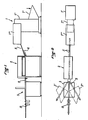
Les figures 1 et 2 montrent une chaîne de fabrication selon l'invention. Cette chaîne comporte, notamment, un appareil d'alimentation 1 des préformes, un appareil de chauffage 2 ou de réchauffage des préformes et un appareil de moulage par étirage-soufflage 3.Figures 1 and 2 show a production line according to the invention. This chain comprises, in particular, a
L'appareil d'alimentation 1 comporte un moyen de chargement 1′, pour charger en vrac, manuellement ou automatiquement des préformes préfabriquées, un moyen d'élévation 1˝ desdites préformes et un moyen de redressement et de distribution 1‴ de celles-ci.The
Le moyens de chargement 1′ peut être sous forme, par exemple, d'une trémie, le moyen d'élévation peut être sous forme d'un tapis élévateur et le moyen de redressement et de distribution peut comporter, par exemple, une table vibrante ou un autre moyen. On peut noter dès à présent, que l'appareil d'alimentation 1, tel que décrit ci-avant, est prévu pour des préformes refroidies après fabrication (généralement moulées par injection), mais il peut être envisagé d'utiliser directement des préformes encore chaudes provenant de fabrication, auquel cas les moyens 1′ et 1˝ sont supprimés, les préformes étant directement réceptionnées par le moyen 1‴.The loading means 1 ′ can be in the form, for example, of a hopper, the lifting means can be in the form of a lifting belt and the straightening and distribution means can comprise, for example, a vibrating table or some other way. It can now be noted that the
L'appareil d'alimentation 1 est prévu de manière telle que les préformes schématisées en 4 sur les figures 1, 3 et 4 comportent une paire de rails 5 inclinés, prévus pour l'évacuation desdites préformes par gravité vers l'appareil de chauffage 2.The
Comme le montrent plus particulièrement les figures 3 et 4, chaque préforme se présente sous la forme d'un tube bouché à une extrémité et comportant à son autre extrémité ouverte, une bague 6 filetée ou non et une contre-bague 7, sous forme d'une colerette en saillie. La bague 6 et la contre-bague 7 de la préforme constituent une partie définitive que l'on retrouve intacte pour former le col de chaque produit fini, c'est-à-dire de chaque bouteille qui sort de l'appareil de moulage 3, ces bouteilles étant schématisées en 8 sur les figures 1 et 2. C'est par la contre-bague 7 que chaque préforme 4 peut glisser sur la paire de rails 5 aménagés entre l'appareil 1 et l'appareil 2, son extrémité ouverte étant dirigée vers le haut. Toutefois, en l'absence de contre-bague 7, chaque préforme peut glisser par sa bague 6. A la sortie de l'appareil 2, une même paire de rails 5 permet de transférer les préformes dudit appareil 2 vers l'appareil 3. Sur la figure 2, on peut constater qu'au lieu et place de l'appareil 3, il peut parfaitement être prévu, par exemple, deux appareils du même type 3′ et 3˝ vers lesquels les préformes sont dirigées alternativement. A la sortie de l'appareil 3 ou des appareils 3′ et 3˝, les préformes ont été étirées-soufflées pour donner des produits finis tels que les bouteilles 8 déjà citées. Comme le montrent en outre les figures 1 et 2, les bouteilles 8 peuvent être transférées sur une paire de rails en glissant par la contre-bague de leur col vers un ou plusieurs autres postes disposés en aval de la chaîne représentée, tel par exemple qu'un poste de mise en place d'un fond.As shown more particularly in Figures 3 and 4, each preform is in the form of a tube plugged at one end and having at its other open end, a
La paire de rails 5 disposée d'une part, entre l'appareil d'alimentation 1 et l'appareil de chauffage 2 et, d'autre part, en aval dudit appareil 2 se retrouve à l'intérieur de ce dernier, comme le montrent plus particulièrement les figures 3 et 4.The pair of
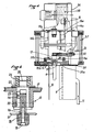
L'appareil de chauffage 2 est destiné, comme déjà dit, à réchauffer les préformes jusqu'à une température adéquate en vue de préparer le moulage par étirage-soufflage, lequel est effectué dans l'appareil 3. Pour ce faire, les préformes doivent passer dans un four. Le four est, par exemple, constitué de manière connue par une rampe 9 de tubes émetteurs de rayons infrarouges, par un réflecteur 10 de rayons infrarouges et par un dispositif de ventilation schématisé par une canalisation de soufflage 11 (figure 4).The
Les préformes arrivent dans l'appareil de chauffage 2 par un poste d'entrée muni de glissières 5′ faisant en quelque sorte la jonction entre les rails de l'appareil 1 et ceux de l'appareil 2, et d'un distributeur, schématisé en 12 sur la figure 3. Le distributeur 12 est destiné à distribuer les préformes provenant de l'appareil 1, au fur et à mesure de l'avancement d'un moyen d'entraînement desdites préformes, dont il sera question ci-après. Les préformes sortent de l'appareil 2 par un poste de sortie muni de glissières 5˝ qui sont en continuité avec les rails 5.The preforms arrive in the
Le dispositif d'entraînement des préformes comporte une pluralité de doigts, tels que 13, comme le montrent la figure 3 et plus en détail la figure 5.The preform driving device comprises a plurality of fingers, such as 13, as shown in FIG. 3 and in more detail in FIG. 5.
Les doigts 13 sont mûs par un dispositif d'entraînement qui comporte quatre roues dentées, telles que 14a et 14b sur la figure 4 (les deux autres roues, non visibles sur cette figure), étant disposées à l'autre extrémité de l'appareil de chauffage) et deux chaînes sans fin, telles que schématisées en 15a et 15b sur la figure 4 (et en pointillés en ce qui concerne la chaîne 15a, sur la figure 3). Les chaînes 15a et 15b sont montées de manière à être mûes, au moyen d'un moteur 16, selon deux plans sensiblement verticaux et de façon à avoir au moins leurs brins inférieurs rectilignes et parallèles aux rails 5, comme le montre la figure 3.The
Les doigts 13 sont montés sur les chaînes 15a et 15b au moyen de supports sous forme de plaquettes 17 dont ils sont munis (figures 4 et 5). Comme le montre plus particulièrement la figure 5, chaque doigt 13 comporte, outre la plaquette 17 dont il vient d'être question, un embout tronconique 18 fixé par une vis 19 à un piston 20 entre lesquels est disposée une rondelle 21.The
Le piston 20 est monté coulissant dans un axe 22 de telle sorte qu'il puisse se mouvoir axialement dans celui-ci entre au moins deux positions déterminées par une goupille 23 et une cavité 24 aménagée dans ledit axe 22.The
La goupille 23 et la lumière 24 sont telles que le piston 20 peut avoir un mouvement axial tout en restant solidaire en rotation dudit axe 22. Comme le montre encore la figure 5, l'axe 22 est solidaire d'un pignon 25 fixé à celui-ci par une goupille 26, le pignon 25 étant aménagé au-dessus de la plaquette 17 par l'intermédiaire d'au moins une rondelle 27.The
Comme on peut le voir sur les figures 3 et 4, chaque doigt 13 est fixé sur les chaînes 15a et 15b de manière à avoir son embout mobile 18 tourné vers l'extérieur de telle sorte que par gravité, celui-ci a tendance à prendre sa position la plus ressortie vers l'extérieur dans la partie inférieure de sa trajectoire et au contraire, sa position la plus rentrée dans la partie supérieure. Toutefois, il est possible de prévoir un ressort pour solliciter en permanence l'embout vers sa position la plus ressortie.As can be seen in Figures 3 and 4, each
Le poste d'entrée de l'appareil 2 présente une came 28 et le poste de sortie une came 29 (figure 3).The inlet station of the
Les cames 28 et 29 sont prévues pour soulever et/ou maintenir en partie soulevés les embouts 18 des doigts 13, en agissant sur les rondelles 21 (figure 5) aux postes respectivement d'entrée et de sortie, comme le montre la figure 3.The
De la sorte, en coopération avec le distributeur 12, chaque doigt 13 arrive en fin de course de la came 28 juste au-dessus d'une préforme et son embout 18 vient s'introduire par gravité dans la partie ouverte de ladite préforme.In this way, in cooperation with the
Au poste de sortie, la came 29 soulève au contraire l'embout 18 pour libérer la préforme qui est évacuée par tout moyen de reprise tel que, par exemple le bras 30 représenté sur la figure 3.At the exit station, the
Afin d'obtenir un guidage parfait et ferme des doigts 13, au moins dans la partie de transport des préformes, l'appareil 2 est pourvu de glissières de guidage 31a, 31b rainurées de manière à guider et maintenir les plaquettes 17 des doigts 13 (figure 4).In order to obtain perfect and firm guidance of the
Les préformes qui défilent dans le four à rayons infrarouges (9 à 11) sont de préférence entraînées en rotation pendant le mouvement translatif au moyen, par exemple, d'une courroie crantée 32 entraînée par un arbre moteur 33 et qui vient s'engrener avec les pignons 25 (figure 5) des doigts 13. De la sorte, les axes 22 entraînent en rotation les embouts 18 (figure 5), qui eux-mêmes entraînent les préformes.The preforms which pass through the infrared ray oven (9 to 11) are preferably rotated during the translational movement by means, for example, of a
Comme le montre bien la figure 4, le four (9 à 11) agit sur les préformes, à l'exception de leurs bagues 6 et contre-bagues 7, les rails 5 définissant un plan au-dessus duquel il n'est pas souhaitable et il est même déconseillé d'avoir une chaleur excessive.As shown in Figure 4, the oven (9 to 11) acts on the preforms, with the exception of their
C'est pourquoi l'invention prévoit au niveau des rails 5, un écran thermique 34 et de façon tout à fait originale, des tubes 35a, 35b (figures 3 et 4), dont la base se trouve au niveau des rails 5 et qui s'étendent le long desdits rails de manière à encadrer de part et d'autre les bagues 6 des préformes 4.This is why the invention provides at the level of the
Dans les tubes 35a, 35b est prévue une circulation d'eau afin de refroidir cette partie.In the
En fait les rails 5 et les tubes 35a, 35b peuvent bien sûr être d'une seule pièce.In fact the
Toujours dans le but de séparer la partie four qui est ventilée, comme déjà dit, de la partie supérieure qui doit rester plus froide, l'invention prévoit de fermer ladite partie supérieure, par exemple par un capot 36 et des portes coulissantes 37 et de prévoir un ventilateur 38 (figures 3 et 4) de manière à créer au-dessus du plan défini par les rails 5, une ventilation dirigée vers le bas.Still with the aim of separating the oven part which is ventilated, as already said, from the upper part which must remain cooler, the invention provides for closing said upper part, for example by a
L'invention n'est pas limitée aux appareils décrits et il est bien sûr possible d'y incorporer des appareils en amont et en aval de ceux décrits ci-avant.The invention is not limited to the devices described and it is of course possible to incorporate devices upstream and downstream from those described above.
La sortie de l'appareil de chauffage 2 comportant des rails, les préformes sont amenées de préférence jusque dans l'appareil 3 en glissant aussi sur des rails, mais il est possible de reprendre les préformes par des pinces par exemple, destinées à venir prendre les préformes à la sortie de l'appareil 2 pour les placer dans l'appareil 3.The outlet of the
Claims (10)
Priority Applications (1)
| Application Number | Priority Date | Filing Date | Title |
|---|---|---|---|
| AT89403253T ATE86177T1 (en) | 1988-12-02 | 1989-11-24 | AUTOMATED PRODUCTION LINE FOR MANUFACTURING HOLLOW PLASTIC BODY. |
Applications Claiming Priority (2)
| Application Number | Priority Date | Filing Date | Title |
|---|---|---|---|
| FR8815811A FR2639869B1 (en) | 1988-12-02 | 1988-12-02 | AUTOMATED PLASTIC HOLLOW BODY MANUFACTURING CHAIN |
| FR8815811 | 1988-12-02 |
Publications (2)
| Publication Number | Publication Date |
|---|---|
| EP0377353A1 true EP0377353A1 (en) | 1990-07-11 |
| EP0377353B1 EP0377353B1 (en) | 1993-03-03 |
Family
ID=9372518
Family Applications (1)
| Application Number | Title | Priority Date | Filing Date |
|---|---|---|---|
| EP89403253A Expired - Lifetime EP0377353B1 (en) | 1988-12-02 | 1989-11-24 | Automated production line for making hollow plastic articles |
Country Status (5)
| Country | Link |
|---|---|
| EP (1) | EP0377353B1 (en) |
| AT (1) | ATE86177T1 (en) |
| DE (1) | DE68905172T2 (en) |
| ES (1) | ES2038839T3 (en) |
| FR (1) | FR2639869B1 (en) |
Cited By (6)
| Publication number | Priority date | Publication date | Assignee | Title |
|---|---|---|---|---|
| FR2675481A1 (en) * | 1991-04-16 | 1992-10-23 | Sidel Sa | AGENCY PREFORM CONVEYING DEVICE FOR ELIMINATING NESTED PREFORMS INTO OTHERS. |
| FR2720681A1 (en) * | 1994-06-03 | 1995-12-08 | Sidel Sa | Spinner and machine for manufacturing containers from preforms using at least one such spinner. |
| WO2002066231A1 (en) * | 2001-02-21 | 2002-08-29 | Stulic Miroslav | Transporting means to transport injection moulded preforms through a blow moulding apparatus |
| WO2002007021A3 (en) * | 2000-07-10 | 2003-10-02 | Bybox Holdings Ltd | System and method for facilitating receipt and collection of goods ordered from online retailers |
| FR3027886A1 (en) * | 2014-11-03 | 2016-05-06 | Sidel Participations | "DEVICE FOR TRANSPORTING PREFORMS IN A THERMAL CONDITIONING OVEN" |
| WO2020152417A1 (en) * | 2019-01-24 | 2020-07-30 | Tiama | Method and device for conveying containers in a suspended position |
Families Citing this family (4)
| Publication number | Priority date | Publication date | Assignee | Title |
|---|---|---|---|---|
| DE19757818A1 (en) | 1997-12-24 | 1999-07-01 | Krupp Corpoplast Masch | Process for tempering preforms and device for tempering |
| DE19825874A1 (en) * | 1998-06-10 | 1999-12-16 | Krones Ag | Method and device for the production of hollow plastic bodies |
| DE102006055963B4 (en) * | 2006-11-24 | 2016-10-27 | Sidel Participations S.A.S. | Device for transferring hollow cylindrical objects |
| DE102016001630A1 (en) | 2016-02-15 | 2017-08-17 | Khs Corpoplast Gmbh | A heating device for the thermal conditioning of preforms intended for blow molding |
Citations (9)
| Publication number | Priority date | Publication date | Assignee | Title |
|---|---|---|---|---|
| DE602672C (en) * | 1933-01-24 | 1934-09-14 | Axel Leonard Andersson | Bottle washing machine |
| US4116325A (en) * | 1976-03-18 | 1978-09-26 | Cincinnati Milacron Inc. | Conveyor combined with coupling for handling workpiece |
| FR2424120A1 (en) * | 1978-04-24 | 1979-11-23 | Yoshino Kogyosho Co Ltd | DEVICE FOR SUPPLYING PARTS OF A MACHINE BY BLOWING |
| GB2025348A (en) * | 1978-07-13 | 1980-01-23 | Yoshino Kogyosho Co Ltd | Device for conveying moulded pieces |
| US4313720A (en) * | 1980-03-03 | 1982-02-02 | Emhart Industries, Inc. | Parison transfer means |
| GB2097322A (en) * | 1981-04-24 | 1982-11-03 | Cincinnati Milacron Inc | Blow moulding |
| EP0070931A1 (en) * | 1978-11-16 | 1983-02-09 | THE MOTCH & MERRYWEATHER MACHINERY COMPANY | Air conveyor for bottle members |
| GB2116106A (en) * | 1982-03-05 | 1983-09-21 | Cincinnati Milacron Inc | Dielectric heating apparatus |
| US4694951A (en) * | 1985-10-04 | 1987-09-22 | Cincinnati Milacron Inc. | Bottom loader for a conveyor means |
-
1988
- 1988-12-02 FR FR8815811A patent/FR2639869B1/en not_active Expired - Lifetime
-
1989
- 1989-11-24 ES ES198989403253T patent/ES2038839T3/en not_active Expired - Lifetime
- 1989-11-24 AT AT89403253T patent/ATE86177T1/en not_active IP Right Cessation
- 1989-11-24 EP EP89403253A patent/EP0377353B1/en not_active Expired - Lifetime
- 1989-11-24 DE DE8989403253T patent/DE68905172T2/en not_active Expired - Fee Related
Patent Citations (9)
| Publication number | Priority date | Publication date | Assignee | Title |
|---|---|---|---|---|
| DE602672C (en) * | 1933-01-24 | 1934-09-14 | Axel Leonard Andersson | Bottle washing machine |
| US4116325A (en) * | 1976-03-18 | 1978-09-26 | Cincinnati Milacron Inc. | Conveyor combined with coupling for handling workpiece |
| FR2424120A1 (en) * | 1978-04-24 | 1979-11-23 | Yoshino Kogyosho Co Ltd | DEVICE FOR SUPPLYING PARTS OF A MACHINE BY BLOWING |
| GB2025348A (en) * | 1978-07-13 | 1980-01-23 | Yoshino Kogyosho Co Ltd | Device for conveying moulded pieces |
| EP0070931A1 (en) * | 1978-11-16 | 1983-02-09 | THE MOTCH & MERRYWEATHER MACHINERY COMPANY | Air conveyor for bottle members |
| US4313720A (en) * | 1980-03-03 | 1982-02-02 | Emhart Industries, Inc. | Parison transfer means |
| GB2097322A (en) * | 1981-04-24 | 1982-11-03 | Cincinnati Milacron Inc | Blow moulding |
| GB2116106A (en) * | 1982-03-05 | 1983-09-21 | Cincinnati Milacron Inc | Dielectric heating apparatus |
| US4694951A (en) * | 1985-10-04 | 1987-09-22 | Cincinnati Milacron Inc. | Bottom loader for a conveyor means |
Cited By (11)
| Publication number | Priority date | Publication date | Assignee | Title |
|---|---|---|---|---|
| FR2675481A1 (en) * | 1991-04-16 | 1992-10-23 | Sidel Sa | AGENCY PREFORM CONVEYING DEVICE FOR ELIMINATING NESTED PREFORMS INTO OTHERS. |
| EP0511048A1 (en) * | 1991-04-16 | 1992-10-28 | Sidel | Transporting device for preforms adapted for removing nested preforms |
| US5186307A (en) * | 1991-04-16 | 1993-02-16 | Sidel | Transport device for removing interlocked preforms |
| FR2720681A1 (en) * | 1994-06-03 | 1995-12-08 | Sidel Sa | Spinner and machine for manufacturing containers from preforms using at least one such spinner. |
| WO1995033616A1 (en) * | 1994-06-03 | 1995-12-14 | Sidel S.A. | Rapidly interchangeable transport mandrel for container preforms and use of such mandrel |
| WO2002007021A3 (en) * | 2000-07-10 | 2003-10-02 | Bybox Holdings Ltd | System and method for facilitating receipt and collection of goods ordered from online retailers |
| WO2002066231A1 (en) * | 2001-02-21 | 2002-08-29 | Stulic Miroslav | Transporting means to transport injection moulded preforms through a blow moulding apparatus |
| FR3027886A1 (en) * | 2014-11-03 | 2016-05-06 | Sidel Participations | "DEVICE FOR TRANSPORTING PREFORMS IN A THERMAL CONDITIONING OVEN" |
| WO2020152417A1 (en) * | 2019-01-24 | 2020-07-30 | Tiama | Method and device for conveying containers in a suspended position |
| FR3092099A1 (en) * | 2019-01-24 | 2020-07-31 | Tiama | Method and device for conveying containers in suspended position |
| US11623827B2 (en) | 2019-01-24 | 2023-04-11 | Tiama | Method and device for conveying containers in a suspended position |
Also Published As
| Publication number | Publication date |
|---|---|
| DE68905172D1 (en) | 1993-04-08 |
| FR2639869A1 (en) | 1990-06-08 |
| DE68905172T2 (en) | 1993-07-15 |
| EP0377353B1 (en) | 1993-03-03 |
| ES2038839T3 (en) | 1993-08-01 |
| FR2639869B1 (en) | 1991-03-22 |
| ATE86177T1 (en) | 1993-03-15 |
Similar Documents
| Publication | Publication Date | Title |
|---|---|---|
| EP0640035B1 (en) | Machine for blow moulding hollow objects | |
| EP0812254B1 (en) | Apparatus for making containers by blow-moulding plastic parisons | |
| FR2484905A1 (en) | METHOD FOR MOLDING ARTICLES BY BLOWING | |
| EP0377353B1 (en) | Automated production line for making hollow plastic articles | |
| US4690633A (en) | Apparatus for preparing hollow plastic articles | |
| EP0713758B1 (en) | Apparatus and method of molding heat-resistant containers | |
| ES2230427T3 (en) | TUNNEL SPHORNO TO OBTAIN PACKS OF THERMOCONTRACTION MATERIALS AND PACKAGING PROCEDURE AS EFFECTED. | |
| FR2479077A1 (en) | INSTALLATION FOR MANUFACTURING HOLLOW BODIES THROUGH PACKAGING THEN BLOWING PREFORMS OF PLASTIC MATERIAL | |
| EP0026895A1 (en) | Apparatus for producing containers by stretch-blowing plastics parisons | |
| FR2515101A1 (en) | MACHINE FOR PRODUCING BIAXIALLY ORIENTED ARTICLES FROM THERMOPLASTIC PREFORMS | |
| WO1995005933A1 (en) | Apparatus for making containers by blow-moulding plastic parisons | |
| CA1106118A (en) | Method and apparatus for producing thermoplastic hallow bodies | |
| WO2005065917A1 (en) | Furnace for heating a preform, provided with two cooling fans | |
| US8465274B2 (en) | Moulding unit for a plant for blow-moulding plastic containers, particularly bottles | |
| EP0998382B1 (en) | Method and installation for making containers by blowing thermoplastic blanks | |
| FR2521480A1 (en) | APPARATUS FOR AUTOMATIC FEEDING OF PLASTIC MATERIAL FOR THE MANUFACTURE OF HOLLOW BODIES | |
| CH629154A5 (en) | APPARATUS FOR TRANSFERRING PARTS BETWEEN AN INJECTION PRESS AND A STRETCH-BLOWING MACHINE. | |
| US4357788A (en) | Method and apparatus for assembling tubular sleeve preforms and containers | |
| US3765813A (en) | Blow molding apparatus | |
| EP0069007B1 (en) | Method of producing blow-stretched plastics containers, and apparatus for carrying out the method | |
| US3932095A (en) | Blow molding apparatus | |
| JPH0550976B2 (en) | ||
| CH629699A5 (en) | Installation for manufacturing biaxially-oriented plastic articles and mandrel for the installation | |
| EP1660371B1 (en) | Thermoplastic bottle-forming and -filling method and installation | |
| CH618941A5 (en) |
Legal Events
| Date | Code | Title | Description |
|---|---|---|---|
| PUAI | Public reference made under article 153(3) epc to a published international application that has entered the european phase |
Free format text: ORIGINAL CODE: 0009012 |
|
| AK | Designated contracting states |
Kind code of ref document: A1 Designated state(s): AT DE ES GB IT NL |
|
| 17P | Request for examination filed |
Effective date: 19901106 |
|
| 17Q | First examination report despatched |
Effective date: 19920421 |
|
| ITF | It: translation for a ep patent filed |
Owner name: LENZI & C. |
|
| GRAA | (expected) grant |
Free format text: ORIGINAL CODE: 0009210 |
|
| AK | Designated contracting states |
Kind code of ref document: B1 Designated state(s): AT DE ES GB IT NL |
|
| REF | Corresponds to: |
Ref document number: 86177 Country of ref document: AT Date of ref document: 19930315 Kind code of ref document: T |
|
| REF | Corresponds to: |
Ref document number: 68905172 Country of ref document: DE Date of ref document: 19930408 |
|
| GBT | Gb: translation of ep patent filed (gb section 77(6)(a)/1977) |
Effective date: 19930311 |
|
| REG | Reference to a national code |
Ref country code: ES Ref legal event code: FG2A Ref document number: 2038839 Country of ref document: ES Kind code of ref document: T3 |
|
| PLBE | No opposition filed within time limit |
Free format text: ORIGINAL CODE: 0009261 |
|
| STAA | Information on the status of an ep patent application or granted ep patent |
Free format text: STATUS: NO OPPOSITION FILED WITHIN TIME LIMIT |
|
| 26N | No opposition filed | ||
| ITTA | It: last paid annual fee | ||
| REG | Reference to a national code |
Ref country code: GB Ref legal event code: IF02 |
|
| PGFP | Annual fee paid to national office [announced via postgrant information from national office to epo] |
Ref country code: GB Payment date: 20061116 Year of fee payment: 18 |
|
| PGFP | Annual fee paid to national office [announced via postgrant information from national office to epo] |
Ref country code: NL Payment date: 20071130 Year of fee payment: 19 Ref country code: ES Payment date: 20071126 Year of fee payment: 19 |
|
| PGFP | Annual fee paid to national office [announced via postgrant information from national office to epo] |
Ref country code: IT Payment date: 20071127 Year of fee payment: 19 Ref country code: AT Payment date: 20071128 Year of fee payment: 19 |
|
| PGFP | Annual fee paid to national office [announced via postgrant information from national office to epo] |
Ref country code: DE Payment date: 20080128 Year of fee payment: 19 |
|
| GBPC | Gb: european patent ceased through non-payment of renewal fee |
Effective date: 20071124 |
|
| PG25 | Lapsed in a contracting state [announced via postgrant information from national office to epo] |
Ref country code: GB Free format text: LAPSE BECAUSE OF NON-PAYMENT OF DUE FEES Effective date: 20071124 |
|
| PG25 | Lapsed in a contracting state [announced via postgrant information from national office to epo] |
Ref country code: NL Free format text: LAPSE BECAUSE OF NON-PAYMENT OF DUE FEES Effective date: 20090601 |
|
| NLV4 | Nl: lapsed or anulled due to non-payment of the annual fee |
Effective date: 20090601 |
|
| PG25 | Lapsed in a contracting state [announced via postgrant information from national office to epo] |
Ref country code: IT Free format text: LAPSE BECAUSE OF NON-PAYMENT OF DUE FEES Effective date: 20081124 Ref country code: AT Free format text: LAPSE BECAUSE OF NON-PAYMENT OF DUE FEES Effective date: 20081124 |
|
| PG25 | Lapsed in a contracting state [announced via postgrant information from national office to epo] |
Ref country code: DE Free format text: LAPSE BECAUSE OF NON-PAYMENT OF DUE FEES Effective date: 20090603 |
|
| REG | Reference to a national code |
Ref country code: ES Ref legal event code: FD2A Effective date: 20081125 |
|
| PG25 | Lapsed in a contracting state [announced via postgrant information from national office to epo] |
Ref country code: ES Free format text: LAPSE BECAUSE OF NON-PAYMENT OF DUE FEES Effective date: 20081125 |