EP0383559A2 - Portable power supply - Google Patents
Portable power supply Download PDFInfo
- Publication number
- EP0383559A2 EP0383559A2 EP90301544A EP90301544A EP0383559A2 EP 0383559 A2 EP0383559 A2 EP 0383559A2 EP 90301544 A EP90301544 A EP 90301544A EP 90301544 A EP90301544 A EP 90301544A EP 0383559 A2 EP0383559 A2 EP 0383559A2
- Authority
- EP
- European Patent Office
- Prior art keywords
- body case
- power supply
- portable power
- major surfaces
- supply according
- Prior art date
- Legal status (The legal status is an assumption and is not a legal conclusion. Google has not performed a legal analysis and makes no representation as to the accuracy of the status listed.)
- Granted
Links
Images


Classifications
-
- H—ELECTRICITY
- H02—GENERATION; CONVERSION OR DISTRIBUTION OF ELECTRIC POWER
- H02J—CIRCUIT ARRANGEMENTS OR SYSTEMS FOR SUPPLYING OR DISTRIBUTING ELECTRIC POWER; SYSTEMS FOR STORING ELECTRIC ENERGY
- H02J7/00—Circuit arrangements for charging or depolarising batteries or for supplying loads from batteries
- H02J7/0042—Circuit arrangements for charging or depolarising batteries or for supplying loads from batteries characterised by the mechanical construction
-
- H—ELECTRICITY
- H01—ELECTRIC ELEMENTS
- H01M—PROCESSES OR MEANS, e.g. BATTERIES, FOR THE DIRECT CONVERSION OF CHEMICAL ENERGY INTO ELECTRICAL ENERGY
- H01M10/00—Secondary cells; Manufacture thereof
- H01M10/42—Methods or arrangements for servicing or maintenance of secondary cells or secondary half-cells
- H01M10/46—Accumulators structurally combined with charging apparatus
-
- H—ELECTRICITY
- H01—ELECTRIC ELEMENTS
- H01M—PROCESSES OR MEANS, e.g. BATTERIES, FOR THE DIRECT CONVERSION OF CHEMICAL ENERGY INTO ELECTRICAL ENERGY
- H01M50/00—Constructional details or processes of manufacture of the non-active parts of electrochemical cells other than fuel cells, e.g. hybrid cells
- H01M50/20—Mountings; Secondary casings or frames; Racks, modules or packs; Suspension devices; Shock absorbers; Transport or carrying devices; Holders
- H01M50/204—Racks, modules or packs for multiple batteries or multiple cells
- H01M50/207—Racks, modules or packs for multiple batteries or multiple cells characterised by their shape
- H01M50/213—Racks, modules or packs for multiple batteries or multiple cells characterised by their shape adapted for cells having curved cross-section, e.g. round or elliptic
-
- Y—GENERAL TAGGING OF NEW TECHNOLOGICAL DEVELOPMENTS; GENERAL TAGGING OF CROSS-SECTIONAL TECHNOLOGIES SPANNING OVER SEVERAL SECTIONS OF THE IPC; TECHNICAL SUBJECTS COVERED BY FORMER USPC CROSS-REFERENCE ART COLLECTIONS [XRACs] AND DIGESTS
- Y02—TECHNOLOGIES OR APPLICATIONS FOR MITIGATION OR ADAPTATION AGAINST CLIMATE CHANGE
- Y02E—REDUCTION OF GREENHOUSE GAS [GHG] EMISSIONS, RELATED TO ENERGY GENERATION, TRANSMISSION OR DISTRIBUTION
- Y02E60/00—Enabling technologies; Technologies with a potential or indirect contribution to GHG emissions mitigation
- Y02E60/10—Energy storage using batteries
-
- Y—GENERAL TAGGING OF NEW TECHNOLOGICAL DEVELOPMENTS; GENERAL TAGGING OF CROSS-SECTIONAL TECHNOLOGIES SPANNING OVER SEVERAL SECTIONS OF THE IPC; TECHNICAL SUBJECTS COVERED BY FORMER USPC CROSS-REFERENCE ART COLLECTIONS [XRACs] AND DIGESTS
- Y02—TECHNOLOGIES OR APPLICATIONS FOR MITIGATION OR ADAPTATION AGAINST CLIMATE CHANGE
- Y02E—REDUCTION OF GREENHOUSE GAS [GHG] EMISSIONS, RELATED TO ENERGY GENERATION, TRANSMISSION OR DISTRIBUTION
- Y02E60/00—Enabling technologies; Technologies with a potential or indirect contribution to GHG emissions mitigation
- Y02E60/16—Mechanical energy storage, e.g. flywheels or pressurised fluids
-
- Y—GENERAL TAGGING OF NEW TECHNOLOGICAL DEVELOPMENTS; GENERAL TAGGING OF CROSS-SECTIONAL TECHNOLOGIES SPANNING OVER SEVERAL SECTIONS OF THE IPC; TECHNICAL SUBJECTS COVERED BY FORMER USPC CROSS-REFERENCE ART COLLECTIONS [XRACs] AND DIGESTS
- Y10—TECHNICAL SUBJECTS COVERED BY FORMER USPC
- Y10S—TECHNICAL SUBJECTS COVERED BY FORMER USPC CROSS-REFERENCE ART COLLECTIONS [XRACs] AND DIGESTS
- Y10S224/00—Package and article carriers
- Y10S224/902—Battery carrier
-
- Y—GENERAL TAGGING OF NEW TECHNOLOGICAL DEVELOPMENTS; GENERAL TAGGING OF CROSS-SECTIONAL TECHNOLOGIES SPANNING OVER SEVERAL SECTIONS OF THE IPC; TECHNICAL SUBJECTS COVERED BY FORMER USPC CROSS-REFERENCE ART COLLECTIONS [XRACs] AND DIGESTS
- Y10—TECHNICAL SUBJECTS COVERED BY FORMER USPC
- Y10S—TECHNICAL SUBJECTS COVERED BY FORMER USPC CROSS-REFERENCE ART COLLECTIONS [XRACs] AND DIGESTS
- Y10S224/00—Package and article carriers
- Y10S224/929—Article carrier for electrical device
- Y10S224/93—Attached to animate bearer
Definitions
- the present invention relates to a portable power supply and, more specifically, to a portable power supply to be connected to electronic devices such as a handy game machine (commercially available by the name of "GAME BOY") employing dot matrix liquid crystal display screen.
- a handy game machine commercially available by the name of "GAME BOY”
- dot matrix liquid crystal display screen employing dot matrix liquid crystal display screen.
- a power supply for supplying power to various electric devices and electronic devices such as electric tools, video cameras and so on has a box-shaped body case containing batteries.
- Japanese Utility Model Laying Open No. 60-855 discloses a portable battery case.
- charging is done with the case body containing storage batteries attached to a charger, and after the charging is completed, it is detached from the charger, and a holder body having a hook is engaged so that power can be supplied to an electronic device while it is carried.
- battery case is used incorporated in or attached to the body of the electronic device to which the power is supplied.
- a storage battery is charged by connecting the same to a charger provided separately from the battery case, as shown in Japanese Utility Model Laying Open No. 56-61973 and in Japanese Utility Model Laying Open No. 56-166664, for example.
- Japanese Utility Model Laying Open No. 57-161768 discloses a packed power supply which is capable of both supplying power to electronic devices and of being charged from a commercial power source.
- the packed power supply contains a storage battery and a step-down transformer for supplying charging power to the storage battery.
- plugs are exposed to be inserted into receptacles, and after charging, the packed power supply is used incorporated in the body of the electronic device. Therefore, the packed power supply cannot supply power to an electronic device or the like while it is being charged.
- a space for accommodating the packed power supply must be provided in the electronic device, which prevents reduction in size of the electronic device.
- US Patent No. 3,919,615 discloses a power belt for carrying a portable power supply adapted to supply power to an electronic device while repeatedly charging the storage battery.
- the portable power supply comprises an input terminal which is connected to a commercial power source, an output terminal which is connected to an electronic device such as a video camera, the storage battery to be charged, and a charger, and the storage battery and the charger are electrically connected to each other through an external connecting cord. Therefore, the use of the portable power supply with the power supply attached to a human body is not very safe, since electric contact and the like between the storage battery and the connecting cord are exposed.
- a voltage lowering portion such as a step-down transformer or a transistor inverter is provided for supplying charging power to the storage battery by lowering the voltage of the commercial power source. It may be possible to attach the inverter unit to a human body while the power supply is connected to a commercial power source to charge the storage battery, enabling use of the electronic device. However, if the charging or power supply to the electronic device is carried out with the body case attached to one's body, the voltage lowering portion is considerably heated by the operation. Therefore, the user may feel uncomfortable or anxious, since his body (waist) touching the rear surface of the body case is heated by the heat radiation therefrom. The heat caused by the voltage lowering portion becomes more and more conspicuous as the volume of the body case becomes smaller and smaller, when a transistor inverter is used for the voltage lowering portion in order to minimize the portable power supply.
- a voltage lowering portion such as a step-down transformer or a transistor inverter is provided for supplying charging power to the storage battery by lowering the voltage of the commercial power
- a portable power supply as described above comprises an input portion connected to a commercial power source, and an output portion for supplying power of a storage battery to an electronic device or the like.
- a power supply is often used and treated while it is carried. Accordingly, when the power supply happens to fall on the floor, for example, the input portion or the output portion provided outside the body case may be damaged or deformed by the shock at the time of falling. This may cause troubles in connecting the power supply to the commercial power source or to electronic devices.
- One object of the present invention is to provide a portable power supply having superior safety capable of simultaneously supplying power and of being charged.
- Another object of the present invention is to provide a portable power supply capable of preventing influence of heat generated by voltage lowering portion on human body.
- a further object of the present invention is to provide a portable power supply in which an input portion and an output portion can be effectively protected from a shock when it falls.
- a portable power supply in accordance with one aspect of the present invention comprises a body case, an attaching portion, an input portion, a voltage lowering portion, a storage battery and an output portion.
- the attaching portion is for attaching the body case detachably to a human body.
- the input portion is provided exposed from the body case and it is connected to a commercial power source through a connecting cord.
- the voltage lowering portion is contained in the body case, and it lowers voltage of the power supplied from the input portion.
- the storage battery is contained in the body case and is charged by the output from the voltage lowering portion.
- the output portion is provided exposed from the body case, and it can be connected to a prescribed electronic device through a connecting cord, for supplying power charged in the storage battery.
- the storage battery is contained in the power supply, so that the electric contact portions for charging and for power supply are not externally exposed. Therefore, safety in charging and power supply can be improved.
- power can be supplied to an external electric device connected to the output portion with the storage battery being charged contained in the power supply. Therefore, power supply to the electronic device can be carried out simultaneously with the charging of the storage battery.
- the portable power supply is not used incorporated in or attached to the electronic device. Power is supplied to the electronic device through a connecting cord, while the power supply is carried separately from the electronic device. Therefore, it is convenient for supplying power to a small and compact electronic device.
- a portable power supply in accordance with another aspect of the present invention comprises a body case, an attaching portion, an input portion, a voltage lowering portion, a storage battery, an output portion and heat radiating means.
- the body case has two opposing wall surfaces.
- the attaching portion is provided on one of the wall surfaces of the body case for detachably attaching the body case to a human body.
- the heat radiating means is to improve heat radiation of one of the wall surfaces of the body case to be higher than that of the other one of the wall surfaces.
- the voltage lowering portion is heated as it operates, when power is supplied to an electronic device while charging the storage battery, with the power supply carried by the attaching portion attached to a belt at one's waist, for example.
- the heat radiation of the wall surface of the body case opposite to the attaching portion is provided is improved by the heat radiating means. Accordingly, heat from the voltage lowering portion is substantially radiated to outside from the wall surface of the body case opposite to the human body, and the heat radiation from the side in contact with the human body can be reduced. Therefore, the user is free from discomfort or anxiety caused by the transmission of heat from the voltage lowering portion to his body.
- a portable power supply in accordance with a further aspect of the present invention comprises a body case, an attaching portion, an input portion, a voltage lowering portion, a storage battery and an output portion.
- the body case has two sections divided by a prescribed reference line.
- the input portion is positioned on one of the wall surfaces of the body case (for example, lower portion when the case is attached to the human body by the attaching portion).
- the output portion is positioned on the other one of the wall surfaces of the body case (for example, upper portion when the case is attached to the human body by the attaching portion).
- the input and the output portions are provided in one of the two sections (e.g. left side).
- the voltage lowering portion which is heavy as it includes a transformer and the like, is contained in the other of the two sections (e.g. right side). Therefore, the center of gravity of the portable power supply is positioned in the other section, which is opposite to the section where the input and output portions are formed.
- the body case when the body case happens to fall on the floor or the like while it is carried, the body case falls inclined to the side of the other area at which the center of gravity exist. Consequently, an end portion opposite to the area at which input portion and the output portion are positioned hits the floor or the like at first. Consequently, the shock at falling is not directly applied to the input portion or to the output portion. Therefore, damage to the input portion or the output portion can be prevented, reducing possibility of short circuit or the like caused by the damage.
- the portable power supply 1 comprises a body case 2.
- the body case 2 is a box-shaped case consisted of two halves 2a and 2b joined together.
- Chargable batteries such as nickel cadmium (hereinafter referred to as storage batteries) 3 and a voltage lowering portion 4 consisted of a transformer or a transistor inverter are contained in the body case 2. More specifically, four storage batteries 3, for instance, are contained along the center line N.A on one side in the longitudinal direction of the body case 2 (e.g.
- An input portion 5 connected to a commercial power source is provided to be exposed on a prescribed surface, for example, lower end surface of the body case 2.
- An output portion 6 for supplying power charged in the storage batteries 3 to a prescribed electronic device (not shown) is provided to be exposed on the upper end surface of the body case 2.
- a terminal pin 5a for coupling a plug 7 connected to an AC power supply through a connecting cord is provided at the input portion 5.
- the plug portion 8a is connected to the output portion 6 through the connecting cord 8.
- the input portion 5 is provided on the left side of the center line N.A on lower end surface of the body case 2.
- the output portion 6 is provided on the left side of the center line N.A on the upper end surface of the body case 2.
- the relatively heavy voltage lowering portion 4 is contained biased to the right side of the center line N.A in the lower portion of the body case 2.
- a phantom line P connecting the input portion 5 and the output portion 6 is positioned on the left side of the center line N.A. Therefore, the center of gravity G of the body case 2 is biased the right side of the center line N.A. The center of gravity is further moved to the right when the body case is suspended by the cord 8.
- the body case 2 further contains a circuit board 10 including a charging circuit and the like.
- the body case is sealed by coupling the halves 2a and 2b by a coupling bolt 9.
- a hook shaped attaching portion 13 is provided on the rear surface of the body case 2.
- the hook shaped attaching portion 13 has a base end portion 13a provided projecting from the body case 2 and an engaging portion 13b bent toward the side of the body with only the tip end portion thereof bent outward from the body.
- the base end portion 13a is mounted on a mounting portion 14 by the coupling volt 9.
- the mounting portion 14 is a concave portion provided on the other end portion of the body case 2.
- Ribs 13c for preventing slip are provided on the surface of the attaching portion 13b.
- the attaching portion 13 is formed of a flexible material such as synthetic resin or metal thin plate. There is a space t between the engaging portion 13b and the rear surface of the body case 2.
- the attaching portion 13b is flexible to be bent to the side of the body case 2, with the base end portion 13a being the center.
- the attaching portion 13 is detachably attached to a waist A of a human body with the attaching portion 13 gripping a belt B.
- a plurality of concave grooves 15 are provided laterally on the surface of the body case 2 which corresponds to the position of the storage batteries 3 and of the voltage lowering portion 4.
- the concave grooves 15 are provided for effectively radiating heat caused by the operation of the voltage lowering portion 4 to the outside opposite to the waist A.
- the thickness of the wall portion of the half 2a on the surface side of the body case 2 can be made thin, and the heat radiating area can be enlarged. Therefore, the heat radiating function of the surface side of the body case 2 is significantly improved.
- the wall portion of the body case 2 is formed of synthetic resin, the heat conductivity is inversely proportional to the thickness of the wall portion.
- the heat conductivity is doubled when the thickness of the wall portion is reduced to one half.
- the surface area of the wall portion is enlarged. The heat radiating effect of the surface of the body case 2 can be further improved accordingly.
- the storage battery 3 and the voltage lowering portion 4 are arranged in contact with the inner surface of the surface side of the half 2a. Therefore, decrease of strength of the half 2a caused by the formation of the concave groove 15 is compensated for by the battery 3 and the voltage lowering portion 4, and at the same time, heat conductivity from the voltage lowering portion 4 to the half 2a is improved.
- the input portion 5 is connected to a primary side of the voltage lowering portion 4 formed of a transformer or the like.
- the positive and negative output ends of a plurality of storage batteries 3 are connected to a secondary side of the voltage lowering portion 4 through a rectifier 16.
- Charging and power supply to electronic device can be simultaneously carried out by supplying power to the output portion 6 while the batteries are charged by the output from the voltage lowering portion 4, in this manner.
- the portable power supply can be used as an AC adapter by connecting the input portion 5 to an AC power source and by connecting an electronic device to the output portion 6.
- this power supply 1 When this power supply 1 is to be used as a backup power supply, the power supply 1 is attached to one's body A by engaging the attaching portion 13 with a belt B. An electronic device is connected to the output portion 6 via the plug portion 8a, whereby power is supplied to the electronic device.
- the output of the storage battery 3 When the output of the storage battery 3 is reduced to be lower than a prescribed level as the batteries are discharged, the storage batteries 3 are charged by connecting the plug 7 to the input portion 5 and connecting a cord on the power source side to a commercial power source. In that case, as shown in Fig. 8, the power supply 1 may be detached from the human body and placed on the floor 20 or desk for charging.
- the storage batteries 3 are contained in the upper space of the body case 2, and the voltage lowering portion 4 is contained in the lower space of the body case 2, so that a space is surely provided between the waist A and the lower portion of the body case 2 where the voltage lowering portion 4 is contained.
- the heat from the voltage lowering portion 4 is hardly transmitted to the waist A.
- the storage batteries 3 are heavier than the voltage lowering portion 4, the lower portion of the body case 2 where the voltage lowering portion 4 is positioned does not come closer to the waist A. Accordingly, the body case 2 can be attached stably to the waist A of the human body by the attaching portion 13.
- the concave grooves 17 may be formed vertically as shown in Fig. 9A. By doing so, the heat tends to escape upward along the direction of the concave grooves.
- a plurality of spots 18 may be provided as shown in Fig. 9B.
- the thickness D1 of the wall surface on the rear side of the body case 2 may be made thicker and the thickness D2 of the wall surface of the surface side may be made thin.
- a heat radiating plate or material 19 having high heat conductivity may be provided on the wall surface portion of the body case 2 facing the voltage lowering portion 4.
- the heat radiating plate 19 is formed by mixing powder materials having high heat conductivity such as aluminum, copper, zinc or the like in a synthetic resin.
- Fig. 11 is a cross sectional view showing another embodiment of the present invention.
- positions of the storage batteries 3 and the voltage lowering portion 4 are selected to be inverted in the up and down directions.
- the attaching portion 13 is provided on the wall surface of the rear surface of the body case 2 facing the voltage lowering portion 4.
- a space T is surely provided between the waist A and the body case 2, as the attaching portion 13 engaged with the belt B serves as a spacer. Therefore, even if the heat from the voltage lowering portion 4 is transmitted to the rear surface of the body case 2, the heat is emitted from the space T to the side, and the heat is hardly transmitted to the waist A.
- the storage batteries 3 heavier than the voltage lowering portion 4 are positioned on the lower portion of the body case 2. Therefore, even if the lower portion of the body case 2 where the storage batteries 3 are contained comes near to the waist A, the heat radiating path from the voltage lowering portion 4 is not obstructed, and heat is not transmitted to the waist A.
- the portable power supply 1 may happen to fall when the attaching portion 13 is engaged with or detached from the belt B or when it is carried.
- the positional relation between respective portion is set such that the center of gravity G of the power supply 1 is positioned on the right side (i.e. opposite to the position of formation of the output portion 5) of the center line N.A, as shown in Fig. 2. Therefore, if the power supply 1 falls, the body case 2 falls inclined to the side of the center of gravity G, as shown in Fig. 12. Accordingly, an end portion K opposite to the input portion 5 first hits the floor 20. Namely, the input portion 5 provided on an end portion opposite to the end portion K can be prevented from first hitting the floor, whereby the damage to the input portion 5 can be prevented. Even when the power supply 1 falls with the output portion 6 facing downward, the output portion 6 can be protected from the shock of falling from the same reason.
- the input portion may be formed of a charging plug blade retractable from the side surface of the body case 2.
- noise preventing means may be provided at the connecting portion on the side of the electronic device.
- the noise preventing means is unnecessary.
- provision of such a noise preventing means increases cost of the electronic device.
- the provision of the noise preventing means increases the size of the electronic device, making it inconvenient to carry the electronic device.
- an output plug portion 8a such as shown in Fig. 13 is employed.
- Noise preventing means is provided at the plug portion 8a.
- the connecting code 8 is shielded.
- Tip ends of a core 81 and a shield 82 are wound four times over positions symmetrical to each other by the angle of 180° of the ferrite core 83, respectively, and are connected to pin portions 84 and 85 of the plug portion 8a.
- the ferrite core 83 is a ring formed of Ni-Zn material.
- the plug portion 8a processed in this manner is covered by insert molding, using vinyl chloride resin.
- Fig. 14 is an equivalent circuit diagram with the plug portion 8a formed as shown in Fig. 13.
- the impedance on the side of the pin portions 84 and 85 should preferably be no less than 200 ⁇ , when a signal of 30 MHz is applied.
- the ferrite core 83 When the ferrite core 83 is arranged in a direction orthogonal to the direction of attachment/detachment of the plug portion 8a, the ferrite core 83 also serves as a reinforcement of the structure of the plug portion 8a. Accordingly, even when the plug portion 8a is coated and insert molded by a soft synthetic resin, it well withstands the force gripping the plug 8a when it is attached/detached. Accordingly, breaking between the core 81, the shield 82 and the pin portions 84 and 85 can be reduced, since unnecessary deformation is prevented.
Abstract
Description
- The present invention relates to a portable power supply and, more specifically, to a portable power supply to be connected to electronic devices such as a handy game machine (commercially available by the name of "GAME BOY") employing dot matrix liquid crystal display screen.
- Generally, a power supply for supplying power to various electric devices and electronic devices such as electric tools, video cameras and so on has a box-shaped body case containing batteries.
- For example, Japanese Utility Model Laying Open No. 60-855 discloses a portable battery case. In this battery case, charging is done with the case body containing storage batteries attached to a charger, and after the charging is completed, it is detached from the charger, and a holder body having a hook is engaged so that power can be supplied to an electronic device while it is carried. Sometimes, such battery case is used incorporated in or attached to the body of the electronic device to which the power is supplied. A storage battery is charged by connecting the same to a charger provided separately from the battery case, as shown in Japanese Utility Model Laying Open No. 56-61973 and in Japanese Utility Model Laying Open No. 56-166664, for example.
- Japanese Utility Model Laying Open No. 57-161768 discloses a packed power supply which is capable of both supplying power to electronic devices and of being charged from a commercial power source. The packed power supply contains a storage battery and a step-down transformer for supplying charging power to the storage battery. In charging, plugs are exposed to be inserted into receptacles, and after charging, the packed power supply is used incorporated in the body of the electronic device. Therefore, the packed power supply cannot supply power to an electronic device or the like while it is being charged. In addition, since power supply to an electronic device is done when the power supply is incorporated in or attached to the device, a space for accommodating the packed power supply must be provided in the electronic device, which prevents reduction in size of the electronic device.
- In view of the foregoing, US Patent No. 3,919,615 discloses a power belt for carrying a portable power supply adapted to supply power to an electronic device while repeatedly charging the storage battery. The portable power supply comprises an input terminal which is connected to a commercial power source, an output terminal which is connected to an electronic device such as a video camera, the storage battery to be charged, and a charger, and the storage battery and the charger are electrically connected to each other through an external connecting cord. Therefore, the use of the portable power supply with the power supply attached to a human body is not very safe, since electric contact and the like between the storage battery and the connecting cord are exposed.
- In an inverter unit 80 of the above described power belt, a voltage lowering portion such as a step-down transformer or a transistor inverter is provided for supplying charging power to the storage battery by lowering the voltage of the commercial power source. It may be possible to attach the inverter unit to a human body while the power supply is connected to a commercial power source to charge the storage battery, enabling use of the electronic device. However, if the charging or power supply to the electronic device is carried out with the body case attached to one's body, the voltage lowering portion is considerably heated by the operation. Therefore, the user may feel uncomfortable or anxious, since his body (waist) touching the rear surface of the body case is heated by the heat radiation therefrom. The heat caused by the voltage lowering portion becomes more and more conspicuous as the volume of the body case becomes smaller and smaller, when a transistor inverter is used for the voltage lowering portion in order to minimize the portable power supply.
- A portable power supply as described above comprises an input portion connected to a commercial power source, and an output portion for supplying power of a storage battery to an electronic device or the like. Such a power supply is often used and treated while it is carried. Accordingly, when the power supply happens to fall on the floor, for example, the input portion or the output portion provided outside the body case may be damaged or deformed by the shock at the time of falling. This may cause troubles in connecting the power supply to the commercial power source or to electronic devices.
- One object of the present invention is to provide a portable power supply having superior safety capable of simultaneously supplying power and of being charged.
- Another object of the present invention is to provide a portable power supply capable of preventing influence of heat generated by voltage lowering portion on human body.
- A further object of the present invention is to provide a portable power supply in which an input portion and an output portion can be effectively protected from a shock when it falls.
- A portable power supply in accordance with one aspect of the present invention comprises a body case, an attaching portion, an input portion, a voltage lowering portion, a storage battery and an output portion. The attaching portion is for attaching the body case detachably to a human body. The input portion is provided exposed from the body case and it is connected to a commercial power source through a connecting cord. The voltage lowering portion is contained in the body case, and it lowers voltage of the power supplied from the input portion. The storage battery is contained in the body case and is charged by the output from the voltage lowering portion. The output portion is provided exposed from the body case, and it can be connected to a prescribed electronic device through a connecting cord, for supplying power charged in the storage battery.
- In the portable power supply in accordance with one aspect of the present invention, the storage battery is contained in the power supply, so that the electric contact portions for charging and for power supply are not externally exposed. Therefore, safety in charging and power supply can be improved. In addition, power can be supplied to an external electric device connected to the output portion with the storage battery being charged contained in the power supply. Therefore, power supply to the electronic device can be carried out simultaneously with the charging of the storage battery. In addition, the portable power supply is not used incorporated in or attached to the electronic device. Power is supplied to the electronic device through a connecting cord, while the power supply is carried separately from the electronic device. Therefore, it is convenient for supplying power to a small and compact electronic device.
- A portable power supply in accordance with another aspect of the present invention comprises a body case, an attaching portion, an input portion, a voltage lowering portion, a storage battery, an output portion and heat radiating means. The body case has two opposing wall surfaces. The attaching portion is provided on one of the wall surfaces of the body case for detachably attaching the body case to a human body. The heat radiating means is to improve heat radiation of one of the wall surfaces of the body case to be higher than that of the other one of the wall surfaces.
- In the portable power supply in accordance with this another aspect of the present invention, the voltage lowering portion is heated as it operates, when power is supplied to an electronic device while charging the storage battery, with the power supply carried by the attaching portion attached to a belt at one's waist, for example. However, the heat radiation of the wall surface of the body case opposite to the attaching portion is provided is improved by the heat radiating means. Accordingly, heat from the voltage lowering portion is substantially radiated to outside from the wall surface of the body case opposite to the human body, and the heat radiation from the side in contact with the human body can be reduced. Therefore, the user is free from discomfort or anxiety caused by the transmission of heat from the voltage lowering portion to his body.
- A portable power supply in accordance with a further aspect of the present invention comprises a body case, an attaching portion, an input portion, a voltage lowering portion, a storage battery and an output portion. The body case has two sections divided by a prescribed reference line. The input portion is positioned on one of the wall surfaces of the body case (for example, lower portion when the case is attached to the human body by the attaching portion). The output portion is positioned on the other one of the wall surfaces of the body case (for example, upper portion when the case is attached to the human body by the attaching portion). The input and the output portions are provided in one of the two sections (e.g. left side). The voltage lowering portion, which is heavy as it includes a transformer and the like, is contained in the other of the two sections (e.g. right side). Therefore, the center of gravity of the portable power supply is positioned in the other section, which is opposite to the section where the input and output portions are formed.
- In the power supply in accordance with this further aspect of the present invention, when the body case happens to fall on the floor or the like while it is carried, the body case falls inclined to the side of the other area at which the center of gravity exist. Consequently, an end portion opposite to the area at which input portion and the output portion are positioned hits the floor or the like at first. Consequently, the shock at falling is not directly applied to the input portion or to the output portion. Therefore, damage to the input portion or the output portion can be prevented, reducing possibility of short circuit or the like caused by the damage.
- The foregoing and other objects, features, aspects and advantages of the present invention will become more apparent from the following detailed description of the present invention when taken in conjunction with the accompanying drawings.
-
- Fig. 1 is a perspective view showing one embodiment of the portable power supply in accordance with the present invention;
- Fig. 2 is a front view showing, in partial explosion, one embodiment of the portable power supply in accordance with the present invention;
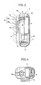
- Fig. 3 is a side view showing, in partial explosion, one embodiment of the portable power supply in accordance with the present invention;
- Fig. 4 is a bottom view showing, in partial explosion, one embodiment of the portable power supply in accordance with the present invention;
- Fig. 5 is cross sectional view taken along the line V-V of Fig. 2;
- Fig. 6 is a cross sectional view taken along the line VI-VI of Fig. 2;
- Fig. 7 is an electric circuit diagram of the portable power supply in accordance with the present invention;
- Fig. 8 shows the portable power supply of the present invention placed on the floor;
- Figs. 9A and 9B are partial perspective views showing another embodiment of heat radiating means in the portable power supply of the present invention;
- Fig. 10 is a partial cross sectional view showing a further embodiment of the heat radiating means in the portable power supply of the present invention;
- Fig. 11 is a cross sectional view showing another embodiment of the portable power supply of the present invention;
- Fig. 12 is a front view showing the portable power supply of the present invention when it falls;
- Fig. 13 is a schematic diagram showing one embodiment of noise preventing means provided on a cord connected to the output portion of the portable power supply of the present invention; and
- Fig. 14 is an electric circuit diagram showing the portable power supply when the noise preventing means of Fig. 13 is provided.
- An embodiment of the portable power supply in accordance with the present invention will be described in the following with reference to Figs. 1 to 4. The
portable power supply 1 comprises abody case 2. Thebody case 2 is a box-shaped case consisted of twohalves voltage lowering portion 4 consisted of a transformer or a transistor inverter are contained in thebody case 2. More specifically, fourstorage batteries 3, for instance, are contained along the center line N.A on one side in the longitudinal direction of the body case 2 (e.g. upper side when the case is attached to the human body by the attaching portion 13), and thevoltage lowering portion 4 is contained on the right side of the center line on the other (lower) side. Aninput portion 5 connected to a commercial power source is provided to be exposed on a prescribed surface, for example, lower end surface of thebody case 2. Anoutput portion 6 for supplying power charged in thestorage batteries 3 to a prescribed electronic device (not shown) is provided to be exposed on the upper end surface of thebody case 2. Aterminal pin 5a for coupling aplug 7 connected to an AC power supply through a connecting cord is provided at theinput portion 5. Theplug portion 8a is connected to theoutput portion 6 through the connectingcord 8. - Especially in this embodiment, the
input portion 5 is provided on the left side of the center line N.A on lower end surface of thebody case 2. Theoutput portion 6 is provided on the left side of the center line N.A on the upper end surface of thebody case 2. The relatively heavyvoltage lowering portion 4 is contained biased to the right side of the center line N.A in the lower portion of thebody case 2. A phantom line P connecting theinput portion 5 and theoutput portion 6 is positioned on the left side of the center line N.A. Therefore, the center of gravity G of thebody case 2 is biased the right side of the center line N.A. The center of gravity is further moved to the right when the body case is suspended by thecord 8. - The
body case 2 further contains acircuit board 10 including a charging circuit and the like. The body case is sealed by coupling thehalves coupling bolt 9. - Referring to Fig. 3, a hook shaped attaching
portion 13 is provided on the rear surface of thebody case 2. The hook shaped attachingportion 13 has abase end portion 13a provided projecting from thebody case 2 and an engagingportion 13b bent toward the side of the body with only the tip end portion thereof bent outward from the body. Thebase end portion 13a is mounted on a mountingportion 14 by thecoupling volt 9. The mountingportion 14 is a concave portion provided on the other end portion of thebody case 2.Ribs 13c for preventing slip are provided on the surface of the attachingportion 13b. The attachingportion 13 is formed of a flexible material such as synthetic resin or metal thin plate. There is a space t between the engagingportion 13b and the rear surface of thebody case 2. Namely, the attachingportion 13b is flexible to be bent to the side of thebody case 2, with thebase end portion 13a being the center. The attachingportion 13 is detachably attached to a waist A of a human body with the attachingportion 13 gripping a belt B. - A plurality of
concave grooves 15 are provided laterally on the surface of thebody case 2 which corresponds to the position of thestorage batteries 3 and of thevoltage lowering portion 4. Theconcave grooves 15 are provided for effectively radiating heat caused by the operation of thevoltage lowering portion 4 to the outside opposite to the waist A. By the provision of theseconcave grooves 15, the thickness of the wall portion of the half 2a on the surface side of thebody case 2 can be made thin, and the heat radiating area can be enlarged. Therefore, the heat radiating function of the surface side of thebody case 2 is significantly improved. For example, when the wall portion of thebody case 2 is formed of synthetic resin, the heat conductivity is inversely proportional to the thickness of the wall portion. Namely, the heat conductivity is doubled when the thickness of the wall portion is reduced to one half. In addition, by providing grooves having concave or arc cross section, the surface area of the wall portion is enlarged. The heat radiating effect of the surface of thebody case 2 can be further improved accordingly. - When the cross section of the groove is an arc, decrease of mechanical strength of the wall portion can be suppressed, compared with grooves having rectangular cross section, even when the thickness of the wall portion is reduced.
- As shown in Figs. 5 and 6, the
storage battery 3 and thevoltage lowering portion 4 are arranged in contact with the inner surface of the surface side of thehalf 2a. Therefore, decrease of strength of thehalf 2a caused by the formation of theconcave groove 15 is compensated for by thebattery 3 and thevoltage lowering portion 4, and at the same time, heat conductivity from thevoltage lowering portion 4 to thehalf 2a is improved. - Referring to Fig. 7, the
input portion 5 is connected to a primary side of thevoltage lowering portion 4 formed of a transformer or the like. The positive and negative output ends of a plurality ofstorage batteries 3 are connected to a secondary side of thevoltage lowering portion 4 through arectifier 16. Charging and power supply to electronic device can be simultaneously carried out by supplying power to theoutput portion 6 while the batteries are charged by the output from thevoltage lowering portion 4, in this manner. Further, the portable power supply can be used as an AC adapter by connecting theinput portion 5 to an AC power source and by connecting an electronic device to theoutput portion 6. - When this
power supply 1 is to be used as a backup power supply, thepower supply 1 is attached to one's body A by engaging the attachingportion 13 with a belt B. An electronic device is connected to theoutput portion 6 via theplug portion 8a, whereby power is supplied to the electronic device. When the output of thestorage battery 3 is reduced to be lower than a prescribed level as the batteries are discharged, thestorage batteries 3 are charged by connecting theplug 7 to theinput portion 5 and connecting a cord on the power source side to a commercial power source. In that case, as shown in Fig. 8, thepower supply 1 may be detached from the human body and placed on thefloor 20 or desk for charging. Now, when thebody case 2 is placed on the floor with the attachingportion 13 facing downward and the user happens to step on thebody case 2, an external force F directed downward is applied from above the surface. At that time, the attachingportion 13 is bent inward. However, since there is a space t, the external force F is absorbed by the elastic deformation of the attachingportion 13, and therefore, thepower supply 1 is not damaged. Even when an excessive external force F is applied and the space t cannot be ensured, the large external force F can be absorbed or released by deformation of the bent portion formed on the tip end of the attachingportion 13. in that case, the connectingcord 7 of the body case is held lift upward from the floor. Therefore, deformation of theinput portion 5 by the application of external force to the connecting cord can be prevented. - Let us consider a case in which the
power supply 1 is attached to a human body A for supplying power to an electronic device and for chargingstorage batteries 3 simultaneously. In that case, larger charging current flows in thevoltage lowering portion 4, compared with mere charging. Therefore, thevoltage lowering portion 4 is further heated. However, sinceconcave grooves 15 are formed on the surface of thebody case 2, the heat is emitted exclusively from the surface side having better heat radiation. Accordingly, heat is hardly transmitted to the human body through the rear surface of thebody case 2. Discomfort caused by the heat transmitted to the body can be prevented. - When the
power supply 1 is attached to a human body, thestorage batteries 3 are contained in the upper space of thebody case 2, and thevoltage lowering portion 4 is contained in the lower space of thebody case 2, so that a space is surely provided between the waist A and the lower portion of thebody case 2 where thevoltage lowering portion 4 is contained. By appropriately selecting such positional relation, the heat from thevoltage lowering portion 4 is hardly transmitted to the waist A. In addition, since thestorage batteries 3 are heavier than thevoltage lowering portion 4, the lower portion of thebody case 2 where thevoltage lowering portion 4 is positioned does not come closer to the waist A. Accordingly, thebody case 2 can be attached stably to the waist A of the human body by the attachingportion 13. - Various methods other than the above described embodiment may be used for improving heat radiation of the surface side of the
body case 2. For example, theconcave grooves 17 may be formed vertically as shown in Fig. 9A. By doing so, the heat tends to escape upward along the direction of the concave grooves. A plurality ofspots 18 may be provided as shown in Fig. 9B. The thickness D1 of the wall surface on the rear side of thebody case 2 may be made thicker and the thickness D2 of the wall surface of the surface side may be made thin. Alternatively, a heat radiating plate ormaterial 19 having high heat conductivity may be provided on the wall surface portion of thebody case 2 facing thevoltage lowering portion 4. Theheat radiating plate 19 is formed by mixing powder materials having high heat conductivity such as aluminum, copper, zinc or the like in a synthetic resin. - Fig. 11 is a cross sectional view showing another embodiment of the present invention. In this embodiment, positions of the
storage batteries 3 and thevoltage lowering portion 4 are selected to be inverted in the up and down directions. The attachingportion 13 is provided on the wall surface of the rear surface of thebody case 2 facing thevoltage lowering portion 4. At this time, a space T is surely provided between the waist A and thebody case 2, as the attachingportion 13 engaged with the belt B serves as a spacer. Therefore, even if the heat from thevoltage lowering portion 4 is transmitted to the rear surface of thebody case 2, the heat is emitted from the space T to the side, and the heat is hardly transmitted to the waist A. Thestorage batteries 3 heavier than thevoltage lowering portion 4 are positioned on the lower portion of thebody case 2. Therefore, even if the lower portion of thebody case 2 where thestorage batteries 3 are contained comes near to the waist A, the heat radiating path from thevoltage lowering portion 4 is not obstructed, and heat is not transmitted to the waist A. - The
portable power supply 1 may happen to fall when the attachingportion 13 is engaged with or detached from the belt B or when it is carried. However, the positional relation between respective portion is set such that the center of gravity G of thepower supply 1 is positioned on the right side (i.e. opposite to the position of formation of the output portion 5) of the center line N.A, as shown in Fig. 2. Therefore, if thepower supply 1 falls, thebody case 2 falls inclined to the side of the center of gravity G, as shown in Fig. 12. Accordingly, an end portion K opposite to theinput portion 5 first hits thefloor 20. Namely, theinput portion 5 provided on an end portion opposite to the end portion K can be prevented from first hitting the floor, whereby the damage to theinput portion 5 can be prevented. Even when thepower supply 1 falls with theoutput portion 6 facing downward, theoutput portion 6 can be protected from the shock of falling from the same reason. The input portion may be formed of a charging plug blade retractable from the side surface of thebody case 2. - When power supply is supplied to an electronic device including a high frequency clock source such as a microprocessor by using an external portable power supply through a connecting
code 8, other electronic devices may possibly be affected by unnecessary radiation generated at portions such as a connecting portion between the electronic device and the tipend plug portion 8a of the connectingcode 8 and from the connectingcode 8 itself. - In order to prevent this problem, noise preventing means may be provided at the connecting portion on the side of the electronic device. However, when the electronic device is operated by using the built-in power supply, the noise preventing means is unnecessary. In addition, provision of such a noise preventing means increases cost of the electronic device. Further, the provision of the noise preventing means increases the size of the electronic device, making it inconvenient to carry the electronic device.
- In view of the foregoing, in another preferred embodiment of the power supply of the present invention an
output plug portion 8a such as shown in Fig. 13 is employed. Noise preventing means is provided at theplug portion 8a. The connectingcode 8 is shielded. Tip ends of acore 81 and ashield 82 are wound four times over positions symmetrical to each other by the angle of 180° of theferrite core 83, respectively, and are connected to pinportions plug portion 8a. Theferrite core 83 is a ring formed of Ni-Zn material. Theplug portion 8a processed in this manner is covered by insert molding, using vinyl chloride resin. - Fig. 14 is an equivalent circuit diagram with the
plug portion 8a formed as shown in Fig. 13. In Fig. 14, the impedance on the side of thepin portions plug portion 8a in this manner, the electronic device can be made compact and handy. Even if the radiation frequency of the electronic device is different, only theplug portion 8a has to be changed to correspond thereto. - When the
ferrite core 83 is arranged in a direction orthogonal to the direction of attachment/detachment of theplug portion 8a, theferrite core 83 also serves as a reinforcement of the structure of theplug portion 8a. Accordingly, even when theplug portion 8a is coated and insert molded by a soft synthetic resin, it well withstands the force gripping theplug 8a when it is attached/detached. Accordingly, breaking between the core 81, theshield 82 and thepin portions - Although the present invention has been described and illustrated in detail, it is clearly understood that the same is by way of illustration and example only and is not to be taken by way of limitation, the spirit and scope of the present invention being limited only by the terms of the appended claims.
Claims (21)
a body case (2);
an attaching portion (13) for detachably attaching said body case (2) to a human body (A);
an input portion (5) provided exposed from said body case (2) and capable of being connected to a commercial power source through a connecting cord;
a voltage lowering portion (4) contained in said body case (2) for lowering voltage of power supplied from said input portion (5);
a storage battery (3) contained in said body case (2), charged by an output from said voltage lowering portion (4); and
an output portion (6) provided exposed from said body case (2) and capable of being connected to a prescribed electronic device through a connecting cord for supplying power charged in said storage battery (3) to the device.
said input portion (5) and said output portion (6) are selected to be positioned on one end and the other end portions opposing to each other of said body case (2).
said voltage lowering portion (4) is selected to be positioned on said one end portion of said body case (2), and said storage battery (3) is selected to be positioned on said the other end of said body case (2).
said attaching portion (13) is provided on one of major surfaces of said body case such that said one end portion is positioned lower side and said the other end portion is positioned upper side, when said body case (2) is attached to a human body (A).
a cord (8) connected to said output portion (6), the tip end of said cord (8) having a plug portion with noise preventing means (8a).
said body case (2) comprises opposing two major surfaces, said attaching portion (13) provided on one of said major surfaces.
said attaching portion (13) has a base portion (13a) provided projecting from one of said major surfaces, and an engaging portion (13b) provided continuous from the base portion (13a) bent to have a prescribed angle with the base portion (13a).
said engaging portion (13b) is provided to be spaced apart by a prescribed distance (t) from one of said major surfaces, and said attaching portion (13) is formed of a flexible material.
a body case (2) having opposing two major surfaces;
an attaching portion (13) provided on one of said major surfaces of said body case (2) for detachably attaching said body case (2) to a human body (A);
an input portion (5) provided exposed from said body case (2) to be connected to a commercial power source;
a voltage lowering portion (4) contained in said body case (2) for lowering voltage of power supplied from said input portion (5);
a storage battery (3) contained in said body case (2) charged by an output from said voltage lowering portion (4);
an output portion (6) provided exposed from said body case (2) connected for supplying power charged in said storage battery (3) to a prescribed electronic device; and
heat radiating means (15) formed on the other one of said major surfaces for making higher heat radiation of the other one of said major surfaces than said one of said major surfaces of said body case (2).
said heat radiating means comprises a concave portion formed on the other one of said major surfaces.
said concave portion is a plurality of grooves having concave cross section.
cross section of said groove having concave cross section is an arc cross section.
said plurality of grooves comprise grooves approximately parallel to each other.
said groove comprises a groove extending upward and downward, when said body case (2) is attached to a human body (A).
said storage battery (3) and said voltage lowering portion (4) are arranged in contact with the other one of said major surfaces in said body case (2).
the other one of said major surfaces with which at least said voltage lowering portion (4) is in contact is formed of a material having high heat conductivity.
the other one of said major surfaces has a portion thinner than said one of said major surfaces.
a body case (2) having two sections divided by a prescribed reference line (N.A);
an attaching portion (13) for detachably attaching said body case (2) to a human body (A);
an input portion (5) positioned in one of said sections of said body case (2), provided exposed from said body case (2) to be connected to a commercial power source;
a voltage lowering portion (4) contained at position biased to the side of the other section of said prescribed reference line in said body case (2) for lowering voltage of power supply from said input portion (5);
a storage battery (3) contained in said body case (2) to be charged by an output from said voltage lowering portion (4); and
an output portion (6) positioned in one of said sections of said body case (2), provided exposed from said body case (2) connected to supply power charged in said storage battery (3) to a prescribed electronic device; wherein
center of gravity of said portable power supply is positioned in the other one of said sections.
said input portion (5) is positioned on one end portion of said body case (2) in a direction of extension of said reference line (N.A), and said output portion (6) is positioned on the other end portion of said body case (2).
said input portion (5) and said output portion (6) are arranged such that a line (P) connecting said input portion (5) and said output portion (6) is approximately parallel to said reference line (N.A).
a body case (2) having opposing two major surfaces and two sections divided by a prescribed reference line (N.A);
an attaching portion (13) provided on one of said major surfaces of said body case (2) for detachably attaching said body case (2) to a human body (A);
an input portion (5) positioned in one of said sections of said body case (2), provided exposed from said body case (2) to be connected to a commercial power source;
a voltage lowering portion (4) contained at a position biased to the side of the other section of said prescribed reference line in said body case (2) for lowering voltage of power supplied from said input portion (5);
a storage battery (3) contained in said body case (2) charged by an output from said voltage lowering portion (4);
an output portion (6) positioned in one of said sections of said body case (2), provided exposed from said body case (2) connected for supplying power charged in said storage battery (3) to a prescribed electronic device; and
heat radiating means (15) formed on the other one of said major surfaces for making higher heat radiation of the other one of said major surfaces than said one of said major surfaces of said body case (2); wherein
center of gravity of said portable power supply is positioned in the other one of said sections.
Applications Claiming Priority (4)
| Application Number | Priority Date | Filing Date | Title |
|---|---|---|---|
| JP17744/89U | 1989-02-16 | ||
| JP1989017745U JPH083149Y2 (en) | 1989-02-16 | 1989-02-16 | Rechargeable power supply |
| JP17745/89U | 1989-02-16 | ||
| JP1989017744U JP2565359Y2 (en) | 1989-02-16 | 1989-02-16 | Portable power supply |
Publications (3)
| Publication Number | Publication Date |
|---|---|
| EP0383559A2 true EP0383559A2 (en) | 1990-08-22 |
| EP0383559A3 EP0383559A3 (en) | 1991-08-21 |
| EP0383559B1 EP0383559B1 (en) | 1995-01-25 |
Family
ID=26354303
Family Applications (1)
| Application Number | Title | Priority Date | Filing Date |
|---|---|---|---|
| EP90301544A Expired - Lifetime EP0383559B1 (en) | 1989-02-16 | 1990-02-14 | Portable power supply |
Country Status (5)
| Country | Link |
|---|---|
| US (1) | US5019767A (en) |
| EP (1) | EP0383559B1 (en) |
| CN (1) | CN2063715U (en) |
| CA (1) | CA2010066C (en) |
| DE (1) | DE69016221T2 (en) |
Cited By (5)
| Publication number | Priority date | Publication date | Assignee | Title |
|---|---|---|---|---|
| EP0433605A2 (en) * | 1989-11-20 | 1991-06-26 | Hagenuk Gmbh | Power supply, especially for telecommunication systems |
| WO1993007669A1 (en) * | 1991-10-08 | 1993-04-15 | Curtis Manufacturing Company, Inc. | Transformerless rechargeable battery power pack |
| WO1998016958A1 (en) * | 1996-10-15 | 1998-04-23 | Ericsson Inc. | Rechargeable battery enabling reduction of battery overheating probability during charging |
| EP1487080A1 (en) * | 2003-05-21 | 2004-12-15 | Kolvin Industries Ltd | Battery charger |
| CN109121440A (en) * | 2015-10-29 | 2019-01-01 | 株式会社Lg 化学 | The battery pack of lower case with small thickness and laptop computer including the battery pack |
Families Citing this family (95)
| Publication number | Priority date | Publication date | Assignee | Title |
|---|---|---|---|---|
| US5426347A (en) * | 1980-08-14 | 1995-06-20 | Nilssen; Ole K. | Lighting system with emergency standby feature |
| US5225762A (en) * | 1990-04-30 | 1993-07-06 | George Langford | Battery management system |
| SE466722B (en) * | 1990-07-31 | 1992-03-23 | Ericsson Telefon Ab L M | DRIVEN DRIVING A MOBILE PHONE |
| JPH04227170A (en) * | 1990-12-29 | 1992-08-17 | Sony Corp | Connector |
| US5177424A (en) * | 1991-09-20 | 1993-01-05 | Welch Allyn, Inc. | Instrument handle for use with interchangeable batteries |
| KR930011132B1 (en) * | 1991-11-01 | 1993-11-24 | 삼성전자 주식회사 | Control circuit of battery |
| US5260636A (en) * | 1991-11-18 | 1993-11-09 | Steven G. Leiserson | Plug-in rechargeable battery unit |
| JPH0779188A (en) * | 1993-06-30 | 1995-03-20 | Uniden Corp | Power supply changeover circuit |
| FR2721766B1 (en) * | 1994-06-28 | 1996-07-26 | Thomson Consumer Electronics | Electronic device with two power modes. |
| US5565756A (en) * | 1994-07-11 | 1996-10-15 | Motorola, Inc. | Microprocessor controlled portable battery charger and method of charging using same |
| US5554896A (en) * | 1994-10-28 | 1996-09-10 | Miyad | Portable power supply for handpieces |
| USD383115S (en) * | 1995-09-26 | 1997-09-02 | Motorola, Inc. | Power adapter |
| US6041242A (en) * | 1996-06-21 | 2000-03-21 | Coulthard; Steve M. | Portable emergency response communications system and method |
| US5929597A (en) * | 1997-04-23 | 1999-07-27 | Fiskars Inc. | Portable electrical power system to supply direct current voltage |
| JP3767977B2 (en) * | 1997-06-24 | 2006-04-19 | 三洋電機株式会社 | Pack battery |
| DE19913077C2 (en) * | 1999-03-23 | 2003-06-12 | Wacker Construction Equipment | Internal vibrator with measuring system |
| JP2001268812A (en) * | 2000-03-23 | 2001-09-28 | Sanyo Electric Co Ltd | Portable electric equipment with built-in battery |
| US6445086B1 (en) * | 2000-06-28 | 2002-09-03 | David H. Houston | Electronic power supply for personal computer and method |
| DE10033137A1 (en) | 2000-07-07 | 2002-01-31 | Wacker Werke Kg | Frequency converter for an internal vibrator |
| US6596941B2 (en) * | 2001-06-13 | 2003-07-22 | Salvatore M. Tripoli | A.C. electrical power delivery system for a pickup truck bed utility box |
| DE20110841U1 (en) * | 2001-06-30 | 2001-09-20 | Dewert Antriebs Systemtech | Electromotive actuator |
| JP3690665B2 (en) * | 2001-10-30 | 2005-08-31 | インターナショナル・ビジネス・マシーンズ・コーポレーション | ELECTRIC DEVICE, COMPUTER DEVICE, AND POWER SUPPLY METHOD |
| US6939641B2 (en) * | 2002-12-20 | 2005-09-06 | Motorola, Inc. | Detached portable battery with universal clip |
| TWM271305U (en) * | 2004-09-27 | 2005-07-21 | L & K Precision Tech Co Ltd | Charger |
| JP2007014137A (en) * | 2005-06-30 | 2007-01-18 | Mitsumi Electric Co Ltd | Ac adapter |
| US20080063936A1 (en) * | 2006-09-11 | 2008-03-13 | Hansen Leroy C | Portable Battery Power Supply |
| US7515423B2 (en) * | 2006-09-22 | 2009-04-07 | Fu Zhun Precision Industry (Shen Zhen) Co., Ltd. | Heat dissipation device |
| TW200820885A (en) * | 2006-10-31 | 2008-05-01 | Delta Electronics Inc | Passive heat-dissipating type power supply capable of increasing heat-dissipating efficiency and manufacturing method thereof |
| US8441216B2 (en) | 2008-09-03 | 2013-05-14 | ALVA Systems, Inc. | Power supply system for a building |
| US8198757B2 (en) * | 2009-03-04 | 2012-06-12 | International Business Machines Corporation | Energy savings for a system powering a lower voltage device from a higher voltage power source, and wherein the system includes a power plug that outputs power to a converter, and a switch actuator |
| US20150212544A1 (en) * | 2010-03-19 | 2015-07-30 | Shih-Hui Chen | Mounting Apparatus For Auxiliary Device |
| US8741403B2 (en) * | 2010-03-19 | 2014-06-03 | Tennrich International Corp. | Flexible disposition apparatus |
| US20120126621A1 (en) | 2010-11-10 | 2012-05-24 | Michael Scott Brownlee | Lighting system |
| US9174691B2 (en) * | 2011-07-21 | 2015-11-03 | Dan Goldwater | Universal mount battery holder for bicycles |
| USD667788S1 (en) * | 2011-09-28 | 2012-09-25 | Huabin Mai | Portable power supply |
| US20130343042A1 (en) * | 2012-06-21 | 2013-12-26 | Coast Cutlery Company | Rechargeable flashlight |
| TWD163147S (en) * | 2013-06-08 | 2014-09-21 | 台達電子企業管理(上海) | Adapter |
| USD750563S1 (en) * | 2013-11-04 | 2016-03-01 | Savant Systems, Llc | Lamp module for a lighting control system |
| US9780344B2 (en) * | 2014-10-22 | 2017-10-03 | Lat Enterprises | Portable battery pack comprising a battery enclosed by a wearable and replaceable pouch or skin |
| TWI474769B (en) * | 2014-03-04 | 2015-02-21 | Cheng Uei Prec Ind Co Ltd | Power device and assembling method thereof |
| USD743335S1 (en) * | 2014-04-04 | 2015-11-17 | Kupa Inc | Portable power supply |
| USD742819S1 (en) * | 2014-05-22 | 2015-11-10 | Samsung Electronics Co., Ltd. | Battery charger |
| USD744943S1 (en) * | 2014-06-24 | 2015-12-08 | Deltona Transformer Corporation | Battery charger |
| USD744942S1 (en) * | 2014-06-24 | 2015-12-08 | Deltona Transformer Corporation | Battery charger |
| USD745455S1 (en) * | 2014-07-16 | 2015-12-15 | The Noco Company | Battery booster |
| USD746770S1 (en) * | 2014-07-16 | 2016-01-05 | The Noco Company | Battery booster |
| USD760164S1 (en) * | 2014-08-05 | 2016-06-28 | Garrett Aida | Portable power supply |
| USD806026S1 (en) * | 2015-04-24 | 2017-12-26 | Das Companies, Inc. | Power inverter |
| USD788032S1 (en) * | 2015-09-16 | 2017-05-30 | Ningbo Geostar Phtoelectric Technology Co., Ltd. | Charger |
| JP1547883S (en) * | 2015-09-29 | 2016-04-18 | ||
| USD780727S1 (en) * | 2015-12-04 | 2017-03-07 | Howard Wang | Wireless adapter |
| USD766827S1 (en) * | 2015-12-11 | 2016-09-20 | Yutou Technology (Hangzhou) Co., Ltd. | Power adapter for a robot |
| USD793955S1 (en) * | 2016-04-29 | 2017-08-08 | Ningbo Gude Electronic Technology Co., Ltd. | Inverter battery charger |
| USD823790S1 (en) * | 2016-07-14 | 2018-07-24 | OjO Electric LLC | Charger |
| USD811363S1 (en) * | 2016-07-21 | 2018-02-27 | HuNan Jianghan Electronics Technology Co., Ltd | Lightning port earphones |
| USD851033S1 (en) * | 2016-12-12 | 2019-06-11 | Fortune Fountains (Asia) Limited | Mobile power bank |
| USD836067S1 (en) * | 2016-12-14 | 2018-12-18 | Black & Decker Inc. | Battery charger |
| USD815070S1 (en) * | 2016-12-29 | 2018-04-10 | Facebook, Inc. | Electronic device |
| USD841619S1 (en) * | 2017-03-24 | 2019-02-26 | Klein Electronics, Inc. | Two-way radio headset with boom microphone |
| USD842839S1 (en) * | 2017-03-24 | 2019-03-12 | Klein Electronics, Inc. | Dual ear piece mobile phone headset with boom microphone |
| USD817873S1 (en) * | 2017-03-30 | 2018-05-15 | Mathew Inskeep | Battery charger |
| USD815035S1 (en) * | 2017-05-12 | 2018-04-10 | Guangdong Bestek E-Commerce Co., Ltd. | Charger |
| USD934807S1 (en) * | 2017-09-28 | 2021-11-02 | Crestron Electronics, Inc. | Multiple connector device |
| USD840927S1 (en) * | 2017-12-07 | 2019-02-19 | Mathew Inskeep | Battery charger |
| USD867985S1 (en) | 2017-12-21 | 2019-11-26 | The Noco Company | Combination jump starter and display |
| USD845892S1 (en) * | 2018-01-08 | 2019-04-16 | Ling To Shum | Battery charger |
| USD890099S1 (en) | 2018-05-16 | 2020-07-14 | Klein Electronics, Inc. | Ruggedized side connector for audio accessories |
| USD913935S1 (en) | 2018-10-01 | 2021-03-23 | The Noco Company | Battery clamp |
| USD913937S1 (en) | 2018-10-03 | 2021-03-23 | The Noco Company | Battery clamp |
| USD997102S1 (en) | 2018-10-03 | 2023-08-29 | The Noco Company | Battery clamp |
| USD913938S1 (en) | 2018-10-03 | 2021-03-23 | The Noco Company | Battery clamp |
| USD975645S1 (en) | 2018-12-04 | 2023-01-17 | Klein Electronics, Inc. | Secure audio accessory connector |
| USD928740S1 (en) | 2019-08-30 | 2021-08-24 | Klein Electronics, Inc. | Touchscreen push-to-talk button |
| USD919572S1 (en) * | 2020-01-15 | 2021-05-18 | Shenzhen Carku Technology Co., Limited | Starting power supply |
| USD910552S1 (en) * | 2020-03-10 | 2021-02-16 | Shenzhen Jiuniuhai Technology Co., Ltd. | Battery charger |
| USD913227S1 (en) * | 2020-03-18 | 2021-03-16 | Shenzhen City JinMeiLun Business trade Co., Ltd | Battery converter |
| USD981334S1 (en) | 2020-11-19 | 2023-03-21 | The Noco Company | Jump starter |
| USD981333S1 (en) | 2020-11-19 | 2023-03-21 | The Noco Company | Jump starter |
| USD993910S1 (en) | 2020-11-25 | 2023-08-01 | The Noco Company | Battery charging device |
| USD981335S1 (en) | 2020-11-25 | 2023-03-21 | The Noco Company | Jump starter |
| USD981953S1 (en) | 2020-11-25 | 2023-03-28 | The Noco Company | Jump starting device |
| USD984381S1 (en) | 2020-11-25 | 2023-04-25 | The Noco Company | Battery cable assembly for jump starting device |
| USD993911S1 (en) | 2020-11-25 | 2023-08-01 | The Noco Company | Battery charging device |
| USD991162S1 (en) | 2020-12-07 | 2023-07-04 | The Noco Company | Battery charger |
| USD1003237S1 (en) | 2020-12-07 | 2023-10-31 | The Noco Company | Battery charger |
| USD981336S1 (en) | 2020-12-07 | 2023-03-21 | The Noco Company | Battery charger |
| USD988988S1 (en) | 2020-12-11 | 2023-06-13 | The Noco Company | Battery charger |
| USD991185S1 (en) | 2020-12-11 | 2023-07-04 | The Noco Company | Battery cable assembly |
| USD988990S1 (en) | 2020-12-11 | 2023-06-13 | The Noco Company | Battery charger |
| USD991186S1 (en) | 2020-12-11 | 2023-07-04 | The Noco Company | Battery cable assembly |
| USD981337S1 (en) | 2020-12-11 | 2023-03-21 | The Noco Company | Battery charger |
| USD988989S1 (en) | 2020-12-11 | 2023-06-13 | The Noco Company | Battery charger |
| USD988257S1 (en) | 2020-12-11 | 2023-06-06 | The Noco Company | Battery charger |
| US11639789B2 (en) | 2021-01-13 | 2023-05-02 | Streamlight, Inc. | Portable light and keyed rechargeable USB battery |
| USD1014424S1 (en) * | 2021-08-27 | 2024-02-13 | Fk Irons Inc. | Power supply |
Citations (5)
| Publication number | Priority date | Publication date | Assignee | Title |
|---|---|---|---|---|
| US3274476A (en) * | 1963-10-30 | 1966-09-20 | Wildum Paul | Article carrying belt |
| US3919615A (en) * | 1974-03-18 | 1975-11-11 | Ronald Niecke | Power belt |
| JPS57161768U (en) * | 1981-04-02 | 1982-10-12 | ||
| JPS60855U (en) * | 1983-06-21 | 1985-01-07 | ソニー株式会社 | battery case |
| US4748344A (en) * | 1987-03-23 | 1988-05-31 | Peter Sing | Portable power supply carrier |
Family Cites Families (4)
| Publication number | Priority date | Publication date | Assignee | Title |
|---|---|---|---|---|
| JPS602026B2 (en) * | 1979-10-23 | 1985-01-18 | 寶酒造株式会社 | Mirin manufacturing method |
| JPS56166664A (en) * | 1980-05-28 | 1981-12-21 | Canon Inc | Facsimile equipment |
| US4382220A (en) * | 1981-07-20 | 1983-05-03 | The Bridgeport Metal Goods Mfg. Co. | Rechargeable battery pack and combination thereof with lantern |
| GB8619187D0 (en) * | 1986-08-06 | 1986-09-17 | Control Systems Ltd | Ticket issuing machines |
-
1990
- 1990-02-12 US US07/479,149 patent/US5019767A/en not_active Expired - Lifetime
- 1990-02-14 EP EP90301544A patent/EP0383559B1/en not_active Expired - Lifetime
- 1990-02-14 DE DE69016221T patent/DE69016221T2/en not_active Expired - Lifetime
- 1990-02-14 CA CA002010066A patent/CA2010066C/en not_active Expired - Lifetime
- 1990-02-16 CN CN90201803U patent/CN2063715U/en not_active Expired - Lifetime
Patent Citations (5)
| Publication number | Priority date | Publication date | Assignee | Title |
|---|---|---|---|---|
| US3274476A (en) * | 1963-10-30 | 1966-09-20 | Wildum Paul | Article carrying belt |
| US3919615A (en) * | 1974-03-18 | 1975-11-11 | Ronald Niecke | Power belt |
| JPS57161768U (en) * | 1981-04-02 | 1982-10-12 | ||
| JPS60855U (en) * | 1983-06-21 | 1985-01-07 | ソニー株式会社 | battery case |
| US4748344A (en) * | 1987-03-23 | 1988-05-31 | Peter Sing | Portable power supply carrier |
Cited By (8)
| Publication number | Priority date | Publication date | Assignee | Title |
|---|---|---|---|---|
| EP0433605A2 (en) * | 1989-11-20 | 1991-06-26 | Hagenuk Gmbh | Power supply, especially for telecommunication systems |
| EP0433605A3 (en) * | 1989-11-20 | 1992-11-04 | Hagenuk Gmbh | Power supply, especially for telecommunication systems |
| WO1993007669A1 (en) * | 1991-10-08 | 1993-04-15 | Curtis Manufacturing Company, Inc. | Transformerless rechargeable battery power pack |
| WO1998016958A1 (en) * | 1996-10-15 | 1998-04-23 | Ericsson Inc. | Rechargeable battery enabling reduction of battery overheating probability during charging |
| US5918186A (en) * | 1996-10-15 | 1999-06-29 | Ericsson Inc. | Rechargeable battery enabling reduction of battery overheating probability during charging |
| EP1487080A1 (en) * | 2003-05-21 | 2004-12-15 | Kolvin Industries Ltd | Battery charger |
| US6956354B2 (en) | 2003-05-21 | 2005-10-18 | Kolvin Industries Ltd. | Battery charger |
| CN109121440A (en) * | 2015-10-29 | 2019-01-01 | 株式会社Lg 化学 | The battery pack of lower case with small thickness and laptop computer including the battery pack |
Also Published As
| Publication number | Publication date |
|---|---|
| CN2063715U (en) | 1990-10-10 |
| EP0383559B1 (en) | 1995-01-25 |
| DE69016221D1 (en) | 1995-03-09 |
| EP0383559A3 (en) | 1991-08-21 |
| DE69016221T2 (en) | 1995-07-27 |
| CA2010066C (en) | 1996-01-02 |
| CA2010066A1 (en) | 1990-08-16 |
| US5019767A (en) | 1991-05-28 |
Similar Documents
| Publication | Publication Date | Title |
|---|---|---|
| US5019767A (en) | Portable power supply | |
| US4998055A (en) | Externally rechargeable battery pack for a computer | |
| US8026693B2 (en) | Induction charger for portable battery-powered devices | |
| JP5563501B2 (en) | Non-contact charging battery pack and control method thereof | |
| US5162719A (en) | Battery pack charger | |
| CA2070493C (en) | Call selective receiver built in with vibrator | |
| EP0572189B1 (en) | Battery charging equipment for a cordless telephone | |
| US5046131A (en) | Portable radio transceiver apparatus | |
| US10547036B1 (en) | Power interface ensemble and module for mobile consumer electronics | |
| US20030121682A1 (en) | Independent electrical implement system | |
| CN215870862U (en) | Outdoor solar mobile energy storage power supply | |
| KR970001229Y1 (en) | Portable power supply | |
| CN210201844U (en) | Portable handheld shielding device | |
| CN206117256U (en) | Charging device with battery charging outfit bracket | |
| JPH083149Y2 (en) | Rechargeable power supply | |
| JP2560078B2 (en) | DC connection box | |
| CN215870858U (en) | Portable mobile energy storage power supply | |
| WO1992008293A1 (en) | Carry case assembly for a portable electrical device | |
| CN215499522U (en) | Wireless charging earphone | |
| JP3391983B2 (en) | Rechargeable electrical equipment | |
| CN216929634U (en) | Energy storage power supply | |
| KR200212929Y1 (en) | Belt-shaped battery | |
| CN211127190U (en) | Circular large-screen power bank | |
| CN216672639U (en) | Portable power source capable of being carried at any time | |
| CN215646239U (en) | Wireless charging device of multipurpose |
Legal Events
| Date | Code | Title | Description |
|---|---|---|---|
| PUAI | Public reference made under article 153(3) epc to a published international application that has entered the european phase |
Free format text: ORIGINAL CODE: 0009012 |
|
| AK | Designated contracting states |
Kind code of ref document: A2 Designated state(s): DE FR GB SE |
|
| 17P | Request for examination filed |
Effective date: 19901219 |
|
| PUAL | Search report despatched |
Free format text: ORIGINAL CODE: 0009013 |
|
| AK | Designated contracting states |
Kind code of ref document: A3 Designated state(s): DE FR GB SE |
|
| 17Q | First examination report despatched |
Effective date: 19930907 |
|
| GRAA | (expected) grant |
Free format text: ORIGINAL CODE: 0009210 |
|
| AK | Designated contracting states |
Kind code of ref document: B1 Designated state(s): DE FR GB SE |
|
| REF | Corresponds to: |
Ref document number: 69016221 Country of ref document: DE Date of ref document: 19950309 |
|
| ET | Fr: translation filed | ||
| PLBE | No opposition filed within time limit |
Free format text: ORIGINAL CODE: 0009261 |
|
| STAA | Information on the status of an ep patent application or granted ep patent |
Free format text: STATUS: NO OPPOSITION FILED WITHIN TIME LIMIT |
|
| 26N | No opposition filed | ||
| REG | Reference to a national code |
Ref country code: GB Ref legal event code: IF02 |
|
| PGFP | Annual fee paid to national office [announced via postgrant information from national office to epo] |
Ref country code: DE Payment date: 20090213 Year of fee payment: 20 |
|
| PGFP | Annual fee paid to national office [announced via postgrant information from national office to epo] |
Ref country code: GB Payment date: 20090211 Year of fee payment: 20 |
|
| PGFP | Annual fee paid to national office [announced via postgrant information from national office to epo] |
Ref country code: SE Payment date: 20090206 Year of fee payment: 20 |
|
| PGFP | Annual fee paid to national office [announced via postgrant information from national office to epo] |
Ref country code: FR Payment date: 20090213 Year of fee payment: 20 |
|
| REG | Reference to a national code |
Ref country code: GB Ref legal event code: PE20 Expiry date: 20100213 |
|
| PG25 | Lapsed in a contracting state [announced via postgrant information from national office to epo] |
Ref country code: GB Free format text: LAPSE BECAUSE OF EXPIRATION OF PROTECTION Effective date: 20100213 |
|
| PG25 | Lapsed in a contracting state [announced via postgrant information from national office to epo] |
Ref country code: DE Free format text: LAPSE BECAUSE OF EXPIRATION OF PROTECTION Effective date: 20100214 |