EP0388839A2 - Remote meter configuration - Google Patents
Remote meter configuration Download PDFInfo
- Publication number
- EP0388839A2 EP0388839A2 EP90105117A EP90105117A EP0388839A2 EP 0388839 A2 EP0388839 A2 EP 0388839A2 EP 90105117 A EP90105117 A EP 90105117A EP 90105117 A EP90105117 A EP 90105117A EP 0388839 A2 EP0388839 A2 EP 0388839A2
- Authority
- EP
- European Patent Office
- Prior art keywords
- meter
- code
- register
- configuration
- new
- Prior art date
- Legal status (The legal status is an assumption and is not a legal conclusion. Google has not performed a legal analysis and makes no representation as to the accuracy of the status listed.)
- Granted
Links
Images


Classifications
-
- G—PHYSICS
- G07—CHECKING-DEVICES
- G07F—COIN-FREED OR LIKE APPARATUS
- G07F7/00—Mechanisms actuated by objects other than coins to free or to actuate vending, hiring, coin or paper currency dispensing or refunding apparatus
- G07F7/08—Mechanisms actuated by objects other than coins to free or to actuate vending, hiring, coin or paper currency dispensing or refunding apparatus by coded identity card or credit card or other personal identification means
- G07F7/10—Mechanisms actuated by objects other than coins to free or to actuate vending, hiring, coin or paper currency dispensing or refunding apparatus by coded identity card or credit card or other personal identification means together with a coded signal, e.g. in the form of personal identification information, like personal identification number [PIN] or biometric data
- G07F7/1016—Devices or methods for securing the PIN and other transaction-data, e.g. by encryption
-
- G—PHYSICS
- G07—CHECKING-DEVICES
- G07B—TICKET-ISSUING APPARATUS; FARE-REGISTERING APPARATUS; FRANKING APPARATUS
- G07B17/00—Franking apparatus
- G07B17/00016—Relations between apparatus, e.g. franking machine at customer or apparatus at post office, in a franking system
- G07B17/0008—Communication details outside or between apparatus
-
- G—PHYSICS
- G07—CHECKING-DEVICES
- G07B—TICKET-ISSUING APPARATUS; FARE-REGISTERING APPARATUS; FRANKING APPARATUS
- G07B17/00—Franking apparatus
- G07B17/00733—Cryptography or similar special procedures in a franking system
-
- G—PHYSICS
- G07—CHECKING-DEVICES
- G07B—TICKET-ISSUING APPARATUS; FARE-REGISTERING APPARATUS; FRANKING APPARATUS
- G07B17/00—Franking apparatus
- G07B17/00016—Relations between apparatus, e.g. franking machine at customer or apparatus at post office, in a franking system
- G07B17/0008—Communication details outside or between apparatus
- G07B2017/00153—Communication details outside or between apparatus for sending information
- G07B2017/00161—Communication details outside or between apparatus for sending information from a central, non-user location, e.g. for updating rates or software, or for refilling funds
-
- G—PHYSICS
- G07—CHECKING-DEVICES
- G07B—TICKET-ISSUING APPARATUS; FARE-REGISTERING APPARATUS; FRANKING APPARATUS
- G07B17/00—Franking apparatus
- G07B17/00016—Relations between apparatus, e.g. franking machine at customer or apparatus at post office, in a franking system
- G07B17/0008—Communication details outside or between apparatus
- G07B2017/00153—Communication details outside or between apparatus for sending information
- G07B2017/00169—Communication details outside or between apparatus for sending information from a franking apparatus, e.g. for verifying accounting
-
- G—PHYSICS
- G07—CHECKING-DEVICES
- G07B—TICKET-ISSUING APPARATUS; FARE-REGISTERING APPARATUS; FRANKING APPARATUS
- G07B17/00—Franking apparatus
- G07B17/00185—Details internally of apparatus in a franking system, e.g. franking machine at customer or apparatus at post office
- G07B17/00362—Calculation or computing within apparatus, e.g. calculation of postage value
- G07B2017/00419—Software organization, e.g. separation into objects
-
- G—PHYSICS
- G07—CHECKING-DEVICES
- G07B—TICKET-ISSUING APPARATUS; FARE-REGISTERING APPARATUS; FRANKING APPARATUS
- G07B17/00—Franking apparatus
- G07B17/00733—Cryptography or similar special procedures in a franking system
- G07B2017/00822—Cryptography or similar special procedures in a franking system including unique details
- G07B2017/0083—Postal data, e.g. postage, address, sender, machine ID, vendor
-
- G—PHYSICS
- G07—CHECKING-DEVICES
- G07B—TICKET-ISSUING APPARATUS; FARE-REGISTERING APPARATUS; FRANKING APPARATUS
- G07B17/00—Franking apparatus
- G07B17/00733—Cryptography or similar special procedures in a franking system
- G07B2017/00935—Passwords
Definitions
- the present invention relates generally to postage meters and more particularly to electronic meters capable of being reconfigured.
- a customer needing to replace the meter or wanting to change the features on his meter must wait for the agent of the meter company to obtain a meter having the desired set of features. If the agent does not have a large inventory, it becomes necessary to have a meter configured at the factory. Therefore, any attempts to reduce the number of meters in the pipeline will adversely affect the length of time necessary to service the customer's request.
- the present invention provides a technique for securely reconfiguring postage meters in the field, thereby allowing variation of the features of the meter.
- the technique is readily implemented in the meter software. Because the technique provides security over the meter reconfiguration process, only authorized meter reconfigurations can occur. Therefore, the company will always have a correct record of the configuration of the meter in the field.
- the technique assumes that the meter has a set of features that may be selectively enabled or disabled by software.
- the meter is capable of being put into a configuration mode by suitable entries from the keyboard, in which mode it is inhibited from printing postage.
- the meter has a storage register for a current or old meter type, and can receive a desired new meter type via keyboard entry.
- the meter has software for generating an encrypted configuration request code that is partially based on the values of the old and new meter types.
- the configuration request code when communicated to a data center computer along with other validating identification information, is checked by the data center computer which computes the configuration request code using the same algorithm. If the two values agree, the data center computer generates an encrypted configuration enable code that is partially based on the meter serial number.
- the meter which receives the meter generated configuration enable code and also generates an internal configuration enable code using the same algorithm as the data center computer. If the configuration enable codes agree, the meter overwrites the old meter type number with the new meter type number, thereby reconfiguring the meter.
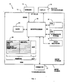
- Fig. 1 is a block diagram of a preferred postage meter 10 that can be reconfigured in the field.
- Meter 10 includes a print mechanism 12, accounting registers, and control electronics, all enclosed within a secure meter housing 13.
- a keyboard 14 and a display 16 provide the user interface.
- a connector 17 provides an electrical connection with a mailing machine for control of the printing process.
- the control electronics includes a digital microprocessor 18 which controls the operation of the meter, including the basic functions of printing and accounting for postage, and optional features such as department accounting and remote setting.
- the microprocessor is connected to a clock 20, a read only memory (ROM) 22, a random access memory (RAM) 24, and a battery augmented memory (BAM) 26.
- ROM read only memory
- RAM random access memory
- BAM battery augmented memory
- ROM 22 is primarily used for storing nonvolatile information such as software and data/function tables necessary to run the microprocessor. The ROM can only be changed at the factory.
- RAM 24 is used for intermediate storage of variables and other data during meter operation.
- BAM 26 is primarily used to store accounting information that must be kept when the meter is powered down. The BAM is also used for storing certain flags and other information that is necessary to the functioning of the microprocessor. Such information includes meter identifying data such as the meter serial number and BAM initialization date, and a number of parameters relevant to the remote configuration of the meter.
- the meter is provided with a number of features that may be enabled or disabled by software. Representative features include department accounting (with various levels of sophistication and numbers of departments that can be tracked), set date prompt, low postage warning, calculator mode variable length security codes (see Appendix D for details), and remote setting.
- the remote setting feature is a capability of having the meter's postage amount increased without removing the meter from the customer site.
- the meter postage amount can be increased by a variable amount during the remote setting process.
- the meter postage amount can be increased by a fixed increment called the fixed remote setting amount.
- the fixed remote setting amount may then be varied during remote configuration of the meter.
- the meter may have four print wheels (maximum postage $99.99), but the high order print wheel may be disabled (maximum postage $9.99).
- certain meter features are hardware configured and cannot be set by software. This includes the print indicium (U.S. Postal Service or United Parcel Service) and the position of the decimal point (four-bank whole cents or four-bank decimal cents). These features may be software controlled and configurable in alternative embodiments of the invention.
- MTN meter type number
- the microprocessor performs several initialization procedures during meter power-up.
- the microprocessor uses the MTN stored in BAM to index in RAM the software code stored in ROM to tables also stored in ROM. This indexing allows the microprocessor to more quickly read the proper tables for information without having to repeatedly determine what table to read.
- One indexed table is a Meter Selection Table which contains information regarding what features the meter has based upon the MTN and the type of meter (i.e. U.S. Postal Service or United Parcel Service, four-bank whole cents or four-bank decimal cents, etc.).
- Another indexed table is a Key Table which contains the address of the appropriate software code to be executed when a key is pressed by the user. The Key Table indexing is also partially based upon the MTN. After the initialization procedures are performed, the microprocessor waits for user input.
- the microprocessor is able to determine user input by periodically scanning the keyboard. As a key is pressed, x and y coordinate values are determined by the microprocessor. The microprocessor converts the x and y coordinate values to an equivalent ASCII byte. The microprocessor sends the ASCII byte to the display, which contains its own internal decoder and driver for displaying the ASCII information to the user. The microprocessor then determines what software code in ROM to execute based upon the ASCII byte by reading the indexed Key Table in ROM.
- the software code contains branch points where the microprocessor must read a table in ROM or a variable in BAM to determine which code to execute.
- the microprocessor may read the indexed Meter Selection Table to determine whether the meter is configured to have a certain feature or not and thereby execute the appropriate code.
- the microprocessor Upon the execution of the appropriate software code, the microprocessor returns to a scanning state as it waits for further user input.
- the meter is configured to a standard feature set before leaving the factory. Because the feature set is known, the meter can be functional and still does not need to be registered on the data center computer until it has been reconfigured a first time. In an alternative embodiments, the meter can be disabled state for security reasons until it has been reconfigured a first time.
- the meter's serial number, present configuration and other information specific to the meter (which were already stored in the meter's memory during an initialization process at the factory) are entered on the data center computer.
- the meter and the computer are then able to generate identical encrypted codes by using the same encryption routine and input numbers.
- the encrypted codes help the data center computer maintain control over the feature set of each meter.
- CTID configuration transaction identifier
- STID setting transaction identifier
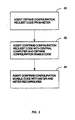
- Fig. 2 is a high level flowchart of the process necessary for reconfiguring the postage meter by an agent at a customer's site or at the agent's technical service area.
- the agent obtains a configuration request code generated by the meter.
- This configuration request code is essentially a password to the data center computer, and is based upon a combination of factors, the combination of which only the data center computer would know.
- the agent confirms the configuration request code with the data center computer. Upon confirmation from the computer, the computer provides a configuration enable code back to the agent.
- the configuration enable code is essentially a password from the data center computer to the meter stating that it is permissible to reconfigure to the desired feature set.
- the agent enters the configuration enable code into the meter. The meter confirms the configuration enable code and reconfigures itself.
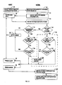
- Fig. 3 is a detailed flowchart of stage 30 for the first and second embodiments.
- Some meters have displays that are sophisticated and allow for user prompting. Therefore, in each of the steps described below where the meter requires certain information in order to move to the next step, some meters may prompt the agent to make that step.
- a first step 40 the agent then puts the meter into a remote configuration mode by pressing a certain key sequence and entering a service access code.
- the key sequence is not obvious. This prevents customers and other unauthorized personnel from accidentally entering the configuration mode.
- the service access code is known to the agent and must be entered after completing the key sequence within a limited time interval that is checked by the microprocessor in combination with the clock. This further prevents customers and other unauthorized personnel from entering the configuration mode.
- the meter Upon entry of the predetermined key sequence and the agent access code, the meter enters the remote configuration mode by setting a mode register located in BAM (step 42). This prevents the meter from being used for printing purposes while being reconfigured.
- the meter then displays the meter serial number, the meter BAM initialization date, and the old meter type number (old MTN).
- the BAM initialization date is preferably a four digit number wherein the four digits YDDD express the date in which the meter was last initialized.
- the DDD stands for the number of days since December 31 and Y is the least significant digit of the year in which the meter was initialized.
- the old MTN is a number that defines the present feature set that the meter is presently configured to.
- the meter displays the above numbers and the Ascending Register amount or some other meter specific identifying information.
- the Ascending Register contains the amount of postage the meter has printed since the meter has been initialized.
- the agent then enters the new MTN into the meter (step 46).
- This new number represents the set of features that the meter will have after reconfiguration.
- the agent must then press a selected key, such as the ENTER key, followed by the service access code within a limited time interval to indicate that the entered new MTN is correct and desired. If the entered new MTN is incorrect or not desired, the agent may let the timer expire or press another selected key such as a CLEAR key.
- the agent then enters the correct new MTN or exits the remote configuration mode. Once the correct new MTN is entered, the agent must press the selected key (i.e., ENTER) followed by the service access code within a limited time interval to indicate that it is the correct new MTN.
- the meter then stores the new MTN in BAM (step 48).
- the meter then performs a series of tests to determine whether the meter is authorized to reconfigure to the new feature set represented by the new MTN.
- the meter also allows the agent to enter the fixed remote setting amount following the series of tests.
- the first embodiment performs steps 50-54 while the second embodiment performs steps 50-58. That is, the second embodiment performs the steps contained within the dotted box 55 in addition to steps 50-54.
- the remote setting feature is being enabled or disabled (step 50), and if the Descending Register (which contains the amount of postage the meter is authorized to print) is greater than zero (step 51), then the new MTN is not accepted.
- the agent is notified (step 52) and the agent is able to enter a new MTN (step 46). If the meter Descending Register amount is equal to zero (step 51), the new MTN disables remote setting (step 53), and the meter installation flag is set, then the meter will not accept the new MTN for security reasons. As before, the agent is notified (step 52) and the agent is able to enter a new MTN (step 46).
- step 50 if the results of step 50 is no (or false) or if the result of step 53 is yes (or true), then the steps in dotted box 55 are not performed.
- the agent enters the fixed remote setting amount. Furthermore, if the results of step 53 is yes (or true), then the agent enters the fixed remote setting amount.
- the meter then prompts the agent for confirmation of the new MTN. If the agent wants to start the process again with a new MTN, then the agent must press a selected key such as the CLEAR key (step 62). If the agent wants to continue, then the agent must press a selected key, such as the ENTER key, followed by the service access code or some other confirmation code (step 63). At this point, the meter puts the meter in a configuration pending mode by setting a meter configuration flag located in BAM (step 64) Once in the configuration pending mode, the meter must be reconfigured properly or else it will not return to the print mode. This prevents tampering with the reconfiguring of the meter. The meter remains in this mode even when the meter is turned off and then turned back on.
- a selected key such as the CLEAR key
- the agent wants to continue, then the agent must press a selected key, such as the ENTER key, followed by the service access code or some other confirmation code (step 63).
- the meter puts the meter in
- the meter then generates and displays an encrypted meter configuration request code (step 66).
- the configuration request code is partially based on the CTID, the old MTN, and the new MTN.
- the configuration request code is partially based on the Ascending Register amount or some other meter identifying register, the old MTN, the new MTN, and the remote setting amount.
- the encryption process for the first and second embodiments is described in further detail below.
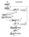
- Fig. 4 is a flowchart of stage 32 as shown in Fig. 2 for the first and second embodiments.
- the agent establishes communication with the data center computer over a standard telephone.
- the agent may communicate with the data center computer on a touch tone telephone by pressing the keys.
- Alternative embodiments may utilize a telephone communications device that includes a user or meter interface and a modem, or by voice recognition over a telephone.
- the agent first enters various codes and a password to the computer (step 70). These include a transaction code (which describes that the agent is attempting to do a remote configuration for a meter) his employee number, and his authorization code (which is a password to the data center computer for that employee).
- a transaction code which describes that the agent is attempting to do a remote configuration for a meter
- his employee number his employee number
- his authorization code which is a password to the data center computer for that employee.
- the agent then enters the meter serial number which was previously displayed by the meter but can also be found on the exterior of the meter (step 76). If the data center computer determines that the serial number is within a valid range (step 78), then the user may continue. Otherwise, the computer will notify the agent that the serial number is not within a valid range (step 79) and the agent must reenter the serial number or terminate the transaction.
- the agent then enters data previously obtained and written down above (step 84).
- this includes the BAM initialization date, the old MTN and the new MTN.
- this includes the BAM initialization date, the old MTN, the new MTN, the Ascending Register amount, and the remote setting amount.
- the agent then enters the configuration request code from the meter (step 88). From the information above, the computer is also able to generate a configuration request code (step 90). The computer checks that its configuration request code matches the configuration request code generated by the meter (step 91). If they do not match, then the agent has improperly entered numbers, the meter has been improperly reconfigured, or some other error has occurred. If the codes do not match, then the agent is notified (step 92) and must repeat the above steps starting with entering the meter serial number (step 76) or terminate the transaction.
- the computer If the two codes match, then the computer generates an encrypted configuration enable code using the current high security length (HSL) value (step 93).
- the data center computer increments the CTID located within the computer (step 94).
- the HSL value is a level of security presently utilized by the meter and data center computer which affects the length of codes passed between the meter and the data center computer (see encryption routine and Appendix D for details).
- the computer appends the HSL value to the configuration enable code and conveys the appended code to the agent (step 95).
- Fig. 5 is a flowchart of stage 34 shown above in Fig. 2.
- the agent enters the appended computer generated HSL value and configuration enable code into the meter (step 100).
- the meter then generates its own configuration enable code using the appended HSL value (step 102) and compares that code with the entered configuration enable code (step 104). If the codes do not agree, then the agent is notified (step 105) and the agent reenters the computer generated code. If the configuration enable codes agree, then the meter knows that it is authorized to reconfigure.
- the meter increments the CTID (step 106).
- the meter stores the new HSL value and the MTN in the HSL value location and the meter type number location in BAM (steps 107, 108).
- the meter also stores the five-digit remote setting amount in the remote setting amount location BAM if it was entered (step 110). The meter then clears the configuration flag (step 112), thereby allowing the meter to return from the configuration pending mode to the print mode.
- Fig. 6 is a block diagram of an alternative postage meter capable of being reconfigured in the field. Primed reference numerals are used for blocks that correspond to those in Fig. 1.
- Meter 10′ includes an external keyboard 14′ and a display 16′ to provide for user interface with the meter.
- a secure meter housing 13′ encloses a print mechanism 12′, clock 20′, registers or flip-flops 26′, and control circuitry 200.
- the control circuitry includes several controllers and other hard-wired circuits in lieu of a microprocessor as shown in Fig. 1.
- the control circuitry includes an I/O controller 202 which performs as an interface between the rest of the control circuitry and the keyboard and display.
- a data controller 204 performs as an interface between the registers and the rest of the control circuitry.
- An operations controller 206 controls the operations of the meter by executing the feature software stored in the registers. The operations controller knows which features to execute by checking the new MTN register stored in BAM.
- An inhibitor 207 checks the mode register stored in the registers to determine whether operations of the meter should be inhibited.
- a code generator/encryptor 208 continuously checks various registers in the registers and generates two encrypted codes based upon those registers.
- a code comparator 210 compares the generated codes with entered codes from the keyboard whenever such codes are entered (such as during a reconfiguration procedure). Upon a favorable comparison, the code comparator notifies a validator 212. The validator then gives a valid message through the I/O controller to the display and will instruct a CTID incrementor 214 to increment the CTID stored in the registers.
- the configuration request code and the configuration enable code are generated by an encryption routine, stored both in the meter ROM and in the data center computer.
- the encryption routine is a nonlinear algorithm that generates a number that is apparently random to an outside person.
- the encryption routine is performed by an encryption program in combination with a permanent encryption table. In the first and second embodiments, the encryption routine uses a 16 digit (or 64 bit) key and a 16 digit input number.
- the configuration request code is generated by the encryption routine performed on the CTID as the key and a combination of the old MTN and the new MTN as the input number.
- the key is composed of the meter serial number and the BAM initialization date and the input number is composed of the old MTN, the Ascending Register amount and the new MTN, and the remote setting amount.
- the configuration enable code is generated by the encryption routine performed on the CTID as the key and a combination of the old MTN, new MTN, and HSL value as the input number.
- the configuration enable code is generated by the encryption routine performed on the CTID as the key and a combination of the meter serial number and the HSL value as the input number.
- the CTID is a 16 digit number that is stored in BAM.
- the initial value of the CTID is obtained by performing an algorithm upon the BAM initialization date in combination with the meter serial number.
- the BAM initialization date is used to prevent starting with the same CTID every time the meter is initialized.
- the algorithm is not stored in the meter for security reasons.
- the initial CTID is stored in BAM during the initialization process at the factory. After the meter is reconfigured, the CTID is incremented by a nonlinear algorithm within the meter.
- the codes generated by the encryption routine are 16-digits long.
- the lower digits of the codes are then communicated to the agent by the meter or the data center computer.
- the number of lower digits that are communicated is determined by the HSL value (see Appendix D for details).
- the present invention provides a secure and efficient technique for allowing meters to be reconfigured in the field.
- the meter customer has the option of selecting features while the meter company is spared the burden of maintaining a huge inventory that would otherwise be necessary.
- the electronics of the configurable meter may be structured differently.
- a direct connection via modem can be used instead of using the tones on the telephone.
- the encryption key used to generate the request codes could be composed of a meter cycle counter instead of the meter serial number.
- Other security measures may be implemented such as requiring periodic inspection of the meter.
- This procedure is performed by an agent when installing a remote setting meter at a customer's site.
- the meter Prior to this procedure, the meter must have been reconfigured at least once since being initialized in order to establish a first link between the meter and the data center computer. In addition, the meter must be configured to include the remote setting feature. Furthermore, the meter cannot print postage until it has been installed.
- This procedure establishes a second link between the meter, the customer, and a lease on the data center computer for accounting, billing, and security purposes. This procedure also ensures that the meter has been logged into service at the post office.
- the agent or the customer takes the meter to the Post Office to register it. Once registered, the Post Office Clerk inserts a special key in the side of the meter enabling it to be installed.
- the agent Upon arriving at a customer site with the Post Office enabled meter to be installed, the agent presses a selected key sequence to put the meter in an installation mode. The meter then displays in sequence several numbers which the agent should write down for later use in this procedure.
- the meter first displays the amount stored in two of the accounting registers, the Descending Register and the Control Register.
- the Descending Register contains the amount of postage the meter presently has for printing postage.
- the Ascending Register contains the amount of postage the meter has been credited since the meter left the factory.
- the Control Register contains the sum of the Descending and Ascending Register amounts.
- the meter displays an Installation Registration Code (IRC).
- the IRC is also an encrypted number dependent upon meter specific data and may include the STID.
- the meter then prompts for an encrypted Installation Setting Code (ISC) which is dependent upon the STID.
- the agent then contacts the data center computer and enters a standard installation request code, thereby notifying the computer that the agent is in the process of performing an installation procedure.
- the agent then enters the agent's number, the agent's authorization code, the number of the customer lease for the meter, the serial number of the meter to be installed and other similar numbers.
- the computer tests the serial number for validity. If the serial number is invalid, the agent should recheck and reenter the serial number or terminate the transaction.
- the agent enters the Descending Register amount, the Control Register amount, and the IRC.
- the computer then internally generates the IRC and compares it with the meter generated IRC. If the codes are unequal for any reason, then the agent should repeat the above process beginning with entering the serial number of the meter to be installed.
- the data center computer generates and communicates the ISC, which the meter has prompted for, and increments the STID.
- the computer then internally flags that the meter is installed at the customer site.
- the agent returns to the meter and enters the computer generated ISC.
- the meter then internally generates an ISC and compares it with the entered installation code. If the codes are not equal, the meter will not accept the code. The agent may then obtain the current ISC from the data center computer again. Unlimited retries are permitted. If the codes are equal, the meter then increments the STID and sets an installation flag in BAM thereby allowing the meter to be remotely set and to print postage.
- This procedure is performed by an agent when withdrawing a remote setting meter from a customer site. This procedure removes the second link between the meter, the customer and the lease on the data center computer. In addition, this procedure prevents the meter from being remotely set. Furthermore, this procedure allows the meter to be reconfigured to change the fixed reset amount, or to a non-remote setting meter, installed at another customer site, or returned to the factory.
- the agent contacts the data center computer and enters a standard withdrawal request code, thereby notifying the central computer that the agent is in the process of performing a withdrawal procedure.
- the agent then enters the agents number, the agent's authorization code, and the serial number of the meter and other data to be withdrawn.
- the data center computer tests the serial number for validity. If the serial number is invalid, the agent should recheck and reenter the serial number. If the serial number continues to be invalid, then the meter is not properly registered on the central computer and the agent should contact the factory for further instructions.
- the agent enters a reason code.
- the reason code is a alphanumeric value which represents the reason why the meter is being withdrawn.
- the data center computer then internally generates an encrypted Withdrawal Setting Code (WSC).
- WSC Withdrawal Setting Code
- the data center computer then flags the meter as being withdrawn and increments the meter STID.
- the agent returns the meter to the factory. If the meter is functioning then the agent presses a selected key sequence to put the meter in a withdrawal mode. The agent then enters the computer generated WSC into the meter. The meter then internally generates the WSC and compares it with the computer generated WSC. If the codes are not equal, the meter will display an error message and the agent reenters the computer generated WSC. Unlimited retries are permitted. If the codes are equal, the meter then increments the STID and clears the installation flag in BAM.
- the agent or customer takes the meter to the Post Office to close the registration previously performed in the Installation Procedure (see Appendix A). Once the registration is closed, the Post Office Clerk inserts a special key in the side of the meter thereby completing the Withdrawal Procedure.
- This procedure is performed by an agent when replacing a meter at a customer's site with another meter. This procedure is merely a combination of the withdrawal of the old meter and installation of the new meter at the customer site.
- Each of the steps for the meters are the same as described in the Installation and Withdrawal Procedures (see Appendices A and B) except the agent is able to perform the procedures with only a single communication with the computer.
- An algorithm is used to generate an apparently random code with multiple digits. However, only a selected number of digits (usually the lower digits) of this code needs to be used in most applications. The number of digits needed depends upon the level of security needed. It is preferred to use as few digits as possible to decrease the number of keystrokes that must be entered, thereby increasing convenience and decreasing the potential for error.
- HSL high security length
- Each code generated by the meter or data center computer has a variable length of digits used depending upon the HSL value. That is, if the HSL value is 1, then the configuration request code should have 6 digits. If the HSL value is higher, then the configuration request code should be longer. Other codes may have different lengths for a given HSL value, but each code will increase or decrease in length if the HSL value is increased or decreased.
- This predetermined relationship between code length and the HSL value allows the meter manufacturer to increase or decrease security for the meter without having to recover and initialize each meter. Changes in the HSL value are communicated to the meter when performing a remote meter configuration.
- multiple security variables may be used to vary the lengths of individual or groups of codes without affecting the length of the remaining codes.
Abstract
If the two values agree, the data center computer generates an encrypted configuration enable code. This is communicated to the meter (10), which receives the computer generated configuration enable code and also generates an internal configuration enable code using the same algorithm as the data center computer. If the configuration enable codes agree, the meter (10) overwrites the old meter type number with the new meter type number, thereby reconfiguring the meter (10).
Description
- The present invention relates generally to postage meters and more particularly to electronic meters capable of being reconfigured.
- With the advent of electronic postage meters, it has become possible to offer meter customers a large number of optional features. Each additional feature, however, creates a larger number of possible combinations of features. Therefore, in order for a meter company to provide a large selection of features, it must maintain a large inventory of meters. This is costly and inefficient. In rental or lease markets, the inventory problem is increased by customer demands for a replacement meter of like features when the meter in service is damaged or fails.
- A customer needing to replace the meter or wanting to change the features on his meter must wait for the agent of the meter company to obtain a meter having the desired set of features. If the agent does not have a large inventory, it becomes necessary to have a meter configured at the factory. Therefore, any attempts to reduce the number of meters in the pipeline will adversely affect the length of time necessary to service the customer's request.
- The present invention provides a technique for securely reconfiguring postage meters in the field, thereby allowing variation of the features of the meter. The technique is readily implemented in the meter software. Because the technique provides security over the meter reconfiguration process, only authorized meter reconfigurations can occur. Therefore, the company will always have a correct record of the configuration of the meter in the field.
- The technique assumes that the meter has a set of features that may be selectively enabled or disabled by software. The meter is capable of being put into a configuration mode by suitable entries from the keyboard, in which mode it is inhibited from printing postage. The meter has a storage register for a current or old meter type, and can receive a desired new meter type via keyboard entry. The meter has software for generating an encrypted configuration request code that is partially based on the values of the old and new meter types. The configuration request code, when communicated to a data center computer along with other validating identification information, is checked by the data center computer which computes the configuration request code using the same algorithm. If the two values agree, the data center computer generates an encrypted configuration enable code that is partially based on the meter serial number. This is communicated to the meter, which receives the meter generated configuration enable code and also generates an internal configuration enable code using the same algorithm as the data center computer. If the configuration enable codes agree, the meter overwrites the old meter type number with the new meter type number, thereby reconfiguring the meter.
- A further understanding of the nature and advantages of the present invention can be realized by reference to the remaining portions of the specification and the attached drawings.
-
- Fig. 1 is a block diagram of a preferred postage meter capable of being reconfigured in the field;
- Fig. 2 is a high level flowchart of the process for reconfiguring the postage meter;
- Fig. 3 is a detailed flowchart of the procedure for the agent to obtain a configuration request code generated by the meter;
- Fig. 4 is a detailed flowchart of the procedure for the agent to confirm the configuration request code with the data center computer;
- Fig. 5 is a detailed flowchart of the procedure for the agent to enter the configuration enable code into the meter; and
- Fig. 6 is a block diagram of an alternative postage meter capable of being reconfigured in the field.
- Fig. 1 is a block diagram of a
preferred postage meter 10 that can be reconfigured in the field.Meter 10 includes aprint mechanism 12, accounting registers, and control electronics, all enclosed within asecure meter housing 13. Akeyboard 14 and adisplay 16 provide the user interface. Aconnector 17 provides an electrical connection with a mailing machine for control of the printing process. The control electronics includes adigital microprocessor 18 which controls the operation of the meter, including the basic functions of printing and accounting for postage, and optional features such as department accounting and remote setting. The microprocessor is connected to aclock 20, a read only memory (ROM) 22, a random access memory (RAM) 24, and a battery augmented memory (BAM) 26. -
ROM 22 is primarily used for storing nonvolatile information such as software and data/function tables necessary to run the microprocessor. The ROM can only be changed at the factory.RAM 24 is used for intermediate storage of variables and other data during meter operation. BAM 26 is primarily used to store accounting information that must be kept when the meter is powered down. The BAM is also used for storing certain flags and other information that is necessary to the functioning of the microprocessor. Such information includes meter identifying data such as the meter serial number and BAM initialization date, and a number of parameters relevant to the remote configuration of the meter. - The meter is provided with a number of features that may be enabled or disabled by software. Representative features include department accounting (with various levels of sophistication and numbers of departments that can be tracked), set date prompt, low postage warning, calculator mode variable length security codes (see Appendix D for details), and remote setting. The remote setting feature is a capability of having the meter's postage amount increased without removing the meter from the customer site. In a first embodiment of the invention, the meter postage amount can be increased by a variable amount during the remote setting process. Alternatively, in a second embodiment of the invention, the meter postage amount can be increased by a fixed increment called the fixed remote setting amount. The fixed remote setting amount may then be varied during remote configuration of the meter. Additionally, the meter may have four print wheels (maximum postage $99.99), but the high order print wheel may be disabled (maximum postage $9.99).
- In the first and second embodiments, certain meter features are hardware configured and cannot be set by software. This includes the print indicium (U.S. Postal Service or United Parcel Service) and the position of the decimal point (four-bank whole cents or four-bank decimal cents). These features may be software controlled and configurable in alternative embodiments of the invention.
- Whether a feature or a feature set is enabled is controlled by a meter type number (MTN) representing the set of features enabled. The MTN is stored in BAM and is checked by the microprocessor during meter power-up and at some branch points in the software.
- In order to simplify the software and enhance microprocessor performance in the first and second embodiments, the microprocessor performs several initialization procedures during meter power-up. In some of the initialization procedures, the microprocessor uses the MTN stored in BAM to index in RAM the software code stored in ROM to tables also stored in ROM. This indexing allows the microprocessor to more quickly read the proper tables for information without having to repeatedly determine what table to read.
- One indexed table is a Meter Selection Table which contains information regarding what features the meter has based upon the MTN and the type of meter (i.e. U.S. Postal Service or United Parcel Service, four-bank whole cents or four-bank decimal cents, etc.). Another indexed table is a Key Table which contains the address of the appropriate software code to be executed when a key is pressed by the user. The Key Table indexing is also partially based upon the MTN. After the initialization procedures are performed, the microprocessor waits for user input.
- The microprocessor is able to determine user input by periodically scanning the keyboard. As a key is pressed, x and y coordinate values are determined by the microprocessor. The microprocessor converts the x and y coordinate values to an equivalent ASCII byte. The microprocessor sends the ASCII byte to the display, which contains its own internal decoder and driver for displaying the ASCII information to the user. The microprocessor then determines what software code in ROM to execute based upon the ASCII byte by reading the indexed Key Table in ROM.
- The software code contains branch points where the microprocessor must read a table in ROM or a variable in BAM to determine which code to execute. For example, the microprocessor may read the indexed Meter Selection Table to determine whether the meter is configured to have a certain feature or not and thereby execute the appropriate code.
- Upon the execution of the appropriate software code, the microprocessor returns to a scanning state as it waits for further user input.
- In the first and second embodiments, the meter is configured to a standard feature set before leaving the factory. Because the feature set is known, the meter can be functional and still does not need to be registered on the data center computer until it has been reconfigured a first time. In an alternative embodiments, the meter can be disabled state for security reasons until it has been reconfigured a first time.
- During the reconfiguration process, the meter's serial number, present configuration and other information specific to the meter (which were already stored in the meter's memory during an initialization process at the factory) are entered on the data center computer. The meter and the computer are then able to generate identical encrypted codes by using the same encryption routine and input numbers. The encrypted codes help the data center computer maintain control over the feature set of each meter.
- Two input numbers used by the meter and the computer to generate encrypted codes are the configuration transaction identifier ("CTID") and the setting transaction identifier ("STID"). They are both specific to the meter and dependent upon the meter serial number. They may also be incremented after each use. The CTID is normally used for reconfiguring the meter functions and the STID is normally used for remote setting the meter postage. Separate numbers are used for the separate procedures in order to maximize security and minimize complexity caused by interdependence. The encryption routine is described in greater detail below.
- Fig. 2 is a high level flowchart of the process necessary for reconfiguring the postage meter by an agent at a customer's site or at the agent's technical service area. In a
first stage 30, the agent obtains a configuration request code generated by the meter. This configuration request code is essentially a password to the data center computer, and is based upon a combination of factors, the combination of which only the data center computer would know. In asecond stage 32, the agent confirms the configuration request code with the data center computer. Upon confirmation from the computer, the computer provides a configuration enable code back to the agent. The configuration enable code is essentially a password from the data center computer to the meter stating that it is permissible to reconfigure to the desired feature set. In athird stage 34, the agent enters the configuration enable code into the meter. The meter confirms the configuration enable code and reconfigures itself. - Fig. 3 is a detailed flowchart of
stage 30 for the first and second embodiments. Some meters have displays that are sophisticated and allow for user prompting. Therefore, in each of the steps described below where the meter requires certain information in order to move to the next step, some meters may prompt the agent to make that step. - In a
first step 40, the agent then puts the meter into a remote configuration mode by pressing a certain key sequence and entering a service access code. The key sequence is not obvious. This prevents customers and other unauthorized personnel from accidentally entering the configuration mode. The service access code is known to the agent and must be entered after completing the key sequence within a limited time interval that is checked by the microprocessor in combination with the clock. This further prevents customers and other unauthorized personnel from entering the configuration mode. - Upon entry of the predetermined key sequence and the agent access code, the meter enters the remote configuration mode by setting a mode register located in BAM (step 42). This prevents the meter from being used for printing purposes while being reconfigured.
- In the first embodiment, the meter then displays the meter serial number, the meter BAM initialization date, and the old meter type number (old MTN). The BAM initialization date is preferably a four digit number wherein the four digits YDDD express the date in which the meter was last initialized. The DDD stands for the number of days since December 31 and Y is the least significant digit of the year in which the meter was initialized. The old MTN is a number that defines the present feature set that the meter is presently configured to.
- In the second embodiment, the meter displays the above numbers and the Ascending Register amount or some other meter specific identifying information. The Ascending Register contains the amount of postage the meter has printed since the meter has been initialized.
- The agent then enters the new MTN into the meter (step 46). This new number represents the set of features that the meter will have after reconfiguration. The agent must then press a selected key, such as the ENTER key, followed by the service access code within a limited time interval to indicate that the entered new MTN is correct and desired. If the entered new MTN is incorrect or not desired, the agent may let the timer expire or press another selected key such as a CLEAR key. The agent then enters the correct new MTN or exits the remote configuration mode. Once the correct new MTN is entered, the agent must press the selected key (i.e., ENTER) followed by the service access code within a limited time interval to indicate that it is the correct new MTN. The meter then stores the new MTN in BAM (step 48).
- In the first and second embodiments, the meter then performs a series of tests to determine whether the meter is authorized to reconfigure to the new feature set represented by the new MTN. In the second embodiment, the meter also allows the agent to enter the fixed remote setting amount following the series of tests. The first embodiment performs steps 50-54 while the second embodiment performs steps 50-58. That is, the second embodiment performs the steps contained within the dotted
box 55 in addition to steps 50-54. - In the first and second embodiments, if the remote setting feature is being enabled or disabled (step 50), and if the Descending Register (which contains the amount of postage the meter is authorized to print) is greater than zero (step 51), then the new MTN is not accepted. The agent is notified (step 52) and the agent is able to enter a new MTN (step 46). If the meter Descending Register amount is equal to zero (step 51), the new MTN disables remote setting (step 53), and the meter installation flag is set, then the meter will not accept the new MTN for security reasons. As before, the agent is notified (step 52) and the agent is able to enter a new MTN (step 46). That is, the meter has been "installed" at a customer site by an Installation Procedure (see Appendix A) which links the meter to the post office within the data center computer. This linkage may be securely removed by a Withdrawal Procedure (see Appendix B) or an Exchange Procedure (see Appendix C).
- In the first embodiment, if the results of
step 50 is no (or false) or if the result ofstep 53 is yes (or true), then the steps in dottedbox 55 are not performed. - In the second embodiment, if the remote setting type has not changed (step 50), the new MTN includes remote setting (step 56), and the installation flag is not set (step 57), the agent enters the fixed remote setting amount. Furthermore, if the results of
step 53 is yes (or true), then the agent enters the fixed remote setting amount. - In the first and second embodiments, the meter then prompts the agent for confirmation of the new MTN. If the agent wants to start the process again with a new MTN, then the agent must press a selected key such as the CLEAR key (step 62). If the agent wants to continue, then the agent must press a selected key, such as the ENTER key, followed by the service access code or some other confirmation code (step 63). At this point, the meter puts the meter in a configuration pending mode by setting a meter configuration flag located in BAM (step 64) Once in the configuration pending mode, the meter must be reconfigured properly or else it will not return to the print mode. This prevents tampering with the reconfiguring of the meter. The meter remains in this mode even when the meter is turned off and then turned back on.
- The meter then generates and displays an encrypted meter configuration request code (step 66). In the first embodiment, the configuration request code is partially based on the CTID, the old MTN, and the new MTN. In the second embodiment, the configuration request code is partially based on the Ascending Register amount or some other meter identifying register, the old MTN, the new MTN, and the remote setting amount. The encryption process for the first and second embodiments is described in further detail below.
- Fig. 4 is a flowchart of
stage 32 as shown in Fig. 2 for the first and second embodiments. The agent establishes communication with the data center computer over a standard telephone. In the first and second embodiments, the agent may communicate with the data center computer on a touch tone telephone by pressing the keys. Alternative embodiments may utilize a telephone communications device that includes a user or meter interface and a modem, or by voice recognition over a telephone. - The agent first enters various codes and a password to the computer (step 70). These include a transaction code (which describes that the agent is attempting to do a remote configuration for a meter) his employee number, and his authorization code (which is a password to the data center computer for that employee).
- The agent then enters the meter serial number which was previously displayed by the meter but can also be found on the exterior of the meter (step 76). If the data center computer determines that the serial number is within a valid range (step 78), then the user may continue. Otherwise, the computer will notify the agent that the serial number is not within a valid range (step 79) and the agent must reenter the serial number or terminate the transaction.
- The agent then enters data previously obtained and written down above (step 84). In the first embodiment, this includes the BAM initialization date, the old MTN and the new MTN. In the second embodiment, this includes the BAM initialization date, the old MTN, the new MTN, the Ascending Register amount, and the remote setting amount.
- The agent then enters the configuration request code from the meter (step 88). From the information above, the computer is also able to generate a configuration request code (step 90). The computer checks that its configuration request code matches the configuration request code generated by the meter (step 91). If they do not match, then the agent has improperly entered numbers, the meter has been improperly reconfigured, or some other error has occurred. If the codes do not match, then the agent is notified (step 92) and must repeat the above steps starting with entering the meter serial number (step 76) or terminate the transaction.
- If the two codes match, then the computer generates an encrypted configuration enable code using the current high security length (HSL) value (step 93). The data center computer then increments the CTID located within the computer (step 94). The HSL value is a level of security presently utilized by the meter and data center computer which affects the length of codes passed between the meter and the data center computer (see encryption routine and Appendix D for details). The computer appends the HSL value to the configuration enable code and conveys the appended code to the agent (step 95).
- Fig. 5 is a flowchart of
stage 34 shown above in Fig. 2. The agent enters the appended computer generated HSL value and configuration enable code into the meter (step 100). The meter then generates its own configuration enable code using the appended HSL value (step 102) and compares that code with the entered configuration enable code (step 104). If the codes do not agree, then the agent is notified (step 105) and the agent reenters the computer generated code. If the configuration enable codes agree, then the meter knows that it is authorized to reconfigure. The meter then increments the CTID (step 106). The meter stores the new HSL value and the MTN in the HSL value location and the meter type number location in BAM (steps 107, 108). In the second embodiment, the meter also stores the five-digit remote setting amount in the remote setting amount location BAM if it was entered (step 110). The meter then clears the configuration flag (step 112), thereby allowing the meter to return from the configuration pending mode to the print mode. - Fig. 6 is a block diagram of an alternative postage meter capable of being reconfigured in the field. Primed reference numerals are used for blocks that correspond to those in Fig. 1.
-
Meter 10′ includes anexternal keyboard 14′ and adisplay 16′ to provide for user interface with the meter. Asecure meter housing 13′ encloses aprint mechanism 12′,clock 20′, registers or flip-flops 26′, andcontrol circuitry 200. The control circuitry includes several controllers and other hard-wired circuits in lieu of a microprocessor as shown in Fig. 1. - The control circuitry includes an I/
O controller 202 which performs as an interface between the rest of the control circuitry and the keyboard and display. Adata controller 204 performs as an interface between the registers and the rest of the control circuitry. Anoperations controller 206 controls the operations of the meter by executing the feature software stored in the registers. The operations controller knows which features to execute by checking the new MTN register stored in BAM. Aninhibitor 207 checks the mode register stored in the registers to determine whether operations of the meter should be inhibited. - A code generator/
encryptor 208 continuously checks various registers in the registers and generates two encrypted codes based upon those registers. Acode comparator 210 compares the generated codes with entered codes from the keyboard whenever such codes are entered (such as during a reconfiguration procedure). Upon a favorable comparison, the code comparator notifies avalidator 212. The validator then gives a valid message through the I/O controller to the display and will instruct aCTID incrementor 214 to increment the CTID stored in the registers. - In order to perform the above procedure in a secure manner and to confirm certain data, the configuration request code and the configuration enable code are generated by an encryption routine, stored both in the meter ROM and in the data center computer. The encryption routine is a nonlinear algorithm that generates a number that is apparently random to an outside person. The encryption routine is performed by an encryption program in combination with a permanent encryption table. In the first and second embodiments, the encryption routine uses a 16 digit (or 64 bit) key and a 16 digit input number.
- In the first embodiment, the configuration request code is generated by the encryption routine performed on the CTID as the key and a combination of the old MTN and the new MTN as the input number. In the second embodiment, the key is composed of the meter serial number and the BAM initialization date and the input number is composed of the old MTN, the Ascending Register amount and the new MTN, and the remote setting amount.
- In the first embodiment, the configuration enable code is generated by the encryption routine performed on the CTID as the key and a combination of the old MTN, new MTN, and HSL value as the input number. In the second embodiment, the configuration enable code is generated by the encryption routine performed on the CTID as the key and a combination of the meter serial number and the HSL value as the input number.
- The CTID is a 16 digit number that is stored in BAM. The initial value of the CTID is obtained by performing an algorithm upon the BAM initialization date in combination with the meter serial number. The BAM initialization date is used to prevent starting with the same CTID every time the meter is initialized. The algorithm is not stored in the meter for security reasons. The initial CTID is stored in BAM during the initialization process at the factory. After the meter is reconfigured, the CTID is incremented by a nonlinear algorithm within the meter.
- The codes generated by the encryption routine are 16-digits long. The lower digits of the codes are then communicated to the agent by the meter or the data center computer. The number of lower digits that are communicated is determined by the HSL value (see Appendix D for details).
- It can be seen that the present invention provides a secure and efficient technique for allowing meters to be reconfigured in the field. The meter customer has the option of selecting features while the meter company is spared the burden of maintaining a huge inventory that would otherwise be necessary.
- While the above is a complete description of specific embodiments of the invention, various modifications, alternative constructions, and equivalents may be used. For example, the electronics of the configurable meter may be structured differently. Additionally, instead of using the tones on the telephone, a direct connection via modem can be used. Furthermore, the encryption key used to generate the request codes could be composed of a meter cycle counter instead of the meter serial number. Other security measures may be implemented such as requiring periodic inspection of the meter.
- Therefore, the above description and illustration should not be taken as limiting the scope of the present invention, which is defined by the appended claims.
- This procedure is performed by an agent when installing a remote setting meter at a customer's site.
- Prior to this procedure, the meter must have been reconfigured at least once since being initialized in order to establish a first link between the meter and the data center computer. In addition, the meter must be configured to include the remote setting feature. Furthermore, the meter cannot print postage until it has been installed.
- This procedure establishes a second link between the meter, the customer, and a lease on the data center computer for accounting, billing, and security purposes. This procedure also ensures that the meter has been logged into service at the post office.
- After reconfiguring the meter, the agent or the customer takes the meter to the Post Office to register it. Once registered, the Post Office Clerk inserts a special key in the side of the meter enabling it to be installed.
- Upon arriving at a customer site with the Post Office enabled meter to be installed, the agent presses a selected key sequence to put the meter in an installation mode. The meter then displays in sequence several numbers which the agent should write down for later use in this procedure. The meter first displays the amount stored in two of the accounting registers, the Descending Register and the Control Register. The Descending Register contains the amount of postage the meter presently has for printing postage. The Ascending Register contains the amount of postage the meter has been credited since the meter left the factory. The Control Register contains the sum of the Descending and Ascending Register amounts. The meter then displays an Installation Registration Code (IRC). The IRC is also an encrypted number dependent upon meter specific data and may include the STID. The meter then prompts for an encrypted Installation Setting Code (ISC) which is dependent upon the STID.
- The agent then contacts the data center computer and enters a standard installation request code, thereby notifying the computer that the agent is in the process of performing an installation procedure. The agent then enters the agent's number, the agent's authorization code, the number of the customer lease for the meter, the serial number of the meter to be installed and other similar numbers. The computer tests the serial number for validity. If the serial number is invalid, the agent should recheck and reenter the serial number or terminate the transaction.
- If the serial number is valid, the agent enters the Descending Register amount, the Control Register amount, and the IRC. The computer then internally generates the IRC and compares it with the meter generated IRC. If the codes are unequal for any reason, then the agent should repeat the above process beginning with entering the serial number of the meter to be installed.
- The data center computer generates and communicates the ISC, which the meter has prompted for, and increments the STID. The computer then internally flags that the meter is installed at the customer site.
- The agent returns to the meter and enters the computer generated ISC. The meter then internally generates an ISC and compares it with the entered installation code. If the codes are not equal, the meter will not accept the code. The agent may then obtain the current ISC from the data center computer again. Unlimited retries are permitted. If the codes are equal, the meter then increments the STID and sets an installation flag in BAM thereby allowing the meter to be remotely set and to print postage.
- This procedure is performed by an agent when withdrawing a remote setting meter from a customer site. This procedure removes the second link between the meter, the customer and the lease on the data center computer. In addition, this procedure prevents the meter from being remotely set. Furthermore, this procedure allows the meter to be reconfigured to change the fixed reset amount, or to a non-remote setting meter, installed at another customer site, or returned to the factory.
- The agent contacts the data center computer and enters a standard withdrawal request code, thereby notifying the central computer that the agent is in the process of performing a withdrawal procedure. The agent then enters the agents number, the agent's authorization code, and the serial number of the meter and other data to be withdrawn. The data center computer tests the serial number for validity. If the serial number is invalid, the agent should recheck and reenter the serial number. If the serial number continues to be invalid, then the meter is not properly registered on the central computer and the agent should contact the factory for further instructions.
- If the serial number is valid, the agent enters a reason code. The reason code is a alphanumeric value which represents the reason why the meter is being withdrawn. The data center computer then internally generates an encrypted Withdrawal Setting Code (WSC). The data center computer then flags the meter as being withdrawn and increments the meter STID.
- If the meter is nct functional, the agent returns the meter to the factory. If the meter is functioning then the agent presses a selected key sequence to put the meter in a withdrawal mode. The agent then enters the computer generated WSC into the meter. The meter then internally generates the WSC and compares it with the computer generated WSC. If the codes are not equal, the meter will display an error message and the agent reenters the computer generated WSC. Unlimited retries are permitted. If the codes are equal, the meter then increments the STID and clears the installation flag in BAM.
- After withdrawing the meter, the agent or customer takes the meter to the Post Office to close the registration previously performed in the Installation Procedure (see Appendix A). Once the registration is closed, the Post Office Clerk inserts a special key in the side of the meter thereby completing the Withdrawal Procedure.
- This procedure is performed by an agent when replacing a meter at a customer's site with another meter. This procedure is merely a combination of the withdrawal of the old meter and installation of the new meter at the customer site. Each of the steps for the meters are the same as described in the Installation and Withdrawal Procedures (see Appendices A and B) except the agent is able to perform the procedures with only a single communication with the computer.
- An algorithm is used to generate an apparently random code with multiple digits. However, only a selected number of digits (usually the lower digits) of this code needs to be used in most applications. The number of digits needed depends upon the level of security needed. It is preferred to use as few digits as possible to decrease the number of keystrokes that must be entered, thereby increasing convenience and decreasing the potential for error.
- As a result, a variable has been created which defines the overall level of security required by the meter or data center computer. This variable is called the high security length (HSL) value.
- Each code generated by the meter or data center computer has a variable length of digits used depending upon the HSL value. That is, if the HSL value is 1, then the configuration request code should have 6 digits. If the HSL value is higher, then the configuration request code should be longer. Other codes may have different lengths for a given HSL value, but each code will increase or decrease in length if the HSL value is increased or decreased.
- This predetermined relationship between code length and the HSL value allows the meter manufacturer to increase or decrease security for the meter without having to recover and initialize each meter. Changes in the HSL value are communicated to the meter when performing a remote meter configuration.
- In an alternative embodiment, multiple security variables may be used to vary the lengths of individual or groups of codes without affecting the length of the remaining codes.
Claims (20)
Applications Claiming Priority (2)
| Application Number | Priority Date | Filing Date | Title |
|---|---|---|---|
| US328112 | 1989-03-23 | ||
| US07/328,112 US5077660A (en) | 1989-03-23 | 1989-03-23 | Remote meter configuration |
Publications (3)
| Publication Number | Publication Date |
|---|---|
| EP0388839A2 true EP0388839A2 (en) | 1990-09-26 |
| EP0388839A3 EP0388839A3 (en) | 1991-07-31 |
| EP0388839B1 EP0388839B1 (en) | 1995-03-08 |
Family
ID=23279572
Family Applications (1)
| Application Number | Title | Priority Date | Filing Date |
|---|---|---|---|
| EP90105117A Expired - Lifetime EP0388839B1 (en) | 1989-03-23 | 1990-03-19 | Remote meter configuration |
Country Status (3)
| Country | Link |
|---|---|
| US (1) | US5077660A (en) |
| EP (1) | EP0388839B1 (en) |
| DE (1) | DE69017485T2 (en) |
Cited By (8)
| Publication number | Priority date | Publication date | Assignee | Title |
|---|---|---|---|---|
| DE4344476A1 (en) * | 1993-12-21 | 1995-06-22 | Francotyp Postalia Gmbh | Process for improving the security of franking machines |
| WO1997007463A1 (en) * | 1995-08-11 | 1997-02-27 | International Business Machines Corporation | Method for verifying the configuration of a computer system |
| EP0825566A2 (en) * | 1996-08-23 | 1998-02-25 | Pitney Bowes Inc. | Electronic postage meter installation and location movement system |
| US5805711A (en) * | 1993-12-21 | 1998-09-08 | Francotyp-Postalia Ag & Co. | Method of improving the security of postage meter machines |
| EP0875865A2 (en) * | 1997-05-02 | 1998-11-04 | Neopost Limited | Postage meter with removable print head |
| EP0690417A3 (en) * | 1994-06-02 | 1999-09-15 | Neopost Industrie | Postage meter having electronic access control security |
| WO2004049134A2 (en) * | 2002-11-26 | 2004-06-10 | Neopost Industrie Sa | System and method for secure downloading |
| US6775656B1 (en) * | 1999-03-17 | 2004-08-10 | Francotyp-Postalia Ag & Co. | Method for automatic installation of franking devices and arrangement for the implementation of the method |
Families Citing this family (42)
| Publication number | Priority date | Publication date | Assignee | Title |
|---|---|---|---|---|
| US5369401A (en) * | 1989-03-23 | 1994-11-29 | F.M.E. Corporation | Remote meter operation |
| CH678368A5 (en) * | 1989-03-29 | 1991-08-30 | Frama Ag | |
| US5224046A (en) * | 1990-09-13 | 1993-06-29 | Pitney Bowes Inc. | System for recharging a plurality of postage meters |
| US5442541A (en) * | 1993-07-23 | 1995-08-15 | Xerox Corporation | Enabling features over common communication channel |
| US5905232A (en) * | 1993-10-14 | 1999-05-18 | Ascom Hasler Mailing Systems, Inc. | Electronic postage scale system and method |
| US5715164A (en) * | 1994-12-14 | 1998-02-03 | Ascom Hasler Mailing Systems Ag | System and method for communications with postage meters |
| DE4446667C2 (en) | 1994-12-15 | 1998-09-17 | Francotyp Postalia Gmbh | Process for improving the security of franking machines when transferring credit |
| US5715390A (en) * | 1995-11-30 | 1998-02-03 | General Electric Company | Method and apparatus for providing upgrades in electricity meters |
| US5974307A (en) * | 1995-12-21 | 1999-10-26 | Pitney Bowes Inc. | Method and system communicating with a voice response unit over a cellular telephone network |
| US5768383A (en) * | 1995-12-22 | 1998-06-16 | Pitney Bowes Inc. | Authorized cellular voice messaging and/or analog or digital data communication access and verification control system |
| US5765106A (en) * | 1995-12-22 | 1998-06-09 | Pitney Bowes Inc. | Authorized cellular telephone communication access and verification control system |
| US5812945A (en) * | 1995-12-22 | 1998-09-22 | Pitney Bowes Inc. | Metered payment cellular telephone communication system |
| US6035043A (en) * | 1995-12-22 | 2000-03-07 | Pitney Bowes Inc. | Cellular telephone manifest system |
| US5740247A (en) * | 1995-12-22 | 1998-04-14 | Pitney Bowes Inc. | Authorized cellular telephone communication payment refill system |
| DE19549305A1 (en) * | 1995-12-22 | 1997-07-03 | Francotyp Postalia Gmbh | Method and arrangement for entering data into a franking machine |
| US5799093A (en) * | 1996-08-23 | 1998-08-25 | Pitney Bowes Inc. | Process and apparatus for remote system inspection of a value dispensing mechanism such as a postage meter |
| US5745887A (en) * | 1996-08-23 | 1998-04-28 | Pitney Bowes Inc. | Method and apparatus for remotely changing security features of a postage meter |
| US5812990A (en) * | 1996-12-23 | 1998-09-22 | Pitney Bowes Inc. | System and method for providing an additional cryptography layer for postage meter refills |
| US6041319A (en) * | 1997-07-14 | 2000-03-21 | Pitney Bowes Inc. | Method and system for telephone updates of postal scales |
| US6018725A (en) * | 1997-09-30 | 2000-01-25 | Pitney Bowes Inc. | Method and system of implementing a carrier manager registry |
| US6910047B1 (en) | 1997-10-01 | 2005-06-21 | Pitney Bowes Inc. | Method and system for changing rating data via internet or modem in a carrier management system |
| US6873978B1 (en) | 1997-10-01 | 2005-03-29 | Pitney Bowes Inc. | Event interface for a carrier manager system |
| US6523013B2 (en) | 1998-07-24 | 2003-02-18 | Neopost, Inc. | Method and apparatus for performing automated fraud reporting |
| US6047273A (en) * | 1998-08-04 | 2000-04-04 | Vaghi Family Intellectual Properties, Llc | System and method for remotely providing mailing/shipping services to customers |
| DE10023145A1 (en) * | 2000-05-12 | 2001-11-15 | Francotyp Postalia Gmbh | Postage meter and method for releasing a postage meter |
| US20020083018A1 (en) * | 2000-12-27 | 2002-06-27 | Pitney Bowes Incorporated | Method and system for batch mail processing utilizing a web browser in a postal or shipping system |
| US20020169728A1 (en) * | 2001-02-23 | 2002-11-14 | Christian Moy | Modular franking system |
| US20040260655A1 (en) * | 2003-05-13 | 2004-12-23 | Mark Ferraro | Secure postal metering device |
| US8775997B2 (en) | 2003-09-15 | 2014-07-08 | Nvidia Corporation | System and method for testing and configuring semiconductor functional circuits |
| US8775112B2 (en) * | 2003-09-15 | 2014-07-08 | Nvidia Corporation | System and method for increasing die yield |
| US8732644B1 (en) | 2003-09-15 | 2014-05-20 | Nvidia Corporation | Micro electro mechanical switch system and method for testing and configuring semiconductor functional circuits |
| US20050080597A1 (en) * | 2003-10-10 | 2005-04-14 | Blair Timothy P. | System and method for monitoring equipment |
| US7761921B2 (en) * | 2003-10-31 | 2010-07-20 | Caterpillar Inc | Method and system of enabling a software option on a remote machine |
| US8666902B2 (en) * | 2003-12-05 | 2014-03-04 | Landis+Gyr Inc. | System and method for accessing read only ANSI tables in an electricity meter |
| US8711161B1 (en) | 2003-12-18 | 2014-04-29 | Nvidia Corporation | Functional component compensation reconfiguration system and method |
| US7844554B2 (en) * | 2004-01-23 | 2010-11-30 | Pitney Bowes Inc. | Method and system for remote feature enabling and disabling in a mailing system |
| US8723231B1 (en) * | 2004-09-15 | 2014-05-13 | Nvidia Corporation | Semiconductor die micro electro-mechanical switch management system and method |
| US20060265152A1 (en) * | 2005-05-03 | 2006-11-23 | Wall Graham D | Level measurement device operating under stored program control and including a program update module mechanism |
| US8724483B2 (en) * | 2007-10-22 | 2014-05-13 | Nvidia Corporation | Loopback configuration for bi-directional interfaces |
| US9331869B2 (en) | 2010-03-04 | 2016-05-03 | Nvidia Corporation | Input/output request packet handling techniques by a device specific kernel mode driver |
| US20140136148A1 (en) * | 2012-11-15 | 2014-05-15 | Microsoft Corporation | Automatic determination of device specific interoperability |
| US9992175B2 (en) * | 2016-01-08 | 2018-06-05 | Moneygram International, Inc. | Systems and method for providing a data security service |
Citations (7)
| Publication number | Priority date | Publication date | Assignee | Title |
|---|---|---|---|---|
| US4097923A (en) * | 1975-04-16 | 1978-06-27 | Pitney-Bowes, Inc. | Remote postage meter charging system using an advanced microcomputerized postage meter |
| EP0131967A2 (en) * | 1983-07-18 | 1985-01-23 | Pitney Bowes Inc. | Method and apparatus for customizing firmware of a postage meter and a postage meter having firmware so customized |
| WO1986005611A1 (en) * | 1985-03-15 | 1986-09-25 | Hasler Ag | Device and method for delivering and controlling predetermined amounts in a predetermined storage of a franking machine |
| GB2178696A (en) * | 1985-08-06 | 1987-02-18 | Pitney Bowes Inc | Postage metering locking system |
| US4658093A (en) * | 1983-07-11 | 1987-04-14 | Hellman Martin E | Software distribution system |
| GB2188874A (en) * | 1986-04-10 | 1987-10-14 | Pitney Bowes Inc | Postage meter recharging system |
| EP0111316B1 (en) * | 1982-12-08 | 1990-07-18 | Pitney Bowes Inc. | Apparatus and methods for controlling firmware branch points in an electronic postage meter |
Family Cites Families (30)
| Publication number | Priority date | Publication date | Assignee | Title |
|---|---|---|---|---|
| US3034329A (en) * | 1959-12-03 | 1962-05-15 | Pitney Bowes Inc | Combination lock device |
| US4182933A (en) * | 1969-02-14 | 1980-01-08 | The United States Of America As Represented By The Secretary Of The Army | Secure communication system with remote key setting |
| US3654604A (en) * | 1970-01-05 | 1972-04-04 | Constellation Science And Tech | Secure communications control system |
| US3798359A (en) * | 1971-06-30 | 1974-03-19 | Ibm | Block cipher cryptographic system |
| US3798360A (en) * | 1971-06-30 | 1974-03-19 | Ibm | Step code ciphering system |
| US3792446A (en) * | 1972-12-04 | 1974-02-12 | Pitney Bowes Inc | Remote postage meter resetting method |
| US3800284A (en) * | 1973-01-12 | 1974-03-26 | Pitney Bowes Inc | Electronic combination lock and lock system |
| US3860911A (en) * | 1973-11-01 | 1975-01-14 | Pitney Bowes Inc | Electronic combination lock and lock system |
| DE2636852C2 (en) * | 1976-08-16 | 1982-05-27 | Postalia Gmbh, 6050 Offenbach | Arrangement for the central recording of the postage franking fees to be paid for mail items through the use of franking machines |
| US4310720A (en) * | 1978-03-31 | 1982-01-12 | Pitney Bowes Inc. | Computer accessing system |
| US4222518A (en) * | 1978-10-19 | 1980-09-16 | Simjian Luther G | Metering system |
| US4226360A (en) * | 1978-12-19 | 1980-10-07 | Simjian Luther G | Metering system |
| US4249071A (en) * | 1979-02-27 | 1981-02-03 | Simjian Luther G | Metering system |
| US4253158A (en) * | 1979-03-28 | 1981-02-24 | Pitney Bowes Inc. | System for securing postage printing transactions |
| US4484307A (en) * | 1979-05-09 | 1984-11-20 | F.M.E. Corporation | Electronic postage meter having improved security and fault tolerance features |
| US4280180A (en) * | 1979-10-30 | 1981-07-21 | Pitney Bowes Inc. | Electronic postage meter having field resettable control values |
| US4302821A (en) * | 1979-10-30 | 1981-11-24 | Pitney-Bowes, Inc. | Interposer control for electronic postage meter |
| US4314097A (en) * | 1980-03-10 | 1982-02-02 | Burroughs Corporation | Authenticator device for precluding compensating text modifications in transmitted messages |
| FR2486687B1 (en) * | 1980-07-09 | 1986-08-22 | Roneo Alcatel Ltd | POSTAL POSTAGE COUNTER |
| US4376299A (en) * | 1980-07-14 | 1983-03-08 | Pitney Bowes, Inc. | Data center for remote postage meter recharging system having physically secure encrypting apparatus and employing encrypted seed number signals |
| US4447890A (en) * | 1980-07-14 | 1984-05-08 | Pitney Bowes Inc. | Remote postage meter systems having variable user authorization code |
| US4424573A (en) * | 1981-02-26 | 1984-01-03 | Pitney Bowes Inc. | System for entering a postage meter serial number into a nonvolatile memory from an external channel after assembly of the meter |
| US4562535A (en) * | 1982-04-05 | 1985-12-31 | Texas Instruments Incorporated | Self-configuring digital processor system with global system |
| US4775931A (en) * | 1984-05-11 | 1988-10-04 | Hewlett-Packard Company | Dynamically configured computing device |
| US4580144A (en) * | 1984-08-20 | 1986-04-01 | Pitney Bowes Inc. | Postal fixed and variable data thermal printer |
| US4775246A (en) * | 1985-04-17 | 1988-10-04 | Pitney Bowes Inc. | System for detecting unaccounted for printing in a value printing system |
| US4812994A (en) * | 1985-08-06 | 1989-03-14 | Pitney Bowes Inc. | Postage meter locking system |
| US4783745A (en) * | 1986-01-30 | 1988-11-08 | Pitney Bowes Inc. | Nonvolatile memory unlock for an electronic postage meter |
| US4812992A (en) * | 1986-04-10 | 1989-03-14 | Pitney Bowes Inc. | Postage meter communication system |
| US4837714A (en) * | 1986-04-18 | 1989-06-06 | Pitney Bowes, Inc. | Methods and apparatus for customizing and testing fully assembled postage meters |
-
1989
- 1989-03-23 US US07/328,112 patent/US5077660A/en not_active Expired - Lifetime
-
1990
- 1990-03-19 EP EP90105117A patent/EP0388839B1/en not_active Expired - Lifetime
- 1990-03-19 DE DE69017485T patent/DE69017485T2/en not_active Expired - Lifetime
Patent Citations (7)
| Publication number | Priority date | Publication date | Assignee | Title |
|---|---|---|---|---|
| US4097923A (en) * | 1975-04-16 | 1978-06-27 | Pitney-Bowes, Inc. | Remote postage meter charging system using an advanced microcomputerized postage meter |
| EP0111316B1 (en) * | 1982-12-08 | 1990-07-18 | Pitney Bowes Inc. | Apparatus and methods for controlling firmware branch points in an electronic postage meter |
| US4658093A (en) * | 1983-07-11 | 1987-04-14 | Hellman Martin E | Software distribution system |
| EP0131967A2 (en) * | 1983-07-18 | 1985-01-23 | Pitney Bowes Inc. | Method and apparatus for customizing firmware of a postage meter and a postage meter having firmware so customized |
| WO1986005611A1 (en) * | 1985-03-15 | 1986-09-25 | Hasler Ag | Device and method for delivering and controlling predetermined amounts in a predetermined storage of a franking machine |
| GB2178696A (en) * | 1985-08-06 | 1987-02-18 | Pitney Bowes Inc | Postage metering locking system |
| GB2188874A (en) * | 1986-04-10 | 1987-10-14 | Pitney Bowes Inc | Postage meter recharging system |
Cited By (12)
| Publication number | Priority date | Publication date | Assignee | Title |
|---|---|---|---|---|
| DE4344476A1 (en) * | 1993-12-21 | 1995-06-22 | Francotyp Postalia Gmbh | Process for improving the security of franking machines |
| US5671146A (en) * | 1993-12-21 | 1997-09-23 | Francotyp-Postalia Gmbh | Method for improving the security of postage meter machines |
| US5805711A (en) * | 1993-12-21 | 1998-09-08 | Francotyp-Postalia Ag & Co. | Method of improving the security of postage meter machines |
| EP0690417A3 (en) * | 1994-06-02 | 1999-09-15 | Neopost Industrie | Postage meter having electronic access control security |
| WO1997007463A1 (en) * | 1995-08-11 | 1997-02-27 | International Business Machines Corporation | Method for verifying the configuration of a computer system |
| EP0825566A2 (en) * | 1996-08-23 | 1998-02-25 | Pitney Bowes Inc. | Electronic postage meter installation and location movement system |
| EP0825566A3 (en) * | 1996-08-23 | 2000-04-12 | Pitney Bowes Inc. | Electronic postage meter installation and location movement system |
| EP0875865A2 (en) * | 1997-05-02 | 1998-11-04 | Neopost Limited | Postage meter with removable print head |
| EP0875865A3 (en) * | 1997-05-02 | 2000-11-15 | Neopost Limited | Postage meter with removable print head |
| US6775656B1 (en) * | 1999-03-17 | 2004-08-10 | Francotyp-Postalia Ag & Co. | Method for automatic installation of franking devices and arrangement for the implementation of the method |
| WO2004049134A2 (en) * | 2002-11-26 | 2004-06-10 | Neopost Industrie Sa | System and method for secure downloading |
| WO2004049134A3 (en) * | 2002-11-26 | 2004-09-23 | Neopost Ind Sa | System and method for secure downloading |
Also Published As
| Publication number | Publication date |
|---|---|
| EP0388839B1 (en) | 1995-03-08 |
| DE69017485D1 (en) | 1995-04-13 |
| DE69017485T2 (en) | 1995-07-20 |
| US5077660A (en) | 1991-12-31 |
| EP0388839A3 (en) | 1991-07-31 |
Similar Documents
| Publication | Publication Date | Title |
|---|---|---|
| US5077660A (en) | Remote meter configuration | |
| US5369401A (en) | Remote meter operation | |
| US5107455A (en) | Remote meter i/o configuration | |
| EP0328059B1 (en) | Postal charge accounting system | |
| US4812994A (en) | Postage meter locking system | |
| US5058025A (en) | Emergency post office setting for remote setting meter | |
| US5699415A (en) | Method for matching the database between an electronic postage meter machine and a data center | |
| US5778076A (en) | System and method for controlling the dispensing of an authenticating indicia | |
| CA2148648C (en) | Advance postage payment system employing pre-computed digital tokens and with enhanced security | |
| CA1320578C (en) | Automated transaction system using microprocessor cards | |
| EP0780805B1 (en) | Open metering system with super password vault access | |
| EP0942398B1 (en) | Method and system for changing an encryption key in a mail processing system having a postage meter and a security center | |
| US4783745A (en) | Nonvolatile memory unlock for an electronic postage meter | |
| EP0782110A2 (en) | System and method for managing multiple users with different privileges in an open metering system | |
| EP0862142B1 (en) | Franking machine | |
| JPS6258388A (en) | Price printing apparatus and method | |
| EP0825566B1 (en) | Electronic postage meter installation and location movement system | |
| EP0388840B1 (en) | Security extension procedure for electronic remote setting meter | |
| EP0604147A2 (en) | Franking machine and method of franking | |
| CA1263752A (en) | Postage meter locking system | |
| EP0825564A2 (en) | Process and apparatus for remote system inspection of a value dispensing mechanism such as a postage meter | |
| EP1022684B1 (en) | Method of limiting key usage in a postage metering system that produces cryptographically secured indicium | |
| EP0848353B1 (en) | Method and apparatus for automatically disabling a removable, portable vault of a postage metering system | |
| US4835697A (en) | Combination generator for an electronic postage meter | |
| EP0493943B1 (en) | Postage meter monitoring and control |
Legal Events
| Date | Code | Title | Description |
|---|---|---|---|
| PUAI | Public reference made under article 153(3) epc to a published international application that has entered the european phase |
Free format text: ORIGINAL CODE: 0009012 |
|
| AK | Designated contracting states |
Kind code of ref document: A2 Designated state(s): DE FR GB |
|
| PUAL | Search report despatched |
Free format text: ORIGINAL CODE: 0009013 |
|
| AK | Designated contracting states |
Kind code of ref document: A3 Designated state(s): DE FR GB |
|
| 17P | Request for examination filed |
Effective date: 19920120 |
|
| RAP1 | Party data changed (applicant data changed or rights of an application transferred) |
Owner name: NEOPOST INDUSTRIE |
|
| 17Q | First examination report despatched |
Effective date: 19930621 |
|
| GRAA | (expected) grant |
Free format text: ORIGINAL CODE: 0009210 |
|
| AK | Designated contracting states |
Kind code of ref document: B1 Designated state(s): DE FR GB |
|
| REF | Corresponds to: |
Ref document number: 69017485 Country of ref document: DE Date of ref document: 19950413 |
|
| ET | Fr: translation filed | ||
| PLBE | No opposition filed within time limit |
Free format text: ORIGINAL CODE: 0009261 |
|
| STAA | Information on the status of an ep patent application or granted ep patent |
Free format text: STATUS: NO OPPOSITION FILED WITHIN TIME LIMIT |
|
| 26N | No opposition filed | ||
| REG | Reference to a national code |
Ref country code: GB Ref legal event code: IF02 |
|
| PGFP | Annual fee paid to national office [announced via postgrant information from national office to epo] |
Ref country code: GB Payment date: 20090325 Year of fee payment: 20 |
|
| PGFP | Annual fee paid to national office [announced via postgrant information from national office to epo] |
Ref country code: DE Payment date: 20090320 Year of fee payment: 20 |
|
| PGFP | Annual fee paid to national office [announced via postgrant information from national office to epo] |
Ref country code: FR Payment date: 20090312 Year of fee payment: 20 |
|
| REG | Reference to a national code |
Ref country code: GB Ref legal event code: PE20 Expiry date: 20100318 |
|
| PG25 | Lapsed in a contracting state [announced via postgrant information from national office to epo] |
Ref country code: GB Free format text: LAPSE BECAUSE OF EXPIRATION OF PROTECTION Effective date: 20100318 |
|
| PG25 | Lapsed in a contracting state [announced via postgrant information from national office to epo] |
Ref country code: DE Free format text: LAPSE BECAUSE OF EXPIRATION OF PROTECTION Effective date: 20100319 |