EP0392927A2 - Vertebral implant for osteosynthesis device - Google Patents
Vertebral implant for osteosynthesis device Download PDFInfo
- Publication number
- EP0392927A2 EP0392927A2 EP90401002A EP90401002A EP0392927A2 EP 0392927 A2 EP0392927 A2 EP 0392927A2 EP 90401002 A EP90401002 A EP 90401002A EP 90401002 A EP90401002 A EP 90401002A EP 0392927 A2 EP0392927 A2 EP 0392927A2
- Authority
- EP
- European Patent Office
- Prior art keywords
- screw
- blocker
- implant
- rod
- channel
- Prior art date
- Legal status (The legal status is an assumption and is not a legal conclusion. Google has not performed a legal analysis and makes no representation as to the accuracy of the status listed.)
- Granted
Links
Images


Classifications
-
- A—HUMAN NECESSITIES
- A61—MEDICAL OR VETERINARY SCIENCE; HYGIENE
- A61B—DIAGNOSIS; SURGERY; IDENTIFICATION
- A61B17/00—Surgical instruments, devices or methods, e.g. tourniquets
- A61B17/56—Surgical instruments or methods for treatment of bones or joints; Devices specially adapted therefor
- A61B17/58—Surgical instruments or methods for treatment of bones or joints; Devices specially adapted therefor for osteosynthesis, e.g. bone plates, screws, setting implements or the like
- A61B17/68—Internal fixation devices, including fasteners and spinal fixators, even if a part thereof projects from the skin
- A61B17/70—Spinal positioners or stabilisers ; Bone stabilisers comprising fluid filler in an implant
- A61B17/7001—Screws or hooks combined with longitudinal elements which do not contact vertebrae
- A61B17/7032—Screws or hooks with U-shaped head or back through which longitudinal rods pass
- A61B17/7034—Screws or hooks with U-shaped head or back through which longitudinal rods pass characterised by a lateral opening
-
- A—HUMAN NECESSITIES
- A61—MEDICAL OR VETERINARY SCIENCE; HYGIENE
- A61B—DIAGNOSIS; SURGERY; IDENTIFICATION
- A61B17/00—Surgical instruments, devices or methods, e.g. tourniquets
- A61B17/56—Surgical instruments or methods for treatment of bones or joints; Devices specially adapted therefor
- A61B17/58—Surgical instruments or methods for treatment of bones or joints; Devices specially adapted therefor for osteosynthesis, e.g. bone plates, screws, setting implements or the like
- A61B17/68—Internal fixation devices, including fasteners and spinal fixators, even if a part thereof projects from the skin
- A61B17/70—Spinal positioners or stabilisers ; Bone stabilisers comprising fluid filler in an implant
- A61B17/7001—Screws or hooks combined with longitudinal elements which do not contact vertebrae
- A61B17/7032—Screws or hooks with U-shaped head or back through which longitudinal rods pass
Definitions
- the present invention relates to a vertebral implant for an osteosynthesis device.
- this implant is of the type comprising a bone anchoring element, constituted by a screw or by a curved blade forming a hook, a body having a channel adapted to be crossed by a rod, and a first screw for securing the implant with the rod, this screw having its axis perpendicular to the rod against which it is tightened, either through the body, or through a blocker which can slide on the rod and come to be housed in the body.
- the openings allow the direct insertion of the rod into the channel of the body of the implant.
- the rod-implant fixation is obtained by means of an intermediate piece called a blocker, formed of a ring of which one half is conical, and the other half cylindrical, surmounted by tapped square body for the passage of a locking screw and the fixing in rotation (aforementioned patent 83 07 450).
- the rod fitted with its blocker is inserted into the channel of the implant which impaled on the blocker, ensuring after screwing of the latter an implant-rod fixation.
- an additional part called a safety lock is necessary. It consists of a ring with lateral opening for passage of the rod, provided with two arms partially enclosing the body of the implant and screwed directly onto the rod.
- This prior device essentially consists of three relatively bulky parts (hook, bolt and blocker). This results in a certain difficulty of assembly, in particular at the junction of the lumbar and sacral regions where a small space remains available due to the anatomical conditions.
- the object of the invention is therefore to produce an implant in which these drawbacks are eliminated, and which secures the rod in the body of the implant more solid than that obtained in the device of French patent 83 07 450.
- the vertebral implant comprises at least a second rod locking screw passing through the body laterally to the first screw and engaged in a tapped hole inclined on the axis of said first screw, these two screws being located substantially in the same plane perpendicular to the axis of the channel and the rod.
- two tapped holes having their axes inclined on the axis of the first screw are formed in the body on each side of the first screw, to receive corresponding locking screws.
- the implant does not have a blocker, and the two or three aforementioned screws pass through tapped holes made in the body.
- the implant is equipped with a blocker which can be housed inside the body and is provided with the first central screw, on both sides. 'other of which are placed the two oblique lateral screws, which are screwed directly on the rod through holes drilled in the branches of the body and in the blocker.
- the rod can be fixed in the implant by three screws, namely the two oblique lateral screws and the screw of the blocker.
- This implant therefore no longer has a lock, unlike the device of the aforementioned prior patent, while guaranteeing attachment to the rod in all directions and with greater solidity than previously.
- the size of the implant thus produced is therefore significantly reduced, which facilitates its installation by the surgeon, in particular in the lumbar and sacral regions.
- the vertebral implant shown in Figs. 1 to 3 is intended for an osteosynthesis device for spine surgery.
- This implant 1 comprises a bone anchoring element 2, here constituted by a screw of suitable dimensions and thread.
- the implant 1 also comprises a one-piece body 3 with the screw 2 and which has a central channel 4 adapted to be crossed by a rod 5 whose surface can be smooth or with roughness, for example covered with diamond tips.
- the body 3 is of the posterior opening type 6, coaxial with the axis XX of the implant 1, and delimited by two branches 3a and 3b, the inner surfaces of which form edges for the channel 4.
- the implant 1 is provided with an annular blocker 20 consisting of a cylindrical ring 7, a radial extension 8 projecting from the ring 7, and a screw 9 which can be screwed into a tapped hole in the extension 8 to be applied on the surface of the rod 5.
- the internal diameter of the ring 7 is slightly greater than the diameter of the rod 5 so that the blocker 20 can slide thereon, and this blocker is sized to be able to come engage in channel 4 with its extension 8 placed between the ends of the branches 3a, 3b in the rear opening 6.
- the ring 7 is provided with a frustoconical front part 7a adapted to come into abutment in abutment against a complementary frustoconical part 11 of the channel 4.
- the implant 1 is equipped with locking means on the rod 5 complementary to the first central screw 9.
- These means are constituted, in the example described, by a second and a third screw 12, 13 passing through the respective branches 3a, 3b from the body 3 laterally to the first screw 9 and on each side thereof, relative to the axis of which they are inclined by an appropriate angle A.
- the screws 12, 13 are screwed into corresponding tapped holes 12a, 13a of inclination A on the axis XX of the implant 1 and of the screw 9.
- the two locking screws 12 and 13 are located substantially in the same plane perpendicular to the axis YY of the channel 4 and the rod 5, that is to say the plane of Fig.1.
- the implant 1 could only be equipped with a screw 12 or 13 associated with a single tapped hole, or even only one of the screws 12 and 13 can be placed in the implant 1, in some cases of difficult placement in regions of the spine where space is limited.
- hollow recesses 12b, 13b suitably profiled to receive a screwing tool, are formed in the heads of the screws 12 and 13.
- the implementation of the implant 1 which has just been described on its rod 5 is carried out in a very simple manner: the blocker 20 being previously mounted freely sliding on the rod 5, the latter is introduced into the channel 4 by the rear opening 6. Then slide the blocker 20 until it enters between the branches 3a and 3b and that its conical part 7a abuts against the complementary part 11. The screws 9 and 12, 13 are then successively screwed, the latter two passing through respective holes such as 14, symmetrical with respect to the 'axis XX.
- this implant in the direction of the rod 5 is greatly reduced compared to that of the implant described in French patent 83 07 450, in particular thanks to the removal of the lock. Furthermore, it should be noted that the walls or branches 3a, 3b of the body 3 are thickened relative to those of the body of the hook described in the aforementioned French patent, in order to increase their mechanical strength. They are also rounded in order to reduce or eliminate sharp angles likely to injure the patient's tissues.
- the reduction in size of the implant 1 is particularly advantageous in cases where its volume can make instrumentation difficult or impossible, for anatomical reasons, such as at the sacrum.
- screws 12, 13 without head having recesses 12b, 13b for example hexagonal of the M3HC type (French patent 87 16 209) it is possible to remove the implanted material by unscrewing the two screws 12 and 13 as well as the central screw 9.
- the implant 15 shown in Figs 4 to 6 differs from the implant 1 in that the rear opening 6 is here replaced by a lateral opening 16 whose axis ZZ is inclined on the axis XX of the implant 15 at an appropriate angle, for example 25 or 30 °. (These values are naturally given only as a non-limiting indication and can vary widely).
- the opening 16 and the channel 4 are therefore here delimited by lateral branches 3aa and 3bb of unequal lengths, the branch 3aa being shorter than the branch 3bb. Therefore the two tapped holes 17, 18 formed in the branches 3aa and 3bb and their corresponding screws 19, 21, inclined on the axis ZZ and symmetrical with respect thereto, have different inclinations on the axis XX.
- the implementation of the implant 15, which includes a blocker not shown and similar to the blocker 6, is done in the same way as that of the implant 1.
- the implant 15 may have only one tapped hole 17 or 18, or have two, but be implemented with only one of the screws 19 and 21.
- the bottom of the channel 4 can be connected to the end of the screw 2 by an axial conduit 22 for guiding the implantation of the screw and of the body, on a rod not shown, threaded in this conduit 22.
- the screw 2 is replaced by a screw 2a inclined at an appropriate angle on the axis XX and therefore forming with the body 3 an obtuse angle.
- the implant thus produced is suitable for use in the sacrum for oblique fixation.
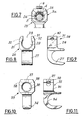
- the third embodiment of the implant 23 shown in Fig.7 comprises a closed body 3a, therefore deprived of a blocker.
- the central screw 9 is introduced here through the body 3a in the central position as in the previous embodiments, and screwed onto the rod 5, on which also apply two oblique screws 24, 25 symmetrical with respect to the screw 9 and which go through corresponding tapped holes of the body 3a.
- the implant 26 of FIGS. 8 and 9 is a hook formed by a curved blade 27 and a body with posterior opening 28 and channel 29 delimited by two branches 31 pierced by two oblique tapped holes 32 for receiving screws not shown (nor the blocker, similar to the blocker 20).
- the implant of Figs. 10 and 11 is also a hook 33 with a blade 34 but its body 35 is closed. It is pierced with a channel 36 and three tapped holes 37, 38 for the passage of the screws.
- frustoconical parts 7a and 11 can be replaced by any suitable male and female parts.
- the blocker 40 is annular and provided at one of its ends with a stop 41 projecting radially.
- This stop 41 can thus be in the form of a collar adapted to come to bear on the body 42 of the implant 43 and more precisely on one of the ends of its channel 44, the body 42 being of the open type with its channel 44 delimited by two lateral branches 45.
- the stop 41 has the function, by coming into abutment against the entry edge of the channel 44, to correctly position the blocker 40 in the body 42, so that the tapped holes 46 for passage lateral screws in the blocker 40 come in precise correspondence with the holes 47 of the body 42.
- Chamfers 48 can advantageously be formed on the opposite edges of the openings of the channel 44, to facilitate the introduction of the blocker 40 into the body 42.
- the end of the blocker 40 opposite its end carrying the stop 41 has a complementary chamfer 49 while the abutment 41 is profiled in a bevel or conical chamfer so as to be able to be applied to one of the chamfers 48 at the entrance to channel 44.
- the stop 41 may be for example circular, or with a square section.
- the channel 44 being cylindrical over its entire length and widened at each of its ends by a chamfer 48, it becomes possible to introduce the blocker 40 into the body 42 through one or other of the openings of the channel 44.
- the blocker 50 shown in FIGS. 15 to 17 is produced in the form of a jumper with two legs 51 which delimit between them a channel 52 open radially in the direction opposite to the central screw 9.
- the lateral legs 51 and the semicircular profile of the channel 52 are adapted to cover the rod (not shown) by enclosing it between the legs 51.
- the blocker 50 is further provided with a stop projecting radially, in this example being in the form of two lateral protuberances 53 adapted to come into abutment on the body of the implant, in order to adequately position with respect to the latter the blocker 50.
- the protrusions 53 are produced so that their surfaces come to tangent the ends of the legs 51.
- a bevel 54 is formed on each side of the end of the blocker 50 opposite its end carrying the abutment protrusions 53. The bevelled parts 54 facilitate the introduction of the blocker 50 into the body of the implant.
Landscapes
- Health & Medical Sciences (AREA)
- Orthopedic Medicine & Surgery (AREA)
- Life Sciences & Earth Sciences (AREA)
- Neurology (AREA)
- Surgery (AREA)
- Heart & Thoracic Surgery (AREA)
- Engineering & Computer Science (AREA)
- Biomedical Technology (AREA)
- Nuclear Medicine, Radiotherapy & Molecular Imaging (AREA)
- Medical Informatics (AREA)
- Molecular Biology (AREA)
- Animal Behavior & Ethology (AREA)
- General Health & Medical Sciences (AREA)
- Public Health (AREA)
- Veterinary Medicine (AREA)
- Prostheses (AREA)
- Surgical Instruments (AREA)
Abstract
Description
La présente invention a pour objet un implant vertébral pour dispositif d'ostéosynthèse.The present invention relates to a vertebral implant for an osteosynthesis device.
Plus précisément, cet implant est du type comprenant un élément d'ancrage osseux, constitué par une vis ou par une lame recourbée formant crochet, un corps présentant un canal adapté pour être traversé par une tige, et une première vis de solidarisation de l'implant avec la tige, cette vis ayant son axe perpendiculaire à la tige contre laquelle elle est serrée, soit à travers le corps, soit à travers un bloqueur pouvant coulisser sur la tige et venir se loger dans le corps.More specifically, this implant is of the type comprising a bone anchoring element, constituted by a screw or by a curved blade forming a hook, a body having a channel adapted to be crossed by a rod, and a first screw for securing the implant with the rod, this screw having its axis perpendicular to the rod against which it is tightened, either through the body, or through a blocker which can slide on the rod and come to be housed in the body.
Il est connu, dans des dispositifs d'ostéosynthèse rachidienne, de mettre en oeuvre des tiges métalliques à aspérités de surface qui permettent la fixation de crochets, comme décrit par le brevet français 83 07 450 (2 545 350) ou de vis comme décrit par le brevet français 87 03 485. Cette fixation peut être effectuée dans toutes les positions de niveau, dans tous les sens et dans toutes les directions, au moyen d'une ou deux vis de blocage vissées à travers le corps de l'implant sur la tige. Le corps des crochets et des vis est, soit fermé autour de son canal de passage de la tige, soit à ouverture postérieure, soit à ouverture latérale débouchant dans le canal.It is known, in spinal osteosynthesis devices, to use metal rods with surface roughness which allow the attachment of hooks, as described by French patent 83 07 450 (2 545 350) or screws as described by French patent 87 03 485. This fixing can be carried out in all level positions, in all directions and in all directions, by means of one or two locking screws screwed through the body of the implant onto the rod. The body of the hooks and screws is either closed around its rod passage channel, or with posterior opening, or with lateral opening opening into the channel.
Les ouvertures permettent l'insertion directe de la tige dans le canal du corps de l'implant. Dans le cas d'un implant à ouverture postérieure, la fixation tige-implant est obtenue au moyen d'une pièce intermédiaire dite bloqueur, formée d'un anneau dont une moitié est conique, et l'autre moitié cylindrique, surmonté d'un corps carré taraudé pour le passage d'une vis de blocage et la fixation en rotation (brevet précité 83 07 450).The openings allow the direct insertion of the rod into the channel of the body of the implant. In the case of an implant with posterior opening, the rod-implant fixation is obtained by means of an intermediate piece called a blocker, formed of a ring of which one half is conical, and the other half cylindrical, surmounted by tapped square body for the passage of a locking screw and the fixing in rotation (aforementioned patent 83 07 450).
La tige munie de son bloqueur est insérée dans le canal de l'implant qui vient s'empaler sur le bloqueur, assurant après vissage de ce dernier une fixation implant-tige. Pour éviter tout déplacement de l'implant sur son bloqueur du côté de l'extrémité conique de celui-ci, une pièce complémentaire dite verrou de sûreté, est nécessaire. Elle est constituée d'un anneau à ouverture latérale de passage de la tige, munie de deux bras enserrant partiellement le corps de l'implant et vissée directement sur la tige.The rod fitted with its blocker is inserted into the channel of the implant which impaled on the blocker, ensuring after screwing of the latter an implant-rod fixation. To avoid any displacement of the implant on its blocker on the side of the conical end thereof, an additional part called a safety lock is necessary. It consists of a ring with lateral opening for passage of the rod, provided with two arms partially enclosing the body of the implant and screwed directly onto the rod.
Ce dispositif antérieur est constitué essentiellement de trois pièces (crochet, verrou et bloqueur) relativement encombrantes. Il en résulte une certaine difficulté de montage, en particulier à la jonction des régions lombaires et sacrées où un faible espace reste disponible en raison des conditions anatomiques.This prior device essentially consists of three relatively bulky parts (hook, bolt and blocker). This results in a certain difficulty of assembly, in particular at the junction of the lumbar and sacral regions where a small space remains available due to the anatomical conditions.
De plus dans ce dispositif antérieur, un risque de glissement éventuel du bloqueur par rapport au crochet de l'implant ne peut être totalement écarté, bien que ce soit là précisément la fonction du verrou de sûreté.In addition, in this prior device, a risk of possible sliding of the blocker relative to the implant hook cannot be completely ruled out, although this is precisely the function of the safety lock.
L'invention a donc pour but de réaliser un implant dans lequel ces inconvénients sont éliminés, et qui assure une fixation de la tige dans le corps de l'implant plus solide que celle obtenue dans le dispositif du brevet français 83 07 450.The object of the invention is therefore to produce an implant in which these drawbacks are eliminated, and which secures the rod in the body of the implant more solid than that obtained in the device of French patent 83 07 450.
Suivant l'invention, l'implant vertébral comprend au moins une seconde vis de blocage de la tige, traversant le corps latéralement à la première vis et engagée dans un trou taraudé incliné sur l'axe de ladite première vis, ces deux vis étant situées sensiblement dans un même plan perpendiculaire à l'axe du canal et de la tige.According to the invention, the vertebral implant comprises at least a second rod locking screw passing through the body laterally to the first screw and engaged in a tapped hole inclined on the axis of said first screw, these two screws being located substantially in the same plane perpendicular to the axis of the channel and the rod.
Selon un mode de réalisation possible, deux trous taraudés ayant leurs axes inclinés sur l'axe de la première vis sont ménagés dans le corps de chaque côté de la première vis, pour recevoir des vis de blocage correspondantes.According to a possible embodiment, two tapped holes having their axes inclined on the axis of the first screw are formed in the body on each side of the first screw, to receive corresponding locking screws.
Si le corps est du type fermé, l'implant ne comporte pas de bloqueur, et les deux ou trois vis précitées traversent des trous taraudés ménagés dans le corps. Si le corps est du type à ouverture postérieure ou latérale, débouchant dans le canal, l'implant est équipé d'un bloqueur qui peut venir se loger à l'intérieur du corps et est pourvu de la première vis centrale, de part et d'autre de laquelle sont placées les deux vis latérales obliques, qui sont vissées directement sur la tige à travers des trous percés dans les branches du corps et dans le bloqueur.If the body is of the closed type, the implant does not have a blocker, and the two or three aforementioned screws pass through tapped holes made in the body. If the body is of the type with posterior or lateral opening, opening into the canal, the implant is equipped with a blocker which can be housed inside the body and is provided with the first central screw, on both sides. 'other of which are placed the two oblique lateral screws, which are screwed directly on the rod through holes drilled in the branches of the body and in the blocker.
Avantageusement, la tige peut être fixée dans l'implant par trois vis, à savoir les deux vis latérales obliques et la vis du bloqueur.Advantageously, the rod can be fixed in the implant by three screws, namely the two oblique lateral screws and the screw of the blocker.
Cet implant ne comporte donc plus de verrou, contrairement au dispositif du brevet antérieur précité, tout en garantissant une fixation sur la tige dans tous les sens et avec une plus grande solidité que précédemment. L'encombrement de l'implant ainsi réalisé est donc notablement réduit, ce qui facilite sa mise en place par le chirurgien, en particulier dans les régions lombaires et sacrées.This implant therefore no longer has a lock, unlike the device of the aforementioned prior patent, while guaranteeing attachment to the rod in all directions and with greater solidity than previously. The size of the implant thus produced is therefore significantly reduced, which facilitates its installation by the surgeon, in particular in the lumbar and sacral regions.
D'autres particularités et avantages de l'invention apparaîtront au cours de la description qui va suivre, faite en référence aux dessins annexés qui en illustrent plusieurs formes de réalisation à titre d'exemples non-limitatifs.
- La figure 1 est une vue en élévation d'une première forme de réalisation de l'implant vertébral selon l'invention, monté sur la tige correspondante.
- La figure 2 est une vue en élévation selon la flèche K de la Fig.1.
- La figure 3 est une vue de dessus de l'implant des. Fig.1 et 2.
- La figure 4 est une vue en élévation d'une seconde forme de réalisation de l'implant selon l'invention.
- La figure 5 est une vue en élévation dans la direction de la flèche L de la Fig.4, et montre également, en traits mixtes, une variante de réalisation possible de cet implant.
- La figure 6 est une vue de dessus de l'implant des Fig.4 et 5.
- La figure 7 est une vue en élévation partielle analogue à la Fig.1 d'une troisième forme de réalisation de l'implant selon l'invention.
- La figure 8 est une vue en élévation d'une quatrième forme de réalisation de l'implant selon l'invention, dans lequel l'élément d'ancrage osseux est un crochet.
- La figure 9 est une vue en élévation latérale de l'implant de la Fig.8.
- Les figures 10 et 11 sont des vues analogues aux Fig.8 et 9 d'une variante d'implant à crochet.
- La figure 12 est une vue en élévation éclatée d'une cinquième forme de réalisation de l'implant selon l'invention, dans la direction axiale de la flèche L de la Fig.13.
- La figure 13 est une vue en élévation de l'implant de la Fig.12 dans une direction perpendiculaire au plan de cette Fig.12.
- La figure 14 est une vue de dessus en plan du bloqueur de l'implant des Fig.12 et 13.
- La figure 15 est une vue en élévation d'un bloqueur selon une sixième forme de réalisation de l'implant dans la direction de la flèche M de la Fig.16.
- La Figure 16 est une vue en élévation du bloqueur de la Fig.15 dans un plan perpendiculaire à celui de cette Fig.15.
- La figure 17 est une vue de dessus en plan du bloqueur des Fig.15 et 16.
- Figure 1 is an elevational view of a first embodiment of the vertebral implant according to the invention, mounted on the corresponding rod.
- Figure 2 is an elevational view along arrow K of Fig.1.
- Figure 3 is a top view of the implant. Fig. 1 and 2.
- Figure 4 is an elevational view of a second embodiment of the implant according to the invention.
- Figure 5 is an elevational view in the direction of arrow L in Fig.4, and also shows, in phantom, a possible embodiment of this implant.
- FIG. 6 is a top view of the implant of FIGS. 4 and 5.
- Figure 7 is a partial elevational view similar to Fig.1 of a third embodiment of the implant according to the invention.
- Figure 8 is an elevational view of a fourth embodiment of the implant according to the invention, in which the bone anchoring element is a hook.
- Figure 9 is a side elevational view of the implant of Fig.8.
- Figures 10 and 11 are views similar to Figures 8 and 9 of a variant hook implant.
- Figure 12 is an exploded elevational view of a fifth embodiment of the implant according to the invention, in the axial direction of the arrow L in Fig.13.
- Figure 13 is an elevational view of the implant of Fig.12 in a direction perpendicular to the plane of this Fig.12.
- FIG. 14 is a top plan view of the implant blocker of FIGS. 12 and 13.
- FIG. 15 is an elevation view of a blocker according to a sixth embodiment of the implant in the direction of the arrow M in FIG. 16.
- Figure 16 is an elevational view of the blocker of Fig.15 in a plane perpendicular to that of this Fig.15.
- FIG. 17 is a top plan view of the blocker of FIGS. 15 and 16.
L'implant vertébral représenté aux Fig.1 à 3 est destiné à un dispositif d'ostéosynthèse pour la chirurgie du rachis.The vertebral implant shown in Figs. 1 to 3 is intended for an osteosynthesis device for spine surgery.
Cet implant 1 comprend un élément d'ancrage osseux 2, ici constitué par une vis de dimensions et de filetage appropriés. L'implant 1 comprend également un corps 3 monopièce avec la vis 2 et qui présente un canal central 4 adapté pour être traversé par une tige 5 dont la surface peut être lisse ou à aspérités, par exemple recouverte de pointes de diamant. Le corps 3 est du type à ouverture postérieure 6, coaxiale à l'axe XX de l'implant 1, et délimitée par deux branches 3a et 3b dont les surfaces intérieures forment des rives pour le canal 4.This implant 1 comprises a
L'implant 1 est muni d'un bloqueur annulaire 20 constitué d'une bague cylindrique 7, d'une extension radiale 8 faisant saillie de la bague 7, et d'une vis 9 pouvant être vissée dans un trou taraudé de l'extension 8 pour venir s'appliquer sur la surface de la tige 5. Le diamètre intérieur de la bague 7 est légèrement supérieur au diamètre de la tige 5 afin que le bloqueur 20 puisse coulisser sur celle-ci, et ce bloqueur est dimensionné pour pouvoir venir s'engager dans le canal 4 avec son extension 8 placée entre les extrémités des branches 3a, 3b dans l'ouverture postérieure 6. La bague 7 est pourvue d'une partie avant tronconique 7a adaptée pour venir s'emboîter en butée contre une partie tronconique complémentaire 11 du canal 4.The implant 1 is provided with an
L'implant 1 est équipé de moyens de blocage sur la tige 5 complémentaires de la première vis centrale 9. Ces moyens sont constitués, dans l'exemple décrit, par une seconde et une troisième vis 12, 13 traversant les branches respectives 3a, 3b du corps 3 latéralement à la première vis 9 et de chaque côté de celle-ci, par rapport à l'axe de laquelle elles sont inclinées d'un angle A approprié. Les vis 12, 13 sont vissées dans des trous taraudés correspondants 12a, 13a d'inclinaison A sur l'axe XX de l'implant 1 et de la vis 9. Les deux vis de blocage 12 et 13 sont situées sensiblement dans un même plan perpendiculaire à l'axe YY du canal 4 et de la tige 5, c'est-à-dire le plan de la Fig.1.The implant 1 is equipped with locking means on the
En variante, l'implant 1 pourrait n'être équipé que d'une vis 12 ou 13 associée à un unique trou taraudé, ou encore seule l'une des vis 12 et 13 peut être mise en place dans l'implant 1, dans certains cas de mise en place difficile dans des régions du rachis où l'espace est restreint. Afin de permettre leur vissage, des empreintes en creux 12b, 13b profilées de manière appropriée pour recevoir un outil de vissage, sont formées dans les têtes des vis 12 et 13.As a variant, the implant 1 could only be equipped with a
La mise en place de l'implant 1 qui vient d'être décrit sur sa tige 5 s'effectue de manière très simple : le bloqueur 20 étant préalablement monté librement coulissant sur la tige 5, celle-ci est introduite dans le canal 4 par l'ouverture postérieure 6. Puis on fait coulisser le bloqueur 20 jusqu'à ce qu'il pénètre entre les branches 3a et 3b et que sa partie conique 7a vienne en butée contre la partie complémentaire 11. On visse alors successivement les vis 9 et 12, 13, ces deux dernières traversant des trous respectifs tels que 14, symétriques par rapport à l'axe XX.The implementation of the implant 1 which has just been described on its
L'encombrement de cet implant dans la direction de la tige 5 est fortement diminué par rapport à celui de l'implant décrit au brevet français 83 07 450, en particulier grâce à la suppression du verrou. Par ailleurs, il convient de noter que les parois ou branches 3a, 3b du corps 3 sont épaissies par rapport à celles du corps du crochet décrit au brevet français précité, afin d'accroître leur résistance mécanique. Elles sont également arrondies afin de diminuer ou supprimer des angles vifs susceptibles de blesser les tissus du patient.The size of this implant in the direction of the
La réduction d'encombrement de l'implant 1 est particulièrement avantageuse dans les cas où son volume peut rendre l'instrumentation difficile ou impossible, pour des raisons anatomiques, telles qu'au niveau du sacrum. Enfin, si l'on utilise des vis 12, 13 sans tête, présentant des empreintes 12b, 13b par exemple hexagonales du type M3HC (brevet français 87 16 209) il est possible de retirer le matériel implanté par dévissage des deux vis 12 et 13 ainsi que de la vis centrale 9.The reduction in size of the implant 1 is particularly advantageous in cases where its volume can make instrumentation difficult or impossible, for anatomical reasons, such as at the sacrum. Finally, if
L'implant 15 représenté aux Fig.4 à 6 diffère de l'implant 1 par le fait que l'ouverture postérieure 6 est ici remplacée par une ouverture latérale 16 dont l'axe ZZ est incliné sur l'axe XX de l'implant 15 d'un angle approprié, par exemple 25 ou 30°. (Ces valeurs n'étant naturellement données qu'à titre indicatif non limitatif et pouvant très largement varier). L'ouverture 16 et le canal 4 sont donc ici délimités par des branches latérales 3aa et 3bb de longueurs inégales, la branche 3aa étant plus courte que la branche 3bb. De ce fait les deux trous taraudés 17, 18 ménagés dans les branches 3aa et 3bb et leurs vis correspondantes 19, 21, inclinées sur l'axe ZZ et symétriques par rapport à celui-ci, présentent des inclinaisons différentes sur l'axe XX. Toutefois, la mise en oeuvre de l'implant 15, qui comprend un bloqueur non représenté et similaire au bloqueur 6, se fait de la même façon que celle de l'implant 1.The
Comme dans la réalisation précédente, l'implant 15 peut ne comporter qu'un seul trou taraudé 17 ou 18, ou en comporter deux, mais n'être mis en oeuvre qu'avec une seule des vis 19 et 21.As in the previous embodiment, the
Selon une variante d'exécution possible, le fond du canal 4 peut être relié à l'extrémité de la vis 2 par un conduit axial 22 de guidage d'implantation de la vis et du corps, sur une tige non représentée, enfilée dans ce conduit 22.According to a possible variant, the bottom of the
Selon une autre variante possible (Fig.5), la vis 2 est remplacée par une vis 2a inclinée d'un angle approprié sur l'axe XX et formant donc avec le corps 3 un angle obtus. L'implant ainsi réalisé est adapté à une utilisation dans le sacrum pour une fixation oblique.According to another possible variant (Fig.5), the
La troisième forme de réalisation de l'implant 23 représentée à la Fig.7, comprend un corps fermé 3a, démuni par conséquent de bloqueur. La vis centrale 9 est introduite ici à travers le corps 3a en position centrale comme dans les réalisations précédentes, et vissée sur la tige 5, sur laquelle viennent également s'appliquer deux vis obliques 24, 25 symétriques par rapport à la vis 9 et qui traversent des trous taraudés correspondants du corps 3a.The third embodiment of the
Tous ces modes de réalisation de l'implant selon l'invention ont en commun le gain d'encombrement et une plus grande facilité de montage, ainsi qu'une meilleure solidité de fixation que les implants connus, décrits dans les brevets précités.All of these embodiments of the implant according to the invention have in common the gain in bulk and greater ease of assembly, as well as better fixing solidity than the known implants described in the aforementioned patents.
L'implant 26 des Fig. 8 et 9 est un crochet formé d'une lame recourbée 27 et d'un corps à ouverture postérieure 28 et canal 29 délimités par deux branches 31 percées de deux trous taraudés obliques 32 de réception de vis non représentées (ni le bloqueur, similaire au bloqueur 20).The
L'implant des Fig. 10 et 11 est également un crochet 33 à lame 34 mais son corps 35 est fermé. Il est percé d'un canal 36 et de trois trous taraudés 37, 38 de passage des vis.The implant of Figs. 10 and 11 is also a
Dans une autre variante, les parties tronconiques 7a et 11 peuvent être remplacées par toutes parties mâle et femelle appropriées.In another variant, the
Dans la forme de réalisation des Fig.12 à 14, le bloqueur 40 est annulaire et muni à l'une de ses extrémités d'une butée 41 saillant radialement. Cette butée 41 peut ainsi se présenter sous la forme d'une collerette adaptée pour venir en appui sur le corps 42 de l'implant 43 et plus précisément sur l'une des extrémités de son canal 44, le corps 42 étant du type ouvert avec son canal 44 délimité par deux branches latérales 45. La butée 41 a pour fonction, en venant en appui contre le bord d'entrée du canal 44, de positionner correctement le bloqueur 40 dans le corps 42, afin que les trous taraudés 46 de passage des vis latérales dans le bloqueur 40 viennent en correspondance précise avec les trous 47 du corps 42.In the embodiment of FIGS. 12 to 14, the
Des chanfreins 48 peuvent avantageusement être ménagés sur les bords opposés des ouvertures du canal 44, pour faciliter l'introduction du bloqueur 40 dans le corps 42. Dans ce cas l'extrémité du bloqueur 40 opposée à son extrémité portant la butée 41 présente un chanfrein complémentaire 49 tandis que la butée 41 est profilée en un biseau ou chanfrein conique pour pouvoir s'appliquer sur l'un des chanfreins 48 d'entrée du canal 44.
Si aucun chanfrein 48 n'est ménagé sur le corps 42, la butée 41 peut être par exemple circulaire, ou à section carrée.If no
Le canal 44 étant cylindrique sur toute sa longueur et élargi à chacune de ses extrémités d'un chanfrein 48, il devient possible d'introduire le bloqueur 40 dans le corps 42 par l'une ou l'autre des ouvertures du canal 44.The
Le bloqueur 50 représenté aux Fig.15 à 17 est réalisé sous la forme d'un cavalier à deux pattes 51 qui délimitent entre elles un canal 52 ouvert radialement dans la direction opposée à la vis centrale 9. Les pattes latérales 51 et le profil semicirculaire du canal 52 sont adaptés pour coiffer la tige (non représentée) en l'enserrant entre les pattes 51. Le bloqueur 50 est en outre muni d'une butée saillant radialement, se présentant dans cet exemple sous la forme de deux excroissances latérales 53 adaptées pour venir en appui sur le corps de l'implant, afin de positionner de manière adéquate par rapport à ce dernier le bloqueur 50. On remarque que les excroissances 53 sont réalisées de manière que leurs surfaces viennent tangenter les extrémités des pattes 51. Par ailleurs, un biseau 54 est ménagé sur chaque côté de l'extrémité du bloqueur 50 opposée à son extrémité portant les excroissances de butée 53. Les parties biseautées 54 facilitent l'introduction du bloqueur 50 dans le corps de l'implant.The
Grâce à la conformation du bloqueur 50 en cavalier avec un canal 52 ouvert radialement, il devient possible de mettre en place ce bloqueur sur la tige correspondante après introduction de celle-ci dans le corps de l'implant, en la coiffant par ce bloqueur 50. En effet, lorsque le bloqueur est constitué d'un cylindre fermé, il est évidemment nécessaire de l'enfiler sur la tige préalablement à l'introduction de cette dernière dans le corps de l'implant.Thanks to the conformation of the
Claims (11)
Applications Claiming Priority (2)
| Application Number | Priority Date | Filing Date | Title |
|---|---|---|---|
| FR8904926 | 1989-04-13 | ||
| FR8904926A FR2645732B1 (en) | 1989-04-13 | 1989-04-13 | VERTEBRAL IMPLANT FOR OSTEOSYNTHESIS DEVICE |
Publications (3)
| Publication Number | Publication Date |
|---|---|
| EP0392927A2 true EP0392927A2 (en) | 1990-10-17 |
| EP0392927A3 EP0392927A3 (en) | 1991-08-07 |
| EP0392927B1 EP0392927B1 (en) | 1995-08-09 |
Family
ID=9380712
Family Applications (1)
| Application Number | Title | Priority Date | Filing Date |
|---|---|---|---|
| EP90401002A Expired - Lifetime EP0392927B1 (en) | 1989-04-13 | 1990-04-11 | Vertebral implant for osteosynthesis device |
Country Status (8)
| Country | Link |
|---|---|
| US (1) | US5067955A (en) |
| EP (1) | EP0392927B1 (en) |
| AT (1) | ATE126039T1 (en) |
| DE (1) | DE69021428T2 (en) |
| DK (1) | DK0392927T3 (en) |
| ES (1) | ES2076345T3 (en) |
| FR (1) | FR2645732B1 (en) |
| GR (1) | GR3017386T3 (en) |
Cited By (19)
| Publication number | Priority date | Publication date | Assignee | Title |
|---|---|---|---|---|
| US5190543A (en) * | 1990-11-26 | 1993-03-02 | Synthes (U.S.A.) | Anchoring device |
| EP0534053A2 (en) * | 1991-09-23 | 1993-03-31 | Chih-I Lin | Vertebral locking and retrieving system |
| WO1993007823A1 (en) * | 1991-10-26 | 1993-04-29 | Nicolas Daniel Reis | Internal ilio-lumbar fixation |
| EP0558121A1 (en) * | 1992-02-17 | 1993-09-01 | Acromed B.V. | Fixing device for the human cervical and/or thoracic vertebral column |
| EP0584803A1 (en) * | 1992-08-26 | 1994-03-02 | Chih-I Lin | Vertebral locking and retrieving system |
| FR2697992A1 (en) * | 1992-11-18 | 1994-05-20 | Eurosurgical | Device for fixation on a stem of an organ, in particular for spinal orthopedic instrumentation. |
| EP0600290A1 (en) * | 1992-12-04 | 1994-06-08 | Waldemar Link (GmbH & Co.) | Apparatus to unite bone fragments by means of a bone plate |
| FR2706762A1 (en) * | 1993-06-25 | 1994-12-30 | Landanger Landos | Pedicle screw for vertebral guide rod |
| EP0639065A1 (en) * | 1992-04-29 | 1995-02-22 | Danek Medical, Inc. | Positionable spinal fixation device |
| FR2720261A1 (en) * | 1994-05-27 | 1995-12-01 | Pascal Aufaure | Osteosynthesis device implant |
| NL1011260C2 (en) * | 1999-02-10 | 2000-08-11 | R & L Medical Equipment V O F | Mounting elements to secure pair of bracing rods on either side of and parallel to spine |
| FR2802796A1 (en) * | 1999-12-24 | 2001-06-29 | Materiel Orthopedique En Abreg | Bolt for connecting vertebra to longitudinal member, e.g. spine |
| WO2001047425A1 (en) * | 1999-12-24 | 2001-07-05 | Societe De Fabrication De Materiel Orthopedique (Sofamor) | Pedicle screws with inclined channels to hold support rods |
| FR2823095A1 (en) | 2001-04-06 | 2002-10-11 | Ldr Medical | RACHIS OSTEOSYNTHESIS DEVICE AND PLACEMENT METHOD |
| WO2007118045A1 (en) * | 2006-04-07 | 2007-10-18 | Warsaw Orthopedic, Inc. | Devices and methods for receiving spinal connecting elements |
| WO2008048783A2 (en) * | 2006-10-17 | 2008-04-24 | Warsaw Orthopedic, Inc | Orthopedic implant assembly |
| CN103190948A (en) * | 2012-01-04 | 2013-07-10 | 中国科学院深圳先进技术研究院 | Internal vertebra fixing device |
| US10299839B2 (en) | 2003-12-16 | 2019-05-28 | Medos International Sárl | Percutaneous access devices and bone anchor assemblies |
| US11419642B2 (en) | 2003-12-16 | 2022-08-23 | Medos International Sarl | Percutaneous access devices and bone anchor assemblies |
Families Citing this family (207)
| Publication number | Priority date | Publication date | Assignee | Title |
|---|---|---|---|---|
| DE3923996A1 (en) * | 1989-07-20 | 1991-01-31 | Lutz Biedermann | RECORDING PART FOR JOINTLY CONNECTING TO A SCREW FOR MAKING A PEDICLE SCREW |
| CA2035348C (en) * | 1990-02-08 | 2000-05-16 | Jean-Louis Vignaud | Adjustable fastening device with spinal osteosynthesis rods |
| WO1991016020A1 (en) * | 1990-04-26 | 1991-10-31 | Danninger Medical Technology, Inc. | Transpedicular screw system and method of use |
| DE9016227U1 (en) * | 1990-11-29 | 1991-02-14 | Howmedica Gmbh, 2314 Schoenkirchen, De | |
| FR2676354B1 (en) * | 1991-05-17 | 1997-11-07 | Vignaud Jean Louis | LOCKABLE CONNECTION DEVICE OF SPINAL OSTEOSYNTHESIS ANCHORING ELEMENTS. |
| US5261911A (en) * | 1991-06-18 | 1993-11-16 | Allen Carl | Anterolateral spinal fixation system |
| US5254118A (en) * | 1991-12-04 | 1993-10-19 | Srdjian Mirkovic | Three dimensional spine fixation system |
| DE9202745U1 (en) | 1992-03-02 | 1992-04-30 | Howmedica Gmbh, 2314 Schoenkirchen, De | |
| AU659912B2 (en) * | 1992-03-10 | 1995-06-01 | Bristol-Myers Squibb Company | Perpendicular rod connector for spinal fixation device |
| US5545165A (en) * | 1992-10-09 | 1996-08-13 | Biedermann Motech Gmbh | Anchoring member |
| FR2697743B1 (en) * | 1992-11-09 | 1995-01-27 | Fabrication Mat Orthopedique S | Spinal osteosynthesis device applicable in particular to degenerative vertebrae. |
| US6077262A (en) * | 1993-06-04 | 2000-06-20 | Synthes (U.S.A.) | Posterior spinal implant |
| FR2709412B1 (en) * | 1993-09-01 | 1995-11-24 | Tornier Sa | Screw for lumbo-sacral fixator. |
| ATE262839T1 (en) * | 1993-11-19 | 2004-04-15 | Cross Med Prod Inc | MOUNTING ROD SEAT WITH SLIDING LOCK |
| US5466237A (en) * | 1993-11-19 | 1995-11-14 | Cross Medical Products, Inc. | Variable locking stabilizer anchor seat and screw |
| JPH07163580A (en) * | 1993-12-15 | 1995-06-27 | Mizuho Ika Kogyo Kk | Forward correcting device for scoliosis |
| US5507747A (en) * | 1994-03-09 | 1996-04-16 | Yuan; Hansen A. | Vertebral fixation device |
| AU4089697A (en) | 1994-05-25 | 1998-03-19 | Roger P Jackson | Apparatus and method for spinal fixation and correction of spinal deformities |
| DE69527608T2 (en) | 1994-08-29 | 2003-02-13 | Sofamor | SCREW VALVE FOR FASTENING AN OSTEOSYNTHETIC DEVICE |
| US5611814A (en) * | 1994-11-16 | 1997-03-18 | Lorenc; Z. Paul | Resorbable surgical appliances and endoscopic soft tissue suspension procedure |
| US5562663A (en) * | 1995-06-07 | 1996-10-08 | Danek Medical, Inc. | Implant interconnection mechanism |
| US5609594A (en) * | 1995-07-13 | 1997-03-11 | Fastenetix Llc | Extending hook and polyaxial coupling element device for use with side loading road fixation devices |
| US5575792A (en) * | 1995-07-14 | 1996-11-19 | Fastenetix, L.L.C. | Extending hook and polyaxial coupling element device for use with top loading rod fixation devices |
| US6193719B1 (en) | 1995-08-24 | 2001-02-27 | Sofamor S.N.C. | Threaded clamping plug for interconnecting two implants of a spinal osteosynthesis instrumentation or other implants |
| US5702399A (en) * | 1996-05-16 | 1997-12-30 | Pioneer Laboratories, Inc. | Surgical cable screw connector |
| JP2960688B2 (en) * | 1996-06-07 | 1999-10-12 | 株式会社ロバート・リード商会 | Bone fixation screw |
| US6004349A (en) * | 1997-01-06 | 1999-12-21 | Jackson; Roger P. | Set screw for use with osteosynthesis apparatus |
| US6224596B1 (en) | 1997-01-06 | 2001-05-01 | Roger P. Jackson | Set screw for use with osteosynthesis apparatus |
| FR2769490B1 (en) * | 1997-10-13 | 1999-12-31 | Dimso Sa | DEVICE FOR FIXING A ROD IN A THIN BONE WALL |
| US6482233B1 (en) | 1998-01-29 | 2002-11-19 | Synthes(U.S.A.) | Prosthetic interbody spacer |
| US6056753A (en) * | 1998-07-13 | 2000-05-02 | Jackson; Roger P. | Set screw for use with osteosynthesis apparatus |
| US6110172A (en) * | 1998-07-31 | 2000-08-29 | Jackson; Roger P. | Closure system for open ended osteosynthesis apparatus |
| US6102913A (en) * | 1998-10-22 | 2000-08-15 | Jackson; Roger P. | Removeable set screw for medical implant |
| US6413258B1 (en) | 1999-08-12 | 2002-07-02 | Osteotech, Inc. | Rod-to-rod coupler |
| FR2801778B1 (en) * | 1999-12-03 | 2002-02-08 | Spinevision | CONNECTION ASSEMBLY FOR THE FIELD OF RACHIDIAN OSTEOSYNTHESIS |
| TW409568U (en) * | 1999-12-10 | 2000-10-21 | Wang Chau Ran | Vertebra fixing resetting device |
| US6432108B1 (en) | 2000-01-24 | 2002-08-13 | Depuy Orthopaedics, Inc. | Transverse connector |
| US6224598B1 (en) | 2000-02-16 | 2001-05-01 | Roger P. Jackson | Bone screw threaded plug closure with central set screw |
| US6251112B1 (en) | 2000-04-18 | 2001-06-26 | Roger P. Jackson | Thin profile closure cap for open ended medical implant |
| US6379356B1 (en) | 2000-04-26 | 2002-04-30 | Roger P. Jackson | Closure for open ended medical implant |
| US6258090B1 (en) | 2000-04-28 | 2001-07-10 | Roger P. Jackson | Closure for open ended medical implant and removal tool |
| US6440132B1 (en) | 2000-05-24 | 2002-08-27 | Roger P. Jackson | Open head bone screw closure with threaded boss |
| US20050187549A1 (en) * | 2000-06-06 | 2005-08-25 | Jackson Roger P. | Removable medical implant closure |
| US6884244B1 (en) | 2000-06-06 | 2005-04-26 | Roger P. Jackson | Removable medical implant closure for open headed implants |
| US20060241602A1 (en) * | 2000-06-06 | 2006-10-26 | Jackson Roger P | Hooked transverse connector for spinal implant system |
| US20050267477A1 (en) * | 2000-06-06 | 2005-12-01 | Jackson Roger P | Removable medical implant closure |
| US7833250B2 (en) | 2004-11-10 | 2010-11-16 | Jackson Roger P | Polyaxial bone screw with helically wound capture connection |
| HU222694B1 (en) * | 2000-11-22 | 2003-09-29 | Sanatmetal Ortopédiai és Traumatológiai Eszközöket Gyártó Kft. | Surgical device-set for spine-fixture |
| US6524311B2 (en) | 2000-12-01 | 2003-02-25 | Robert W. Gaines, Jr. | Method and apparatus for performing spinal procedures |
| US6454768B1 (en) | 2000-12-05 | 2002-09-24 | Roger P. Jackson | Removable gripping set screw |
| US6997927B2 (en) * | 2000-12-08 | 2006-02-14 | Jackson Roger P | closure for rod receiving orthopedic implant having a pair of spaced apertures for removal |
| US6726687B2 (en) * | 2000-12-08 | 2004-04-27 | Jackson Roger P | Closure plug for open-headed medical implant |
| US6454772B1 (en) | 2000-12-08 | 2002-09-24 | Roger P. Jackson | Set screw for medical implant with gripping side slots |
| US6726689B2 (en) | 2002-09-06 | 2004-04-27 | Roger P. Jackson | Helical interlocking mating guide and advancement structure |
| US8377100B2 (en) | 2000-12-08 | 2013-02-19 | Roger P. Jackson | Closure for open-headed medical implant |
| US6488681B2 (en) | 2001-01-05 | 2002-12-03 | Stryker Spine S.A. | Pedicle screw assembly |
| US10258382B2 (en) | 2007-01-18 | 2019-04-16 | Roger P. Jackson | Rod-cord dynamic connection assemblies with slidable bone anchor attachment members along the cord |
| US8353932B2 (en) | 2005-09-30 | 2013-01-15 | Jackson Roger P | Polyaxial bone anchor assembly with one-piece closure, pressure insert and plastic elongate member |
| US10729469B2 (en) | 2006-01-09 | 2020-08-04 | Roger P. Jackson | Flexible spinal stabilization assembly with spacer having off-axis core member |
| US8292926B2 (en) | 2005-09-30 | 2012-10-23 | Jackson Roger P | Dynamic stabilization connecting member with elastic core and outer sleeve |
| US7862587B2 (en) | 2004-02-27 | 2011-01-04 | Jackson Roger P | Dynamic stabilization assemblies, tool set and method |
| US7314467B2 (en) | 2002-04-24 | 2008-01-01 | Medical Device Advisory Development Group, Llc. | Multi selective axis spinal fixation system |
| US6770075B2 (en) | 2001-05-17 | 2004-08-03 | Robert S. Howland | Spinal fixation apparatus with enhanced axial support and methods for use |
| FR2831048B1 (en) | 2001-10-18 | 2004-09-17 | Ldr Medical | PROGRESSIVE APPROACH OSTEOSYNTHESIS DEVICE AND PRE-ASSEMBLY PROCESS |
| FR2831049B1 (en) | 2001-10-18 | 2004-08-13 | Ldr Medical | PLATE FOR OSTEOSYNTHESIS DEVICE AND PRE-ASSEMBLY METHOD |
| FR2833151B1 (en) | 2001-12-12 | 2004-09-17 | Ldr Medical | BONE ANCHORING IMPLANT WITH POLYAXIAL HEAD |
| US11224464B2 (en) | 2002-05-09 | 2022-01-18 | Roger P. Jackson | Threaded closure with inwardly-facing tool engaging concave radiused structures and axial through-aperture |
| US6730089B2 (en) | 2002-08-26 | 2004-05-04 | Roger P. Jackson | Nested closure plug and set screw with break-off heads |
| US8876868B2 (en) | 2002-09-06 | 2014-11-04 | Roger P. Jackson | Helical guide and advancement flange with radially loaded lip |
| US8257402B2 (en) | 2002-09-06 | 2012-09-04 | Jackson Roger P | Closure for rod receiving orthopedic implant having left handed thread removal |
| US8282673B2 (en) | 2002-09-06 | 2012-10-09 | Jackson Roger P | Anti-splay medical implant closure with multi-surface removal aperture |
| US7066938B2 (en) | 2002-09-09 | 2006-06-27 | Depuy Spine, Inc. | Snap-on spinal rod connector |
| US7887539B2 (en) | 2003-01-24 | 2011-02-15 | Depuy Spine, Inc. | Spinal rod approximators |
| US7141051B2 (en) | 2003-02-05 | 2006-11-28 | Pioneer Laboratories, Inc. | Low profile spinal fixation system |
| US20040186473A1 (en) * | 2003-03-21 | 2004-09-23 | Cournoyer John R. | Spinal fixation devices of improved strength and rigidity |
| US7621918B2 (en) | 2004-11-23 | 2009-11-24 | Jackson Roger P | Spinal fixation tool set and method |
| US7377923B2 (en) | 2003-05-22 | 2008-05-27 | Alphatec Spine, Inc. | Variable angle spinal screw assembly |
| US8926670B2 (en) | 2003-06-18 | 2015-01-06 | Roger P. Jackson | Polyaxial bone screw assembly |
| US7766915B2 (en) | 2004-02-27 | 2010-08-03 | Jackson Roger P | Dynamic fixation assemblies with inner core and outer coil-like member |
| US8092500B2 (en) | 2007-05-01 | 2012-01-10 | Jackson Roger P | Dynamic stabilization connecting member with floating core, compression spacer and over-mold |
| US7776067B2 (en) | 2005-05-27 | 2010-08-17 | Jackson Roger P | Polyaxial bone screw with shank articulation pressure insert and method |
| US7967850B2 (en) | 2003-06-18 | 2011-06-28 | Jackson Roger P | Polyaxial bone anchor with helical capture connection, insert and dual locking assembly |
| US8398682B2 (en) | 2003-06-18 | 2013-03-19 | Roger P. Jackson | Polyaxial bone screw assembly |
| US8366753B2 (en) | 2003-06-18 | 2013-02-05 | Jackson Roger P | Polyaxial bone screw assembly with fixed retaining structure |
| US8137386B2 (en) | 2003-08-28 | 2012-03-20 | Jackson Roger P | Polyaxial bone screw apparatus |
| US7204838B2 (en) * | 2004-12-20 | 2007-04-17 | Jackson Roger P | Medical implant fastener with nested set screw and method |
| FR2859095B1 (en) | 2003-09-01 | 2006-05-12 | Ldr Medical | BONE ANCHORING IMPLANT WITH A POLYAXIAL HEAD AND METHOD OF PLACING THE IMPLANT |
| US20050080414A1 (en) * | 2003-10-14 | 2005-04-14 | Keyer Thomas R. | Spinal fixation hooks and method of spinal fixation |
| US7527638B2 (en) | 2003-12-16 | 2009-05-05 | Depuy Spine, Inc. | Methods and devices for minimally invasive spinal fixation element placement |
| US8029548B2 (en) * | 2008-05-05 | 2011-10-04 | Warsaw Orthopedic, Inc. | Flexible spinal stabilization element and system |
| US8333789B2 (en) * | 2007-01-10 | 2012-12-18 | Gmedelaware 2 Llc | Facet joint replacement |
| US7819902B2 (en) * | 2004-02-27 | 2010-10-26 | Custom Spine, Inc. | Medialised rod pedicle screw assembly |
| US7862594B2 (en) * | 2004-02-27 | 2011-01-04 | Custom Spine, Inc. | Polyaxial pedicle screw assembly |
| US7892257B2 (en) * | 2004-02-27 | 2011-02-22 | Custom Spine, Inc. | Spring loaded, load sharing polyaxial pedicle screw assembly and method |
| US7160300B2 (en) | 2004-02-27 | 2007-01-09 | Jackson Roger P | Orthopedic implant rod reduction tool set and method |
| US8152810B2 (en) | 2004-11-23 | 2012-04-10 | Jackson Roger P | Spinal fixation tool set and method |
| US7163539B2 (en) * | 2004-02-27 | 2007-01-16 | Custom Spine, Inc. | Biased angle polyaxial pedicle screw assembly |
| AU2004317551B2 (en) | 2004-02-27 | 2008-12-04 | Roger P. Jackson | Orthopedic implant rod reduction tool set and method |
| US8066739B2 (en) | 2004-02-27 | 2011-11-29 | Jackson Roger P | Tool system for dynamic spinal implants |
| CN1953714A (en) * | 2004-03-23 | 2007-04-25 | 华沙整形外科股份有限公司 | Device and method for dynamic spinal fixation for correction of spinal deformities |
| US7717939B2 (en) | 2004-03-31 | 2010-05-18 | Depuy Spine, Inc. | Rod attachment for head to head cross connector |
| US7645294B2 (en) | 2004-03-31 | 2010-01-12 | Depuy Spine, Inc. | Head-to-head connector spinal fixation system |
| US7766945B2 (en) * | 2004-08-10 | 2010-08-03 | Lanx, Inc. | Screw and rod fixation system |
| DE102004046163A1 (en) | 2004-08-12 | 2006-02-23 | Columbus Trading-Partners Pos und Brendel GbR (vertretungsberechtigte Gesellschafter Karin Brendel, 95503 Hummeltal und Bohumila Pos, 95445 Bayreuth) | Child seat for motor vehicles |
| US7717938B2 (en) | 2004-08-27 | 2010-05-18 | Depuy Spine, Inc. | Dual rod cross connectors and inserter tools |
| US7651502B2 (en) | 2004-09-24 | 2010-01-26 | Jackson Roger P | Spinal fixation tool set and method for rod reduction and fastener insertion |
| US20060084978A1 (en) * | 2004-09-30 | 2006-04-20 | Mokhtar Mourad B | Spinal fixation system and method |
| DE202004015582U1 (en) * | 2004-10-07 | 2004-12-23 | Merete Medical Gmbh | Cerclage pen for the fixation of stabilizing plates |
| JP2008517733A (en) | 2004-10-25 | 2008-05-29 | アルファスパイン インコーポレイテッド | Pedicle screw system and assembly / installation method of the system |
| US7604655B2 (en) | 2004-10-25 | 2009-10-20 | X-Spine Systems, Inc. | Bone fixation system and method for using the same |
| US8926672B2 (en) | 2004-11-10 | 2015-01-06 | Roger P. Jackson | Splay control closure for open bone anchor |
| CA2586361A1 (en) | 2004-11-10 | 2006-05-18 | Roger P. Jackson | Helical guide and advancement flange with break-off extensions |
| US9216041B2 (en) | 2009-06-15 | 2015-12-22 | Roger P. Jackson | Spinal connecting members with tensioned cords and rigid sleeves for engaging compression inserts |
| US9980753B2 (en) | 2009-06-15 | 2018-05-29 | Roger P Jackson | pivotal anchor with snap-in-place insert having rotation blocking extensions |
| US8444681B2 (en) | 2009-06-15 | 2013-05-21 | Roger P. Jackson | Polyaxial bone anchor with pop-on shank, friction fit retainer and winged insert |
| US9168069B2 (en) | 2009-06-15 | 2015-10-27 | Roger P. Jackson | Polyaxial bone anchor with pop-on shank and winged insert with lower skirt for engaging a friction fit retainer |
| WO2006057837A1 (en) | 2004-11-23 | 2006-06-01 | Jackson Roger P | Spinal fixation tool attachment structure |
| US9393047B2 (en) | 2009-06-15 | 2016-07-19 | Roger P. Jackson | Polyaxial bone anchor with pop-on shank and friction fit retainer with low profile edge lock |
| US7404818B2 (en) * | 2004-11-30 | 2008-07-29 | Warsaw Orthopedic, Inc. | Side-loading adjustable bone anchor |
| US7674277B2 (en) * | 2004-12-01 | 2010-03-09 | Warsaw Orthopedic, Inc. | Side-loading bone anchor |
| US7901437B2 (en) | 2007-01-26 | 2011-03-08 | Jackson Roger P | Dynamic stabilization member with molded connection |
| US10076361B2 (en) | 2005-02-22 | 2018-09-18 | Roger P. Jackson | Polyaxial bone screw with spherical capture, compression and alignment and retention structures |
| US7951175B2 (en) | 2005-03-04 | 2011-05-31 | Depuy Spine, Inc. | Instruments and methods for manipulating a vertebra |
| US7951172B2 (en) | 2005-03-04 | 2011-05-31 | Depuy Spine Sarl | Constrained motion bone screw assembly |
| US7717943B2 (en) | 2005-07-29 | 2010-05-18 | X-Spine Systems, Inc. | Capless multiaxial screw and spinal fixation assembly and method |
| US7879074B2 (en) | 2005-09-27 | 2011-02-01 | Depuy Spine, Inc. | Posterior dynamic stabilization systems and methods |
| US8105368B2 (en) | 2005-09-30 | 2012-01-31 | Jackson Roger P | Dynamic stabilization connecting member with slitted core and outer sleeve |
| US7686835B2 (en) | 2005-10-04 | 2010-03-30 | X-Spine Systems, Inc. | Pedicle screw system with provisional locking aspects |
| US7722651B2 (en) | 2005-10-21 | 2010-05-25 | Depuy Spine, Inc. | Adjustable bone screw assembly |
| GB0521582D0 (en) | 2005-10-22 | 2005-11-30 | Depuy Int Ltd | An implant for supporting a spinal column |
| US20070156175A1 (en) * | 2005-12-29 | 2007-07-05 | Weadock Kevin S | Device for attaching, relocating and reinforcing tissue and methods of using same |
| GB0600662D0 (en) | 2006-01-13 | 2006-02-22 | Depuy Int Ltd | Spinal support rod kit |
| US8348952B2 (en) * | 2006-01-26 | 2013-01-08 | Depuy International Ltd. | System and method for cooling a spinal correction device comprising a shape memory material for corrective spinal surgery |
| US7803175B2 (en) * | 2006-01-30 | 2010-09-28 | Warsaw Orthopedic, Inc. | Devices and methods for attaching a rod to a vertebral member |
| US20070270815A1 (en) * | 2006-04-20 | 2007-11-22 | Chris Johnson | Bone anchors with end-loading receivers for elongated connecting elements in spinal surgical procedures |
| US8172882B2 (en) | 2006-06-14 | 2012-05-08 | Spartek Medical, Inc. | Implant system and method to treat degenerative disorders of the spine |
| US7918857B2 (en) | 2006-09-26 | 2011-04-05 | Depuy Spine, Inc. | Minimally invasive bone anchor extensions |
| US8361117B2 (en) | 2006-11-08 | 2013-01-29 | Depuy Spine, Inc. | Spinal cross connectors |
| US8636783B2 (en) | 2006-12-29 | 2014-01-28 | Zimmer Spine, Inc. | Spinal stabilization systems and methods |
| US8366745B2 (en) | 2007-05-01 | 2013-02-05 | Jackson Roger P | Dynamic stabilization assembly having pre-compressed spacers with differential displacements |
| US8475498B2 (en) | 2007-01-18 | 2013-07-02 | Roger P. Jackson | Dynamic stabilization connecting member with cord connection |
| US8029547B2 (en) * | 2007-01-30 | 2011-10-04 | Warsaw Orthopedic, Inc. | Dynamic spinal stabilization assembly with sliding collars |
| US8109975B2 (en) * | 2007-01-30 | 2012-02-07 | Warsaw Orthopedic, Inc. | Collar bore configuration for dynamic spinal stabilization assembly |
| US8012177B2 (en) | 2007-02-12 | 2011-09-06 | Jackson Roger P | Dynamic stabilization assembly with frusto-conical connection |
| WO2008119006A1 (en) | 2007-03-27 | 2008-10-02 | Alpinespine Llc | Pedicle screw system configured to receive a straight or a curved rod |
| WO2008128105A1 (en) * | 2007-04-12 | 2008-10-23 | Texas Scottish Rite Hospital For Children | Orthopedic fastener for stabilization and fixation |
| US10383660B2 (en) | 2007-05-01 | 2019-08-20 | Roger P. Jackson | Soft stabilization assemblies with pretensioned cords |
| EP2160158A4 (en) | 2007-05-31 | 2013-06-26 | Roger P Jackson | Dynamic stabilization connecting member with pre-tensioned solid core |
| US8092501B2 (en) | 2007-06-05 | 2012-01-10 | Spartek Medical, Inc. | Dynamic spinal rod and method for dynamic stabilization of the spine |
| US8083772B2 (en) | 2007-06-05 | 2011-12-27 | Spartek Medical, Inc. | Dynamic spinal rod assembly and method for dynamic stabilization of the spine |
| US8021396B2 (en) | 2007-06-05 | 2011-09-20 | Spartek Medical, Inc. | Configurable dynamic spinal rod and method for dynamic stabilization of the spine |
| US8105356B2 (en) | 2007-06-05 | 2012-01-31 | Spartek Medical, Inc. | Bone anchor with a curved mounting element for a dynamic stabilization and motion preservation spinal implantation system and method |
| US8070776B2 (en) | 2007-06-05 | 2011-12-06 | Spartek Medical, Inc. | Deflection rod system for use with a vertebral fusion implant for dynamic stabilization and motion preservation spinal implantation system and method |
| US8048115B2 (en) | 2007-06-05 | 2011-11-01 | Spartek Medical, Inc. | Surgical tool and method for implantation of a dynamic bone anchor |
| US8114134B2 (en) | 2007-06-05 | 2012-02-14 | Spartek Medical, Inc. | Spinal prosthesis having a three bar linkage for motion preservation and dynamic stabilization of the spine |
| US8109970B2 (en) | 2007-06-05 | 2012-02-07 | Spartek Medical, Inc. | Deflection rod system with a deflection contouring shield for a spine implant and method |
| WO2008151091A1 (en) | 2007-06-05 | 2008-12-11 | Spartek Medical, Inc. | A deflection rod system for a dynamic stabilization and motion preservation spinal implantation system and method |
| FR2916956B1 (en) | 2007-06-08 | 2012-12-14 | Ldr Medical | INTERSOMATIC CAGE, INTERVERTEBRAL PROSTHESIS, ANCHORING DEVICE AND IMPLANTATION INSTRUMENTATION |
| US20080312655A1 (en) * | 2007-06-14 | 2008-12-18 | X-Spine Systems, Inc. | Polyaxial screw system and method having a hinged receiver |
| US20090069849A1 (en) * | 2007-09-10 | 2009-03-12 | Oh Younghoon | Dynamic screw system |
| US8414588B2 (en) | 2007-10-04 | 2013-04-09 | Depuy Spine, Inc. | Methods and devices for minimally invasive spinal connection element delivery |
| US7922747B2 (en) * | 2007-10-17 | 2011-04-12 | X-Spine Systems, Inc. | Cross connector apparatus for spinal fixation rods |
| US8911477B2 (en) | 2007-10-23 | 2014-12-16 | Roger P. Jackson | Dynamic stabilization member with end plate support and cable core extension |
| GB0720762D0 (en) | 2007-10-24 | 2007-12-05 | Depuy Spine Sorl | Assembly for orthopaedic surgery |
| US8029539B2 (en) | 2007-12-19 | 2011-10-04 | X-Spine Systems, Inc. | Offset multiaxial or polyaxial screw, system and assembly |
| WO2009097624A2 (en) * | 2008-02-02 | 2009-08-06 | Texas Scottish Rite Hospital For Children | Spinal rod link reducer |
| US9050141B2 (en) | 2008-02-02 | 2015-06-09 | Texas Scottish Rite Hospital For Children | Pedicle screw |
| US9579126B2 (en) | 2008-02-02 | 2017-02-28 | Globus Medical, Inc. | Spinal rod link reducer |
| US9345517B2 (en) | 2008-02-02 | 2016-05-24 | Globus Medical, Inc. | Pedicle screw having a removable rod coupling |
| US8333792B2 (en) | 2008-02-26 | 2012-12-18 | Spartek Medical, Inc. | Load-sharing bone anchor having a deflectable post and method for dynamic stabilization of the spine |
| US8211155B2 (en) | 2008-02-26 | 2012-07-03 | Spartek Medical, Inc. | Load-sharing bone anchor having a durable compliant member and method for dynamic stabilization of the spine |
| US8048125B2 (en) | 2008-02-26 | 2011-11-01 | Spartek Medical, Inc. | Versatile offset polyaxial connector and method for dynamic stabilization of the spine |
| US8337536B2 (en) | 2008-02-26 | 2012-12-25 | Spartek Medical, Inc. | Load-sharing bone anchor having a deflectable post with a compliant ring and method for stabilization of the spine |
| US8267979B2 (en) | 2008-02-26 | 2012-09-18 | Spartek Medical, Inc. | Load-sharing bone anchor having a deflectable post and axial spring and method for dynamic stabilization of the spine |
| US20100030224A1 (en) | 2008-02-26 | 2010-02-04 | Spartek Medical, Inc. | Surgical tool and method for connecting a dynamic bone anchor and dynamic vertical rod |
| US8097024B2 (en) | 2008-02-26 | 2012-01-17 | Spartek Medical, Inc. | Load-sharing bone anchor having a deflectable post and method for stabilization of the spine |
| US8083775B2 (en) | 2008-02-26 | 2011-12-27 | Spartek Medical, Inc. | Load-sharing bone anchor having a natural center of rotation and method for dynamic stabilization of the spine |
| US8057517B2 (en) | 2008-02-26 | 2011-11-15 | Spartek Medical, Inc. | Load-sharing component having a deflectable post and centering spring and method for dynamic stabilization of the spine |
| US8709015B2 (en) | 2008-03-10 | 2014-04-29 | DePuy Synthes Products, LLC | Bilateral vertebral body derotation system |
| US8608746B2 (en) * | 2008-03-10 | 2013-12-17 | DePuy Synthes Products, LLC | Derotation instrument with reduction functionality |
| US10973556B2 (en) * | 2008-06-17 | 2021-04-13 | DePuy Synthes Products, Inc. | Adjustable implant assembly |
| JP2012529969A (en) | 2008-08-01 | 2012-11-29 | ロジャー・ピー・ジャクソン | Longitudinal connecting member with tensioning cord with sleeve |
| US8998961B1 (en) | 2009-02-26 | 2015-04-07 | Lanx, Inc. | Spinal rod connector and methods |
| US20100292739A1 (en) * | 2009-05-15 | 2010-11-18 | Warsaw Orthopedic, Inc. | Bone Screws With Improved Locking Mechanisms |
| US11229457B2 (en) | 2009-06-15 | 2022-01-25 | Roger P. Jackson | Pivotal bone anchor assembly with insert tool deployment |
| US9668771B2 (en) | 2009-06-15 | 2017-06-06 | Roger P Jackson | Soft stabilization assemblies with off-set connector |
| EP2757988A4 (en) | 2009-06-15 | 2015-08-19 | Jackson Roger P | Polyaxial bone anchor with pop-on shank and winged insert with friction fit compressive collet |
| AU2010303934B2 (en) | 2009-10-05 | 2014-03-27 | Roger P. Jackson | Polyaxial bone anchor with non-pivotable retainer and pop-on shank, some with friction fit |
| EP2506785A4 (en) | 2009-12-02 | 2014-10-15 | Spartek Medical Inc | Low profile spinal prosthesis incorporating a bone anchor having a deflectable post and a compound spinal rod |
| US8518085B2 (en) | 2010-06-10 | 2013-08-27 | Spartek Medical, Inc. | Adaptive spinal rod and methods for stabilization of the spine |
| JP2013540468A (en) | 2010-09-08 | 2013-11-07 | ロジャー・ピー・ジャクソン | Dynamic fixing member having an elastic part and an inelastic part |
| GB2502449A (en) | 2010-11-02 | 2013-11-27 | Roger P Jackson | Polyaxial bone anchor with pop-on shank and pivotable retainer |
| WO2012128825A1 (en) | 2011-03-24 | 2012-09-27 | Jackson Roger P | Polyaxial bone anchor with compound articulation and pop-on shank |
| ES2418604T3 (en) * | 2011-08-18 | 2013-08-14 | Biedermann Technologies Gmbh & Co. Kg | Polyaxial bone anchoring device |
| US8911479B2 (en) | 2012-01-10 | 2014-12-16 | Roger P. Jackson | Multi-start closures for open implants |
| US8430916B1 (en) | 2012-02-07 | 2013-04-30 | Spartek Medical, Inc. | Spinal rod connectors, methods of use, and spinal prosthesis incorporating spinal rod connectors |
| US20150201970A1 (en) * | 2012-07-11 | 2015-07-23 | Joshua Aferzon | Dynamic spinal stabilization rod |
| US8911478B2 (en) | 2012-11-21 | 2014-12-16 | Roger P. Jackson | Splay control closure for open bone anchor |
| US10058354B2 (en) | 2013-01-28 | 2018-08-28 | Roger P. Jackson | Pivotal bone anchor assembly with frictional shank head seating surfaces |
| US8852239B2 (en) | 2013-02-15 | 2014-10-07 | Roger P Jackson | Sagittal angle screw with integral shank and receiver |
| WO2015059590A1 (en) * | 2013-10-22 | 2015-04-30 | Nlt Spine Ltd. | Low profile fixation device |
| US9566092B2 (en) | 2013-10-29 | 2017-02-14 | Roger P. Jackson | Cervical bone anchor with collet retainer and outer locking sleeve |
| US9717533B2 (en) | 2013-12-12 | 2017-08-01 | Roger P. Jackson | Bone anchor closure pivot-splay control flange form guide and advancement structure |
| US9451993B2 (en) | 2014-01-09 | 2016-09-27 | Roger P. Jackson | Bi-radial pop-on cervical bone anchor |
| US9597119B2 (en) | 2014-06-04 | 2017-03-21 | Roger P. Jackson | Polyaxial bone anchor with polymer sleeve |
| US10064658B2 (en) | 2014-06-04 | 2018-09-04 | Roger P. Jackson | Polyaxial bone anchor with insert guides |
| US11199221B1 (en) * | 2015-12-10 | 2021-12-14 | Mauro Commercial Industries Of Vero Beach, Llc | Precision single-bearing set roller guide wheel and low profile positioning stages using the same |
Citations (4)
| Publication number | Priority date | Publication date | Assignee | Title |
|---|---|---|---|---|
| FR2506605A1 (en) * | 1981-05-29 | 1982-12-03 | Ulrich Max | DETRACTION APPARATUS, PARTICULARLY FOR CORRECTING KYPHOSES |
| FR2545350A1 (en) * | 1983-05-04 | 1984-11-09 | Cotrel Yves | DEVICE FOR STAMPING THE RACHIS |
| EP0227594A1 (en) * | 1985-11-29 | 1987-07-01 | Jaquet Orthopedie S.A. | Positioning and immobilizing apparatus for a part presenting several circular zones |
| EP0283373A1 (en) * | 1987-03-13 | 1988-09-21 | Societe De Fabrication De Materiel Orthopedique | Vertebral screw for an osteosynthesis device, especially for the lumbar and dorsal spine |
Family Cites Families (31)
| Publication number | Priority date | Publication date | Assignee | Title |
|---|---|---|---|---|
| US603891A (en) * | 1898-05-10 | Screw | ||
| US2414882A (en) * | 1943-09-24 | 1947-01-28 | Herschel Leiter H | Fracture reduction apparatus |
| DE1017195B (en) * | 1952-07-21 | 1957-10-10 | Arnold Tross Dr Ing | Process for preventing plastic joints and fractures on metallic, preferably steel components with high, sometimes also plastic, stress |
| US2774350A (en) * | 1952-09-08 | 1956-12-18 | Jr Carl S Cleveland | Spinal clamp or splint |
| US2907245A (en) * | 1956-10-25 | 1959-10-06 | Gen Am Transport | Setscrew having annular biting edge and central conical point |
| US2992669A (en) * | 1958-08-18 | 1961-07-18 | Standard Pressed Steel Co | Socket set screw knurled tip |
| US3295873A (en) * | 1963-05-20 | 1967-01-03 | Warren R Attwood | Fastener elements |
| GB1519139A (en) * | 1974-06-18 | 1978-07-26 | Crock H V And Pericic L | L securing elongate members to structurs more especially in surgical procedures |
| GB1551706A (en) * | 1975-04-28 | 1979-08-30 | Downs Surgical Ltd | Surgical implant |
| US4012086A (en) * | 1975-06-16 | 1977-03-15 | Mcgill Manufacturing Company, Inc. | Shaft mounted bearing for withdrawal over burrs on shaft |
| US4003376A (en) * | 1975-08-25 | 1977-01-18 | Bio-Dynamics, Inc. | Apparatus for straightening the spinal column |
| DE2616599B2 (en) * | 1976-04-13 | 1981-03-26 | Mannesmann AG, 40213 Düsseldorf | Use of a high-alloy steel for the manufacture of high-strength objects that are resistant to acid gas corrosion |
| DE2649169C3 (en) * | 1976-10-28 | 1980-09-25 | Kasanskij Gosudarstvennyj Institut Usoverschenstvovanija Vratschej Imeni V.I. Lenina | Apparatus for the surgical treatment of scoliosis |
| US4160680A (en) * | 1976-11-05 | 1979-07-10 | Sola Basic Industries, Inc. | Vacuum carburizing |
| US4124199A (en) * | 1977-07-11 | 1978-11-07 | Abar Corporation | Process and apparatus for case hardening of ferrous metal work pieces |
| US4196944A (en) * | 1978-02-01 | 1980-04-08 | Simatovich Stephen E | Bushing insert and guide post sleeve for die set |
| US4229875A (en) * | 1978-12-26 | 1980-10-28 | Sps Technologies, Inc. | Method of prestressing bolts |
| US4296512A (en) * | 1979-11-09 | 1981-10-27 | Union Carbide Corporation | Method for making fasteners |
| US4411259A (en) * | 1980-02-04 | 1983-10-25 | Drummond Denis S | Apparatus for engaging a hook assembly to a spinal column |
| US4289123A (en) * | 1980-03-31 | 1981-09-15 | Dunn Harold K | Orthopedic appliance |
| US4335838A (en) * | 1980-04-07 | 1982-06-22 | Independent Products Company, Inc. | Skirt and trouser clip for hanger |
| PL127121B1 (en) * | 1980-07-30 | 1983-09-30 | Wyzsza Szkola Inzynierska | Surgical strut for treating spinal affections |
| CA1158402A (en) * | 1981-04-06 | 1983-12-13 | Kevin A. Bobechko | Self-adjusting spinal scoliosis fusion hook |
| US4422451A (en) * | 1982-03-22 | 1983-12-27 | Ali Kalamchi | Spinal compression and distraction instrumentation |
| US4567884A (en) * | 1982-12-01 | 1986-02-04 | Edwards Charles C | Spinal hook |
| US4569338A (en) * | 1984-02-09 | 1986-02-11 | Edwards Charles C | Sacral fixation device |
| SE458417B (en) * | 1985-08-15 | 1989-04-03 | Sven Olerud | FIXING INSTRUMENTS PROVIDED FOR USE IN SPINE OPERATIONS |
| FR2595045B1 (en) * | 1986-02-28 | 1991-12-27 | Hardy Jean Marie | DEVICE FOR IMMOBILIZING A BONE ELEMENT, PARTICULARLY FOR ORTHOPEDIC INTERVENTION |
| US4713503A (en) * | 1986-08-26 | 1987-12-15 | A. B. Chance Company | Three phase vacuum switch operating mechanism with anti-bounce device for interrupter contacts |
| US4776808A (en) * | 1987-03-16 | 1988-10-11 | Davidson Richard J | Ground contactor |
| US4950269A (en) * | 1988-06-13 | 1990-08-21 | Acromed Corporation | Spinal column fixation device |
-
1989
- 1989-04-13 FR FR8904926A patent/FR2645732B1/en not_active Expired - Fee Related
-
1990
- 1990-04-11 ES ES90401002T patent/ES2076345T3/en not_active Expired - Lifetime
- 1990-04-11 AT AT90401002T patent/ATE126039T1/en not_active IP Right Cessation
- 1990-04-11 EP EP90401002A patent/EP0392927B1/en not_active Expired - Lifetime
- 1990-04-11 DE DE69021428T patent/DE69021428T2/en not_active Expired - Fee Related
- 1990-04-11 DK DK90401002.2T patent/DK0392927T3/en active
- 1990-04-13 US US07/508,416 patent/US5067955A/en not_active Expired - Lifetime
-
1995
- 1995-09-13 GR GR950402503T patent/GR3017386T3/en unknown
Patent Citations (4)
| Publication number | Priority date | Publication date | Assignee | Title |
|---|---|---|---|---|
| FR2506605A1 (en) * | 1981-05-29 | 1982-12-03 | Ulrich Max | DETRACTION APPARATUS, PARTICULARLY FOR CORRECTING KYPHOSES |
| FR2545350A1 (en) * | 1983-05-04 | 1984-11-09 | Cotrel Yves | DEVICE FOR STAMPING THE RACHIS |
| EP0227594A1 (en) * | 1985-11-29 | 1987-07-01 | Jaquet Orthopedie S.A. | Positioning and immobilizing apparatus for a part presenting several circular zones |
| EP0283373A1 (en) * | 1987-03-13 | 1988-09-21 | Societe De Fabrication De Materiel Orthopedique | Vertebral screw for an osteosynthesis device, especially for the lumbar and dorsal spine |
Cited By (30)
| Publication number | Priority date | Publication date | Assignee | Title |
|---|---|---|---|---|
| US5190543A (en) * | 1990-11-26 | 1993-03-02 | Synthes (U.S.A.) | Anchoring device |
| EP0534053A2 (en) * | 1991-09-23 | 1993-03-31 | Chih-I Lin | Vertebral locking and retrieving system |
| EP0534053A3 (en) * | 1991-09-23 | 1993-07-21 | Chih-I Lin | Vertebral locking and retrieving system |
| WO1993007823A1 (en) * | 1991-10-26 | 1993-04-29 | Nicolas Daniel Reis | Internal ilio-lumbar fixation |
| US5593407A (en) * | 1991-10-26 | 1997-01-14 | Reis; Nicolas D. | Internal ilio-lumbar fixator |
| US5374267A (en) * | 1992-02-17 | 1994-12-20 | Acromed B.V. | Device for fixing at least a part of the human cervical and/or thoracic vertebral column |
| EP0558121A1 (en) * | 1992-02-17 | 1993-09-01 | Acromed B.V. | Fixing device for the human cervical and/or thoracic vertebral column |
| EP0639065A1 (en) * | 1992-04-29 | 1995-02-22 | Danek Medical, Inc. | Positionable spinal fixation device |
| EP0639065A4 (en) * | 1992-04-29 | 1995-10-25 | Danek Medical Inc | Positionable spinal fixation device. |
| TR28176A (en) * | 1992-04-29 | 1996-02-13 | Danek Medical Inc | Device for placing a fastening member temporarily in a spinal tube. |
| EP0584803A1 (en) * | 1992-08-26 | 1994-03-02 | Chih-I Lin | Vertebral locking and retrieving system |
| WO1994010929A1 (en) * | 1992-11-18 | 1994-05-26 | Eurosurgical | Rod attachment device for spinal orthopaedics |
| US5630817A (en) * | 1992-11-18 | 1997-05-20 | Eurosurgical | Rod attachment device for rachidian orthopaedy |
| FR2697992A1 (en) * | 1992-11-18 | 1994-05-20 | Eurosurgical | Device for fixation on a stem of an organ, in particular for spinal orthopedic instrumentation. |
| EP0600290A1 (en) * | 1992-12-04 | 1994-06-08 | Waldemar Link (GmbH & Co.) | Apparatus to unite bone fragments by means of a bone plate |
| US5380327A (en) * | 1992-12-04 | 1995-01-10 | Waldemar Link Gmbh & Co. | Device for connecting bone fragments by means of a bone plate |
| FR2706762A1 (en) * | 1993-06-25 | 1994-12-30 | Landanger Landos | Pedicle screw for vertebral guide rod |
| FR2720261A1 (en) * | 1994-05-27 | 1995-12-01 | Pascal Aufaure | Osteosynthesis device implant |
| NL1011260C2 (en) * | 1999-02-10 | 2000-08-11 | R & L Medical Equipment V O F | Mounting elements to secure pair of bracing rods on either side of and parallel to spine |
| FR2802796A1 (en) * | 1999-12-24 | 2001-06-29 | Materiel Orthopedique En Abreg | Bolt for connecting vertebra to longitudinal member, e.g. spine |
| WO2001047425A1 (en) * | 1999-12-24 | 2001-07-05 | Societe De Fabrication De Materiel Orthopedique (Sofamor) | Pedicle screws with inclined channels to hold support rods |
| US7303562B2 (en) | 1999-12-24 | 2007-12-04 | Sdgi Holdings, Inc. | Pedicle screws with inclined channels to hold support rods |
| FR2823095A1 (en) | 2001-04-06 | 2002-10-11 | Ldr Medical | RACHIS OSTEOSYNTHESIS DEVICE AND PLACEMENT METHOD |
| WO2002080788A1 (en) | 2001-04-06 | 2002-10-17 | Ldr Medical | Spinal osteosynthesis device and preparation method |
| US10299839B2 (en) | 2003-12-16 | 2019-05-28 | Medos International Sárl | Percutaneous access devices and bone anchor assemblies |
| US11419642B2 (en) | 2003-12-16 | 2022-08-23 | Medos International Sarl | Percutaneous access devices and bone anchor assemblies |
| WO2007118045A1 (en) * | 2006-04-07 | 2007-10-18 | Warsaw Orthopedic, Inc. | Devices and methods for receiving spinal connecting elements |
| WO2008048783A2 (en) * | 2006-10-17 | 2008-04-24 | Warsaw Orthopedic, Inc | Orthopedic implant assembly |
| WO2008048783A3 (en) * | 2006-10-17 | 2008-10-02 | Warsaw Orthopedic Inc | Orthopedic implant assembly |
| CN103190948A (en) * | 2012-01-04 | 2013-07-10 | 中国科学院深圳先进技术研究院 | Internal vertebra fixing device |
Also Published As
| Publication number | Publication date |
|---|---|
| ATE126039T1 (en) | 1995-08-15 |
| EP0392927B1 (en) | 1995-08-09 |
| GR3017386T3 (en) | 1995-12-31 |
| ES2076345T3 (en) | 1995-11-01 |
| FR2645732B1 (en) | 1997-01-03 |
| DK0392927T3 (en) | 1995-12-11 |
| FR2645732A1 (en) | 1990-10-19 |
| EP0392927A3 (en) | 1991-08-07 |
| DE69021428D1 (en) | 1995-09-14 |
| DE69021428T2 (en) | 1996-01-25 |
| US5067955A (en) | 1991-11-26 |
Similar Documents
| Publication | Publication Date | Title |
|---|---|---|
| EP0392927B1 (en) | Vertebral implant for osteosynthesis device | |
| EP0971639B1 (en) | Device for backbone osteosynthesis with offset intervertebral fixing rod | |
| EP1011504B1 (en) | Apparatus for osteosynthesis comprising a connector of the spinal pin and the anchoring elements | |
| EP0348272B1 (en) | Implant for a spiral osteosynthesis device, especially in traumatology | |
| EP1075224B1 (en) | Backbone osteosynthesis system with clamping means in particular for anterior fixing | |
| CA2160910C (en) | Implant for an osteosynthesis device, especially of the backbone | |
| EP1233710B1 (en) | Connecting assembly for spinal osteosynthesis | |
| EP1663035B1 (en) | Spinal implant | |
| EP0825835B1 (en) | Implantable osteosynthesis device | |
| FR2737104A1 (en) | DEVICE FOR HOLDING BONE PARTS AFTER OSTEOTOMY, OR FOR REDUCING BONE FRACTURE AND FOR HOLDING BONE PARTS ONCE | |
| FR2929100A1 (en) | MATERIAL OF VERTEBRAL ARTHRODE | |
| FR2861981A1 (en) | MATERIAL OF VERTEBRAL OSTEOSYNTHESIS | |
| FR2905589A1 (en) | SURGICAL APPARATUS FOR OSTEOSYNTHESIS. | |
| FR2718953A1 (en) | Modular assembly for anchoring tibial component of knee prosthesis | |
| FR2769490A1 (en) | Fixing for anchoring rod to thin bone wall | |
| FR2790941A1 (en) | INSTRUMENTATION OF RACHIDIAN OSTEOSYNTHESIS WITH PLATE AND PEDICULAR SCREW OR TRANSVERSE CONNECTOR BETWEEN A VERTEBRAL ROD AND A PEDICULAR SCREW | |
| FR2808992A1 (en) | LABORATORY ANALOG FOR DENTAL PROSTHESIS | |
| WO1996039971A1 (en) | Osteosynthesis ring usable in combination with a pin or a screw, and compressing device therefor | |
| FR3035584A1 (en) | MATERIAL OF VERTEBRAL OSTEOSYNTHESIS | |
| WO2014191663A1 (en) | Osteosynthesis device comprising a cervico-cephalic screw | |
| FR2932078A1 (en) | Headless screw i.e. surgical screw, placing device for e.g. realizing osteosynthesis, has bar connected to coupling sleeve, and clamp forming distal support face supported against surface of bone receiving headless screw | |
| WO1991010407A1 (en) | Nailing system for treating fractures, particularly cervico-trochanterian and pertrochanterian fractures | |
| FR2879916A1 (en) | Hip prosthesis for human being, has spacer to integrate eyelet with acetabulum, and fixation screw cooperating with eyelet`s opening and having stem, threading for step and another threading formed between shoulder head and determined point | |
| FR2865374A1 (en) | Cervical vertebrae osteosynthesis material, has two small plates, each with two portions, where each portion has hole to receive screw, and connection unit to assemble connection rod to plates fixed to cervical vertebrae | |
| FR2783699A1 (en) | Intra osseal connector for bone fracture |
Legal Events
| Date | Code | Title | Description |
|---|---|---|---|
| PUAI | Public reference made under article 153(3) epc to a published international application that has entered the european phase |
Free format text: ORIGINAL CODE: 0009012 |
|
| AK | Designated contracting states |
Kind code of ref document: A2 Designated state(s): AT BE CH DE DK ES FR GB GR IT LI LU NL SE |
|
| PUAL | Search report despatched |
Free format text: ORIGINAL CODE: 0009013 |
|
| AK | Designated contracting states |
Kind code of ref document: A3 Designated state(s): AT BE CH DE DK ES FR GB GR IT LI LU NL SE |
|
| 17P | Request for examination filed |
Effective date: 19911218 |
|
| 17Q | First examination report despatched |
Effective date: 19931020 |
|
| GRAA | (expected) grant |
Free format text: ORIGINAL CODE: 0009210 |
|
| AK | Designated contracting states |
Kind code of ref document: B1 Designated state(s): AT BE CH DE DK ES FR GB GR IT LI LU NL SE |
|
| REF | Corresponds to: |
Ref document number: 126039 Country of ref document: AT Date of ref document: 19950815 Kind code of ref document: T |
|
| ITF | It: translation for a ep patent filed |
Owner name: JACOBACCI & PERANI S.P.A. |
|
| GBT | Gb: translation of ep patent filed (gb section 77(6)(a)/1977) |
Effective date: 19950812 |
|
| REF | Corresponds to: |
Ref document number: 69021428 Country of ref document: DE Date of ref document: 19950914 |
|
| REG | Reference to a national code |
Ref country code: ES Ref legal event code: FG2A Ref document number: 2076345 Country of ref document: ES Kind code of ref document: T3 |
|
| REG | Reference to a national code |
Ref country code: GR Ref legal event code: FG4A Free format text: 3017386 |
|
| REG | Reference to a national code |
Ref country code: DK Ref legal event code: T3 |
|
| PLBE | No opposition filed within time limit |
Free format text: ORIGINAL CODE: 0009261 |
|
| STAA | Information on the status of an ep patent application or granted ep patent |
Free format text: STATUS: NO OPPOSITION FILED WITHIN TIME LIMIT |
|
| 26N | No opposition filed | ||
| PGFP | Annual fee paid to national office [announced via postgrant information from national office to epo] |
Ref country code: GR Payment date: 19970328 Year of fee payment: 8 |
|
| PGFP | Annual fee paid to national office [announced via postgrant information from national office to epo] |
Ref country code: SE Payment date: 19970425 Year of fee payment: 8 |
|
| REG | Reference to a national code |
Ref country code: FR Ref legal event code: TP Ref country code: FR Ref legal event code: RM Ref country code: FR Ref legal event code: CJ Ref country code: FR Ref legal event code: CA |
|
| PGFP | Annual fee paid to national office [announced via postgrant information from national office to epo] |
Ref country code: CH Payment date: 19980313 Year of fee payment: 9 |
|
| PGFP | Annual fee paid to national office [announced via postgrant information from national office to epo] |
Ref country code: DK Payment date: 19980319 Year of fee payment: 9 |
|
| PGFP | Annual fee paid to national office [announced via postgrant information from national office to epo] |
Ref country code: NL Payment date: 19980320 Year of fee payment: 9 |
|
| PGFP | Annual fee paid to national office [announced via postgrant information from national office to epo] |
Ref country code: AT Payment date: 19980324 Year of fee payment: 9 |
|
| PG25 | Lapsed in a contracting state [announced via postgrant information from national office to epo] |
Ref country code: SE Free format text: LAPSE BECAUSE OF NON-PAYMENT OF DUE FEES Effective date: 19980412 |
|
| PGFP | Annual fee paid to national office [announced via postgrant information from national office to epo] |
Ref country code: LU Payment date: 19980427 Year of fee payment: 9 |
|
| PG25 | Lapsed in a contracting state [announced via postgrant information from national office to epo] |
Ref country code: GR Free format text: LAPSE BECAUSE OF NON-PAYMENT OF DUE FEES Effective date: 19980430 |
|
| PG25 | Lapsed in a contracting state [announced via postgrant information from national office to epo] |
Ref country code: NL Free format text: LAPSE BECAUSE OF NON-PAYMENT OF DUE FEES Effective date: 19981101 |
|
| NLV4 | Nl: lapsed or anulled due to non-payment of the annual fee |
Effective date: 19981101 |
|
| EUG | Se: european patent has lapsed |
Ref document number: 90401002.2 |
|
| PG25 | Lapsed in a contracting state [announced via postgrant information from national office to epo] |
Ref country code: LU Free format text: LAPSE BECAUSE OF NON-PAYMENT OF DUE FEES Effective date: 19990411 Ref country code: AT Free format text: LAPSE BECAUSE OF NON-PAYMENT OF DUE FEES Effective date: 19990411 |
|
| PG25 | Lapsed in a contracting state [announced via postgrant information from national office to epo] |
Ref country code: LI Free format text: LAPSE BECAUSE OF NON-PAYMENT OF DUE FEES Effective date: 19990430 Ref country code: DK Free format text: LAPSE BECAUSE OF NON-PAYMENT OF DUE FEES Effective date: 19990430 Ref country code: CH Free format text: LAPSE BECAUSE OF NON-PAYMENT OF DUE FEES Effective date: 19990430 |
|
| REG | Reference to a national code |
Ref country code: CH Ref legal event code: PL |
|
| REG | Reference to a national code |
Ref country code: DK Ref legal event code: EBP |
|
| REG | Reference to a national code |
Ref country code: GB Ref legal event code: IF02 |
|
| PGFP | Annual fee paid to national office [announced via postgrant information from national office to epo] |
Ref country code: GB Payment date: 20040312 Year of fee payment: 15 |
|
| PGFP | Annual fee paid to national office [announced via postgrant information from national office to epo] |
Ref country code: FR Payment date: 20040402 Year of fee payment: 15 |
|
| PGFP | Annual fee paid to national office [announced via postgrant information from national office to epo] |
Ref country code: ES Payment date: 20040422 Year of fee payment: 15 |
|
| PGFP | Annual fee paid to national office [announced via postgrant information from national office to epo] |
Ref country code: DE Payment date: 20040430 Year of fee payment: 15 |
|
| PGFP | Annual fee paid to national office [announced via postgrant information from national office to epo] |
Ref country code: BE Payment date: 20040507 Year of fee payment: 15 |
|
| PG25 | Lapsed in a contracting state [announced via postgrant information from national office to epo] |
Ref country code: IT Free format text: LAPSE BECAUSE OF NON-PAYMENT OF DUE FEES;WARNING: LAPSES OF ITALIAN PATENTS WITH EFFECTIVE DATE BEFORE 2007 MAY HAVE OCCURRED AT ANY TIME BEFORE 2007. THE CORRECT EFFECTIVE DATE MAY BE DIFFERENT FROM THE ONE RECORDED. Effective date: 20050411 Ref country code: GB Free format text: LAPSE BECAUSE OF NON-PAYMENT OF DUE FEES Effective date: 20050411 |
|
| PG25 | Lapsed in a contracting state [announced via postgrant information from national office to epo] |
Ref country code: ES Free format text: LAPSE BECAUSE OF NON-PAYMENT OF DUE FEES Effective date: 20050412 |
|
| PG25 | Lapsed in a contracting state [announced via postgrant information from national office to epo] |
Ref country code: BE Free format text: LAPSE BECAUSE OF NON-PAYMENT OF DUE FEES Effective date: 20050430 |
|
| BERE | Be: lapsed |
Owner name: *SOC. DE FABRICATION DE MATERIEL ORTHOPEDIQUE Effective date: 20050430 |
|
| PG25 | Lapsed in a contracting state [announced via postgrant information from national office to epo] |
Ref country code: DE Free format text: LAPSE BECAUSE OF NON-PAYMENT OF DUE FEES Effective date: 20051101 |
|
| GBPC | Gb: european patent ceased through non-payment of renewal fee |
Effective date: 20050411 |
|
| PG25 | Lapsed in a contracting state [announced via postgrant information from national office to epo] |
Ref country code: FR Free format text: LAPSE BECAUSE OF NON-PAYMENT OF DUE FEES Effective date: 20051230 |
|
| REG | Reference to a national code |
Ref country code: FR Ref legal event code: ST Effective date: 20051230 |
|
| REG | Reference to a national code |
Ref country code: ES Ref legal event code: FD2A Effective date: 20050412 |
|
| BERE | Be: lapsed |
Owner name: *SOC. DE FABRICATION DE MATERIEL ORTHOPEDIQUE Effective date: 20050430 |