EP0395603A2 - A tapered wall shaft with reinforced tip and method for its manufacture - Google Patents
A tapered wall shaft with reinforced tip and method for its manufacture Download PDFInfo
- Publication number
- EP0395603A2 EP0395603A2 EP90850068A EP90850068A EP0395603A2 EP 0395603 A2 EP0395603 A2 EP 0395603A2 EP 90850068 A EP90850068 A EP 90850068A EP 90850068 A EP90850068 A EP 90850068A EP 0395603 A2 EP0395603 A2 EP 0395603A2
- Authority
- EP
- European Patent Office
- Prior art keywords
- shaft
- wall thickness
- outer diameter
- front portion
- interconnecting
- Prior art date
- Legal status (The legal status is an assumption and is not a legal conclusion. Google has not performed a legal analysis and makes no representation as to the accuracy of the status listed.)
- Granted
Links
- 238000004519 manufacturing process Methods 0.000 title claims description 20
- 238000000034 method Methods 0.000 title description 18
- 230000003247 decreasing effect Effects 0.000 claims abstract description 7
- 229910052751 metal Inorganic materials 0.000 claims description 26
- 239000002184 metal Substances 0.000 claims description 26
- 229910001069 Ti alloy Inorganic materials 0.000 claims description 8
- RTAQQCXQSZGOHL-UHFFFAOYSA-N Titanium Chemical compound [Ti] RTAQQCXQSZGOHL-UHFFFAOYSA-N 0.000 claims description 2
- 239000010936 titanium Substances 0.000 claims description 2
- 229910052719 titanium Inorganic materials 0.000 claims description 2
- XEEYBQQBJWHFJM-UHFFFAOYSA-N Iron Chemical compound [Fe] XEEYBQQBJWHFJM-UHFFFAOYSA-N 0.000 description 4
- 238000010438 heat treatment Methods 0.000 description 4
- 230000002787 reinforcement Effects 0.000 description 3
- 238000010586 diagram Methods 0.000 description 2
- 238000009826 distribution Methods 0.000 description 2
- 229910052742 iron Inorganic materials 0.000 description 2
- 239000000463 material Substances 0.000 description 2
- 238000005555 metalworking Methods 0.000 description 2
- 239000002023 wood Substances 0.000 description 2
- 241000501105 Aeshnidae Species 0.000 description 1
- 229910000760 Hardened steel Inorganic materials 0.000 description 1
- 238000005452 bending Methods 0.000 description 1
- 239000003822 epoxy resin Substances 0.000 description 1
- 238000010348 incorporation Methods 0.000 description 1
- 235000000396 iron Nutrition 0.000 description 1
- 238000005304 joining Methods 0.000 description 1
- 229910001092 metal group alloy Inorganic materials 0.000 description 1
- 239000000203 mixture Substances 0.000 description 1
- 229920000647 polyepoxide Polymers 0.000 description 1
- 230000003014 reinforcing effect Effects 0.000 description 1
- 238000009877 rendering Methods 0.000 description 1
- 238000005728 strengthening Methods 0.000 description 1
Images


Classifications
-
- A—HUMAN NECESSITIES
- A63—SPORTS; GAMES; AMUSEMENTS
- A63B—APPARATUS FOR PHYSICAL TRAINING, GYMNASTICS, SWIMMING, CLIMBING, OR FENCING; BALL GAMES; TRAINING EQUIPMENT
- A63B53/00—Golf clubs
- A63B53/12—Metallic shafts
-
- A—HUMAN NECESSITIES
- A63—SPORTS; GAMES; AMUSEMENTS
- A63B—APPARATUS FOR PHYSICAL TRAINING, GYMNASTICS, SWIMMING, CLIMBING, OR FENCING; BALL GAMES; TRAINING EQUIPMENT
- A63B60/00—Details or accessories of golf clubs, bats, rackets or the like
-
- B—PERFORMING OPERATIONS; TRANSPORTING
- B21—MECHANICAL METAL-WORKING WITHOUT ESSENTIALLY REMOVING MATERIAL; PUNCHING METAL
- B21C—MANUFACTURE OF METAL SHEETS, WIRE, RODS, TUBES OR PROFILES, OTHERWISE THAN BY ROLLING; AUXILIARY OPERATIONS USED IN CONNECTION WITH METAL-WORKING WITHOUT ESSENTIALLY REMOVING MATERIAL
- B21C37/00—Manufacture of metal sheets, bars, wire, tubes or like semi-manufactured products, not otherwise provided for; Manufacture of tubes of special shape
- B21C37/06—Manufacture of metal sheets, bars, wire, tubes or like semi-manufactured products, not otherwise provided for; Manufacture of tubes of special shape of tubes or metal hoses; Combined procedures for making tubes, e.g. for making multi-wall tubes
- B21C37/15—Making tubes of special shape; Making tube fittings
- B21C37/16—Making tubes with varying diameter in longitudinal direction
-
- B—PERFORMING OPERATIONS; TRANSPORTING
- B21—MECHANICAL METAL-WORKING WITHOUT ESSENTIALLY REMOVING MATERIAL; PUNCHING METAL
- B21K—MAKING FORGED OR PRESSED METAL PRODUCTS, e.g. HORSE-SHOES, RIVETS, BOLTS OR WHEELS
- B21K17/00—Making sport articles, e.g. skates
Definitions
- This invention relates to a method for making improved tubular metallic shafts for golf clubs and other sporting implements.
- U.S. Patent No. 2,240,456 to Darner and U.S. Patent No. 4,616,500 to Alexoff show methods for providing varying wall thickness on a shaft with a constant outer diameter.
- An object of the invention is to provide a method for making a shaft that alleviates the problems enumerated above.
- a further object of the invention is to provide a shaft having a reinforced tip portion due to increased wall thickness.
- a further object of the invention is to provide a shaft having a tapered wall thickness over at least a tapered shank portion of a shaft.
- a method of making a shaft comprising the steps of: providing a metal shaft having a first outer diameter and a first shaft wall thickness, rotary swaging the metal shaft to form a shaft front portion, a shaft rear portion and an interconnecting portion that interconnects said front and rear portions, the front portion having a second outer diameter smaller than the first outer diameter and a first front portion wall thickness larger than the first shaft wall thickness, drawing the rear portion of the metal shaft to a third outer diameter smaller than the first outer diameter and larger than the second outer diameter, rotary swaging a region including the front portion, the interconnecting portion and an adjacent segment of the rear portion such that the front end portion has a fourth outer diameter smaller than the second outer diameter and a second front portion wall thickness greater than the first front portion wall thickness and such that the interconnecting portion has a smooth taper that narrows from the third outer diameter to the fourth outer diameter.
- the invention also contemplates a shaft, e.g. a golf shaft, for sporting implements comprising: a rear portion having a first outer diameter and a substantially constant first wall thickness, a front portion having a second outer diameter smaller than the first outer diameter and a second wall thickness larger than the first wall thickness and substantially constant over a length of the front portion, an interconnecting portion interconnecting the rear portion with the front portion, the interconnecting portion having a smoothly decreasing outer diameter from the rear portion to the front portion to form a taper, the interconnecting portion having a smoothly increasing wall thickness along the taper from the first wall thickness to a maximum interconnecting portion wall thickness, the maximum interconnecting portion wall thickness being smaller than the second wall thickness of the front portion.
- a shaft e.g. a golf shaft, for sporting implements comprising: a rear portion having a first outer diameter and a substantially constant first wall thickness, a front portion having a second outer diameter smaller than the first outer diameter and a second wall thickness larger than the first wall thickness and substantially constant over
- the outer diameter of a shaft intended for fabrication into a golf shaft is typically about .600".
- this diameter is not particularly suited, however, to providing a tip strength sufficient to render tip reinforcement unnecessary. It is generally estimated that a tip strength of at least 21 lbs. is required to prevent the tip of a golf shaft from excessively bending during play wherein tip strength is defined as the weight necessary to cause permanent deformation in the shaft when hung about 20 inches from the tip area.
- the outer diameter of a shaft intended for fabrication into a golf shaft is greater than .600".
- a tip strength sufficient, i.e., greater than 21 lbs., to render unnecessary any additional reinforcement and that still has the desired "flexes" and "flexpoints”.
- a shaft 10 made from titanium alloy and intended for use as a golf shaft, is provided having a substantially constant wall thickness 20 and a substantially constant outer diameter 21 over its entire length 2.
- the outer diameter 21 is preferably about .665"
- the wall thickness 20 is preferably about .020"
- length 2 is preferably about 35 inches.
- the resulting front portion 62 serves at least two purposes. First, a clamping surface is provided to which a drawing tool can be attached for performing draw passes as discussed below. Second, the shaft now has a portion that is strengthened with respect to the remainder of the shaft due to the increased wall thickness. The increased wall thickness is highly desirable in certain uses for shafts, e.g. use in a golf club.
- the wall thickness of the rear portion of the shaft remains substantially the same as it was before drawing.
- the drawing operation will, however, increase the length of the shaft beyond its initial length due to the cold flow of the metal.
- step C of the first preferred embodiment of Fig. 1 the metal shaft 10 is again subjected to a conventional rotary swaging operation, this time performed on a region including the front portion 62, the interconnecting portion 61 and an adjacent segment of the rear portion 60.
- the swaging forms a smooth taper 98 on the interconnecting portion 61 over length 93 and blends the taper 98 with the front portion of the shaft 62.
- the swaging also reduces the outer diameter 29 on front portion 62 to the final outer diameter 99 while increasing thickness 22 on the front portion 62 to a final thickness 94.
- the rotary swaging operation may require one to three passes and generally will be performed using long swaging dies as are known in the art.
- the length 93 of the taper 98 of the interconnecting portion 61 is around 10.0" which would require one or two swaging operations using conventional 12"-15" swaging dies.
- the final outer diameter 99 of the front portion 62 is preferably about .370".
- a segment (not shown) of the front portion 62 of the shaft that has served as a clamping surface for the drawing tool is cut off.
- the forces exerted on the metal on that segment will have caused scuffing and pitting thus rendering the surface unusable. It should be noted that only that segment effected by the clamped tool is removed and not the entire tip portion. Thus, a front portion 62 of wall thickness 94 remains at the end of the shaft.
- the shaft 10 resulting from the method of the present invention has a wall of substantially constant thickness 90 along length 91 of the rear portion 60 of the shaft, a wall of increasing, tapered thickness 92 over the interconnecting portion 61 of the shaft 93, and a wall increasing to a maximum thickness 94 at the front portion 62 of the shaft.
- the constant thickness 90 of the rear portion is about .020" over length 91 of about 20.75
- the tapered thickness 92 progresses to about .032" over the interconnecting portion of the shaft 61 for a length 93 of about 10"
- the maximum thickness increases from about .032" to .039" over a length 95 of about 9.25" at the front portion 96.
- the maximum wall thickness 94 is substantially constant at about .039".
- the resulting titanium alloy golf club shaft of the preferred embodiment has an overall length of about 40" and a tip strength of about 23 lbs.
- the shaft may undergo as heat treatment process wherein one of the results is a growth in the outer diameter of the shaft.
- the outer diameter after heat treatment will have increased to about .600" which is the industry standard for finished golf shafts.
- the metal that is particularly suited for this method of making a golf shaft is seamless titanium or titanium alloy (e.g., Ti-3A1-2.5V) tubing although other metal alloys are also acceptable. Welded tubing is not recommended since the weld could crack during swaging.
- titanium alloy e.g., Ti-3A1-2.5V
- the golf club includes a handle portion 50 or 50′, a shank portion 51 or 51′ and a striking portion 50 or 52′ (wood or iron, respectively).
- the handle portion 50 or 50′ includes a wrapping 54 or 54′ for easier gripping.
- the handle portion 50 or 50′ and shank portion 51 or 51′ is formed of the shaft formed as in Fig. 2D with the shank portion 51 or 51′ being connected to the appropriate striking portion 52 or 52′ by an epoxy resin as is known in the art.
- a shaft made from titanium alloy and intended for use as a golf shaft is provided, however, the outer diameter 21 is preferably .625" instead of .665" and the wall thickness 20 is preferably about .025" instead of .020".
- the outer diameter 21 remains greater than .600". Consequently, enough material remains available to form a shaft by conventional drawing and swaging methods having a tip strength sufficient to render unnecessary any additional reinforcement and, further, having the desired "flexes" and "flexpoints".
- step A it is shown that shaft 10 is subjected to the same rotary swaging operation of the first preferred embodiment shown in Fig. 2B and Fig. 1, step A and described previously.
- the swaging forms a rear portion 60, a front portion 62 and an interconnecting portion 61.
- the outer diameter 21 at one end 12 of shaft 10 is decreased to outer diameter 29 and the wall thickness 20 is increased to a thickness 22.
- the interconnecting portion 61 and the front portion 62 extend a length 23 at one end 12 of the shaft 10.
- the reduced outer diameter 29 is preferably about .450 "
- the increased thickness 22 is preferably about .030 "
- length 23 is preferably about 6.25".
- step B instead of performing a sink drawing operation as with the first embodiment, a mandrel drawing operation is performed.
- a hardened steel mandrel 70 is inserted into shaft 10 as shown in Fig. 6C and the drawing tool (not shown) is clamped to the front portion 64 of the shaft in a conventional manner.
- Conventional mandrel drawing is then performed on the rear portion 60 of the metal shaft adjacent the interconnecting portion 61.
- step B included in the second step of the second preferred embodiment of Fig. 7, step B is an operation wherein shaft 10 with mandrel 70 within, is subjected to a "derodding" process which involves passing shaft 10 and mandrel 70 through a double roll to "reel" the shaft 60 from the mandrel 70. This process is well known in the art.
- the mandrel drawing step includes at least one draw pass and, as shown in Fig. 6D, reduces the original outer diameter 21 of the shaft to a smaller outer diameter 26 while increasing the length of the rear portion 60 to an increased length 4.
- initial wall thickness 20 is decreased to a reduced thickness 74.
- the smaller outer diameter 26 will be about .593"
- the increased length 4 will be about 33.75”
- the reduced wall thickness 74 will be about .020".
- the smaller outer diameter 26 may be increased to the typically desired outer diameter of about .600 inches in a heat treatment process at the conclusion of all metal working.
- step C is the same swaging operation of step C, Fig. 2 of the first preferred embodiment described previously and provides the same shaft as shown in Fig. 3, also discussed previously.
- the method of the second embodiment of the present invention may be desired over the first embodiment if the dimensions of the metal tube stock that is intended for fabrication are nearer the preferred values of the second embodiment than those of the first embodiment.
Abstract
Description
- This invention relates to a method for making improved tubular metallic shafts for golf clubs and other sporting implements.
- As is commonly known, a golf shaft undergoes a significant stress during a golf swing at the portion of the shaft where the club head is attached, that is, at the tip portion. Typically, this tip portion of the shaft is of the narrowest diameter with respect to the remainder of the shaft since most golf shafts have a tapered configuration Thus, unless this tip portion has a sufficient tip strength, it is especially susceptible to deformation when excessive force is used in hitting a golf ball or, in the alternative, a mis-hit occurs and the club head hits the ground. Tip strength is defined as the weight necessary to cause permanent deformation in the shaft when hung about 20 inches from the tip area.
- The most convenient way of eliminating such a problem area on the shaft would be to increase its diameter to a value closer to the diameter of the rest of the shaft. Such a remedy is highly undesirable, however, because the weight distribution and moment of inertia inherent in a narrowing diameter or tapering shaft is necessary for execution of the most effective golf swing. More particularly, a tapered shaft is necessary in order to provide the proper "flex" and "flex point" of the shaft for an effective stroke. Both the "flex" and the "flex point" are determined according to the tapering nature of the shaft. In addition, it is undesirable to increase the diameter of the shaft because the hosel of commonly used club heads will not accommodate a larger diameter shaft.
- Consequently, various techniques have been used to both reinforce this segment of the shaft (and increase tip strength) and to maintain a narrowing characteristic on the shaft. The most common technique is perhaps the incorporation of a reinforcing metal insert. Such an insert, however, adds undesired weight to the shaft and also requires a retaining feature such as a retaining pin or a special mechanical joining operation to hold the insert in place. Thus, it is desirable to design a shaft without the excessive weight resulting from the use of an insert and having a wall thickness along the tapered length and the tip portion of the shaft able to provide a desired weight distribution and to withstand the forces exerted on the shaft tip.
- Methods for making shafts with varying wall thickness are contemplated in the prior art. For example, U.S. Patent No. 2,095,563 to Cowdery discloses a method of making a golf shaft wherein the shaft is formed to have an OD of several steps by a plurality of draws while an internal mandrel controls the wall thickness at each step.
- U.S. Patent No. 2,240,456 to Darner and U.S. Patent No. 4,616,500 to Alexoff show methods for providing varying wall thickness on a shaft with a constant outer diameter.
- U.S. Patent No. 3,292,414 to Goeke shows a method that provides a shaft with a tapered end, the tapered end having internal corrugations for strengthening.
- U.S. Patent No. 3,841,130 to Scott, Jr. et al. shows a baseball bat with a tapered, constant-thickness wall.
- The shafts disclosed in these patents, however, do not provide a sufficiently strong shaft tip while also providing an optimal moment of inertia for use, for example, as a golf shaft.
- An object of the invention is to provide a method for making a shaft that alleviates the problems enumerated above.
- A further object of the invention is to provide a shaft having a reinforced tip portion due to increased wall thickness.
- A further object of the invention is to provide a shaft having a tapered wall thickness over at least a tapered shank portion of a shaft.
- The objects are achieved according to the invention which involves a method of making a shaft, e.g. a golf shaft, comprising the steps of:
providing a metal shaft having a first outer diameter and a first shaft wall thickness,
rotary swaging the metal shaft to form a shaft front portion, a shaft rear portion and an interconnecting portion that interconnects said front and rear portions, the front portion having a second outer diameter smaller than the first outer diameter and a first front portion wall thickness larger than the first shaft wall thickness,
drawing the rear portion of the metal shaft to a third outer diameter smaller than the first outer diameter and larger than the second outer diameter,
rotary swaging a region including the front portion, the interconnecting portion and an adjacent segment of the rear portion such that the front end portion has a fourth outer diameter smaller than the second outer diameter and a second front portion wall thickness greater than the first front portion wall thickness and such that the interconnecting portion has a smooth taper that narrows from the third outer diameter to the fourth outer diameter. - The invention also contemplates a shaft, e.g. a golf shaft, for sporting implements comprising:
a rear portion having a first outer diameter and a substantially constant first wall thickness,
a front portion having a second outer diameter smaller than the first outer diameter and a second wall thickness larger than the first wall thickness and substantially constant over a length of the front portion,
an interconnecting portion interconnecting the rear portion with the front portion, the interconnecting portion having a smoothly decreasing outer diameter from the rear portion to the front portion to form a taper, the interconnecting portion having a smoothly increasing wall thickness along the taper from the first wall thickness to a maximum interconnecting portion wall thickness, the maximum interconnecting portion wall thickness being smaller than the second wall thickness of the front portion. - The objects and advantages of the invention will become apparent from the following detailed description of a preferred embodiment thereof in connection with the accompanying drawings in which like numerals designate like elements, and in which:
- Fig. 1 shows a block diagram including the steps needed to perform a first preferred embodiment of the present invention.
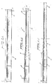
- Figs. 2A-2C show a first preferred embodiment of a shaft during various stages of fabrication.
- Fig. 3 shows a shaft of the present invention.
- Fig. 4 shows an embodiment of the present invention in use as a shaft for a golf club wood.
- Fig. 5 shows an embodiment of the present invention in use as a shaft for a golf club iron.
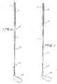
- Figs. 6A-6C show a second preferred embodiment of a shaft during various stages of fabrication.
- Fig. 7 shows a block diagram including the steps needed to perform a second preferred embodiment of the present invention.
- With reference now to the drawings, the various stages of forming a metal shaft are described.
- In the golf shaft manufacturing art, the outer diameter of a shaft intended for fabrication into a golf shaft is typically about .600". Apparently, the industry has found this diameter to be especially suited to providing any number of desired "flexes" and "flexpoints" in any variety of shafts. This diameter is not particularly suited, however, to providing a tip strength sufficient to render tip reinforcement unnecessary. It is generally estimated that a tip strength of at least 21 lbs. is required to prevent the tip of a golf shaft from excessively bending during play wherein tip strength is defined as the weight necessary to cause permanent deformation in the shaft when hung about 20 inches from the tip area.
- In contrast, in the preferred embodiments of the present invention, the outer diameter of a shaft intended for fabrication into a golf shaft is greater than .600". By virtue of this greater diameter, enough material is available to fabricate a shaft by conventional drawing and swaging methods that has a tip strength sufficient, i.e., greater than 21 lbs., to render unnecessary any additional reinforcement and that still has the desired "flexes" and "flexpoints".
- Referring to Fig. 1 and Figs. 2A-2C, a first preferred embodiment of the present invention is shown. A
shaft 10, made from titanium alloy and intended for use as a golf shaft, is provided having a substantiallyconstant wall thickness 20 and a substantially constantouter diameter 21 over itsentire length 2. Theouter diameter 21 is preferably about .665", thewall thickness 20 is preferably about .020" andlength 2 is preferably about 35 inches. - In the first step A of Fig. 1, one
end 12 ofshaft 10 is subjected to a conventional rotary swaging operation to form arear portion 60, afront portion 62 and an interconnectingportion 61 onshaft 10 as shown in Fig. 2B. Interconnectingportion 61 interconnects therear portion 60 to thefront portion 62. Due to the swaging, the outer diameter of the of the oneend 12 ofshaft 10 is decreased toouter diameter 29 and the wall thickness at oneend 12 ofshaft 10 is increased to athickness 22. The interconnectingportion 61 and thefront portion 62 extend alength 23 at oneend 12 ofshaft 10. Preferably, the reducedouter diameter 29 is about .450", the increasedthickness 22 is about .030" andlength 23 is about 7". - The resulting
front portion 62 serves at least two purposes. First, a clamping surface is provided to which a drawing tool can be attached for performing draw passes as discussed below. Second, the shaft now has a portion that is strengthened with respect to the remainder of the shaft due to the increased wall thickness. The increased wall thickness is highly desirable in certain uses for shafts, e.g. use in a golf club. - In step B of the first preferred embodiment of Fig. 1, a drawing tool (not shown) is clamped to the
front portion 62 of the shaft in a conventional manner and sink drawing is performed on therear portion 60 of the metal shaft adjacent the interconnectingportion 61. The sink drawing step includes at least one draw pass and reduces the initialouter diameter 21 of therear portion 60 of themetal shaft 10 to a smallerouter diameter 26 and increases the length of therear portion 60 of the metal shaft to an increasedlength 4 of the shaft as shown in Fig. 2C. Preferably, the smallerouter diameter 26 will be about .593" and the increasedlength 4 will be about 33.75". The smallerouter diameter 26 may be increased to a typically desired outer diameter of about .600" in a heat treatment process at the conclusion of all metal working. - Since the
outer diameter 21 is reduced through a sink drawing operation, i.e., drawing without an internal mandrel, the wall thickness of the rear portion of the shaft remains substantially the same as it was before drawing. The drawing operation will, however, increase the length of the shaft beyond its initial length due to the cold flow of the metal. - In step C of the first preferred embodiment of Fig. 1, the
metal shaft 10 is again subjected to a conventional rotary swaging operation, this time performed on a region including thefront portion 62, the interconnectingportion 61 and an adjacent segment of therear portion 60. Referring to Fig. 3, the swaging forms asmooth taper 98 on the interconnectingportion 61 overlength 93 and blends thetaper 98 with the front portion of theshaft 62. The swaging also reduces theouter diameter 29 onfront portion 62 to the final outer diameter 99 while increasingthickness 22 on thefront portion 62 to afinal thickness 94. The rotary swaging operation may require one to three passes and generally will be performed using long swaging dies as are known in the art. Preferably, thelength 93 of thetaper 98 of the interconnectingportion 61 is around 10.0" which would require one or two swaging operations using conventional 12"-15" swaging dies. The final outer diameter 99 of thefront portion 62 is preferably about .370". - After rotary swaging, a segment (not shown) of the
front portion 62 of the shaft that has served as a clamping surface for the drawing tool is cut off. The forces exerted on the metal on that segment will have caused scuffing and pitting thus rendering the surface unusable. It should be noted that only that segment effected by the clamped tool is removed and not the entire tip portion. Thus, afront portion 62 ofwall thickness 94 remains at the end of the shaft. - The
shaft 10 resulting from the method of the present invention has a wall of substantiallyconstant thickness 90 along length 91 of therear portion 60 of the shaft, a wall of increasing, tapered thickness 92 over the interconnectingportion 61 of theshaft 93, and a wall increasing to amaximum thickness 94 at thefront portion 62 of the shaft. Preferably, for a golf club shaft of titanium alloy, theconstant thickness 90 of the rear portion is about .020" over length 91 of about 20.75", the tapered thickness 92 progresses to about .032" over the interconnecting portion of theshaft 61 for alength 93 of about 10" and the maximum thickness increases from about .032" to .039" over a length 95 of about 9.25" at the front portion 96. For alength 97 of about 7.0" at the front portion 96, themaximum wall thickness 94 is substantially constant at about .039". The resulting titanium alloy golf club shaft of the preferred embodiment has an overall length of about 40" and a tip strength of about 23 lbs. - It should be noted that as a final step, the shaft may undergo as heat treatment process wherein one of the results is a growth in the outer diameter of the shaft. In a golf shaft of titanium alloy wherein the outer diameter after drawing is .593", the outer diameter after heat treatment will have increased to about .600" which is the industry standard for finished golf shafts.
- The metal that is particularly suited for this method of making a golf shaft is seamless titanium or titanium alloy (e.g., Ti-3A1-2.5V) tubing although other metal alloys are also acceptable. Welded tubing is not recommended since the weld could crack during swaging.
- This method is particularly adapted for making club irons or club woods as is shown in Figs. 4 and 5. The golf club includes a
handle portion shank portion striking portion handle portion handle portion shank portion shank portion striking portion - Referring now to Figs. 6A-6D and Fig. 7, a second preferred embodiment of the present invention will be described.
- As with the first embodiment, a shaft made from titanium alloy and intended for use as a golf shaft is provided, however, the
outer diameter 21 is preferably .625" instead of .665" and thewall thickness 20 is preferably about .025" instead of .020". - Yet, notwithstanding the use of tube stock of a smaller
outer diameter 21 than that described in the first embodiment, theouter diameter 21 remains greater than .600". Consequently, enough material remains available to form a shaft by conventional drawing and swaging methods having a tip strength sufficient to render unnecessary any additional reinforcement and, further, having the desired "flexes" and "flexpoints". - With reference to Fig. 6B and Fig. 7, step A, it is shown that
shaft 10 is subjected to the same rotary swaging operation of the first preferred embodiment shown in Fig. 2B and Fig. 1, step A and described previously. The swaging forms arear portion 60, afront portion 62 and an interconnectingportion 61. Theouter diameter 21 at oneend 12 ofshaft 10 is decreased toouter diameter 29 and thewall thickness 20 is increased to athickness 22. The interconnectingportion 61 and thefront portion 62 extend alength 23 at oneend 12 of theshaft 10. In the second embodiment, the reducedouter diameter 29 is preferably about .450 ", the increasedthickness 22 is preferably about .030 " andlength 23 is preferably about 6.25". - In the next step of the second preferred embodiment (see Figs. 6C-6D and Fig. 7, step B), instead of performing a sink drawing operation as with the first embodiment, a mandrel drawing operation is performed. A hardened steel mandrel 70 is inserted into
shaft 10 as shown in Fig. 6C and the drawing tool (not shown) is clamped to the front portion 64 of the shaft in a conventional manner. Conventional mandrel drawing is then performed on therear portion 60 of the metal shaft adjacent the interconnectingportion 61. - Since mandrel 70 travels with the
shaft 10 during mandrel drawing and, therefore, remains inside ofshaft 10 after mandrel drawing, the mandrel must be removed to allow further forming operations. Consequently, included in the second step of the second preferred embodiment of Fig. 7, step B is an operation whereinshaft 10 with mandrel 70 within, is subjected to a "derodding" process which involves passingshaft 10 and mandrel 70 through a double roll to "reel" theshaft 60 from the mandrel 70. This process is well known in the art. - The mandrel drawing step includes at least one draw pass and, as shown in Fig. 6D, reduces the original
outer diameter 21 of the shaft to a smallerouter diameter 26 while increasing the length of therear portion 60 to an increasedlength 4. In addition,initial wall thickness 20 is decreased to a reducedthickness 74. In the second preferred embodiment, the smallerouter diameter 26 will be about .593", the increasedlength 4 will be about 33.75" and the reducedwall thickness 74 will be about .020". The smallerouter diameter 26 may be increased to the typically desired outer diameter of about .600 inches in a heat treatment process at the conclusion of all metal working. - After the derodding operation of step B (Fig. 7) is completed, the metal shaft is subjected to a rotary swaging operation in as shown in Fig. 7, step C. Step C of Fig. 7 is the same swaging operation of step C, Fig. 2 of the first preferred embodiment described previously and provides the same shaft as shown in Fig. 3, also discussed previously.
- The method of the second embodiment of the present invention may be desired over the first embodiment if the dimensions of the metal tube stock that is intended for fabrication are nearer the preferred values of the second embodiment than those of the first embodiment.
- The principles, preferred embodiment and mode of operation of the present invention have been described in the foregoing specification. However, the invention which is intended to be protected is not to be construed as limited to the particular embodiment disclosed. The embodiment is to be regarded as illustrative rather than restrictive. Variations and changes may be made by others without departing from the spirit of the present invention. Accordingly, it is expressly intended that all such variations and changes which fall within the spirit and scope of the present invention as defined in claims be embraced thereby.
Claims (14)
providing a metal shaft having a first outer diameter and a first shaft wall thickness,
rotary swaging an end of said metal shaft to form a shaft front portion, a shaft rear portion and an interconnecting portion that interconnects said front and rear portions, said front portion having a second outer diameter smaller than said first outer diameter and a first front portion wall thickness larger than said first shaft wall thickness,
drawing said rear portion of said metal shaft to a third outer diameter smaller than said first outer diameter and larger than said second outer diameter,
rotary swaging a region including said front portion, said interconnecting portion and an adjacent segment of said rear portion such that said front end portion has a fourth outer diameter smaller than said second outer diameter and a second front portion wall thickness greater than said first front portion wall thickness and such that said interconnecting portion has a smooth taper that narrows from said third outer diameter to said fourth outer diameter.
a rear portion having a first outer diameter and a substantially constant first wall thickness,
a front portion having a second outer diameter smaller than said first outer diameter and a second wall thickness larger than said first wall thickness and substantially constant over a length of said front portion,
an interconnecting portion interconnecting said rear portion with said front portion, said interconnecting portion having a smoothly decreasing outer diameter from said rear portion to said front portion to form a taper, said interconnecting portion having a smoothly increasing wall thickness along said taper from said first wall thickness to a maximum interconnecting portion wall thickness, said maximum interconnecting portion wall thickness being smaller than said second wall thickness of said front portion.
Applications Claiming Priority (2)
| Application Number | Priority Date | Filing Date | Title |
|---|---|---|---|
| US341804 | 1989-04-24 | ||
| US07/341,804 US5074555A (en) | 1989-04-24 | 1989-04-24 | Tapered wall shaft with reinforced tip |
Publications (3)
| Publication Number | Publication Date |
|---|---|
| EP0395603A2 true EP0395603A2 (en) | 1990-10-31 |
| EP0395603A3 EP0395603A3 (en) | 1991-01-16 |
| EP0395603B1 EP0395603B1 (en) | 1993-08-11 |
Family
ID=23339104
Family Applications (1)
| Application Number | Title | Priority Date | Filing Date |
|---|---|---|---|
| EP90850068A Expired - Lifetime EP0395603B1 (en) | 1989-04-24 | 1990-02-15 | A tapered wall shaft with reinforced tip and method for its manufacture |
Country Status (4)
| Country | Link |
|---|---|
| US (1) | US5074555A (en) |
| EP (1) | EP0395603B1 (en) |
| JP (1) | JP2774157B2 (en) |
| DE (1) | DE69002678D1 (en) |
Families Citing this family (22)
| Publication number | Priority date | Publication date | Assignee | Title |
|---|---|---|---|---|
| US5257807A (en) * | 1992-06-01 | 1993-11-02 | Baumann Peter E | Golf club putter |
| TW361279U (en) * | 1995-01-31 | 1999-06-11 | Wilson Sporting Goods Co Ltd | Shaft for a golf club, set of golf clubs and method of selecting shafts |
| US5665010A (en) * | 1996-02-07 | 1997-09-09 | Advanced Retrofit Components Associated Leader (In) Golf, Inc. | Composite golf club shaft |
| US5989133A (en) * | 1996-05-03 | 1999-11-23 | True Temper Sports, Inc. | Golf club and shaft therefor and method of making same |
| US5857921A (en) * | 1996-05-24 | 1999-01-12 | Fm Precision Golf Manufacturing Corp. | Golf club shafts |
| US6117021A (en) | 1996-06-28 | 2000-09-12 | Cobra Golf, Incorporated | Golf club shaft |
| USD418566S (en) * | 1997-07-08 | 2000-01-04 | Cobra Golf Incorporated | Lower section of a shaft adapted for use in a golf club shaft |
| US5935017A (en) * | 1996-06-28 | 1999-08-10 | Cobra Golf Incorporated | Golf club shaft |
| US6146291A (en) * | 1997-08-16 | 2000-11-14 | Nydigger; James D. | Baseball bat having a tunable shaft |
| US6588459B2 (en) * | 1999-12-03 | 2003-07-08 | Shelby Enterprises, Inc. | Fuel tank filler neck and method of manufacturing same |
| JP3943390B2 (en) * | 2001-12-27 | 2007-07-11 | テルモ株式会社 | Metal tubular body and manufacturing method thereof |
| JP4394864B2 (en) * | 2002-05-07 | 2010-01-06 | テルモ株式会社 | Metal tubular body and manufacturing method thereof |
| US6735998B2 (en) * | 2002-10-04 | 2004-05-18 | George A. Mitchell Company | Method of making metal ball bats |
| DE20302615U1 (en) * | 2003-02-17 | 2004-07-15 | Tower Automotive Gmbh & Co. Kg | Hollow molded part with a closed cross-section and a reinforcement |
| US20050028341A1 (en) * | 2003-07-01 | 2005-02-10 | Durand Robert D. | Method of manufacturing a combined driveshaft tube and yoke assembly |
| US7048019B2 (en) * | 2003-09-30 | 2006-05-23 | Shelby Enterprises, Inc. | Fuel filler tube assembly and manufacturing method |
| US20050130773A1 (en) * | 2003-12-12 | 2005-06-16 | Hayden Mark X. | Sports shaft |
| CN100540168C (en) * | 2004-03-22 | 2009-09-16 | 乔治·A·米切尔公司 | Make the method for metal bat |
| DE112006003129A5 (en) * | 2005-09-13 | 2008-09-04 | Neumayer Tekfor Holding Gmbh | Hollow shaft and method of manufacture |
| US7328599B2 (en) * | 2006-02-02 | 2008-02-12 | Thu Van Nguyen | Method and apparatus for making metal ball bats |
| US8388473B2 (en) * | 2008-05-20 | 2013-03-05 | Easton Technical Products, Inc. | Arrow shaft with transition portion |
| DE102011007082A1 (en) * | 2011-04-08 | 2012-10-11 | Bos Gmbh & Co. Kg | Winding shaft of a roller blind system and roller blind system with winding shaft |
Citations (4)
| Publication number | Priority date | Publication date | Assignee | Title |
|---|---|---|---|---|
| US470178A (en) * | 1892-03-08 | Fishing-reel | ||
| US2095563A (en) * | 1934-10-25 | 1937-10-12 | American Fork & Hoe Co | Method of making golf club shafts |
| US3691625A (en) * | 1971-03-19 | 1972-09-19 | Reynolds Metals Co | Method of making ball bat metal body system |
| US4722216A (en) * | 1982-02-08 | 1988-02-02 | Grotnes Metalforming Systems, Inc. | Radial forging method |
Family Cites Families (37)
| Publication number | Priority date | Publication date | Assignee | Title |
|---|---|---|---|---|
| US391994A (en) * | 1888-10-30 | Wilhelm von flotow and hermann leidig | ||
| US601966A (en) * | 1898-04-05 | Manufacture of seamless drawn tubes | ||
| GB191330050A (en) * | 1913-12-31 | 1914-10-08 | Robert Goodman Roberts | An Improved Knee Grip for Strengthening the Knee for use in Playing Football and Games of a like Nature. |
| US1162960A (en) * | 1915-01-02 | 1915-12-07 | Vincent S Whyland | Process for reducing the diameter of wire. |
| US1778181A (en) * | 1924-06-24 | 1930-10-14 | Louis H Brinkman | Apparatus for forming tapered tubes |
| US1573708A (en) * | 1924-11-18 | 1926-02-16 | Union Hardware Company | Manufacture of golf-club shafts |
| US1696697A (en) * | 1926-02-20 | 1928-12-25 | William H Sommer | Apparatus for pointing wires |
| US1713812A (en) * | 1926-12-13 | 1929-05-21 | George E Barnhart | Method of making golf-club shafts |
| US1904146A (en) * | 1929-09-09 | 1933-04-18 | Western Electric Co | Wire drawing apparatus |
| GB332486A (en) * | 1929-10-26 | 1930-07-24 | Accles & Pollock Ltd | Improvements relating to tubular metallic shafts for golf clubs and their manufacture |
| US2001643A (en) * | 1930-10-03 | 1935-05-14 | American Fork & Hoe Co | Method of forming golf shafts and the like |
| US1962804A (en) * | 1930-10-03 | 1934-06-12 | American Fork & Hoe Co | Method of making golf clubs |
| US1983074A (en) * | 1931-06-11 | 1934-12-04 | American Fork & Hoe Co | Method of making golf club shafts |
| US1979430A (en) * | 1932-03-19 | 1934-11-06 | American Fork & Hoe Co | Method of forming shafts for golf clubs |
| US2066962A (en) * | 1934-04-16 | 1937-01-05 | Cross Lloyd | Shaft for golf clubs or the like |
| GB470178A (en) * | 1935-11-05 | 1937-08-05 | Norman Pearl Vickery | Golf clubs |
| US2100307A (en) * | 1936-02-20 | 1937-11-23 | Wiley W Mcminn | Hollow metal shaft and manufacture of same |
| US2240456A (en) * | 1939-10-06 | 1941-04-29 | Republic Steel Corp | Apparatus for producing tubular articles having varying wall thickness |
| US2950811A (en) * | 1951-06-05 | 1960-08-30 | Kreidler Alfred | Die guide and work-straightening device |
| AT256007B (en) * | 1963-11-21 | 1967-08-10 | Kieserling & Albrecht | Device for attaching folding rods to pipe ends, in particular to thin-walled pipes |
| US3479030A (en) * | 1967-01-26 | 1969-11-18 | Anthony Merola | Hollow,metal ball bat |
| US3570297A (en) * | 1968-09-19 | 1971-03-16 | Raymond A Matthews | Die and method for drawing metal tubes |
| GB1246539A (en) * | 1969-03-04 | 1971-09-15 | Ben Sayers Ltd | Improvements in or relating to golf clubs |
| DE2131874C3 (en) * | 1971-06-26 | 1984-07-19 | Benteler-Werke Ag, 4794 Schloss Neuhaus | Device for reducing pipe strings |
| US3854316A (en) * | 1971-09-13 | 1974-12-17 | Aluminum Co Of America | Method of making a hollow metal bat with a uniform wall thickness |
| US3841130A (en) * | 1973-11-20 | 1974-10-15 | Reynolds Metals Co | Ball bat system |
| US3969155A (en) * | 1975-04-08 | 1976-07-13 | Kawecki Berylco Industries, Inc. | Production of tapered titanium alloy tube |
| US4169595A (en) * | 1977-01-19 | 1979-10-02 | Brunswick Corporation | Light weight golf club shaft |
| JPS5816874B2 (en) * | 1977-07-12 | 1983-04-02 | 田辺製薬株式会社 | Purification method of urokinase |
| US4157654A (en) * | 1978-01-03 | 1979-06-12 | The Babcock & Wilcox Company | Tube forming process |
| US4298155A (en) * | 1979-08-01 | 1981-11-03 | Rockwell International Corporation | Method for making an axle spindle |
| JPS6011580B2 (en) * | 1982-01-26 | 1985-03-27 | 桂一郎 吉田 | Swaging machine for hot processing |
| JPS5910436A (en) * | 1982-07-09 | 1984-01-19 | Keiichiro Yoshida | Method and device for swaging long tapered metallic pipe |
| US4625537A (en) * | 1982-12-06 | 1986-12-02 | Grumman Aerospace Corporation | Localized boss thickening by cold swaging |
| US4512069A (en) * | 1983-02-04 | 1985-04-23 | Motoren-Und Turbinen-Union Munchen Gmbh | Method of manufacturing hollow flow profiles |
| JPS6114035A (en) * | 1984-06-28 | 1986-01-22 | Hisashi Oki | Manufacture of steering shaft |
| US4616500A (en) * | 1985-02-25 | 1986-10-14 | George A. Mitchell Company | Method for producing tubing of varying wall thickness |
-
1989
- 1989-04-24 US US07/341,804 patent/US5074555A/en not_active Expired - Fee Related
- 1989-09-11 JP JP1233060A patent/JP2774157B2/en not_active Expired - Lifetime
-
1990
- 1990-02-15 EP EP90850068A patent/EP0395603B1/en not_active Expired - Lifetime
- 1990-02-15 DE DE9090850068T patent/DE69002678D1/en not_active Expired - Lifetime
Patent Citations (4)
| Publication number | Priority date | Publication date | Assignee | Title |
|---|---|---|---|---|
| US470178A (en) * | 1892-03-08 | Fishing-reel | ||
| US2095563A (en) * | 1934-10-25 | 1937-10-12 | American Fork & Hoe Co | Method of making golf club shafts |
| US3691625A (en) * | 1971-03-19 | 1972-09-19 | Reynolds Metals Co | Method of making ball bat metal body system |
| US4722216A (en) * | 1982-02-08 | 1988-02-02 | Grotnes Metalforming Systems, Inc. | Radial forging method |
Also Published As
| Publication number | Publication date |
|---|---|
| JP2774157B2 (en) | 1998-07-09 |
| EP0395603A3 (en) | 1991-01-16 |
| US5074555A (en) | 1991-12-24 |
| DE69002678D1 (en) | 1993-09-16 |
| EP0395603B1 (en) | 1993-08-11 |
| JPH02295575A (en) | 1990-12-06 |
Similar Documents
| Publication | Publication Date | Title |
|---|---|---|
| US5074555A (en) | Tapered wall shaft with reinforced tip | |
| EP0370978B1 (en) | Constant wall shaft with reinforced tip | |
| AU674399B2 (en) | Composite iron golf club | |
| US7584531B2 (en) | Method of manufacturing a golf club head with a variable thickness face | |
| JP4398880B2 (en) | Wood type golf club head | |
| US7438649B2 (en) | Golf club head | |
| US7255652B2 (en) | Lightweight, durable golf club shafts | |
| US20030036442A1 (en) | Golf club head having a high coefficient of restitution and method of making it | |
| US20040082404A1 (en) | Golf club face plate and method of manufacture | |
| US5792007A (en) | Golf club and club shaft constructions | |
| JPH08299511A (en) | Shaft for golf club | |
| WO1998007476A9 (en) | Golf club and club shaft constructions | |
| JPS605311B2 (en) | Manufacturing method of metal body for ball butt | |
| JP2599634B2 (en) | Golf club set | |
| US5857921A (en) | Golf club shafts | |
| JP2004167115A (en) | Golf club head | |
| JP2002000777A (en) | Golf club head | |
| JP4456241B2 (en) | Manufacturing method of golf club head | |
| JP2004057645A (en) | Golf club head | |
| US20090247317A1 (en) | Golf club and manufacturing method thereof | |
| US7118491B2 (en) | Rado's cylindrical golf club heads and multifaceted hand grips | |
| JP2002000773A (en) | Metal wood head | |
| JP4285838B2 (en) | Metal golf club head | |
| US20020072439A1 (en) | Ball bat with thinner handle than barrell | |
| JP3009833B2 (en) | Metal wood head and method of manufacturing the same |
Legal Events
| Date | Code | Title | Description |
|---|---|---|---|
| PUAI | Public reference made under article 153(3) epc to a published international application that has entered the european phase |
Free format text: ORIGINAL CODE: 0009012 |
|
| AK | Designated contracting states |
Kind code of ref document: A2 Designated state(s): BE CH DE ES FR GB IT LI NL SE |
|
| PUAL | Search report despatched |
Free format text: ORIGINAL CODE: 0009013 |
|
| AK | Designated contracting states |
Kind code of ref document: A3 Designated state(s): BE CH DE ES FR GB IT LI NL SE |
|
| 17P | Request for examination filed |
Effective date: 19910205 |
|
| 17Q | First examination report despatched |
Effective date: 19920724 |
|
| GRAA | (expected) grant |
Free format text: ORIGINAL CODE: 0009210 |
|
| AK | Designated contracting states |
Kind code of ref document: B1 Designated state(s): BE CH DE ES FR GB IT LI NL SE |
|
| PG25 | Lapsed in a contracting state [announced via postgrant information from national office to epo] |
Ref country code: IT Free format text: LAPSE BECAUSE OF FAILURE TO SUBMIT A TRANSLATION OF THE DESCRIPTION OR TO PAY THE FEE WITHIN THE PRE;WARNING: LAPSES OF ITALIAN PATENTS WITH EFFECTIVE DATE BEFORE 2007 MAY HAVE OCCURRED AT ANY TIME BEFORE 2007. THE CORRECT EFFECTIVE DATE MAY BE DIFFERENT FROM THE ONE RECORDED.SCRIBED TIME-LIMIT Effective date: 19930811 Ref country code: NL Effective date: 19930811 Ref country code: ES Free format text: THE PATENT HAS BEEN ANNULLED BY A DECISION OF A NATIONAL AUTHORITY Effective date: 19930811 Ref country code: DE Effective date: 19930811 Ref country code: LI Effective date: 19930811 Ref country code: BE Effective date: 19930811 Ref country code: CH Effective date: 19930811 Ref country code: SE Effective date: 19930811 |
|
| REF | Corresponds to: |
Ref document number: 69002678 Country of ref document: DE Date of ref document: 19930916 |
|
| REG | Reference to a national code |
Ref country code: CH Ref legal event code: PL |
|
| ET | Fr: translation filed | ||
| NLV1 | Nl: lapsed or annulled due to failure to fulfill the requirements of art. 29p and 29m of the patents act | ||
| PG25 | Lapsed in a contracting state [announced via postgrant information from national office to epo] |
Ref country code: GB Effective date: 19940215 |
|
| PLBE | No opposition filed within time limit |
Free format text: ORIGINAL CODE: 0009261 |
|
| STAA | Information on the status of an ep patent application or granted ep patent |
Free format text: STATUS: NO OPPOSITION FILED WITHIN TIME LIMIT |
|
| 26N | No opposition filed | ||
| GBPC | Gb: european patent ceased through non-payment of renewal fee |
Effective date: 19940215 |
|
| PGFP | Annual fee paid to national office [announced via postgrant information from national office to epo] |
Ref country code: FR Payment date: 19980210 Year of fee payment: 9 |
|
| PG25 | Lapsed in a contracting state [announced via postgrant information from national office to epo] |
Ref country code: FR Free format text: LAPSE BECAUSE OF NON-PAYMENT OF DUE FEES Effective date: 19991029 |
|
| REG | Reference to a national code |
Ref country code: FR Ref legal event code: ST |