EP0397794B1 - Device for intubation of percutaneous endoscopic ostomy - Google Patents
Device for intubation of percutaneous endoscopic ostomy Download PDFInfo
- Publication number
- EP0397794B1 EP0397794B1 EP89902711A EP89902711A EP0397794B1 EP 0397794 B1 EP0397794 B1 EP 0397794B1 EP 89902711 A EP89902711 A EP 89902711A EP 89902711 A EP89902711 A EP 89902711A EP 0397794 B1 EP0397794 B1 EP 0397794B1
- Authority
- EP
- European Patent Office
- Prior art keywords
- tube
- inflation lumen
- cuff
- lumen
- port
- Prior art date
- Legal status (The legal status is an assumption and is not a legal conclusion. Google has not performed a legal analysis and makes no representation as to the accuracy of the status listed.)
- Expired - Lifetime
Links
Images


Classifications
-
- A—HUMAN NECESSITIES
- A61—MEDICAL OR VETERINARY SCIENCE; HYGIENE
- A61J—CONTAINERS SPECIALLY ADAPTED FOR MEDICAL OR PHARMACEUTICAL PURPOSES; DEVICES OR METHODS SPECIALLY ADAPTED FOR BRINGING PHARMACEUTICAL PRODUCTS INTO PARTICULAR PHYSICAL OR ADMINISTERING FORMS; DEVICES FOR ADMINISTERING FOOD OR MEDICINES ORALLY; BABY COMFORTERS; DEVICES FOR RECEIVING SPITTLE
- A61J15/00—Feeding-tubes for therapeutic purposes
- A61J15/0015—Gastrostomy feeding-tubes
- A61J15/0019—Gastrostomy feeding-tubes inserted by using a pull-wire
-
- A—HUMAN NECESSITIES
- A61—MEDICAL OR VETERINARY SCIENCE; HYGIENE
- A61J—CONTAINERS SPECIALLY ADAPTED FOR MEDICAL OR PHARMACEUTICAL PURPOSES; DEVICES OR METHODS SPECIALLY ADAPTED FOR BRINGING PHARMACEUTICAL PRODUCTS INTO PARTICULAR PHYSICAL OR ADMINISTERING FORMS; DEVICES FOR ADMINISTERING FOOD OR MEDICINES ORALLY; BABY COMFORTERS; DEVICES FOR RECEIVING SPITTLE
- A61J15/00—Feeding-tubes for therapeutic purposes
- A61J15/0026—Parts, details or accessories for feeding-tubes
- A61J15/003—Means for fixing the tube inside the body, e.g. balloons, retaining means
- A61J15/0034—Retainers adjacent to a body opening to prevent that the tube slips through, e.g. bolsters
- A61J15/0038—Retainers adjacent to a body opening to prevent that the tube slips through, e.g. bolsters expandable, e.g. umbrella type
- A61J15/0042—Retainers adjacent to a body opening to prevent that the tube slips through, e.g. bolsters expandable, e.g. umbrella type inflatable
-
- A—HUMAN NECESSITIES
- A61—MEDICAL OR VETERINARY SCIENCE; HYGIENE
- A61M—DEVICES FOR INTRODUCING MEDIA INTO, OR ONTO, THE BODY; DEVICES FOR TRANSDUCING BODY MEDIA OR FOR TAKING MEDIA FROM THE BODY; DEVICES FOR PRODUCING OR ENDING SLEEP OR STUPOR
- A61M25/00—Catheters; Hollow probes
- A61M25/10—Balloon catheters
-
- A—HUMAN NECESSITIES
- A61—MEDICAL OR VETERINARY SCIENCE; HYGIENE
- A61J—CONTAINERS SPECIALLY ADAPTED FOR MEDICAL OR PHARMACEUTICAL PURPOSES; DEVICES OR METHODS SPECIALLY ADAPTED FOR BRINGING PHARMACEUTICAL PRODUCTS INTO PARTICULAR PHYSICAL OR ADMINISTERING FORMS; DEVICES FOR ADMINISTERING FOOD OR MEDICINES ORALLY; BABY COMFORTERS; DEVICES FOR RECEIVING SPITTLE
- A61J15/00—Feeding-tubes for therapeutic purposes
- A61J15/0026—Parts, details or accessories for feeding-tubes
- A61J15/0073—Multi-lumen tubes
Landscapes
- Health & Medical Sciences (AREA)
- Life Sciences & Earth Sciences (AREA)
- Animal Behavior & Ethology (AREA)
- General Health & Medical Sciences (AREA)
- Public Health (AREA)
- Veterinary Medicine (AREA)
- Heart & Thoracic Surgery (AREA)
- Child & Adolescent Psychology (AREA)
- Gastroenterology & Hepatology (AREA)
- Biophysics (AREA)
- Pulmonology (AREA)
- Engineering & Computer Science (AREA)
- Anesthesiology (AREA)
- Biomedical Technology (AREA)
- Hematology (AREA)
- Media Introduction/Drainage Providing Device (AREA)
Abstract
Description
- The present invention relates to a device for intubating an ostomy such as a gastronomy formed by a percutaneous endoscopic technique.
- Such devices are described in e.g. DE-U-8705 894. However, it is impossible to draw the device in a retrograde manner through the patient. Such drawing through the patient can be carried out by another device according to DE-A 3 444 909; However, this device is relatively complicated.
- It is an objective of the present invention to combine anchor means and retention means of such devices into a single and simple structure which does not create tissue necrosis within the patient body.
- The invention is characterized in claim 1 and preferred embodiment thereof are claimed in subclaims.
- The invention allows to easily and comfortably remove an anchoring and retention tip at the conclusion of enteral feeding therapy through the gastrostomy.
- Prior to the present invention, a need existed for a catheter specially designed for intubating a gastrostomy or an other ostomy formed by a percutaneous endoscopic technique having an enlarged retention member which is pliable and smoothly contoured for a more comfortable intubation, anchor means which more evenly distributes contact surrounding tissues thereby avoiding tissue necrosis, anchor means which remain abutted against tissue surrounding the ostomy without pulling free, and an anchor means and retention member which may be compressed or collapsed to facilitate removal of the tube externally through the gastrostomy itself upon completion of enteral feeding therapy.
- The device of the present inventions meets the foregoing described needs by employing a multi-lumen enteral feeding tube, preferably having at least a fluid delivery lumen and an inflation lumen. The tube includes a port near one end to dispose the inflation lumen to ambient air and an outlet at an other end to convey fluid from within the fluid lumen into the patient.
A retention member, preferably an inflatable cuff, is joined near the other end of the tube. - In the preferred embodiment of the present invention, the cuff is substantially filled with a resilient porous material for maintaining the walls of the cuff in a fully inflated position. The retention cuff is in communication with the inflation lumen and is inflatable and deflatable through the inflation lumen. The walls of the cuff are designed so that in a deflated state, the cuff assumes an edge-free, preferably rounded, outer configuration to facilitate a comfortable intubation of the device into the patient. Likewise, in a fully inflated state, the cuff assumes an outer configuration defining at least one generally flat surface to more diffusely contact and abut against the inner tissue surfaces surrounding the gastrostomy.
- Joined to the one end of the tube is an elongated tapered sleeve which encloses the one end of the tube. The tapered end of the sleeve carries, preferably, a suture loop for use in intubating the device.
- In all embodiments of the present invention, means are provided for sealing the inflation lumen. For example, in one embodiment, the sleeve includes a skirt portion which creates a circumferential airtight seal about the exterior of the tube to selectively seal the ambient air port. The skirt portion of the sleeve is air pressure responsive to permit escape of air from the inflation lumen through the port but preventing the ingress of air into the inflation lumen through the port.
- In an alternate embodiment, the ambient air port is sealed by a frangible plug member. The frangible plug member generally includes a stem frangibly connected to an enlarged gripping portion.
- The device of the present invention is utilized in intubating a gastrostomy formed by a percutaneous endoscopic technique by the following steps. First, prior to intubation of the device into a patient, the cuff is deflated by compressing it, thereby expelling air out of the inflation lumen through the port. In one embodiment, the skirt portion of the sleeve expands outwardly in response to the greater air pressure within the lumen to permit the escape of air out of the inflation lumen through the port. Upon fully deflating the retention cuff, the air pressure within the inflation lumen decreases relative to ambient air pressure such that the skirt portion contracts inwardly to seal the ambient air port thus preventing ingress of air into the inflation lumen.
- In the alternate embodiment, the ambient air port may be sealed by inserting the stem of the frangible plug member into the port. The stem is inserted into the inflation lumen to a point such that when the frangible connection between the stem portion is broken, the stem remains in the port to occlude the inflation lumen.
- Initial deflation of the retention cuff may be accomplished by manually squeezing the cuff. However, in one preferred embodiment, the present invention provides for initial deflation of the cuff through use of a circular deflation strap. The cuff is captivated within the deflation strap and the strap is then tightened thus deflating the cuff and maintaining it in a deflated position until the ambient art port is sealed. The deflation strap is particularly useful in the embodiment of the present invention wherein a frangible plug is utilized for initial sealing of the inflation lumen.
- Sealing of the ambient air port prevents re-inflation of the cuff. In a deflated state, the retention cuff assumes an edge free generally oval outer configuration.
- Upon deflating the cuff and sealing the ambient air port, the suture loop carried on the tapered end of the sleeve is tied to the one end of the suture which extends from the patient's mouth. The gastroenterologist then begins pulling on the other end of the suture extending externally from the gastrostomy to lead the device in a retrograde manner through the mouth, esophagus and ultimately into the stomach. The retrograde drawing of the device continues until the deflated cuff abuts against inner tissue surfaces surrounding the gastrostomy. Air is then externally introduced into the inflation lumen to re-inflate the retention cuff to change the outer configuration of the cuff to create a generally flat anchor surface.
- In the one method of practicing the present invention, re-inflation of the cuff may be achieved by severing the multi-lumen tube below the sleeve to remove the sleeve from the tube. This exposes the inflation lumen to ambient air resulting in re-inflation of the cuff. In the alternate method wherein a frangible plug has occluded the inflation lumen, the multi-lumen tube may be similarly severed below the plugged area of the inflation lumen.
- After re-inflation of the cuff, the inflation lumen should be sealed with a plug, such as another frangible plug member, or other device to prevent deflation of the retention cuff. Then, as is conventional, the severed end of the multi-lumen tube is secured at the exterior of the ostomy by means known in the art such as by tape or suture. This prevents the inflated cuff from dislodging from the tissue wall and to keep the cuff urged against the inner tissue surface surrounding the ostomy.
- A luer adaptor or other tube connecting device may be affixed to the severed end of.the tube to place the tube in fluid communication with an enteral nutritional fluid source.
- Other advantages and aspects of the invention will become apparent upon making reference to the specification, claims, and drawings to follow.
-
- FIG. 1 discloses in perspective view one embodiment of the present invention;
- FIG. 2 is a longitudinal section taken along line 2-2 in FIG. 1;
- FIG. 2A is a vertical section taken through
line 2A-2A of FIG. 2; - FIG. 3 is a fragmented detailed view of a portion of FIG. 2 disclosing outward flexing of the skirt portion of the elongated sleeve permitting an escape of air from within the inflation lumen;
- FIG. 3A is the same view of FIG. 3 disclosing an inward contraction of the skirt portion to seal the ambient air port of the inflation lumen;
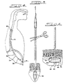
- FIG. 4 illustrates retrograde intubation of one embodiment of the device of the present invention;
- FIG. 5 illustrates severing a portion of the tube of the present invention to introduce air into the inflation lumen;
- FIG. 6 discloses a preferred outer configuration of a fully inflated retention cuff of the present invention;
- FIG. 7 is a longitudinal section disclosing an alternate embodiment of the present invention;
- FIG. 7A is the same view of FIG. 7 wherein a plug member having a frangible stem seals the inflation lumen;
- FIG. 8 is a side elevational view disclosing an embodiment of a frangible plug member;
- FIG. 9 is a plan view of an open and extended embodiment of an inflation strap; and,
- FIG. 10 is a detailed longitudinal section of a portion of a multi-lumen tube disclosing the frangible plug member of FIG. 8 occluding the inflation lumen.
- While this invention is susceptible of embodiment in many different forms, there is shown in the drawings and will herein be described in detail at least two embodiments of the invention. The present disclosure is to be considered as an exemplification of the principles of the invention and is not intended to limit the broad aspect of the invention to embodiment illustrated.
- Referring now to the drawings, FIG. 1 discloses one embodiment of
device 10 of the present invention comprised of a multi-lumen enteral feeding tube. As disclosed in FIG. 2 and best disclosed in FIG. 2A, feedingtube 12 includes at least aninflation lumen 14 and afluid delivery lumen 16.Lumens septum 18. As disclosed in FIG. 2, oneend 12A oftube 12 has at least oneambient air port 20 which, as will be disclosed later in greater detail, disposesinflation lumen 14 in communication with ambient air. At another end 12B oftube 12, the fluid outlet 22 (shown in phantom in FIG. 2) conveys fluid fromfluid lumen 16 into a patient. - Sealably secured to end 12A of
tube 12 is anenclosed sleeve 24, preferably having a tapered elongated conicalterminal end 26. The tapered conical outer configuration ofterminal end 26 permits atraumatic parting of esophageal and gastric tissues during the intubation process. As disclosed in FIGS. 1 and 2 disposed on theterminal end 26 ofsleeve 24 is asuture loop 28 which permitsdevice 10 to be tied to the end of the suture extending from the patient's mouth during the percutaneous endoscopic technique (not shown in the drawings). As disclosed in FIG. 2,suture loop 28 may preferably fully extend throughsleeve 24 through achannel 32 and be secured to end 12A oftube 12 by a fastening knot orother fastening device 34 secured to theseptum 18. - FIGS. 1 through 3A disclose one preferred embodiment of the present invention wherein, joined to
sleeve 24, is askirt portion 36 which circumferentially surroundsend 12A oftube 12 in such a manner to create an airtight seal betweenskirt portion 36 and outer surfaces ofend 12A.Skirt portion 36 is made from a highly pliable plastic or latex rubber so as to be air pressure responsive permitting selective sealing ofambient air port 20. Specifically,skirt portion 36 responds to greater air pressure withininflation lumen 14 to permit the escape of air out oflumen 14 throughport 20 However, when ambient air pressure exceeds the air pressure withinlumen 14, thenskirt portion 36 contracts inwardly to sealport 20 to prevent the further ingress of air intolumen 14. - FIGS. 3 and 3A disclose in greater detail the selective sealing or diaphragmatic action of
skirt portion 36. As disclosed in FIG. 3, when air pressure withininflation lumen 14 increases to exceed ambient air pressure,skirt 36 expands outwardly away from the walls oftube 12 to define acircumferential gap 38 which permits air to exitambient port 20 and escape from underskirt portion 36. As disclosed in FIG. 3A, when ambient air pressure exceeds the air pressure withininflation lumen 14,skirt portion 36 contracts circumferentially abouttube 12closing gap 38 and thereby forming an airtight seal abouttube 12 andport 20. - The selective sealing of
ambient port 20 allows for the controlled inflation and deflation of a retention/anchor member, which preferably is embodied as anannular cuff 40. As best disclosed in FIG. 2,retention cuff 40 is affixed to theother end 12B oftube 12.Retention cuff 40 is sealed and in gas communication withinflation lumen 14 through aterminal opening 42 intube 12. As shown in phantom in FIGS. 1 and 2,tube 12 passes throughcuff 40 so that, as disclosed in FIG. 6,fluid outlet 22 extends belowcuff 40. In the preferred embodiment of the present invention,cuff 40 is comprised of a distendableouter wall 40 which defines a cavity preferably substantially filled with a porousresilient foam material 46. As disclosed in FIG. 6,foam material 46 is cut in a configuration so that whencuff 40 is in a fully expanded position,foam material 46 maintainswalls 44 in expanded position. -
Retention cuff 40 is placed in a deflated state by compressing, preferably by squeezing,cuff 40 so that the air trapped withinwalls 44 andfoam material 46 is expelled upwardly into the inflation lumen and out ofport 20. Discontinuing such squeezing ofcuff 40 results in a decrease in air pressure withininflation lumen 14 so that ambient air pressure acts uponskirt 36 to sealport 20 in the manner described above. Such sealing ofport 20 prevents re-inflation ofretention cuff 40 and maintainscuff 40 in a deflated position. Re-inflation ofcuff 40 is achieved by introducing ambient air intoinflation lumen 14 by methods to be described below in greater detail. -
Cuff 40 combines in a single structure both the retention and anchoring functions achieved by prior art catheter mushroom-type tips and perpendicular rubber bumpers. However, unlike the prior art mushroom tip/bumper combination,cuff 40 in a deflated state, assumes an essentially edge-free, rounded configuration which facilitates intubation ofdevice 10.Cuff 40, in a deflated state, preferably assumes a oval or pill-shape as disclosed in FIGS. 1 and 2. In a fully inflated state,cuff 40 assumes a different configuration. Thewalls 44 ofcuff 40 are molded or pre-formed so that the outer configuration ofcuff 40 changes from a deflated state to a fully inflated state. For example,cuff 40 includes a fold orcrease line 48 which changes the outer configuration ofcuff 40 from deflation to full inflation. As disclosed in FIG. 6, upon full inflation ofcuff 40,fold line 48 defines a peripheral edge of a generally flat retention andanchor surface 50.Surface 50 is of a sufficient surface area to evenly distribute contact pressures on the tissue surrounding the gastrostomy to avoid the necrosis of tissue commonly encountered by use of prior art retention bumpers. Hence, a novel aspect of the present invention is that the retention cuff, in a deflated position, has an edge-free contour to facilitate a comfortable intubation, whereas, in a fully inflated state,retention cuff 40 assumes a different configuration to define an edged, flattened surface for anchoringtube 12 within the gastrostomy. - FIGS. 4 through 6 disclose the general method of using
device 10 in intubating an ostomy formed by a percutaneous endoscopic technique. As disclosed in FIG. 4, after the length of suture has been drawn out of a patient's mouth such that the free ends of the suture extend from both the patient's mouth and the gastrostomy, the suture is tied toloop 28 of the device of the present invention. The device of the present invention is then drawn downward through the mouth, esophagus and into the stomach in a retrograde manner. The pulling of the suture through the gastrostomy continues until the deflatedretention cuff 40 abuts against the inner tissue surfaces of the gastrostomy as disclosed in FIG. 5. To retain and anchor thefluid outlet end 12B oftube 12 within the gastrostomy,retention cuff 40 is re-inflated by introducing air into theinflation lumen 14 and then theinflation lumen 14 is sealed as disclosed below to prevent inadvertent deflation. As is conventional, the exposed portion oftube 12 is then secured near the external tissue surface of the ostomy to maintain the position of theretention cuff 40 against the inner tissue surrounding the ostomy, as disclosed in FIG. 6. The exposed portion may be secured by conventional means such as by tape or suture 51 thetube 12 to the external tissue. - In one preferred method of using the present invention, re-inflation of the
retention cuff 40 may be accomplished by severing, as disclosed in FIG. 5, completely through a portion oftube 12 external to the gastrostomy. Upon severing completely throughtube 12,inflation lumen 14 is exposed to ambient air thereby raising the air pressure withinlumen 14 to automatically inflatecuff 40. In some instances it may be necessary to assist the inflation operation by injecting air intoinflation lumen 14 through the insertion of the tip of an air-filled syringe intoinflation lumen 14. Upon full inflation ofretention cuff 40,inflation lumen 14 is sealed with a plug or other device to prevent deflation ofcuff 40, such asfrangible plug 60 of FIG. 8 which will be disclosed in more detail below. - With retention and anchoring of
device 10 complete, a luer adaptor or other tube connection means may be affixed to the severed end oftube 12 to jointube 12 to a source of enteral nutritional fluid. It should be noted that such adaptor or tube connection means may also function to sealinflation lumen 14. - FIGS. 7 through 10 disclose another preferred embodiment of the present invention. As best disclosed in FIGS. 7 and 7A a multi-lumen
enteral feeding tube 10 as previously disclosed is provided whereinskirt 36 is omitted or rendered non-functional. However, in this embodiment, taperedend 26 is nonetheless utilized to facilitate intubation. In this embodiment, ambient-air port 20 is exposed rather than being concealed underneathskirt 36. In this embodiment, initial sealing of theinflation lumen 14 is accomplished by occluding the lumen with a plug member of the type disclosed in FIG. 8 which is inserted into the lumen through ambient-air port 20. - As disclosed in FIG. 8,
frangible plug 60 generally comprises a solidcylindrical stem 62 and an enlarged grippingportion 64 on one end ofstem 62. A portion ofstem 62 is crimped or narrowed to define afrangible region 66. The diameter ofstem 62 is dimensioned to permit an interference fit with the inner diameter ofinflation lumen 14.Frangible region 66 is adapted to allow grippingportion 64 to be twisted or bent to break-offstem 62 allowing the gripping portion to be removed. - As disclosed in FIGS. 7 and 7A, prior to intubation,
retention cuff 40 is compressed. In this embodiment, however,inflation lumen 14 is occluded by insertingplug 60 into the inflation lumen while thecuff 40 is still compressed thus preventing premature re-inflation of the retention cuff. - FIG. 10 best discloses that the
frangible plug 60 is inserted throughambient port 20 to a position wherefrangible portion 66 is insideinflation lumen 14 so that when stem 62 is broken from grippingportion 64, stem 62 is totally enclosed withlumen 14 thus not presenting any protrusion which would cause damage during intubation. - In this embodiment,
retention cuff 40 may be compressed by squeezing the cuff in the palm off one hand while holdingtube 12 between the thumb and forefinger of the same hand leaving the other hand of the user free to grip the frangible plug for insertion while the cuff remains compressed. - After intubation, air may be introduced into the
retention cuff 40 in a manner similar to that disclosed above by cutting themulti-lumen tube 12 below the occluded area. As disclosed above the retention cuff may be maintained in the re-inflated position by the insertion of another frangible plug member into the exposed open end of theinflation lumen 14. -
Cuff 40 may also be compressed and maintained in a compressed state by anadjustable strap 70 such as disclosed in FIG. 9.Strap 70 is a generally flat flexible member including a widenedbody portion 72, an integral narrowedtongue portion 74 on one end of the body portion which has a plurality ofbarbs 78 on the its edges and aslot 76 at an opposite end of the body portion.Body portion 72 is dimensioned to engage on a substantial portion of the outer surface ofretention cuff 40.Tongue portion 74 is cooperatively dimensioned withslot 76 so that the tongue may be inserted into the slot and pulled therethrough withbarbs 78 engaging the edges of the slot to prevent retrograde movement of the tongue. - Thus, as disclosed in FIGS. 7 and 7A, prior to
intubation retention cuff 40 is captured withinstrap 70 and then thetongue 74 is pulled throughslot 76 to compress the cuff and maintain the cuff in the compressed state until the user can insertfrangible plug member 60 intoport 20 to seal theinflation lumen 14. Once the plug member is inserted,strap 70 can be removed by pulling or cutting the strap. - Utilization of the compression strap allows the user to more easily accomplish retaining the cuff in a compressed state until the lumen can be plugged. In certain instances, use of the compression strap may also provide a more aseptic means for compressing the retention cuff by avoiding contact of the cuff with the hands.
- While the specific embodiments have been illustrated and described, numerous modifications come to mind without significantly departing from the spirit of the invention and the scope of protection is only limited by the scope of the accompanying Claims.
Claims (5)
- Device for intubating an ostomy, such as a gastrostomy, formed by a percutaneous endoscopic technique, comprising:
a tube (12) having at least a fluid lumen (16) and an inflation lumen (14), the tube (12) having an air port (20) near one end (12A) to dispose the inflation lumen (14) to ambient air and a fluid outlet (22) convey fluid from within the fluid lumen (16) into the patient; a retention member (40) being joined near an other end (12 b) of the tube (12), the member being inflatable through the inflation lumen (14), the retention member (40) in a deflated state having a generally edge-free outer configuration to facilitate intubation, the retention member (40) in an inflated state defining at least one generally flat retention and anchoring surface;
means (36, 62) for sealing the ambient air port (20) of the tube (12);
wherein prior to intubation, the retention member (40) is compressed to deflate the member by expelling air out of the inflation lumen (14) through the port (20), the sealing means is used to seal the port (20) to prevent re-inflation of the retention member (40) and wherein air is introduced into the inflation lumen (14) to re-inflate the retention member (40) and anchor the device against the inner tissue surfaces of the ostomy,
characterized in
that a sleeve (24) is joined to and sealing the one end (12A) of the tube (12), the sleeve (24) having an edge-free outer configuration for gently parting gastroenteral tissues during intubation;
that said fluid outlet (22) is situated at said other end (12B) of said tube (12) the device is such, that in use, said one end (12A) of said tube (12) can be drawn through the patient in a retrograde manner until the deflated retention member (40) abuts against inner tissue surfaces of the ostomy, whereafter the sealing means (36; 62) are used to re-seal the inflation lumen (14) to prevent deflation of the retention member (40). - Device as claimed in claim 1 characterized in that said sealing means comprise a skirt portion (36) joined to the sleeve (24), the skirt portion (36) forming an air-tight seal about the circumference of the tube (12) and covering the ambient air port (20), the skirt portion (36) expanding outwardly in response to greater air pressure within the inflation lumen (14) to permit expulsion of air out of the port (20) and contracting inwardly in response to greater air pressures outside the inflation lumen (14) to seal the port (20).
- Device as claimed in claim 1 or 2 characterized in that said inflatable retention member includes a substantially foam filled annular cuff (40).
- Device as claimed in claim 3 characterized in that said annular cuff (40) has at least one generally flattened surface for abutment against the inner surfaces of the gastrostomy.
- Device as claimed in one of claim 1 to 4, characterized in that the terminal end of the sleeve (24) has a conical shape and a loop of suture is carried on said terminal end to draw the device in a retrograde manner through the esophagus and the ostomy.
Applications Claiming Priority (4)
| Application Number | Priority Date | Filing Date | Title |
|---|---|---|---|
| US144527 | 1988-01-15 | ||
| US07/144,527 US4795430A (en) | 1988-01-15 | 1988-01-15 | Device for intubation of percutaneous endoscopic ostomy |
| US07/291,115 US4900306A (en) | 1988-01-15 | 1988-12-28 | Device for intubation of percutaneous endoscopic ostomy |
| US291115 | 1994-08-16 |
Publications (2)
| Publication Number | Publication Date |
|---|---|
| EP0397794A1 EP0397794A1 (en) | 1990-11-22 |
| EP0397794B1 true EP0397794B1 (en) | 1993-05-12 |
Family
ID=26842082
Family Applications (1)
| Application Number | Title | Priority Date | Filing Date |
|---|---|---|---|
| EP89902711A Expired - Lifetime EP0397794B1 (en) | 1988-01-15 | 1988-12-30 | Device for intubation of percutaneous endoscopic ostomy |
Country Status (4)
| Country | Link |
|---|---|
| US (1) | US4900306A (en) |
| EP (1) | EP0397794B1 (en) |
| DE (1) | DE3881060T2 (en) |
| WO (1) | WO1989006529A1 (en) |
Families Citing this family (55)
| Publication number | Priority date | Publication date | Assignee | Title |
|---|---|---|---|---|
| US4981471A (en) * | 1988-01-15 | 1991-01-01 | Corpak, Inc. | Device for intubation of percutaneous endoscopic ostomy |
| US5125897A (en) * | 1990-04-27 | 1992-06-30 | Corpak, Inc. | Gastrostomy device with one-way valve and cuff pin |
| US5098396A (en) * | 1990-10-19 | 1992-03-24 | Taylor Ellis R | Valve for an intravascular catheter device |
| US5439444A (en) * | 1991-01-28 | 1995-08-08 | Corpak, Inc. | Pre-formed member for percutaneous catheter |
| US5308325A (en) * | 1991-01-28 | 1994-05-03 | Corpak, Inc. | Retention balloon for percutaneous catheter |
| US5112310A (en) * | 1991-02-06 | 1992-05-12 | Grobe James L | Apparatus and methods for percutaneous endoscopic gastrostomy |
| US5318530A (en) * | 1991-12-06 | 1994-06-07 | Bissel Medical Products, Inc. | Gastrointestinal tube with inflatable bolus |
| US5356391A (en) * | 1992-06-22 | 1994-10-18 | Medical Innovations Corp. | Flexible retainer flange for gastrostomy tube and the method of installing it |
| DE4236210C1 (en) * | 1992-10-27 | 1994-04-14 | Olympus Optical Europ | Tubular implant for use in percutaneous feeding |
| US5451212A (en) * | 1994-01-21 | 1995-09-19 | Corpak, Inc. | Bumper retention device |
| US5720734A (en) * | 1994-02-28 | 1998-02-24 | Wilson-Cook Medical, Inc. | Gastrostomy feeding ports |
| US5556385A (en) * | 1994-12-06 | 1996-09-17 | Corpak, Inc. | Improved percutaneous access device |
| US6066112A (en) * | 1996-01-11 | 2000-05-23 | Radius International Limited Partnership | Corporeal access tube assembly and method |
| US6077243A (en) * | 1996-01-11 | 2000-06-20 | C.R. Bard, Inc. | Retention balloon for a corporeal access tube assembly |
| DE69733010T2 (en) * | 1996-01-11 | 2006-02-16 | C.R. Bard, Inc. | TUBE UNIT FOR BODY ACCESS |
| US6036673A (en) * | 1996-01-11 | 2000-03-14 | C. R. Bard, Inc. | Bolster for corporeal access tube assembly |
| US5860952A (en) * | 1996-01-11 | 1999-01-19 | C. R. Bard, Inc. | Corporeal access tube assembly and method |
| US5913816A (en) * | 1997-10-31 | 1999-06-22 | Imagyn Medical Technologies, Inc. | Intubation device and method |
| US6322538B1 (en) | 1999-02-18 | 2001-11-27 | Scimed Life Systems, Inc. | Gastro-intestinal tube placement device |
| US6511474B1 (en) * | 2000-07-12 | 2003-01-28 | Corpak, Inc. | Bolus for non-occluding high flow enteral feeding tube |
| US6960199B2 (en) * | 2000-12-14 | 2005-11-01 | J&R Medical Devices, Inc. | Method for feeding with a tube |
| US6743207B2 (en) | 2001-04-19 | 2004-06-01 | Scimed Life Systems, Inc. | Apparatus and method for the insertion of a medical device |
| US6673058B2 (en) | 2001-06-20 | 2004-01-06 | Scimed Life Systems, Inc. | Temporary dilating tip for gastro-intestinal tubes |
| US7048722B2 (en) * | 2001-11-16 | 2006-05-23 | Radius International Limited Partnership | Catheter |
| AU2002364765B2 (en) | 2001-11-21 | 2005-03-03 | Boston Scientific Limited | Method for implanting a percutaneous/jejunostomy tube in a patient and access needle for use in said method |
| US20040158229A1 (en) * | 2002-01-24 | 2004-08-12 | Quinn David G. | Catheter assembly and method of catheter insertion |
| US6802836B2 (en) * | 2002-02-19 | 2004-10-12 | Scimed Life Systems, Inc. | Low profile adaptor for use with a medical catheter |
| US7507230B2 (en) * | 2002-02-19 | 2009-03-24 | Boston Scientific Scimed, Inc. | Medical catheter assembly including multi-piece connector |
| US20030225369A1 (en) * | 2002-05-31 | 2003-12-04 | Kimberly-Clark Worldwide, Inc. | Low profile transpyloric jejunostomy system |
| US20030225392A1 (en) * | 2002-05-31 | 2003-12-04 | Kimberly-Clark Worldwide, Inc. | Low profile transpyloric jejunostomy system and method to enable |
| US20030225393A1 (en) * | 2002-05-31 | 2003-12-04 | Kimberly-Clark Worldwide, Inc. | Low profile transpyloric jejunostomy system and method to enable |
| US20040054350A1 (en) * | 2002-09-17 | 2004-03-18 | Shaughnessy Michael C. | Enteral feeding unit having a reflux device and reflux method |
| ATE391524T1 (en) * | 2002-11-15 | 2008-04-15 | Radius Int Lp | CATHETER |
| US6997900B2 (en) * | 2002-12-09 | 2006-02-14 | Scimed Life Systems, Inc. | Connector for use with a medical catheter and medical catheter assembly |
| US20040116899A1 (en) * | 2002-12-16 | 2004-06-17 | Shaughnessy Michael C. | Bolus for non-occluding high flow enteral feeding tube |
| US7654980B2 (en) * | 2004-05-14 | 2010-02-02 | Boston Scientific Scimed, Inc. | Method for percutaneously implanting a medical catheter and medical catheter implanting assembly |
| US20060030818A1 (en) * | 2004-08-09 | 2006-02-09 | Mcvey Robert D | System and method for securing a medical access device |
| US7976518B2 (en) | 2005-01-13 | 2011-07-12 | Corpak Medsystems, Inc. | Tubing assembly and signal generator placement control device and method for use with catheter guidance systems |
| US7914497B2 (en) * | 2005-01-26 | 2011-03-29 | Radius International Limited Partnership | Catheter |
| US20070060898A1 (en) * | 2005-09-07 | 2007-03-15 | Shaughnessy Michael C | Enteral medical treatment assembly having a safeguard against erroneous connection with an intravascular treatment system |
| US8021338B2 (en) * | 2005-09-14 | 2011-09-20 | Boston Scientific Scimed, Inc. | Percutaneous endoscopic jejunostomy access needle |
| US7985205B2 (en) * | 2005-09-14 | 2011-07-26 | Boston Scientific Scimed, Inc. | Medical catheter external bolster having strain relief member |
| US7967786B2 (en) * | 2005-09-15 | 2011-06-28 | Boston Scientific Scimed, Inc. | Access needle well-suited for percutaneous implantation in a body lumen |
| US8172801B2 (en) * | 2005-09-15 | 2012-05-08 | Boston Scientific Scimed, Inc. | Method for positioning a catheter guide element in a patient and kit for use in said method |
| US8048062B2 (en) | 2005-12-30 | 2011-11-01 | Boston Scientific Scimed, Inc. | Catheter assembly and method for internally anchoring a catheter in a patient |
| US20070255222A1 (en) * | 2006-03-27 | 2007-11-01 | Changqing Li | Catheter assembly including internal bolster |
| US7547303B2 (en) * | 2006-08-03 | 2009-06-16 | Boston Scientific Scimed, Inc. | Catheter assembly including foldable internal bolster |
| US8157765B2 (en) | 2006-10-20 | 2012-04-17 | Boston Scientific Scimed, Inc. | Medical catheter assembly including a balloon bolster |
| WO2008121311A1 (en) * | 2007-03-29 | 2008-10-09 | Boston Scientific Scimed, Inc. | Catheter assembly including coiled internal bolster |
| JP2013537460A (en) * | 2010-08-17 | 2013-10-03 | セント・ジュード・メディカル,インコーポレイテッド | Medical implant delivery device tip |
| US9028441B2 (en) | 2011-09-08 | 2015-05-12 | Corpak Medsystems, Inc. | Apparatus and method used with guidance system for feeding and suctioning |
| US9386910B2 (en) | 2012-07-18 | 2016-07-12 | Apollo Endosurgery, Inc. | Endoscope overtube for insertion through a natural body orifice |
| WO2016205754A1 (en) | 2015-06-19 | 2016-12-22 | University Of Southern California | Compositions and methods for modified nutrient delivery |
| WO2016205701A1 (en) * | 2015-06-19 | 2016-12-22 | University Of Southern California | Enteral fast access tract platform system |
| WO2018187235A1 (en) * | 2017-04-03 | 2018-10-11 | John Langell | Low-profile videoscopic speculum with working port |
Citations (1)
| Publication number | Priority date | Publication date | Assignee | Title |
|---|---|---|---|---|
| EP0256546A2 (en) * | 1986-08-18 | 1988-02-24 | Frimberger, Erintrud | Device for placing a feeding tube in the stomach of a human being or of an animal |
Family Cites Families (15)
| Publication number | Priority date | Publication date | Assignee | Title |
|---|---|---|---|---|
| US3190291A (en) * | 1962-10-08 | 1965-06-22 | Frederic E B Foley | Self-inflating bag catheter |
| US3656485A (en) * | 1970-04-27 | 1972-04-18 | Jack R Robertson | Method of and apparatus for viewing the interior of the bladder through a suprapubic incision |
| US3640282A (en) * | 1970-08-06 | 1972-02-08 | Jack M Kamen | Tracheal tube with normally expanded balloon cuff |
| US3799173A (en) * | 1972-03-24 | 1974-03-26 | J Kamen | Tracheal tubes |
| US4141364A (en) * | 1977-03-18 | 1979-02-27 | Jorge Schultze | Expandable endotracheal or urethral tube |
| US4356824A (en) * | 1980-07-30 | 1982-11-02 | Vazquez Richard M | Multiple lumen gastrostomy tube |
| US4666433A (en) * | 1984-11-05 | 1987-05-19 | Medical Innovations Corporation | Gastrostomy feeding device |
| US4685901A (en) * | 1984-11-05 | 1987-08-11 | Medical Innovations Corporation | Gastro-jejunal feeding device |
| DE3444909A1 (en) * | 1984-12-08 | 1986-06-12 | Fresenius AG, 6380 Bad Homburg | Catheter for enteral nutrition, especially for intraduodenal administration, by gastrostomy |
| US4642092A (en) * | 1984-12-10 | 1987-02-10 | Gerald Moss | Gastrointestinal aspirating device with suction breakers |
| US4758219A (en) * | 1985-05-17 | 1988-07-19 | Microvasive, Inc. | Enteral feeding device |
| US4668225A (en) * | 1985-12-23 | 1987-05-26 | Superior Healthcare Group, Inc. | Gastrostomy tube and gastrostomy-jejunal feeding tube combination |
| JPH0796654B2 (en) * | 1986-08-20 | 1995-10-18 | 大日精化工業株式会社 | Pigment dispersion method |
| DE8705894U1 (en) * | 1987-04-23 | 1987-06-19 | Fresenius Ag, 6380 Bad Homburg, De | |
| US4795430A (en) * | 1988-01-15 | 1989-01-03 | Corpak, Inc. | Device for intubation of percutaneous endoscopic ostomy |
-
1988
- 1988-12-28 US US07/291,115 patent/US4900306A/en not_active Expired - Lifetime
- 1988-12-30 WO PCT/US1988/004709 patent/WO1989006529A1/en active IP Right Grant
- 1988-12-30 EP EP89902711A patent/EP0397794B1/en not_active Expired - Lifetime
- 1988-12-30 DE DE8989902711T patent/DE3881060T2/en not_active Expired - Fee Related
Patent Citations (1)
| Publication number | Priority date | Publication date | Assignee | Title |
|---|---|---|---|---|
| EP0256546A2 (en) * | 1986-08-18 | 1988-02-24 | Frimberger, Erintrud | Device for placing a feeding tube in the stomach of a human being or of an animal |
Also Published As
| Publication number | Publication date |
|---|---|
| US4900306A (en) | 1990-02-13 |
| WO1989006529A1 (en) | 1989-07-27 |
| DE3881060T2 (en) | 1993-08-19 |
| DE3881060D1 (en) | 1993-06-17 |
| EP0397794A1 (en) | 1990-11-22 |
Similar Documents
| Publication | Publication Date | Title |
|---|---|---|
| EP0397794B1 (en) | Device for intubation of percutaneous endoscopic ostomy | |
| US4795430A (en) | Device for intubation of percutaneous endoscopic ostomy | |
| US4981471A (en) | Device for intubation of percutaneous endoscopic ostomy | |
| US6027478A (en) | Nasal cavity drainage and stoppage system | |
| US4701163A (en) | Gastrostomy feeding device | |
| US4861334A (en) | Self-retaining gastrostomy tube | |
| US3933153A (en) | Intra-uterine contraceptive device | |
| US4877025A (en) | Tracheostomy tube valve apparatus | |
| US4655214A (en) | Inflatable introducer for aiding the intubation of catheters and endotracheal tubes | |
| US5009639A (en) | Gastric/duodenal/jejunal catheter for percutaneous enternal feeding | |
| US4976261A (en) | Endotracheal tube with inflatable cuffs | |
| US3046988A (en) | Esophageal nasogastric tube | |
| US5011474A (en) | Methods for controlling nasal hemorrhaging | |
| US5454817A (en) | Oto-nasal foreign body extractor | |
| US5997546A (en) | Gastric balloon catheter with improved balloon orientation | |
| US5054484A (en) | Tracheostomy device | |
| US3516407A (en) | Inflatable intranasal tampon | |
| US4488548A (en) | Endotracheal tube assembly | |
| EP0561945A4 (en) | Package for the placement of gastrostomy device | |
| JP2003522605A (en) | Low-profile jejunal adapter for gastrojejunal replenishment system | |
| US4842583A (en) | Colonic irrigation tube | |
| US5100384A (en) | Method and device for percutaneous intubation | |
| US6960199B2 (en) | Method for feeding with a tube | |
| US3495594A (en) | Inflating valve for catheters | |
| US20040034320A1 (en) | Anti-reflux feeding tube |
Legal Events
| Date | Code | Title | Description |
|---|---|---|---|
| PUAI | Public reference made under article 153(3) epc to a published international application that has entered the european phase |
Free format text: ORIGINAL CODE: 0009012 |
|
| 17P | Request for examination filed |
Effective date: 19900703 |
|
| AK | Designated contracting states |
Kind code of ref document: A1 Designated state(s): DE FR GB |
|
| 17Q | First examination report despatched |
Effective date: 19911115 |
|
| GRAA | (expected) grant |
Free format text: ORIGINAL CODE: 0009210 |
|
| AK | Designated contracting states |
Kind code of ref document: B1 Designated state(s): DE FR GB |
|
| REF | Corresponds to: |
Ref document number: 3881060 Country of ref document: DE Date of ref document: 19930617 |
|
| ET | Fr: translation filed | ||
| PGFP | Annual fee paid to national office [announced via postgrant information from national office to epo] |
Ref country code: FR Payment date: 19931116 Year of fee payment: 6 |
|
| PGFP | Annual fee paid to national office [announced via postgrant information from national office to epo] |
Ref country code: DE Payment date: 19941027 Year of fee payment: 7 |
|
| PGFP | Annual fee paid to national office [announced via postgrant information from national office to epo] |
Ref country code: GB Payment date: 19941116 Year of fee payment: 7 |
|
| PG25 | Lapsed in a contracting state [announced via postgrant information from national office to epo] |
Ref country code: FR Effective date: 19950831 |
|
| REG | Reference to a national code |
Ref country code: FR Ref legal event code: ST |
|
| PG25 | Lapsed in a contracting state [announced via postgrant information from national office to epo] |
Ref country code: GB Effective date: 19951230 |
|
| GBPC | Gb: european patent ceased through non-payment of renewal fee |
Effective date: 19951230 |
|
| PG25 | Lapsed in a contracting state [announced via postgrant information from national office to epo] |
Ref country code: DE Effective date: 19960903 |
|
| PLBE | No opposition filed within time limit |
Free format text: ORIGINAL CODE: 0009261 |
|
| STAA | Information on the status of an ep patent application or granted ep patent |
Free format text: STATUS: NO OPPOSITION FILED WITHIN TIME LIMIT |