EP0398509A2 - Monitoring circuit - Google Patents
Monitoring circuit Download PDFInfo
- Publication number
- EP0398509A2 EP0398509A2 EP90304296A EP90304296A EP0398509A2 EP 0398509 A2 EP0398509 A2 EP 0398509A2 EP 90304296 A EP90304296 A EP 90304296A EP 90304296 A EP90304296 A EP 90304296A EP 0398509 A2 EP0398509 A2 EP 0398509A2
- Authority
- EP
- European Patent Office
- Prior art keywords
- voltage
- junction
- terminal
- monitoring circuit
- resistor
- Prior art date
- Legal status (The legal status is an assumption and is not a legal conclusion. Google has not performed a legal analysis and makes no representation as to the accuracy of the status listed.)
- Granted
Links
Images
Classifications
-
- G—PHYSICS
- G08—SIGNALLING
- G08B—SIGNALLING OR CALLING SYSTEMS; ORDER TELEGRAPHS; ALARM SYSTEMS
- G08B29/00—Checking or monitoring of signalling or alarm systems; Prevention or correction of operating errors, e.g. preventing unauthorised operation
-
- B—PERFORMING OPERATIONS; TRANSPORTING
- B60—VEHICLES IN GENERAL
- B60R—VEHICLES, VEHICLE FITTINGS, OR VEHICLE PARTS, NOT OTHERWISE PROVIDED FOR
- B60R16/00—Electric or fluid circuits specially adapted for vehicles and not otherwise provided for; Arrangement of elements of electric or fluid circuits specially adapted for vehicles and not otherwise provided for
- B60R16/02—Electric or fluid circuits specially adapted for vehicles and not otherwise provided for; Arrangement of elements of electric or fluid circuits specially adapted for vehicles and not otherwise provided for electric constitutive elements
- B60R16/023—Electric or fluid circuits specially adapted for vehicles and not otherwise provided for; Arrangement of elements of electric or fluid circuits specially adapted for vehicles and not otherwise provided for electric constitutive elements for transmission of signals between vehicle parts or subsystems
- B60R16/0231—Circuits relating to the driving or the functioning of the vehicle
- B60R16/0232—Circuits relating to the driving or the functioning of the vehicle for measuring vehicle parameters and indicating critical, abnormal or dangerous conditions
Definitions
- the first voltage level is preferably a supply voltage
- the second voltage level is preferably electrical ground.
Abstract
Description
- This invention relates to a monitoring circuit including a gauge and a warning light or other warning device. This invention has particular application in motor vehicles.
- It has become common practice to include warning lights, as well as gauges, in motor vehicles. The gauges give an indication of fuel level, engine coolant temperature, etc. and the warning lights provide an additional indication of an abnormal condition such as low fuel level, high coolant temperature, low oil pressure, etc. In situations where both a gauge and a warning light are provided for monitoring a particular condition, it is usual practice to use the conventional gauge circuit to provide the electrical signal for the warning light. For example, a conventional fuel level monitoring circuit has a sensor or sender having a resistance which varies with fuel level located in the fuel tank and a fuel gauge located in the instrument cluster of the motor vehicle. The warning light and associated circuitry is usually located close to the gauge. The associated circuitry monitors the voltage available at the gauge and compares it with a predetermined voltage level which is intended to represent the warning level.
- These known monitoring circuits rely on the resistance of the gauge being a known value. In practice, however, the gauge resistance varies from one gauge to another (due to production tolerances and other factors), and hence much testing is required before a final value of gauge resistance can be determined. Other factors (such as drift due to warm-up; temperature variations; etc.) also cause the gauge resistance to vary whilst in use, and hence can result in inaccurate triggering of the warning light.
- It is an object of the present invention to overcome the above mentioned disadvantages.
- To this end, a monitoring circuit in accordance with the present invention comprises a first terminal at a first voltage level; a second terminal at a second, different, voltage level; a gauge connected between the first terminal and a first junction; a sensor having a variable resistance and a first resistor having a fixed resistance connected in series between the first junction and the second terminal and defining a second junction therebetween; a second and a third resistor each having a fixed resistance connected in series between the first junction and the second terminal and defining a third junction therebetween; a voltage comparator having inputs connected to the second and third junctions; and a warning device connected to the output of the voltage comparator and actuated by the voltage comparator when the voltage at the second junction reaches or passes through a predetermined level in comparison with the voltage at the third junction.
- The sensor resistance and the first, second, and third resistor define a wheatstone bridge, and the voltage comparator detects changes in voltage difference at the centre junctions of each arm of the wheatstone bridge. The gauge does not form part of the wheatstone bridge. This invention therefore has the advantage that the resistance of the gauge is not influential in the activation of the warning device. Its value prior to installation does not have to be known, and any variations in its resistance during usage does not affect the activation of the warning device. The activation point of the warning device can therefore be accurately predetermined.
- Preferably, the predetermined level is a null or a change in polarity in the voltage difference across the second and third junctions.
- The first voltage level is preferably a supply voltage, and the second voltage level is preferably electrical ground.
- Preferably, the first voltage level is provided from an ignition circuit of a motor vehicle.
- The sensor is preferably a temperature sensor in the form of a thermistor. Alternatively, the sensor may be a fuel level monitor or oil pressure monitor.
- Preferably, the warning device is a warning light. In this case, the monitoring circuit preferably includes a resistor which acts to provide hysteresis by feeding back a small voltage when the warning light is activated.
- The present invention will now be described, by way of example, with reference to the accompanying drawings, in which:-
- Figure 1 is a schematic of a basic monitoring circuit in accordance with the present invention; and
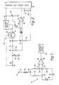
- Figure 2 is a more detailed schematic of a monitoring circuit in accordance with the present invention.
- Referring to Figure 1, the
basic monitoring circuit 10 shown therein comprises a gauge having acoil 12 connected between afirst terminal 14 and afirst junction 16. Asensor 18 having a variable resistance is connected in series with afirst resistor 20 having a fixed resistance between thefirst junction 16 and asecond terminal 22. Asecond junction 24 is defined between thesensor 18 and thefirst resistor 20. Asecond resistor 26 and athird resistor 28, each having a fixed resistance, are connected in series between thefirst junction 16 and thesecond terminal 22. The second andthird resistors third junction 30 therebetween. The second andthird junctions inputs voltage comparator 36. Theoutput 38 of thevoltage comparator 36 is connected to awarning device 40, which may be a warning light and associated driving circuit. Thefirst terminal 14 is connected to a substantially constant supply voltage Vs, and thesecond terminal 22 is connected to electrical ground. - During normal operation of the
monitoring circuit 10, the resistance of thesensor 18 is directly related to the state of the condition it is monitoring. At any moment in time, the current through thecoil 12 of the gauge is dependent on the resistance of thesensor 18, with the gauge providing a visible readout of the actual state of the condition being monitored. Any changes in the monitored condition are reflected by a change in the resistance of thesensor 18, with a consequent change in the current through thecoil 12, and a change in the readout provided by the gauge. Further, thevoltage comparator 36 monitors and compares the voltage difference between the second andthird junctions output 38 of thevoltage comparator 36. - If, however, an abnormal state arises, the voltage difference across the second and
third junctions output 38 of thevoltage comparator 36. This output voltage triggers thewarning device 40 to provide a visible or audible indication of an abnormal state of the condition being monitored. - This arrangement has the advantages over previously known arrangements of providing an accurate warning of an abnormal condition which is not affected by, or dependent on knowing, the resistance of the
coil 12 of the gauge.Sensor 18 and first, second andthird resistors first junction 16, due to resistance changes in thecoil 12, equally affect both sides of the wheatstone bridge, and hence do not affect the predetermined point at which an output voltage is provided at theoutput 38 of thevoltage comparator 36. This arrangement also provides a simple, cheap arrangement for overcoming the problems associated with previously known arrangements. - Knowing the resistive range of the
sensor 18, the values of the first, second andthird resistors third resistors third junction 30 is less than the voltage at thesecond junction 24, and such that during abnormal conditions the voltage at thesecond junction 24 is less than the voltage at thethird junction 30. Thevoltage comparator 36 compares the voltages at the second andthird junctions - Referring now to the more
detailed monitoring circuit 50 shown in Figure 2, this circuit is suitable for monitoring the temperature of the engine coolant of a motor vehicle. Themonitoring circuit 50 comprises atemperature gauge 52, afirst resistor 54, atemperature sensor 56, a second resistor 58, athird resistor 60, avoltage comparator 62, first andsecond terminals third junctions output 74 of thevoltage comparator 62 is connected to a warninglight driver circuit 76 which activates a warning light (not shown) when an output voltage is generated at theoutput 74. - The
temperature gauge 52 is mounted in the instrument cluster (not shown) of the motor vehicle. Thefirst terminal 64 is on thetemperature gauge 52 and is connected with theignition circuit 96 of the motor vehicle. A supply voltage Vs is provided at thefirst terminal 64 when the ignition is switched on. - The
temperature sensor 56 is in the form of a thermistor, and is mounted on the engine block of the motor vehicle to monitor the temperature of the engine coolant. As the temperature of the coolant rises, the resistance of the thermistor falls, and vice versa. The value of thefirst resistor 54 is kept as low as possible so as to maintain an adequate supply voltage across the thermistor, but high enough to provide an adequate signal for thevoltage comparator 62. In a typical example, the thermistor has a resistance of approximately 60 ohms at the temperature at which the warning light is to be activated, and thefirst resistor 54 has a value of 1.6 ohms. The second andthird resistors 58,60 are selected to provide the same ratio at the warning light activation temperature. In a similar manner to the preferred arrangement of thevoltage comparator 36 of Figure 1, thevoltage comparator 62 provides an output voltage at itsoutput 74 when the voltage difference across the second andthird junctions - The
monitoring circuit 50 also includes aresistor 78 which acts to provide hysteresis by feeding back a small voltage when the warning light is activated. This arrangement helps to provide positive activation/deactivation of the warning light, and prevent it flickering. - A
spark gap 80 is connected between thesecond junction 70 and electrical ground. Aresistor 84 is connected between thesecond junction 70 and one of theinputs 86 of thevoltage comparator 62. Adiode 88 connects the other input 90 (which is connected to the third junction 72) of thevoltage comparator 62 to theignition circuit 96 by way of avoltage divider 92. Acapacitor 94 is connected across theinputs voltage comparator 62. These components are optional, but help to make themonitoring circuit 50 more tolerant to the effects of electro-static discharge, radio frequency interference, and abnormal supply voltages. - The
monitoring circuit 50 acts in the same manner as the preferred operation of themonitoring circuit 10 shown in Figure 1 and described above, and has the same advantages. When the engine coolant temperature reaches an abnormally high level, the voltage difference across the second andthird junctions voltage comparator 62, and an output voltage is generated at theoutput 74. The output voltage signal is detected by the warninglight driver circuit 76, and the warning light is lit. - In motor vehicle applications, similar monitoring circuits can be used to activate warning lights when abnormally low fuel level or abnormally low oil pressure in the engine is detected.
Claims (7)
Applications Claiming Priority (2)
| Application Number | Priority Date | Filing Date | Title |
|---|---|---|---|
| GB8911216 | 1989-05-16 | ||
| GB8911216A GB2231963B (en) | 1989-05-16 | 1989-05-16 | Monitoring circuit |
Publications (3)
| Publication Number | Publication Date |
|---|---|
| EP0398509A2 true EP0398509A2 (en) | 1990-11-22 |
| EP0398509A3 EP0398509A3 (en) | 1991-12-11 |
| EP0398509B1 EP0398509B1 (en) | 1994-10-05 |
Family
ID=10656816
Family Applications (1)
| Application Number | Title | Priority Date | Filing Date |
|---|---|---|---|
| EP90304296A Expired - Lifetime EP0398509B1 (en) | 1989-05-16 | 1990-04-20 | Monitoring circuit |
Country Status (6)
| Country | Link |
|---|---|
| EP (1) | EP0398509B1 (en) |
| JP (1) | JPH0812210B2 (en) |
| KR (1) | KR930011101B1 (en) |
| DE (1) | DE69013054T2 (en) |
| ES (1) | ES2060946T3 (en) |
| GB (1) | GB2231963B (en) |
Cited By (2)
| Publication number | Priority date | Publication date | Assignee | Title |
|---|---|---|---|---|
| NL1033451C2 (en) * | 2007-02-26 | 2008-08-27 | Ascom Sweden Ab | Driving circuit for switch state indicator, e.g. LED, comprises Wheatstone bridge and sensor for detecting when this bridge is out of balance |
| US20100109636A1 (en) * | 2008-10-15 | 2010-05-06 | Endress + Hauser Conducta Gesellschaft für Mess- und Regeltechnik mbH + Co. KG | Measuring apparatus and method for detecting moisture at a measurement voltage input of the measuring apparatus |
Families Citing this family (1)
| Publication number | Priority date | Publication date | Assignee | Title |
|---|---|---|---|---|
| JP3851504B2 (en) * | 2000-11-16 | 2006-11-29 | 矢崎総業株式会社 | Automotive sliding door feeder |
Citations (4)
| Publication number | Priority date | Publication date | Assignee | Title |
|---|---|---|---|---|
| US3614731A (en) * | 1970-06-15 | 1971-10-19 | Bourns Inc | Transport vehicle axle bearing alarm |
| US4137770A (en) * | 1977-12-05 | 1979-02-06 | The United States Of America As Represented By The Secretary Of The Navy | Electronic thermostat |
| US4417231A (en) * | 1981-04-10 | 1983-11-22 | Watt Richard E | Engine over-temperature and oil pressure loss audible warning device |
| US4623798A (en) * | 1981-08-17 | 1986-11-18 | Diesel Kiki Co., Ltd. | Thermosensitive switching circuit having comparator with open collector output |
Family Cites Families (4)
| Publication number | Priority date | Publication date | Assignee | Title |
|---|---|---|---|---|
| US3739337A (en) * | 1970-04-14 | 1973-06-12 | Lucas Industries Ltd | Fuel gauge operating circuits for road vehicles |
| US3938117A (en) * | 1974-09-20 | 1976-02-10 | Ford Motor Company | Critical liquid-level warning circuit |
| EP0047599A1 (en) * | 1980-09-06 | 1982-03-17 | Bl Cars Limited | Warning device for vehicle instrument fascia |
| JPS625292A (en) * | 1985-07-01 | 1987-01-12 | 株式会社 写研 | Charactor input unit |
-
1989
- 1989-05-16 GB GB8911216A patent/GB2231963B/en not_active Expired - Fee Related
-
1990
- 1990-04-20 EP EP90304296A patent/EP0398509B1/en not_active Expired - Lifetime
- 1990-04-20 ES ES90304296T patent/ES2060946T3/en not_active Expired - Lifetime
- 1990-04-20 DE DE69013054T patent/DE69013054T2/en not_active Expired - Fee Related
- 1990-05-15 JP JP2125251A patent/JPH0812210B2/en not_active Expired - Lifetime
- 1990-05-16 KR KR1019900007000A patent/KR930011101B1/en not_active IP Right Cessation
Patent Citations (4)
| Publication number | Priority date | Publication date | Assignee | Title |
|---|---|---|---|---|
| US3614731A (en) * | 1970-06-15 | 1971-10-19 | Bourns Inc | Transport vehicle axle bearing alarm |
| US4137770A (en) * | 1977-12-05 | 1979-02-06 | The United States Of America As Represented By The Secretary Of The Navy | Electronic thermostat |
| US4417231A (en) * | 1981-04-10 | 1983-11-22 | Watt Richard E | Engine over-temperature and oil pressure loss audible warning device |
| US4623798A (en) * | 1981-08-17 | 1986-11-18 | Diesel Kiki Co., Ltd. | Thermosensitive switching circuit having comparator with open collector output |
Non-Patent Citations (2)
| Title |
|---|
| ELECTRONIC ENGINEERING, vol. 47, no. 574, December 1975, page 9, Trent Polytechnic, Nottingham, GB; M. PLANT: "Car temperature alarm warns of ice formation" * |
| ELEKTOR, vol. 7, nos. 7/8, July/August 1981, page 58, Canterbury, Kent, GB; "Temperature alarm" * |
Cited By (3)
| Publication number | Priority date | Publication date | Assignee | Title |
|---|---|---|---|---|
| NL1033451C2 (en) * | 2007-02-26 | 2008-08-27 | Ascom Sweden Ab | Driving circuit for switch state indicator, e.g. LED, comprises Wheatstone bridge and sensor for detecting when this bridge is out of balance |
| US20100109636A1 (en) * | 2008-10-15 | 2010-05-06 | Endress + Hauser Conducta Gesellschaft für Mess- und Regeltechnik mbH + Co. KG | Measuring apparatus and method for detecting moisture at a measurement voltage input of the measuring apparatus |
| US8322236B2 (en) * | 2008-10-15 | 2012-12-04 | Endress + Hauser Conducta Gesellschaft für Mess-und Regeltechnik mbH + Co. KG | Measuring apparatus and method for detecting moisture at a measurement voltage input of the measuring apparatus |
Also Published As
| Publication number | Publication date |
|---|---|
| EP0398509A3 (en) | 1991-12-11 |
| ES2060946T3 (en) | 1994-12-01 |
| KR900018891A (en) | 1990-12-22 |
| KR930011101B1 (en) | 1993-11-24 |
| DE69013054T2 (en) | 1995-01-26 |
| GB2231963B (en) | 1993-04-21 |
| DE69013054D1 (en) | 1994-11-10 |
| GB8911216D0 (en) | 1989-07-05 |
| EP0398509B1 (en) | 1994-10-05 |
| JPH0318768A (en) | 1991-01-28 |
| JPH0812210B2 (en) | 1996-02-07 |
| GB2231963A (en) | 1990-11-28 |
Similar Documents
| Publication | Publication Date | Title |
|---|---|---|
| US4513277A (en) | Low fuel indicator system | |
| US3997888A (en) | Charge monitor for electric battery | |
| US5656771A (en) | Motor vehicle cooling system status indicator | |
| EP0080755A1 (en) | Sensor circuit for detecting the water content in fuel and use of such a sensor circuit | |
| US4034336A (en) | Electronic monitor system for automobiles | |
| KR960040771A (en) | Diagnostic Detection Device and Method for Hall Effect Digital Tooth Sensor | |
| CA2003761A1 (en) | Auxiliary battery monitor | |
| US4476530A (en) | Microcomputer electronic control system for automatic transmission of motor vehicle | |
| US4316174A (en) | Threshold detector for a condition indication | |
| US4584554A (en) | Engine oil level detecting device | |
| US4086524A (en) | Charge monitor for electric battery | |
| EP0398509B1 (en) | Monitoring circuit | |
| US4868508A (en) | Trouble detecting circuit for resistive sensor type indicator | |
| US3854281A (en) | Hourmeter for equipment having short operating times | |
| US4656464A (en) | Liquid level detector | |
| US4949069A (en) | Dynamic liquid level indicator | |
| US5233329A (en) | Filter with hysteresis for trip point applications | |
| US5493227A (en) | Misfire-detecting system for internal combustion engines | |
| US6324040B1 (en) | Sensor supply open load detector circuit | |
| US5027656A (en) | Fuel gauge damper circuit with a return to zero gauge circuit | |
| US3335414A (en) | Critical condition warning device | |
| US3334339A (en) | Fuel gas gauge with low-level warning indicator | |
| US3909779A (en) | Vehicle gage alert system using light emitting diodes | |
| US5698974A (en) | Robust gauge driving circuit with pulse modulated input | |
| EP0683383B1 (en) | A damper circuit for a device for indicating the level of a liquid in a tank, particularly for motor vehicles |
Legal Events
| Date | Code | Title | Description |
|---|---|---|---|
| PUAI | Public reference made under article 153(3) epc to a published international application that has entered the european phase |
Free format text: ORIGINAL CODE: 0009012 |
|
| AK | Designated contracting states |
Kind code of ref document: A2 Designated state(s): DE ES FR IT |
|
| PUAL | Search report despatched |
Free format text: ORIGINAL CODE: 0009013 |
|
| AK | Designated contracting states |
Kind code of ref document: A3 Designated state(s): DE ES FR IT |
|
| 17P | Request for examination filed |
Effective date: 19920214 |
|
| 17Q | First examination report despatched |
Effective date: 19930906 |
|
| GRAA | (expected) grant |
Free format text: ORIGINAL CODE: 0009210 |
|
| ITF | It: translation for a ep patent filed |
Owner name: BARZANO' E ZANARDO ROMA S.P.A. |
|
| AK | Designated contracting states |
Kind code of ref document: B1 Designated state(s): DE ES FR IT |
|
| REF | Corresponds to: |
Ref document number: 69013054 Country of ref document: DE Date of ref document: 19941110 |
|
| REG | Reference to a national code |
Ref country code: ES Ref legal event code: FG2A Ref document number: 2060946 Country of ref document: ES Kind code of ref document: T3 |
|
| ET | Fr: translation filed | ||
| PLBE | No opposition filed within time limit |
Free format text: ORIGINAL CODE: 0009261 |
|
| STAA | Information on the status of an ep patent application or granted ep patent |
Free format text: STATUS: NO OPPOSITION FILED WITHIN TIME LIMIT |
|
| 26N | No opposition filed | ||
| PGFP | Annual fee paid to national office [announced via postgrant information from national office to epo] |
Ref country code: FR Payment date: 19970425 Year of fee payment: 8 |
|
| PGFP | Annual fee paid to national office [announced via postgrant information from national office to epo] |
Ref country code: ES Payment date: 19970428 Year of fee payment: 8 |
|
| PGFP | Annual fee paid to national office [announced via postgrant information from national office to epo] |
Ref country code: DE Payment date: 19970612 Year of fee payment: 8 |
|
| PG25 | Lapsed in a contracting state [announced via postgrant information from national office to epo] |
Ref country code: ES Free format text: LAPSE BECAUSE OF EXPIRATION OF PROTECTION Effective date: 19980421 |
|
| PG25 | Lapsed in a contracting state [announced via postgrant information from national office to epo] |
Ref country code: FR Free format text: THE PATENT HAS BEEN ANNULLED BY A DECISION OF A NATIONAL AUTHORITY Effective date: 19980430 |
|
| PG25 | Lapsed in a contracting state [announced via postgrant information from national office to epo] |
Ref country code: DE Free format text: LAPSE BECAUSE OF NON-PAYMENT OF DUE FEES Effective date: 19990202 |
|
| REG | Reference to a national code |
Ref country code: FR Ref legal event code: ST |
|
| REG | Reference to a national code |
Ref country code: ES Ref legal event code: FD2A Effective date: 20000301 |
|
| PG25 | Lapsed in a contracting state [announced via postgrant information from national office to epo] |
Ref country code: IT Free format text: LAPSE BECAUSE OF NON-PAYMENT OF DUE FEES;WARNING: LAPSES OF ITALIAN PATENTS WITH EFFECTIVE DATE BEFORE 2007 MAY HAVE OCCURRED AT ANY TIME BEFORE 2007. THE CORRECT EFFECTIVE DATE MAY BE DIFFERENT FROM THE ONE RECORDED. Effective date: 20050420 |