EP0399059A1 - Implantable medical device with adjustable sensitivity to detect an event relating to a physiological function, and process for using same - Google Patents
Implantable medical device with adjustable sensitivity to detect an event relating to a physiological function, and process for using same Download PDFInfo
- Publication number
- EP0399059A1 EP0399059A1 EP89109157A EP89109157A EP0399059A1 EP 0399059 A1 EP0399059 A1 EP 0399059A1 EP 89109157 A EP89109157 A EP 89109157A EP 89109157 A EP89109157 A EP 89109157A EP 0399059 A1 EP0399059 A1 EP 0399059A1
- Authority
- EP
- European Patent Office
- Prior art keywords
- detector device
- sensitivity
- detected
- minimum value
- detector
- Prior art date
- Legal status (The legal status is an assumption and is not a legal conclusion. Google has not performed a legal analysis and makes no representation as to the accuracy of the status listed.)
- Granted
Links
Images


Classifications
-
- A—HUMAN NECESSITIES
- A61—MEDICAL OR VETERINARY SCIENCE; HYGIENE
- A61N—ELECTROTHERAPY; MAGNETOTHERAPY; RADIATION THERAPY; ULTRASOUND THERAPY
- A61N1/00—Electrotherapy; Circuits therefor
- A61N1/18—Applying electric currents by contact electrodes
- A61N1/32—Applying electric currents by contact electrodes alternating or intermittent currents
- A61N1/36—Applying electric currents by contact electrodes alternating or intermittent currents for stimulation
- A61N1/362—Heart stimulators
- A61N1/37—Monitoring; Protecting
- A61N1/3702—Physiological parameters
- A61N1/3704—Circuits specially adapted therefor, e.g. for sensitivity control
-
- A—HUMAN NECESSITIES
- A61—MEDICAL OR VETERINARY SCIENCE; HYGIENE
- A61N—ELECTROTHERAPY; MAGNETOTHERAPY; RADIATION THERAPY; ULTRASOUND THERAPY
- A61N1/00—Electrotherapy; Circuits therefor
- A61N1/18—Applying electric currents by contact electrodes
- A61N1/32—Applying electric currents by contact electrodes alternating or intermittent currents
- A61N1/36—Applying electric currents by contact electrodes alternating or intermittent currents for stimulation
- A61N1/362—Heart stimulators
- A61N1/365—Heart stimulators controlled by a physiological parameter, e.g. heart potential
Definitions
- the invention relates to a medical device implantable in the body of a living being with a detector device for the detection of events occurring with regard to a physiological function, the sensitivity of the detector device being adjustable.
- the invention also relates to a method for operating such a device.
- the term sensitivity should be understood in such a way that the sensitivity is a threshold value that the signal parameter or parameters taken into account in the detection of a signal corresponding to the physiological function, e.g. have to exceed the amplitude and / or the steepness of an electrical signal in order to lead to a detection.
- a high sensitivity corresponds to a low threshold value, while a low sensitivity corresponds to a high threshold value.
- the sensitivity should be set as high as possible in order to ensure that all occurring events are actually detected and, on the other hand, one cannot exceed a certain sensitivity without the risk of that the detector device incorrectly detects interference superimposed on the signal corresponding to the physiological function as events.
- the sensitivity is therefore usually set to a value that compromises the above criteria.
- a device of the type mentioned is known, which is designed as a pacemaker.
- This pacemaker allows a so-called intracardiac electrocardiogram (IEKG) to be recorded by means of a suitable recording device, in which the signal is shown which is fed to the detector device of the pacemaker.
- IEKG intracardiac electrocardiogram
- recording this signal if a corresponding function of the pacemaker is activated, those events are marked which the detector device of the pacemaker detects as natural heartbeats.
- the attending physician is thus able to initially set the detector device to a sensitivity in which all events in the recorded signal which the physician recognizes as natural heartbeats lead to a detection.
- the attending physician then adjusts the sensitivity of the detector device to a value which is higher by a safety marginal, which he selects depending on the individual circumstances of the respective patient. Since the respective patient only presents himself to the attending doctor at larger intervals after the end of the hospital stay associated with the implantation, there is a risk that, for example as a result of changes in the position of the signals corresponding to the electrical activity of the heart, leading to the detector device leading to the detector device Electrode, conditions result which the setting chosen by the attending doctor no longer corresponds to the sensitivity of the detector device. This can lead to malfunctions, regardless of whether the existing sensitivity setting for the changed conditions is too high or low.
- the invention has for its object to design a device of the type mentioned in such a way that the detector device always works with the required sensitivity without intervention by the attending doctor.
- the invention is also based on the object of specifying a method for operating a device of the type mentioned at the outset which enables the sensitivity of the detector device to be adapted to changing conditions in a safe and energy-saving manner for the patient.
- the sensitivity of the first detector device which represents the actual detector device by means of which the events occurring with regard to the physiological function are detected, is set using a second detector device provided only as a reference.
- the second detector device which preferably has a higher sensitivity than the respectively set sensitivity of the first detector device, operates according to a functional principle that differs from that of the first detector device, that is to say the events relating to the physio logic function is detected on the basis of another signal, or at least the events are detected on the basis of different signal parameters than in the case of the first detector device.
- the same sensitivity is understood here to mean that an event that can just just be detected with the first detector device also detects with the second detector device can be. Greater sensitivity of the second detector device then means that it still detects events which the first detector device is no longer able to detect.
- Claim 2 relates to a preferred embodiment of the invention.
- the sensitivity set is higher by a safety margin, which can be selected depending on the individual circumstances of the respective patient, than the minimum sensitivity value required for the detection of all events detected by the second detector device. Safe operation of the device according to the invention is thus guaranteed under all circumstances.
- a further particularly advantageous embodiment of a device designed as a pacemaker according to the invention is specified in claim 5.
- This embodiment has the advantage that the detection of an event by means of the second detector device takes place a few milliseconds after the detection of the same event by means of the first detector device. Since the detections thus do not occur simultaneously, it is easy to determine whether an event detected by means of the second detector device is also is detected by means of the first detector device, since it only has to be checked in each case whether a detection was also carried out by means of the first detector device shortly before the detection of an event by means of the second detector device.
- the electrode required to establish an electrical connection between the second detector device and the heart of the living being can simultaneously serve to supply the first detector device with the signal corresponding to the electrical activity of the heart.
- the variant of the invention specified in claim 6 offers the advantage that the signal corresponding to the impedance of the heart is obtained by a pure AC measurement. Interfering influences, such as those that result from the fact that the tissue of the heart muscle has a potential deviating from its resting potential shortly after a stimulation pulse, are thereby avoided. In addition, if the measurement is made with an alternating current that has a very high frequency, e.g. several kilohertz, interference of the first detector device is excluded, since it does not respond to such high frequencies.
- the sensitivity is not set continuously, but rather only at successive first times, the time interval between two successive first times having a duration of the order of hours, for example.
- the second detector device therefore only needs to be put into operation at larger time intervals, which has a favorable effect on the energy requirements of the device and thus the service life of one the device feeding battery affects. Since abrupt changes in the sensitivity of the first detector device are generally not necessary, the described intermittent mode of operation means that there are no adverse consequences for the patient.
- the sensitivity of the first detector circuit can be corrected quickly, since according to claim 9, at second times, between which, for example, a time interval with a duration of the order of minutes lies, it is checked whether the set sensitivity of the first detector device is high enough to be able to detect events detected by means of the second detector device.
- the methods according to claims 10 to 13 offer the advantage that a sensitivity of the first detector device is set which is based on the minimum value of the sensitivity of the first detector device, at which the detector detects every event detected by means of the second detector device. This ensures that the sensitivity of the first detector device is not higher than is absolutely necessary, possibly taking safety marginal into account. It is thus ensured that, on the one hand, incorrect detections are avoided and, on the other hand, all events are detected by means of the first detector device.
- the methods according to claims 14 to 17 relate to the determination of the minimum value of the sensitivity of the first detector device.
- the minimum value of the sensitivity of the first detector device In the event of an increase in the minimum value of the sensitivity, it is ensured that the higher minimum value of the sensitivity can be found quickly, so that the number of events that cannot be detected by the first detector device is limited to a minimum.
- the lower minimum value for larger changes is determined step by step at several first times. This offers the advantage that if the minimum value of the sensitivity changes only briefly, the sensitivity of the first detector device is not reduced to such an extent that there is a risk that events cannot be detected.
- the method according to claim 18 has the advantage that at least one of two successive events is detected during the automatic setting of the sensitivity of the first detector device, so that sufficient stimulation of the physiological function is ensured even during the automatic setting of the sensitivity of the first detector device .
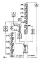
- a cardiac pacemaker designated overall by (1).
- the components of the pacemaker (1) are in a schematically indicated, hermetically sealed housing made of an electrically conductive material, e.g. Titanium.
- a bipolar electrode (3) leads from the pacemaker (1) working in VVI mode to a schematically indicated heart (4) of a living being and is implanted there in a ventricle, preferably the right one.
- the bipolar electrode (3) has two lines (3a, 3b).
- the pacemaker (1) includes, among other things, a microprocessor (5) to which a read-only memory (ROM) (6) and a read-write memory (RAM) (7) are assigned, which are connected via data lines (8, 9) and address lines (10, 11) are connected to the microprocessor (5).
- a line (13) leads from the microprocessor (5) to the RAM (7) and serves to switch the RAM (7) from write to read mode and vice versa.
- a program is stored in the ROM (6), by means of which all functions of the pacemaker are controlled.
- the microprocessor (5) performs a certain function
- the microprocessor (5) sets a certain value for a parameter, this usually means, unless otherwise stated, that data corresponding to the certain value are stored in the RAM (7) to which the microprocessor (5) can access.
- a quartz (14) is connected to the microprocessor (5), which is used to generate the clock signals required for the operation of the microprocessor (5) and also represents the time reference for the operation of the pacemaker (1).
- the microprocessor (5) of the pacemaker (1) has an input / output circuit designated as a whole (15), which has a plurality of channels (16, 17, 18).
- the channel (16) serves to supply the heart (4) with stimulation pulses if necessary.
- the channel (16) therefore has a stimulation pulse generator (20) which has a signal output connected to the line (3a) of the electrode (3) by means of an output line (21) and a connection which carries a reference potential.
- the connection carrying the reference potential is electrically conductively connected to the housing (2). This is illustrated by the fact that both the connection of the stimulation pulse generator (20) carrying the reference potential and the housing (2) are provided with a ground symbol. Although there is a bipolar electrode (3), the stimulation is unipolar.
- the stimulation pulse generator (20) is connected via a line (22) to a corresponding output of the microprocessor (5) can be activated to emit a stimulation pulse.
- Digital data relating to the duration and the amplitude and thus the energy content of the stimulation pulses arrive from the microprocessor (5) via a line (23) to a digital / analog interface (24) which is transmitted to the stimulation pulse generator (20) a control line (25) supplies analog control signals corresponding to the digital data.
- a control line (25) supplies analog control signals corresponding to the digital data.
- the channel (17) has a first detector device (27) which is used exclusively to detect natural heartbeats.
- the first detector device (27) has a signal input connected to the line (3a) of the electrode (3) via an input line (28) and a connection carrying a reference potential.
- the reference potential is the same reference potential that the corresponding connection of the stimulation pulse generator (20) and the housing (2) also carry.
- a bipolar electrode (3) is present, natural heartbeats are also detected using the first detector device (27) in a unipolar manner.
- the second detector device (27) detects a natural heartbeat in the signal corresponding to the electrical activity of the heart (4) which is supplied to it via the line (3a) of the electrode (3), it indicates a signal indicating this via a line (29) a corresponding input of the microprocessor (5).
- the first detector device (27) emits this signal when, in the signal corresponding to the electrical activity of the heart (4), an event with steepness and / or typical for a natural heartbeat Amplitude occurs.
- the microprocessor (5) is connected via a line (30) to a digital / analog interface (31), which sends digital data supplied to it by the microprocessor (5) as corresponding analog signals via a control line (32) to the first detector device ( 27) passes on.
- the digital data or the corresponding analog signals serve to set the sensitivity of the second detector device (27), that is to say the slope and / or amplitude, which an event in the signal corresponding to the electrical activity of the heart (4) must at least have, to be detected as a natural heartbeat.
- the microprocessor Via a control line (33), the microprocessor can also supply the first detector device (27) with a signal that completely blocks it, so that no signals indicating the detection of a natural heartbeat can reach the microprocessor (5).
- the microprocessor (5) receives a signal corresponding to the detection of a natural heartbeat by means of the first detector device (27) via line (29) or if it activates the stimulation pulse generator (20) via line (22) to emit a stimulation pulse, it begins Microprocessor (5) to work as a counter and begins to count a number of clock pulses derived from the oscillation of the quartz (14), which corresponds to a basic time interval. The basic time interval determines the stimulation frequency with which the heart (4) is stimulated in the absence of natural heartbeats. If no signal reaches the microprocessor (5) indicating the detection of a natural heartbeat via the channel (17) during the basic time interval, the microprocessor (5) activates the stimulation pulse when the basic time interval expires via the line (22). Generator (20).
- the microprocessor (5) starts counting a number of clock pulses again, which corresponds to the basic time interval determining the stimulation frequency. If, on the other hand, the microprocessor (5) receives a signal from the first detector device (27) indicating the detection of a natural heartbeat while the base time interval is running, it stops the counting process described, provided that a further time interval, the so-called refractory time, has expired, and starts the counting process described again without the delivery of a stimulation pulse. The detection of the natural heartbeat by means of the first detector device (27) thus inhibits the delivery of a stimulation pulse.
- the refractory period which is generally shorter than the basic time interval that can be programmed, for example, to values between 400 and 2000 milliseconds, lasts approximately between 250 and 450 milliseconds (programmable).
- the refractory period is divided into an absolute refractory period with a duration of usually 125 milliseconds and a relative refractory period, which accounts for the remaining time of the entire set refractory period.
- the refractory period begins at the same time as the base time interval and is determined by the microprocessor (5) in the course of the same counting process that is also used to determine the base time interval.
- the first detector device (27) is blocked in the channel (17), which is achieved by the microprocessor (5) feeding a corresponding signal to the first detector device (27) via the control line (33).
- the microprocessor (5) reactivates the first detector device (27) so that it is able to detect natural heartbeats.
- the microprocessor (5) in contrast to detection after the refractory period has expired, does not abort the counting process for determining the basic time interval, but continues it and closes it with an activation of the stimulation pulse generator (20th ). However, the microprocessor (5) starts the full refractory period again after the detection of a natural heartbeat. It is hereby achieved that in the case of high-frequency disturbances which lead to incorrect detections, irrespective of the occurrence of natural heartbeats, stimulation pulses are generated with the stimulation frequency determined by the respectively programmed basic time interval.
- stimulation pulses are delivered at the stimulation rate determined by the programmed basic time interval, namely until the spontaneous heartbeat rate has dropped below a rate. the period of which corresponds to the refractory period set. This feature allows you to stop certain reentry tachycardias.
- the microprocessor (5) is connected via a line (34) to a telemetry circuit (35) to which a transmit / receive coil (36) is connected.
- the pacemaker (1) is thus able to exchange data with an external programming device (37) with a keyboard (38) and a monitor (39), since the programming device (37) communicates with a user via a line (40) second telemetry circuit (41) is connected, to which a transmit / receive coil (42) is connected again.
- the transmit / receive coil (42) of the telemetry circuit (41) belonging to the programming device (37) is positioned on the body surface of the living being carrying the pacemaker (1), that it is inductively coupled to the transmit / receive coil (36) of the pacemaker (1).
- the channel (18) of the input / output circuitry (15) of the microprocessor (5) is used to provide the microprocessor (5) with data which allow it to do so on the one hand using the program stored in the ROM (6)
- the stimulation intensity that is to say the energy content of the stimulation pulses generated by the stimulation pulse generator (20)
- the channel (18) contains a second detector device (43) which is provided for the detection of both natural and stimulated heartbeats.
- the second detector device (43) has two connections, of which one is connected via line (44) to line (3a) and the other via line (45) to line (3b) of the bipolar electrode (3).
- the second detector device (43) detects not only natural, but, as already mentioned, also stimulated heartbeats, that is to say heartbeats which occur in response to a stimulation pulse emitted by the stimulation pulse generator (20). If the second detector device (43) detects a stimulated or a natural, ie spontaneously occurring, heartbeat, a corresponding signal arrives via a line (46) from the output of the second detector device (43) to a corresponding input of the microprocessor (5).
- the microprocessor (5) is able to block the output of the second detector device (43) via a control line (47) by means of a corresponding signal.
- the sensitivity of the second detector device (43) can be set by means of the microprocessor (5) by feeding digital data via line (48) to a digital / analog interface (49), which the digital / analog interface (49) integrates converts the corresponding analog signal which is fed to the second detector device (43) via a control line (50).
- the analog signal determines the sensitivity of the second detector device, which the microprocessor (5) normally sets higher than the sensitivity of the first detector device (27), but at least the same, in a manner to be explained in more detail.
- the output of which the microprocessor (5) only unlocks after the absolute refractory time has elapsed in the case of the second detector device (43) detections must also be possible during the absolute refractory time in order to Enable detection of stimulated heartbeats.
- the microprocessor (5) thus not only activates the output of the second detector device (43) after the absolute refractory period has elapsed until a natural heartbeat occurs or a stimulation pulse is delivered to detect natural heartbeats, but also a few milliseconds after the delivery of a stimulation pulse short time interval, eg 100 milliseconds, free for the detection of stimulated heartbeats.
- the automatic setting of the energy content of the stimulation pulses generated by the stimulation pulse generator (20) is carried out in such a way that the microprocessor (5) checks, after a stimulation pulse has been given, whether there is an input from the output of the second detector device (43) via line (46) signal indicating the detection of a stimulated heartbeat arrives. If this is not the case, the microprocessor (5) increases the energy content of the next stimulation pulse by supplying digital data to the digital / analog interface (24), which converts it into an analog signal which the stimulation pulse generator (20) thus does sets that this emits a stimulation pulse with an increased energy content compared to the previously existing energy content.
- the microprocessor (5) sets the stimulation pulse generator (20) via the digital / analog interface (24) in such a way that the energy content of the stimulation pulses generated is the sum of a minimum energy content (minimum value of the energy content) at which the second Detector device (43) detects a stimulated heartbeat just after the delivery of a stimulation pulse and corresponds to a safety margin, for example 50% of the minimum energy content.
- the minimum energy content corresponds to the so-called stimulation threshold, which the energy content of a stimulation pulse must at least reach in order to trigger a stimulated heartbeat.
- the microprocessor (5) gradually lowers the energy content of the stimulation pulses from a value at which the second detector device (43) detects a stimulated heartbeat after each stimulation pulse of a sequence of stimulation pulses, at least until individually Stimulation pulses by means of the second detector device (43) can no longer be detected a stimulated heartbeat. Based on the value of the energy content found in this way, the microprocessor (5) gradually increases the energy content of the stimulation pulses again, and precisely until the second detector device (42) detects a stimulated heartbeat again after each stimulation pulse. The value found in this way represents the minimum energy content of the stimulation pulses.
- the described setting of the energy content of the stimulation pulses ensures that, on the one hand, the safety of the patient is guaranteed, since the Stimulation is always carried out with stimulation pulses, the energy content of which is a safety margin above the minimum energy content. On the other hand, it is ensured that the energy requirement of the device due to the delivery of the stimulation pulses is not higher than necessary, since the energy content of the stimulation pulses is always based on the required minimum energy content.
- the sensitivity of the first detector device (27) is automatically set in such a way that the microprocessor (5) checks after the absolute refractory time has elapsed whether a natural heartbeat detected by the second detector device (43) has also been detected by the first detector device (27). This is possible because the microprocessor (5) activates the first and second detector devices (27 and 43) after the expiry of the absolute refractory period. If a natural heartbeat is detected only by means of the second detector device (43), the microprocessor (5) increases the sensitivity of the first detector device (27) by supplying digital data to the digital / analog interface (31) which converts it into an analog signal converts that adjusts the sensitivity of the first detector device (27) in such a way that it is higher than the previously set value.
- the sensitivity of the second detector device (43) must at least correspond to the respectively set sensitivity of the first detector device (27).
- the microprocessor (5) expediently uses the digital / analog Interface (49) the sensitivity of the second detector device (43) significantly higher than the sensitivity of the first detector device (27). It should be noted, however, that the sensitivity of the second detector device (43) must not be increased arbitrarily, since it must be ensured that interference and noise do not lead to incorrect detections.
- the microprocessor (5) uses the digital / analog interface (31) to set the sensitivity of the first detector device (27) in such a way that it is higher than a minimum sensitivity (minimum value of the sensitivity) by a safety margin of sensitivity, in which the first detector device (27) also just detects a natural heartbeat detected by means of the second detector device (43). For example, 50% of the minimum sensitivity can be used as a safety marginal.
- the microprocessor (5) gradually lowers the sensitivity of the first detector device (27) from a value at which the first detector device (27) also detects every natural heartbeat detected by the second detector device (43) until at least individual natural heartbeats detected by means of the second detector device (43) can no longer be detected by means of the first detector device (27).
- the microprocessor (5) gradually increases the sensitivity of the first detector device (27) again, and precisely until the first detector device (27) also each natural heartbeat detected by the second detector device (43) detected.
- the value of the sensitivity of the first detector device (27) found in this way is the minimum sensitivity.
- the described setting of the sensitivity of the first detector device (27) offers the advantage that, on the one hand, in the interest of the patient, the safety marginal of the sensitivity ensures that all natural heartbeats can actually be detected by means of the first detector device (27).
- the sensitivity is set on the basis of the respective minimum sensitivity, it is ensured that the actually existing sensitivity is never higher than is absolutely necessary in the interest of the patient, so that the risk of incorrect detection only is very low.
- FIG. 2 An embodiment of the second detector device (43), which is only schematically indicated in FIG. 1, is shown in FIG. 2.
- This is a detector device that forms a signal that corresponds to the external impedance present between its connections.
- the term external impedance is intended to express that the input impedance of the second detector device (43) is not included in the external impedance. The external impedance is thus, so to speak, the source impedance that the second detector device (43) sees.
- This source impedance results from the impedance of the bipolar electrode (3) schematically indicated in FIG. 2 with its lines (3a and 3b) and the impedance of the contact parts (51a and 51b) which are in electrically conductive connection with the heart when the electrode is implanted. located myocardial tissue.
- the impedance of the heart muscle tissue changes, in accordance with the heart action.
- FIG. 3 in which for a Number of natural heartbeats, the electrical signal corresponding to the electrical activity of the heart, which is denoted by ES, in comparison with a signal which corresponds to the electrical impedance of the heart, which is denoted by IS.
- the electrical signal corresponding to the impedance of the heart and thus the heart action is obtained in the case of the second detector device (43) by having a bipolar modulatable current source (52) which is connected in parallel to the source impedance between the connections of the second detector device (43) is.
- the current source (52) is connected to an oscillator (53), which generates a square-wave signal indicated at P with a constant amplitude and with a constant frequency, which is significantly higher than the expected heartbeat frequency.
- the frequency of the square wave signal comes e.g. 4 kHz in question.
- the oscillator (53) modulates the current source (52) in such a way that it generates an alternating current of constant amplitude which corresponds to the signal of the oscillator (53) with regard to its frequency and curve shape and is symmetrical to the zero line.
- This alternating current which is indicated schematically at Q, flows through the source impedance connected to the second detector device (43).
- the voltage drop resulting from the alternating current over the source impedance is amplified by means of a differential amplifier (54), the inputs of which are connected to the lines (44 and 45) via coupling capacitors (55a and 55b).
- the differential amplifier (54) only amplifies the voltage drop caused by the alternating current, which is a measure of the source impedance present in each case represents. Since the impedance of the electrode (3) does not change, the change in the source impedance takes place exclusively on the basis of the changes in impedance of the heart as a result of the heart action.
- the output signal of the differential amplifier (54) which is indicated at R and also runs symmetrically to the zero line, thus reflects the impedance profile of the heart and thus the heart action.
- the output signal of the differential amplifier (54) is fed to a demodulator (56).
- This signal is fed to a bandpass filter (57), the transfer function of which is selected in such a way that only those signal components which are typical with regard to their frequency or steepness for heartbeats, whether natural or stimulated, can pass the bandpass filter (57).
- the output signal of the bandpass filter (57) reaches the one input of a comparator (58), which compares its amplitude with a threshold value signal, which is fed to its other input via the control line (50).
- the threshold value signal is the output signal of the digital / analog interface (49). If the amplitude of the output signal of the bandpass filter (57) exceeds the level of the threshold signal, the output signal of the comparator (58) jumps off its one extreme value to its other extreme value, with respect to the output signal of the comparator (58) the original state being restored when the amplitude of the output signal of the bandpass filter (57) falls below the threshold value signal.
- the output signal of the comparator (58) has the value logic "0" as long as the amplitude of the output signal of the bandpass filter (57) does not exceed the threshold value signal. If the threshold value signal is exceeded, the output signal of the comparator (58) jumps to logic "1". If the microprocessor (5) sets the threshold value signal via the digital / analog interface (49) in such a way that it corresponds to a level that exceeds the output signal of the bandpass filter (57) occurring with natural as well as stimulated heartbeats, the output of the comparator is at the output (58) a signal is available which has the level logic "1" in the case of the detection of a heartbeat.
- the output signal of the comparator (58) is not fed directly to the microprocessor (5), but reaches the one input of an AND gate (59), the output of which is connected to the line (46) leading to the microprocessor (5).
- the control line (47) is connected to the other input of the AND gate (59).
- the oscillator (53) does not necessarily have to be present as a special circuit.
- the square-wave signal required for modulating the current source (52) and for synchronizing the demodulator (56) can also be derived from the oscillation of the crystal (14) connected to the microprocessor (5).
- the described design of the second detector device (43) offers the advantage in connection with the detection of stimulated heartbeats that the electrical signal corresponding to the impedance of the heart is determined exclusively on the basis of the voltage drop across the source impedance that results from the output from the current source (52) AC occurs. Adverse effects due to the fact that immediately after a stimulation pulse, and at this time the detection of a stimulated heartbeat must take place, the heart muscle tissue in the area of the contact (51a) of the electrode (3) one of the potential of the heart muscle tissue in the area of the contact (51b ) has different potential, so they cannot occur.
- the described embodiment of the second detector device (43) offers the advantage that the detection of one and the same natural heartbeat by means of the first and the second detector device (27 or 43) does not occur simultaneously what happens when processing the corresponding signals using the microprocessor (5) could lead to problems. Rather, the detection by means of the second detector device (43) takes place shortly after the corresponding detection by means of the first detector device (27).
- the microprocessor (5) only has to check whether the detection of a natural heartbeat by means of the second detector device (43) has been preceded by a corresponding detection by means of the first detector device (27). There is no need to fear interference from the first detector device (27) due to the alternating current of the second detector device (43), since the frequency of the alternating current is so high that the first detector device cannot respond to it.
- FIG. 4 illustrates the operating method for the automatic setting of the stimulation intensity, that is to say the energy content of the stimulation pulses. Accordingly, there is no continuous adjustment of the stimulation intensity. Rather, most of the time the pacemaker is in an operating mode designated "NORMAL MODE", in which the second detector device (43) is switched off and the microprocessor (5) does not operate in any way to adjust the energy content of the stimulation pulses. This is done for reasons of energy saving and is possible without disadvantage for the patient, since the As a rule, the stimulus threshold changes only very slowly, so that it is sufficient to make an automatic adjustment of the energy content of the stimulation impulses at longer intervals. In the present case, this takes place at the first points in time, between which there is a time interval in the order of hours.
- the stimulation pulse generator (20) stimulates the heart with stimulation pulses of the energy content A that was set during the last automatic adjustment of the energy content.
- This energy content A is composed of the minimum energy content V, which corresponds to the stimulation threshold, and which is required to trigger a stimulated heartbeat which can be detected by the second detector device (43), and the safety marginal designated by M.
- an additional safety marginal N which can be, for example, 25% of the minimum energy content V, may also be present.
- STIM combined with the statement of a specific energy content A always means that a stimulation pulse of the respective energy content A is emitted.
- the detection of a stimulated heartbeat is illustrated in FIG. 4 by the statement DET, while the absence of detection of a stimulated heartbeat after a stimulation is indicated by the statement NO DET.
- Step I can be, for example, a certain fraction of the maximum possible energy content A max of the stimulation pulses. If this stimulation pulse also leads to the detection of a stimulated heartbeat, this means that the stimulation threshold has dropped. The last available value is therefore set as the new minimum energy content V reduced by step I and the new minimum energy content V increased by the safety marginal M as the new energy content A of the stimulation pulses. This is shown in Fig.
- the stimulus threshold it would be conceivable for the stimulus threshold to drop so far between two successive first times that a lowering of the minimum energy content V by more than one step I would be possible. Nevertheless, in the interest of the patient's safety, only a step I is lowered. Should the stimulus threshold actually stabilize at a level that permits a further reduction in the energy content A, the further reduction takes place early enough in the course of the next automatic setting (s) of the energy content A.
- a stimulation pulse with the maximum possible energy content A max is first emitted to ensure that no more than one stimulation pulse remains unsuccessful.
- the minimum energy content V is increased by a further step I. Before stimulation with the further increased minimum energy content V, however, there is first a stimulation with the maximum energy content A max . Only when a stimulated heartbeat is subsequently detected does the stimulation take place with the increased minimum energy content V. This is repeated until a minimum energy content V is found which leads to the detection of a stimulated heartbeat, whereupon the new energy content A for the "NORMAL MODE" is set as described immediately above, which is corresponding to the number of steps I and the additional safety marginal N higher than the previously available energy content A.
- the maximum energy content A max is set as energy content A for all further stimulations and the second detector device (43) is switched off.
- SIGNAL measures are taken which, when the programmer (37) next communicates with the pacemaker (1), result in a message being output by which the treating physician can recognize that an automatic Setting the energy content A of the stimulation pulses was not possible and therefore the maximum energy content A max was used.
- the next step is a stimulation with the maximum energy content A max .
- a new minimum energy content V and a new energy content A V + M + N of the stimulation pulses are set in the manner already described and this value is returned to "NORMAL MODE".
- the control described at the second points in time is also carried out in the interest of the patient's safety in order to be able to quickly take into account any disturbances or abnormal changes in the stimulus threshold.
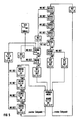
- the operating method shown in FIG. 5 for automatically adjusting the sensitivity of the first detector device (27) is similar to the operating method for automatically adjusting the energy content of the stimulation pulses.
- the pacemaker is in its "NORMAL MODE" mode of operation, in which the second detector device (43) is switched off.
- the adjustment of the sensitivity of the first detector device (27) this is possible without disadvantage for the patient, since the conditions do not generally change so quickly that a continuous adjustment of the sensitivity of the first detector device (27) would be necessary. It is therefore sufficient to set the sensitivity at the first points in time, between which there is a time interval with a duration in the order of hours.
- the first points in time for the automatic setting of the sensitivity of the first detector device (27) are expediently chosen such that they are immediately before or immediately after the first points in time at which the energy content of the stimulation pulses is set automatically.
- the sensitivity of the first detector device (27) corresponds to the sensitivity set in the last automatic setting.
- This sensitivity S is composed of the minimum sensitivity T, which is required in order to be able to also detect a natural heartbeat detected by means of the second detector device (43) with the first detector device (27), and the safety marginal denoted by X. Sensitivity. In special cases, which will be explained later, an additional safety marginal of sensitivity Y, e.g. 25% of the minimum sensitivity T may be present.
- the safety margins X and Y are subtracted from the minimum sensitivity T, since a higher sensitivity S generally corresponds to a smaller numerical value of the sensitivity S. 5, the indication SENSE combined with the indication of a specific sensitivity S always means that the sensitivity S of the first detector device (27) is set to the respective value.
- the detection of a natural heartbeat by means of the first detector device (27) is illustrated in FIG. 5 by the indication DET. If the first detector device (27) fails to detect a heartbeat detected by means of the second detector device (43), this is illustrated by the indication NO DET.
- Step E can be, for example, a certain fraction or a multiple of the maximum possible sensitivity S max of the first detector device (27).
- the sensitivity S is first set to its maximum value S max until the detection of the next natural heartbeat, but this is chosen such that disorders and muscle twitches do not lead to incorrect detection being able to lead. If the next natural heartbeat detected by means of the second detector device (43) is also detected with the first detector device (27) set to maximum sensitivity S max , the first detector device (27) is set to a sensitivity S that corresponds to the last one to the step E corresponds to increased minimum sensitivity T.
- the new minimum sensitivity T is set accordingly.
- S TXY in "NORMAL MODE". This is done so that in the event that a further increase in the minimum sensitivity T should become necessary, appropriate precautions are taken in the interest of the patient's safety.
- the additional safety marginal Y is again eliminated, as is evident from the above explanations.
- the minimum sensitivity T of the first detector device (27) increased by a step E is not sufficient to also detect a natural heartbeat detected by the second detector device (43), the minimum sensitivity T is increased by a further step E.
- the sensitivity of the first detector device (27) is set to its maximum value S max in order to enable the detection of the next natural heartbeat. Only when this detection has been carried out is it checked for the subsequent natural heartbeat detected by means of the second detector device (43) whether detection is also carried out by means of the first detector device (27) with the sensitivity S increased by a further step E. This is repeated until a new minimum sensitivity T is found, with which the first detector device (27) also detects a natural heartbeat detected by means of the second detector device (43). Then the new minimum sensitivity T and the new sensitivity S as described immediately above and set to "NORMAL MODE" with these values, in which case the safety marginal X and the additional safety marginal Y are present.
- the sensitivity S of the first detector device (27 ) set to their maximum value S max .
- measures are taken to ensure that the next time the programmer (37) communicates with the pacemaker (1), the attending physician is informed that the sensitivity of the first detector device (27) has been set to its maximum value S max .
- the first detector device (27) is deactivated and the second detector device (43) takes its place.
- the system returns to "NORMAL MODE". If the detection by means of the first detector device (27) fails to occur for one of the natural heartbeats, the minimum sensitivity T is first newly set, specifically to a value which corresponds to the sensitivity S previously present in "NORMAL MODE". This is followed by the determination of a new minimum sensitivity T in the manner already described above, and after the setting and setting of a new sensitivity S for the first detector device (27) the return to "NORMAL MODE".
- the first and second points in time are expediently determined by the microprocessor (5) counting a corresponding number of clock pulses generated by means of the quartz (14).
- Essential functions of the pacemaker according to the described embodiment are controlled by a suitably programmed microprocessor (5).
- the corresponding functions can also be easily implemented using a conventionally designed control logic.
- the described embodiment of the second detector device (43) is a preferred embodiment of this detector device.
- other suitable detector devices can also be used which likewise detect natural heartbeats in a signal corresponding to the temporal course of the electrical impedance of the heart or also another signal.
Abstract
Description
Die Erfindung betrifft ein in den Körper eines Lebewesens implantierbares medizinisches Gerät mit einer Detektoreinrichtung zur Detektion von bezüglich einer physiologischen Funktion auftretenden Ereignissen, wobei die Empfindlichkeit der Detektoreinrichtung einstellbar ist. Die Erfindung betrifft ausserdem ein Verfahren zum Betrieb eines derartigen Gerätes. Dabei soll der Begriff Empfindlichkeit derart verstanden werden, dass es sich bei der Empfindlichkeit um einen Schwellwert handelt, den der oder die bei der Detektion berücksichtigten Signalparameter eines der physiologischen Funktion entsprechenden Signales, z.B. die Amplitude und/oder die Steilheit eines elektrischen Signals, überschreiten müssen, um zu einer Detektion zu führen. Dabei entspricht einer hohen Empfindlichkeit ein niedriger Schwellwert, während einer niedrigen Empfindlichkeit ein hoher Schwellwert entspricht.The invention relates to a medical device implantable in the body of a living being with a detector device for the detection of events occurring with regard to a physiological function, the sensitivity of the detector device being adjustable. The invention also relates to a method for operating such a device. The term sensitivity should be understood in such a way that the sensitivity is a threshold value that the signal parameter or parameters taken into account in the detection of a signal corresponding to the physiological function, e.g. have to exceed the amplitude and / or the steepness of an electrical signal in order to lead to a detection. A high sensitivity corresponds to a low threshold value, while a low sensitivity corresponds to a high threshold value.
Bei Geräten der eingangs genannten Art tritt das Problem auf, dass man einerseits die Empfindlichkeit möglichst hoch einstellen möchte, um zu gewährleisten, dass tatsächlich auch alle auftretenden Erignisse detektiert werden, und man andererseits eine bestimmte Empfindlichkeit nicht überschreiten kann, ohne dass die Gefahr besteht, dass die Detektoreinrichtung dem der physiologischen Funktion entsprechenden Signal überlagerte Störungen fälschlicherweise als Ereignisse detektiert. In der Praxis wird die Empfindlichkeit daher in der Regel auf einen Wert eingestellt, der einen Kompromiss bezüglich der genannten Kriterien darstellt.The problem with devices of the type mentioned at the outset is that, on the one hand, the sensitivity should be set as high as possible in order to ensure that all occurring events are actually detected and, on the other hand, one cannot exceed a certain sensitivity without the risk of that the detector device incorrectly detects interference superimposed on the signal corresponding to the physiological function as events. In practice, the sensitivity is therefore usually set to a value that compromises the above criteria.
Aus der Druckschrift "Pulse Generator 704 - Physician's Manual", Siemens-Elema AB, Solna, Schweden, März 1985, ist ein Gerät der eingangs genannten Art bekannt, das als Herzschrittmacher ausgebildet ist. Dieser Herzschrittmacher gestattet es, mittels eines geeigneten Aufzeichnungsgerätes ein sogenanntes intrakardielles Elektrokardiogramm (IEKG) aufzuzeichnen, in dem dasjenige Signal dargestellt ist, das der Detektoreinrichtung des Herzschrittmachers zugeführt ist. Bei der Aufzeichnung dieses Signals werden, falls eine entsprechende Funktion des Herzschrittmachers aktiviert ist, diejenigen Ereignisse markiert, die die Detektoreinrichtung des Herzschrittmachers als natürliche Herzschläge detektiert. Der behandelnde Arzt ist somit in der Lage, die Detektoreinrichtung zunächst auf eine Empfindlichkeit einzustellen, in der alle Ereignisse in dem aufgezeichneten Signal, die der Arzt als natürliche Herzschläge erkennt, zu einer Detektion führen. Anschliessend stellt der behandelnde Arzt die Empfindlichkeit der Detektoreinrichtung auf einen um ein Sicherheits-Marginal höheren Wert ein, den er in Abhängigkeit von den individuellen Gegebenheiten des jeweiligen Patienten wählt. Da sich der jeweilige Patient nach Abschluss des mit der Implantation verbundenen Klinikaufenthalts nur in grösseren Abständen bei dem behandelnden Arzt vorstellt, besteht die Gefahr, dass sich, z.B. infolge von Veränderungen der Lage der die der elektrischen Aktivität des Herzens entsprechenden Signale zu der Detektoreinrichtung leitenden endokardiellen Elektrode, Verhältnisse ergeben, denen die vom behandelnden Arzt gewählte Einstellung der Empfindlichkeit der Detektoreinrichtung nicht mehr entspricht. Dies kann zu Fehlfunktionen führen, unabhängig davon, ob die vorhandene Einstellung der Empfindlichkeit für die veränderten Verhältnisse zu hoch oder niedrig ist. Im ersten Falle besteht die Gefahr, dass Störsignale fälschlicherweise als natürliche Herzschläge detektiert werden und demzufolge eine an sich erforderliche Stimulation des Herzens unterbleibt. Im zweiten Falle besteht die Gefahr, dass nicht alle auftretenden natürlichen Herzschläge detektiert werden und demzufolge das Herz des Patienten unnötigerweise stimuliert wird. Beides ist gleichermassen unerwünscht, da zumindest das Wohlbefinden des Patienten beeinträchtigt wird.From the publication "Pulse Generator 704 - Physician's Manual", Siemens-Elema AB, Solna, Sweden, March 1985, a device of the type mentioned is known, which is designed as a pacemaker. This pacemaker allows a so-called intracardiac electrocardiogram (IEKG) to be recorded by means of a suitable recording device, in which the signal is shown which is fed to the detector device of the pacemaker. When recording this signal, if a corresponding function of the pacemaker is activated, those events are marked which the detector device of the pacemaker detects as natural heartbeats. The attending physician is thus able to initially set the detector device to a sensitivity in which all events in the recorded signal which the physician recognizes as natural heartbeats lead to a detection. The attending physician then adjusts the sensitivity of the detector device to a value which is higher by a safety marginal, which he selects depending on the individual circumstances of the respective patient. Since the respective patient only presents himself to the attending doctor at larger intervals after the end of the hospital stay associated with the implantation, there is a risk that, for example as a result of changes in the position of the signals corresponding to the electrical activity of the heart, leading to the detector device leading to the detector device Electrode, conditions result which the setting chosen by the attending doctor no longer corresponds to the sensitivity of the detector device. This can lead to malfunctions, regardless of whether the existing sensitivity setting for the changed conditions is too high or low. In the first case, there is a risk that interference signals are erroneously detected as natural heartbeats and consequently no stimulation of the heart that is required per se is omitted. In the second case there is a risk that not all occurring natural heartbeats will be detected and consequently the patient's heart will be stimulated unnecessarily. Both are equally undesirable, since at least the patient's well-being is impaired.
Der Erfindung liegt die Aufgabe zugrunde, ein Gerät der eingangs genannten Art so auszubilden, dass die Detektoreinrichtung ohne Eingriffe des behandelnden Arztes stets mit der erforderlichen Empfindlichkeit arbeitet. Der Erfindung liegt ausserdem die Aufgabe zugrunde, ein Verfahren zum Betrieb eines Gerätes der eingangs genannten Art anzugeben, das auf für den Patienten sichere und energiesparende Weise eine Anpassung der Empfindlichkeit der Detektoreinrichtung an sich verändernde Verhältnisse ermöglicht.The invention has for its object to design a device of the type mentioned in such a way that the detector device always works with the required sensitivity without intervention by the attending doctor. The invention is also based on the object of specifying a method for operating a device of the type mentioned at the outset which enables the sensitivity of the detector device to be adapted to changing conditions in a safe and energy-saving manner for the patient.
Der das Gerät betreffende Teil der Aufgabe wird durch ein Gerät mit den Merkmalen des Patentanspruches 1 gelöst. Demnach wird also die Empfindlichkeit der ersten Detektoreinrichtung, die die eigentliche Detektoreinrichtung darstellt, mittels derer die bezüglich der physiologischen Funktion auftretenden Ereignisse detektiert werden, anhand einer nur als Referenz vorgesehenen zweiten Detektoreinrichtung eingestellt. Dabei ist es zweckmässig, wenn die zweite Detektoreinrichtung, die vorzugsweise eine höhere Empfindlichkeit als die jeweils eingestellte Empfindlichkeit der ersten Detektoreinrichtung aufweist, nach einem von dem der ersten Detektoreinrichtung abweichenden Funktionsprinzip arbeitet, also die Ereignisse bezüglich der physio logischen Funktion anhand eines anderen Signales detektiert, oder wenigstens die Ereignisse anhand anderer Signalparameter als im Falle der ersten Detektoreinrichtung detektiert. Da unter diesen Voraussetzungen die Empfindlichkeiten der beiden Detektoreinrichtungen unter Umständen nicht mehr direkt ihrem Zahlenwert nach verglichen werden können, soll hier unter gleicher Empfindlichkeit verstanden werden, dass ein Ereignis, das mit der ersten Detektoreinrichtung gerade noch detektiert werden kann, auch mit der zweiten Detektoreinrichtung detektiert werden kann. Eine grössere Empfindlichkeit der zweiten Detektoreinrichtung bedeutet dann, dass diese noch Ereignisse detektiert, die die erste Detektoreinrichtung nicht mehr zu detektieren vermag.The part of the task relating to the device is achieved by a device having the features of patent claim 1. Accordingly, the sensitivity of the first detector device, which represents the actual detector device by means of which the events occurring with regard to the physiological function are detected, is set using a second detector device provided only as a reference. In this case, it is expedient if the second detector device, which preferably has a higher sensitivity than the respectively set sensitivity of the first detector device, operates according to a functional principle that differs from that of the first detector device, that is to say the events relating to the physio logic function is detected on the basis of another signal, or at least the events are detected on the basis of different signal parameters than in the case of the first detector device. Since under these conditions the sensitivities of the two detector devices can no longer be directly compared in terms of their numerical value, the same sensitivity is understood here to mean that an event that can just just be detected with the first detector device also detects with the second detector device can be. Greater sensitivity of the second detector device then means that it still detects events which the first detector device is no longer able to detect.
Der Patentanspruch 2 hat eine bevorzugte Ausführungsform der Erfindung zum Gegenstand. Bei dieser Ausführungsform liegt die eingestellte Empfindlichkeit jeweils um ein in Abhängigkeit von den bei dem jeweiligen Patienten vorliegenden individuellen Gegebenheiten wählbares Sicherheits-Marginal höher, als der zur Detektion aller mittels der zweiten Detektoreinrichtung detektierte Ereignisse erforderliche Mindestwert der Empfindlichkeit. Somit ist unter allem Umständen ein sicherer Betrieb des erfindungsgemässen Gerätes gewährleistet.Claim 2 relates to a preferred embodiment of the invention. In this embodiment, the sensitivity set is higher by a safety margin, which can be selected depending on the individual circumstances of the respective patient, than the minimum sensitivity value required for the detection of all events detected by the second detector device. Safe operation of the device according to the invention is thus guaranteed under all circumstances.
Eine weitere besonders vorteilhafte Ausführungsform eines als Herzschrittmacher ausgebildeten erfindungsgemässen Gerätes ist im Patentanspruch 5 angegeben. Diese Ausführungsform besitzt den Vorteil, dass die Detektion eines Ereignisses mittels der zweiten Detektoreinrichtung einige Millisekunden nach der Detektion des gleichen Ereignisses mittels der ersten Detektoreinrichtung erfolgt. Da somit die Detektionen nicht gleichzeitig auftreten, ist es leicht feststellbar, ob ein mittels der zweiten Detektoreinrichtung detektiertes Ereignis auch mittels der ersten Detektoreinrichtung detektiert wird, da jeweils nur geprüft werden muss, ob kurzzeitig vor der Detektion eines Ereignisses mittels der zweiten Detektoreinrichtung eine Detektion auch mittels der ersten Detektoreinrichtung erfolgt ist. Die zur Herstellung einer elektrischen Verbindung der zweiten Detektoreinrichtung mit dem Herzen des Lebewesens erforderliche Elektrode kann übrigens gleichzeitig dazu dienen, der ersten Detektoreinrichtung dass der elektrischen Aktivität des Herzens entsprechende Signal zuzuführen.A further particularly advantageous embodiment of a device designed as a pacemaker according to the invention is specified in claim 5. This embodiment has the advantage that the detection of an event by means of the second detector device takes place a few milliseconds after the detection of the same event by means of the first detector device. Since the detections thus do not occur simultaneously, it is easy to determine whether an event detected by means of the second detector device is also is detected by means of the first detector device, since it only has to be checked in each case whether a detection was also carried out by means of the first detector device shortly before the detection of an event by means of the second detector device. Incidentally, the electrode required to establish an electrical connection between the second detector device and the heart of the living being can simultaneously serve to supply the first detector device with the signal corresponding to the electrical activity of the heart.
Die im Patentanspruch 6 angegebene Variante der Erfindung bietet den Vorteil, dass das der Impedanz des Herzens entsprechende Signal durch eine reine Wechselstrom-Messung gewonnen wird. Störende Einflüsse, wie sie etwa dadurch auftreten können, dass das Gewebe des Herzmuskels kurz nach einem Stimulationsimpuls ein von seinem Ruhepotential abweichendes Potential führt, sind dadurch vermieden. Ausserdem sind, falls die Messung mit einem Wechselstrom erfolgt, der eine sehr hohe Frequenz, z.B. mehrere Kilohertz, besitzt, Störungen der ersten Detektoreinrichtung ausgeschlossen, da diese auf derart hohe Frequenzen nicht anspricht.The variant of the invention specified in
Der das Verfahren betreffende Teil der Aufgabe ist erfindungsgemäss durch das im Patentanspruch 8 angegebene Verfahren gelöst. Demnach erfolgt also die Einstellung der Empfindlichkeit nicht kontinuierlich, sondern jeweils nur zu aufeinanderfolgenden ersten Zeitpunkten, wobei das Zeitintervall zwischen zwei aufeinanderfolgenden ersten Zeitpunkten beispielsweise eine Dauer in der Grössenordnung von Stunden besitzen kann. Die zweite Detektoreinrichtung braucht also nur in grösseren Zeitabständen in Betrieb genommen zu werden, was sich günstig auf den Energiebedarf des Geräts und damit die Lebensdauer einer das Gerät speisenden Batterie auswirkt. Da sprunghafte Änderungen der Empfindlichkeit der ersten Detektoreinrichtung in der Regel nicht erforderlich sind, sind durch die beschriebene intermittierende Betriebsweise keine nachteiligen Folgen für den Patienten zu befürchten. Dennoch kann im Falle von etwaigen Störungen rasch eine Korrektur der Empfindlichkeit der ersten Detektorschaltung erfolgen, da gemäss Patentanspruch 9 zu zweiten Zeitpunkten, zwischen denen beispielsweise ein Zeitintervall mit einer Dauer in der Grössenordnung von Minuten liegt, überprüft wird, ob die eingestellte Empfindlichkeit der ersten Detektoreinrichtung hoch genug ist, um mittels der zweiten Detektoreinrichtung detektierte Ereignisse detektieren zu können.The part of the task relating to the method is achieved according to the invention by the method specified in claim 8. Accordingly, the sensitivity is not set continuously, but rather only at successive first times, the time interval between two successive first times having a duration of the order of hours, for example. The second detector device therefore only needs to be put into operation at larger time intervals, which has a favorable effect on the energy requirements of the device and thus the service life of one the device feeding battery affects. Since abrupt changes in the sensitivity of the first detector device are generally not necessary, the described intermittent mode of operation means that there are no adverse consequences for the patient. Nevertheless, in the event of any malfunctions, the sensitivity of the first detector circuit can be corrected quickly, since according to
Die Verfahren gemäss den Patentansprüchen 10 bis 13 bieten den Vorteil, dass eine Empfindlichkeit der ersten Detektoreinrichtung eingestellt wird, die sich am Mindestwert der Empfindlichkeit der ersten Detektoreinrichtung orientiert, bei dem diese jedes mittels der zweiten Detektoreinrichtung detektierte Ereignis detektiert. Hierdurch ist gewährleistet, dass die Empfindlichkeit der ersten Detektoreinrichtung nicht höher ist, als dies, gegebenenfalls unter Berücksichtigung von Sicherheits-Marginalen, unbedingt erforderlich ist. Es ist also sichergestellt, dass einerseits Fehldetektionen vermieden sind und andererseits alle Ereignisse mittels der ersten Detektoreinrichtung detektiert werden.The methods according to
Die Verfahren gemäss den Patentansprüchen 14 bis 17 betreffen die Ermittlung des Mindestwertes der Empfindlichkeit der ersten Detektoreinrichtung. Dabei ist für den Fall einer Erhöhung des Mindestwertes der Empfindlichkeit sichergestellt, dass der höhere Mindestwert der Empfindlichkeit rasch gefunden werden kann, so dass die Zahl von Ereignissen, die mittels der ersten Detektoreinrichtung nicht detektiert werden können, auf ein Mindestmass beschränkt ist. Für den Fall einer Verringerung des Mindestwertes der Empfindlichkeit wird der geringere Mindeswert bei grösseren Änderungen schrittweise zu mehreren ersten Zeitpunkten ermittelt. Dies bietet den Vorteil, dass bei nur kurzzeitigen Änderungen des Mindestwertes der Empfindlichkeit die Empfindlichkeit der ersten Detektoreinrichtung nicht so weit gesenkt wird, dass die Gefahr besteht,dass Ereignisse nicht detektiert werden können.The methods according to
Mit dem Verfahren gemäss Patentanspruch 18 wird der Vorteil erziehlt, dass während der selbsttätigen Einstellung der Empfindlichkeit der ersten Detektoreinrichtung von zwei aufeinanderfolgenden Ereignissen wenigstens eines detektiert wird, so dass auch während der selbsttätigen Einstellung der Empfindlichkeit der ersten Detektoreinrichtung eine ausreichende Stimulation der physiologischen Funktion sichergestellt ist.The method according to
Die Erfindung wird nachfolgend anhand der beigefügten Zeichnungen näher erläutert. Es zeigen:
- Fig. 1 ein Blockschaltbild eines als Herzschrittmacher ausgebildeten erfindungsgemässen Gerätes,
- Fig. 2 ein Blockschaltbild der zweiten Detektoreinrichtung des Herzschrittmachers gemäss Fig. 1,
- Fig. 3 für eine Anzahl natürliche Herzschläge das der elektrischen Aktivität des Herzens entsprechende Signal sowie das entsprechende der Impedanz des Herzens entsprechende Signal,
- Fig. 4 ein ein Betriebsverfahren zur selbsttätigen Einstellung des Energiegehaltes der Stimulationsimpulse des Herzschrittmachers gemäss Fig. 1 verdeutlichendes Flussdiagram, und
- Fig. 5 ein ein Betriebsverfahren zur selbsttätigen Einstellung der Empfindlichkeit der ersten Detektoreinrichtung des Herzschrittmachers gemäss Fig. 1 verdeutlichendes Flussdiagramm.
- 1 is a block diagram of an inventive device designed as a pacemaker,
- 2 shows a block diagram of the second detector device of the pacemaker according to FIG. 1,
- 3 shows the signal corresponding to the electrical activity of the heart and the corresponding signal corresponding to the impedance of the heart for a number of natural heartbeats,
- FIG. 4 shows a flow diagram illustrating an operating method for automatically setting the energy content of the stimulation pulses of the pacemaker according to FIG. 1, and
- FIG. 5 is a flow chart illustrating an operating method for automatically adjusting the sensitivity of the first detector device of the pacemaker according to FIG. 1.
In der Fig. 1 ist die Erfindung anhand eines insgesamt mit (1) bezeichneten Herzschrittmachers dargestellt. Die Bauteile des Herzschrittmachers (1) sind in einem schematisch angedeuteten, hermetisch dichten Gehäuse aus einem elektrisch leitenden Werkstoff, z.B. Titan, aufgenommen. Von dem im VVI-Mode arbeitenden Herzschrittmacher (1) führt eine bipolare Elektrode (3) zu einem schematisch angedeuteten Herz (4) eines Lebewesens und ist dort in ein Ventrikel, vorzugsweise das rechte, eingepflanzt. Die bipolare Elektrode (3) besitzt zwei Leitungen (3a, 3b).1, the invention is illustrated with the aid of a cardiac pacemaker designated overall by (1). The components of the pacemaker (1) are in a schematically indicated, hermetically sealed housing made of an electrically conductive material, e.g. Titanium. A bipolar electrode (3) leads from the pacemaker (1) working in VVI mode to a schematically indicated heart (4) of a living being and is implanted there in a ventricle, preferably the right one. The bipolar electrode (3) has two lines (3a, 3b).
Der Herzschrittmacher (1) umfasst u.a. einen Mikroprozessor (5), dem ein Nur-Lese-Speicher (ROM) (6) und ein Schreib-Lese-Speicher (RAM) (7) zugeordnet sind, die über Datenleitungen (8, 9) und Adressleitungen (10, 11) mit dem Mikroprozessor (5) in Verbindung stehen. Zu dem RAM (7) führt von dem Mikroprozessor (5) ausserdem eine Leitung (13), die zum Umschalten des RAM (7) von Schreib- auf Lesebetrieb und umgekehrt dient. In dem ROM (6) ist ein Programm gespeichert, mittels dessen sämtliche Funktionen des Herzschrittmachers gesteuert werden. Wenn also im folgenden die Rede davon ist, dass der Mikroprozessor (5) eine bestimmte Funktion ausführt, so ist darunter zu verstehen, dass der Mikroprozessor (5) durch Ausführung des im ROM (6) gespeicherten Programms unter Heranziehung von in dem RAM (7) befindlichen Daten und ihm anderweitig, z.B. über eine Eingangs-Beschaltung, zugeführten Daten zur Ausführung der jeweiligen Funktion tätig wird. Wenn die Rede davon ist, dass der Mikroprozessor (5) für einen Parameter einen bestimmten Wert einstellt, so bedeutet dies in der Regel, falls nichts anderes angegeben ist, dass dem bestimmten Wert entsprechende Daten in dem RAM (7) gespeichert sind, auf die der Mikroprozessor (5) zugreifen kann.The pacemaker (1) includes, among other things, a microprocessor (5) to which a read-only memory (ROM) (6) and a read-write memory (RAM) (7) are assigned, which are connected via data lines (8, 9) and address lines (10, 11) are connected to the microprocessor (5). A line (13) leads from the microprocessor (5) to the RAM (7) and serves to switch the RAM (7) from write to read mode and vice versa. A program is stored in the ROM (6), by means of which all functions of the pacemaker are controlled. If, therefore, in the following it is mentioned that the microprocessor (5) performs a certain function, this means that the microprocessor (5) executes the program stored in the ROM (6) under Use of data in the RAM (7) and data supplied to it in other ways, for example via an input circuit, to carry out the respective function. When it is said that the microprocessor (5) sets a certain value for a parameter, this usually means, unless otherwise stated, that data corresponding to the certain value are stored in the RAM (7) to which the microprocessor (5) can access.
Mit dem Mikroprozessor (5) ist ein Quarz (14) verbunden, der zur Erzeugung der für den Betrieb des Mikroprozessors (5) erforderlichen Taktsignale dient und ausserdem die Zeitreferenz für den Betrieb des Herzschrittmachers (1) darstellt.A quartz (14) is connected to the microprocessor (5), which is used to generate the clock signals required for the operation of the microprocessor (5) and also represents the time reference for the operation of the pacemaker (1).
Der Mikroprozessor (5) des Herzschrittmachers (1) besitzt eine insgesamt mit (15) bezeichnete Eingangs/Ausgangs- Beschaltung, die mehrere Kanäle (16, 17, 18) aufweist.The microprocessor (5) of the pacemaker (1) has an input / output circuit designated as a whole (15), which has a plurality of channels (16, 17, 18).
Der Kanal (16) dient dazu, das Herz (4) erforderlichenfalls mit Stimulationsimpulsen zu versorgen. Der Kanal (16) besitzt daher einen Stimulationsimpuls-Generator (20), der einen mittels einer Ausgangsleitung (21) mit der Leitung (3a) der Elektrode (3) verbundenen Signalausgang und einen ein Bezugspotential führenden Anschluss aufweist. Der das Bezugspotential führende Anschluss ist mit dem Gehäuse (2) elektrisch leitend verbunden. Dies ist dadurch veranschaulicht, dass sowohl der das Bezugspotential führende Anschluss des Stimulationsimpuls-Generators (20) als auch das Gehäuse (2) mit einem Massesymbol versehen sind. Obwohl eine bipolare Elektrode (3) vorhanden ist, erfolgt also die Stimulation unipolar. Der Stimulationsimpuls-Generator (20) ist über eine Leitung (22), die mit einem entsprechenden Ausgang des Mikroprozessors (5) verbunden ist, zur Abgabe eines Stimulationsimpulses aktivierbar. Digitale Daten, die die Dauer und die Amplitude und damit den Energiegehalt der Stimulationsimpulse betreffen, gelangen von dem Mikroprozessor (5) über eine Leitung (23) zu einer Digital/Analog-Schnittstelle (24), die dem Stimulationsimpuls-Generator (20) über eine Steuerleitung (25) den digitalen Daten entsprechende analoge Steuersignale zuführt. Diese stellen den Stimulationsimpuls-Generator (20) derart ein, dass er bei Bedarf Stimulationsimpulse eines bestimmten Energiegehaltes erzeugt und somit das Herz (4) des Lebewesens mit einer bestimmten Stimulationsintensität stimuliert.The channel (16) serves to supply the heart (4) with stimulation pulses if necessary. The channel (16) therefore has a stimulation pulse generator (20) which has a signal output connected to the line (3a) of the electrode (3) by means of an output line (21) and a connection which carries a reference potential. The connection carrying the reference potential is electrically conductively connected to the housing (2). This is illustrated by the fact that both the connection of the stimulation pulse generator (20) carrying the reference potential and the housing (2) are provided with a ground symbol. Although there is a bipolar electrode (3), the stimulation is unipolar. The stimulation pulse generator (20) is connected via a line (22) to a corresponding output of the microprocessor (5) can be activated to emit a stimulation pulse. Digital data relating to the duration and the amplitude and thus the energy content of the stimulation pulses arrive from the microprocessor (5) via a line (23) to a digital / analog interface (24) which is transmitted to the stimulation pulse generator (20) a control line (25) supplies analog control signals corresponding to the digital data. These set the stimulation pulse generator (20) in such a way that, if necessary, it generates stimulation pulses of a certain energy content and thus stimulates the heart (4) of the living being with a certain stimulation intensity.
Der Kanal (17) besitzt eine erste Detektoreinrichtung (27), die ausschliesslich dazu dient natürliche Herzschläge zu detektieren. Die erste Detektoreinrichtung (27) besitzt einen mit der Leitung (3a) der Elektrode (3) über eine Eingangsleitung (28) verbundenen Signaleingang und einen ein Bezugspotential führenden Anschluss. Dabei handelt sich bei dem Bezugspotential, wie durch das Massesymbol deutlich wird, um das gleiche Bezugspotential, das auch der entsprechende Anschluss des Stimulationsimpuls-Generators (20) und das Gehäuse (2) führen. Obwohl eine bipolare Elektrode (3) vorhanden ist, erfolgt also auch die Detektion natürlicher Herzschläge mittels der ersten Detektoreinrichtung (27) unipolar. Detektiert die zweite Detektoreinrichtung (27) in dem ihr über die Leitung (3a) der Elektrode (3) zugeführten, der elektrischen Aktivität des Herzens (4) entsprechenden Signal einen natürlichen Herzschlag, gibt sie über eine Leitung (29) ein dies anzeigendes Signal an einen entsprechenden Eingang des Mikroprozessors (5). Diese Signal gibt die erste Detektoreinrichtung (27) dann ab, wenn in dem der elektrischen Aktivität des Herzens (4) entsprechenden Signal ein Ereignis mit für einen natürlichen Herzschlag typischer Steilheit und/oder Amplitude auftritt. Der Mikroprozessor (5) ist über eine Leitung (30) mit einer Digital/Analog-Schnittstelle (31) verbunden, die ihr von dem Mikroprozessor (5) zugeführte digitale Daten als entsprechende analoge Signale über eine Steuerleitung (32) an die erste Detektoreinrichtung (27) weitergibt. Die digitalen Daten bzw. die entsprechenden analogen Signale dienen dazu, die Empfindlichkeit der zweiten Detektoreinrichtung (27), also diejenige Steilheit und/oder Amplitude, einzustellen, die ein Ereignis in dem der elektrischen Aktivität des Herzens (4) entsprechenden Signal wenigstens aufweisen muss, um als natürlicher Herzschlag detektiert zu werden. Über eine Steuerleitung (33) kann der Mikroprozessor ausserdem der ersten Detektoreinrichtung (27) ein Signal zuführen, das diese völlig sperrt, so dass keine auf die Detektion eines natürlichen Herzschlages hinweisenden Signale zu dem Mikroprozessor (5) gelangen können.The channel (17) has a first detector device (27) which is used exclusively to detect natural heartbeats. The first detector device (27) has a signal input connected to the line (3a) of the electrode (3) via an input line (28) and a connection carrying a reference potential. As is evident from the ground symbol, the reference potential is the same reference potential that the corresponding connection of the stimulation pulse generator (20) and the housing (2) also carry. Although a bipolar electrode (3) is present, natural heartbeats are also detected using the first detector device (27) in a unipolar manner. If the second detector device (27) detects a natural heartbeat in the signal corresponding to the electrical activity of the heart (4) which is supplied to it via the line (3a) of the electrode (3), it indicates a signal indicating this via a line (29) a corresponding input of the microprocessor (5). The first detector device (27) emits this signal when, in the signal corresponding to the electrical activity of the heart (4), an event with steepness and / or typical for a natural heartbeat Amplitude occurs. The microprocessor (5) is connected via a line (30) to a digital / analog interface (31), which sends digital data supplied to it by the microprocessor (5) as corresponding analog signals via a control line (32) to the first detector device ( 27) passes on. The digital data or the corresponding analog signals serve to set the sensitivity of the second detector device (27), that is to say the slope and / or amplitude, which an event in the signal corresponding to the electrical activity of the heart (4) must at least have, to be detected as a natural heartbeat. Via a control line (33), the microprocessor can also supply the first detector device (27) with a signal that completely blocks it, so that no signals indicating the detection of a natural heartbeat can reach the microprocessor (5).
Erhält der Mikroprozessor (5) über die Leitung (29) ein der Detektion eines natürlichen Herzschlages mittels der ersten Detektoreinrichtung (27) entsprechendes Signal oder aktiviert er über die Leitung (22) den Stimulationsimpuls-Generator (20) zur Abgabe eines Stimulationsimpulses, beginnt der Mikroprozessor (5) als Zähler zu arbeiten und beginnt eine Anzahl von aus der Schwingung des Quarzes (14) abgeleiteten Taktimpulsen abzuzählen, die einem Basis-Zeitintervall entspricht. Das Basis-Zeitintervall bestimmt diejenige Stimulationsfrequenz, mit der das Herz (4) beim Ausbleiben natürlicher Herzschläge stimuliert wird. Gelangt während des Basis-Zeitintervalls über den Kanal (17) kein Signal zu dem Mikroprozessor (5), das die Detektion eines natürlichen Herzschlags anzeigt, aktiviert der Mikroprozessor (5) bei Ablauf des Basis-Zeitintervalls über die Leitung (22) den Stimulationsimpuls-Generator (20). Im Anschluss an die Abgabe eines Stimulationsimpulses beginnt der Mikroprozessor (5) erneut eine Anzahl von Taktimpulsen abzuzählen, die dem die Stimulationsfrequenz bestimmenden Basis-Zeitintervall entspricht. Erhält der Mikroprozessor (5) dagegen während des Laufs des Basis-Zeitintervalls ein die Detektion eines natürlichen Herzschlags anzeigendes Signal von der ersten Detektoreinrichtung (27), bricht er den beschriebenen Zählvorgang ab, sofern ein weiteres Zeitintervall, die sogenannte Refraktärzeit, abgelaufen ist, und beginnt den beschriebenen Zählvorgang von neuem ohne dass die Abgabe eines Stimulationsimpulses erfolgt. Die Detektion des natürlichen Herzschlages mittels der ersten Detektoreinrichtung (27) inhibiert also die Abgabe eines Stimulationsimpulses. Die Refraktärzeit, die grundsätzlich kürzer ist als das beispielsweise auf Werte zwischen 400 und 2000 Millisekunden programmierbare Basis-Zeitintervall, dauert etwa zwischen 250 und 450 Millisekunden (programmierbar). Die Refraktärzeit unterteilt sich in eine absolute Refraktärzeit mit einer Dauer von gewöhnlich 125 Millisekunden und eine relative Refraktärzeit, auf die die restliche Zeit der gesamten eingestellten Refraktärzeit entfällt. Die Refraktärzeit beginnt jeweils gleichzeitig mit dem Basis-Zeitintervall zu laufen und wird von dem Mikroprozessor (5) im Zuge des gleichen Zählvorgangs ermittelt, der auch zur Ermittlung des Basis-Zeitintervalls dient. Während der absoluten Refraktärzeit ist im Kanal (17) die erste Detektoreinrichtung (27) gesperrt, was dadurch erreicht wird, das der Mikroprozessor (5) der ersten Detektoreinrichtung (27) über die Steuerleitung (33) ein entsprechendes Signal zuführt. Infolge der Sperrung der ersten Detektoreinrichtung (27) ist während der Dauer der absoluten Refraktärzeit mittels der ersten Detektoreinrichtung (27) keinerlei Detektion möglich, d.h. entsprechende Signale können nicht zu dem Mikroprozessor (5) gelangen. Nach Ablauf der absoluten Refraktärzeit aktiviert der Mikroprozessor (5) die erste Detektoreinrichtung (27) wieder, so dass diese in der Lage ist, natürliche Herzschläge zu detektieren. Erfolgt eine Detektion während der relativen Refraktärzeit, bricht der Mikroprozessor (5) im Gegensatz zu einer Detektion nach Ablauf der Refraktärzeit den Zählvorgang zur Ermittlung des Basis-Zeitintervalls nicht ab, sondern führt ihn fort und schliesst ihn mit einer Aktivierung des Stimulationsimpuls-Generators (20) ab. Allerdings setzt der Mikroprozessor (5) nach der Detektion eines natürlichen Herzschlages nochmals die volle Refraktärzeit in Gang. Hierdurch wird erreicht, dass im Falle von Hochfrequenzstörungen, die zu Fehldetektionen führen, unabhängig vom Auftreten natürlicher Herzschläge Stimulationsimpulse mit der durch das jeweils programmierte Basis-Zeitintervall bestimmten Stimulationsfrequenz erzeugt werden. Auch wenn die spontane Herzschlagfrequenz so hoch liegt, dass das Auftreten natürlicher Herzschläge jedesmal innerhalb der relativen Refraktärzeit erfolgt, erfolgt eine Abgabe von Stimulationsimpulsen mit der durch das jeweils programmierte Basis-Zeitintervall bestimmten Stimulationsfrequenz, und zwar bis die spontane Herzschlagfrequenz unter eine Frequenz zurückgefallen ist, deren Periodendauer der jeweils eingestellten Refraktärzeit entspricht. Mittels dieser Funktion ist die Beendigung bestimmter Wiedereintrittstachykardien möglich.If the microprocessor (5) receives a signal corresponding to the detection of a natural heartbeat by means of the first detector device (27) via line (29) or if it activates the stimulation pulse generator (20) via line (22) to emit a stimulation pulse, it begins Microprocessor (5) to work as a counter and begins to count a number of clock pulses derived from the oscillation of the quartz (14), which corresponds to a basic time interval. The basic time interval determines the stimulation frequency with which the heart (4) is stimulated in the absence of natural heartbeats. If no signal reaches the microprocessor (5) indicating the detection of a natural heartbeat via the channel (17) during the basic time interval, the microprocessor (5) activates the stimulation pulse when the basic time interval expires via the line (22). Generator (20). Subsequent to When a stimulation pulse is emitted, the microprocessor (5) starts counting a number of clock pulses again, which corresponds to the basic time interval determining the stimulation frequency. If, on the other hand, the microprocessor (5) receives a signal from the first detector device (27) indicating the detection of a natural heartbeat while the base time interval is running, it stops the counting process described, provided that a further time interval, the so-called refractory time, has expired, and starts the counting process described again without the delivery of a stimulation pulse. The detection of the natural heartbeat by means of the first detector device (27) thus inhibits the delivery of a stimulation pulse. The refractory period, which is generally shorter than the basic time interval that can be programmed, for example, to values between 400 and 2000 milliseconds, lasts approximately between 250 and 450 milliseconds (programmable). The refractory period is divided into an absolute refractory period with a duration of usually 125 milliseconds and a relative refractory period, which accounts for the remaining time of the entire set refractory period. The refractory period begins at the same time as the base time interval and is determined by the microprocessor (5) in the course of the same counting process that is also used to determine the base time interval. During the absolute refractory period, the first detector device (27) is blocked in the channel (17), which is achieved by the microprocessor (5) feeding a corresponding signal to the first detector device (27) via the control line (33). As a result of the blocking of the first detector device (27), no detection is possible during the duration of the absolute refractory period by means of the first detector device (27), ie corresponding signals cannot be added to the Microprocessor (5) arrive. After the absolute refractory time has elapsed, the microprocessor (5) reactivates the first detector device (27) so that it is able to detect natural heartbeats. If detection takes place during the relative refractory period, the microprocessor (5), in contrast to detection after the refractory period has expired, does not abort the counting process for determining the basic time interval, but continues it and closes it with an activation of the stimulation pulse generator (20th ). However, the microprocessor (5) starts the full refractory period again after the detection of a natural heartbeat. It is hereby achieved that in the case of high-frequency disturbances which lead to incorrect detections, irrespective of the occurrence of natural heartbeats, stimulation pulses are generated with the stimulation frequency determined by the respectively programmed basic time interval. Even if the spontaneous heartbeat rate is so high that natural heartbeats occur every time within the relative refractory period, stimulation pulses are delivered at the stimulation rate determined by the programmed basic time interval, namely until the spontaneous heartbeat rate has dropped below a rate. the period of which corresponds to the refractory period set. This feature allows you to stop certain reentry tachycardias.
Der Mikroprozessor (5) ist über eine Leitung (34) mit einem Telemetrieschaltkreis (35) verbunden, an den eine Sende/Empfangs-Spule (36) angeschlossen ist. Der Herzschrittmacher (1) ist somit in der Lage, mit einem externen Progammiergerät (37) mit einer Tastatur (38) und einem Monitor (39) Daten auszutauschen, da das Programmiergerät (37) über eine Leitung (40) mit einem zweiten Telemetrieschaltkreis (41) verbunden ist, an den wieder eine Sende/Empfangs-Spule (42) angeschlossen ist. Zum Datenaustausch zwischen dem Herzschrittmacher (1) und dem Programmiergerät (37) wird die Sende/Empfangs-Spule (42) des zu dem Programmiergerät (37) gehörigen Telemetrieschaltkreises (41) so auf der Körperoberfläche des den Herzschrittmacher (1) tragenden Lebewesens positioniert, dass sie mit der Sende/Empfangs-Spule (36) des Herzschrittmachers (1) induktiv gekoppelt ist. Es besteht dann die Möglichkeit, dem Programmiergerät (27) die in dem ROM (6) und dem RAM (7) befindlichen Daten zur Überprüfung zuzuführen. Ausserdem besteht die Möglichkeit, dem RAM (7) des Herzschrittmachers (1) von dem Programmiergerät (37) her veränderte bzw. zusätzliche Daten zuzuführen, die das Betriebsverhalten des Herzschrittmachers (1), also dessen Zussamenspiel mit dem zu stimulierenden Herz (4) beeinflussen und verändern. Dieser Vorgang wird gewöhnlich als Programmierung bezeichnet.The microprocessor (5) is connected via a line (34) to a telemetry circuit (35) to which a transmit / receive coil (36) is connected. The pacemaker (1) is thus able to exchange data with an external programming device (37) with a keyboard (38) and a monitor (39), since the programming device (37) communicates with a user via a line (40) second telemetry circuit (41) is connected, to which a transmit / receive coil (42) is connected again. For data exchange between the pacemaker (1) and the programming device (37), the transmit / receive coil (42) of the telemetry circuit (41) belonging to the programming device (37) is positioned on the body surface of the living being carrying the pacemaker (1), that it is inductively coupled to the transmit / receive coil (36) of the pacemaker (1). It is then possible to supply the programming device (27) with the data in the ROM (6) and the RAM (7) for checking. There is also the possibility of supplying the RAM (7) of the pacemaker (1) with modified or additional data from the programming device (37) which influence the operating behavior of the pacemaker (1), that is to say its interplay with the heart to be stimulated (4) and change. This is commonly referred to as programming.
Der Kanal (18) der Eingangs/Ausgangs-Beschaltung (15) des Mikroprozessors (5) dient dazu, dem Mikroprozessor (5) Daten zur Verfügung zu stellen, die es diesem anhand des in dem ROM (6) gespeicherten Programmes gestatten, einerseits die Stimulationsintensität, also den Energiegehalt der mittels des Stimulationsimpuls-Generator (20) erzeugten Stimulationsimpulse, so einzustellen dass ein Stimulationsimpuls auch tatsächlich einen stimulierten Herzschlag auslöst, und andererseits die Empfindlichkeit der ersten Detektoreinrichtung (27) so einzustellen, dass eine störungsfreie und sichere Detektion aller natürlicher Herzschläge gewährleistet ist. Der Kanal (18) enthält zu diesem Zweck eine zweite Detektoreinrichtung (43), die sowohl zur Detektion natürlicher als auch stimulierter Herzschläge vorgesehen ist. Die zweite Detektoreinrichtung (43) besitzt zwei Anschlüsse, von denen der eine über die Leitung (44) mit der Leitung (3a) und der andere über eine Leitung (45) mit der Leitung (3b) der bipolaren Elektrode (3) verbunden ist. Die zweite Detektoreinrichtung (43) detektiert im Gegensatz zu der bereits beschriebenen ersten Detektoreinrichtung (27) nicht nur natürliche, sondern wie bereits erwähnt auch stimulierte Herzschläge, also Herzschläge, die auf einen durch den Stimulationsimpuls-Generator (20) abgegebenen Stimulationsimpuls hin auftreten. Detektiert die zweite Detektoreinrichtung (43) einen stimulierten oder einen natürlichen, d.h. spontan auftretenden, Herzschlag, gelangt ein entsprechendes Signal über eine Leitung (46) vom Ausgang der zweiten Detektoreinrichtung (43) zu einem entsprechenden Eingang des Mikroprozessors (5). Der Mikroprozessor (5) ist in der Lage, über eine Steuerleitung (47) durch ein entsprechendes Signal den Ausgang der zweiten Detektoreinrichtung (43) zu sperren. Die Empfindlichkeit der zweiten Detektoreinrichtung (43) ist mittels des Mikroprozessors (5) einstellbar, indem dieser über die Leitung (48) einer Digital/Analog-Schnittstelle (49) digitale Daten zuführt, die die Digital/Analog-Schnittstelle (49) in ein entsprechendes analoges Signal umsetzt, das der zweiten Detektoreinrichtung (43) über eine Steuerleitung (50) zugeführt ist. Das analoge Signal bestimmt in noch näher zu erläuternder Weise die Empfindlichkeit der zweiten Detektoreinrichtung, die der Mikroprozessor (5) normalerweise höher als die Empfindlichkeit der ersten Detektoreinrichtung (27), wenigstens jedoch gleich hoch einstellt.The channel (18) of the input / output circuitry (15) of the microprocessor (5) is used to provide the microprocessor (5) with data which allow it to do so on the one hand using the program stored in the ROM (6) To set the stimulation intensity, that is to say the energy content of the stimulation pulses generated by the stimulation pulse generator (20), in such a way that a stimulation pulse actually triggers a stimulated heartbeat, and on the other hand to set the sensitivity of the first detector device (27) in such a way that interference-free and reliable detection of all natural Heartbeat is guaranteed. For this purpose, the channel (18) contains a second detector device (43) which is provided for the detection of both natural and stimulated heartbeats. The second detector device (43) has two connections, of which one is connected via line (44) to line (3a) and the other via line (45) to line (3b) of the bipolar electrode (3). In contrast to the first detector device (27) already described, the second detector device (43) detects not only natural, but, as already mentioned, also stimulated heartbeats, that is to say heartbeats which occur in response to a stimulation pulse emitted by the stimulation pulse generator (20). If the second detector device (43) detects a stimulated or a natural, ie spontaneously occurring, heartbeat, a corresponding signal arrives via a line (46) from the output of the second detector device (43) to a corresponding input of the microprocessor (5). The microprocessor (5) is able to block the output of the second detector device (43) via a control line (47) by means of a corresponding signal. The sensitivity of the second detector device (43) can be set by means of the microprocessor (5) by feeding digital data via line (48) to a digital / analog interface (49), which the digital / analog interface (49) integrates converts the corresponding analog signal which is fed to the second detector device (43) via a control line (50). The analog signal determines the sensitivity of the second detector device, which the microprocessor (5) normally sets higher than the sensitivity of the first detector device (27), but at least the same, in a manner to be explained in more detail.
Anders als im Falle der ersten Detektoreinrichtung (27), deren Ausgang der Mikroprozessor (5) nur nach Ablauf der absoluten Refraktärzeit freischaltet, müssen im Falle der zweiten Detektoreinrichtung (43) Detektionen auch während der absoluten Refraktärzeit erfolgen können, um die Detektion stimulierter Herzschläge zu ermöglichen. Der Mikroprozessor (5) schaltet also den Ausgang der zweiten Detektoreinrichtung (43) nicht nur nach Ablauf der absoluten Refraktärzeit bis zum Auftreten eines natürlichen Herzschlages oder der Abgabe eines Stimulationsimpulses zur Detektion natürlicher Herzschläge frei, sondern ausserdem einige Millisekunden nach der Abgabe eines Stimulationsimpulses für ein kurzes Zeitintervall, z.B. 100 Millisekunden, zur Detektion stimulierter Herzschläge frei. Dabei ist jedoch wesentlich, dass weder die Detektion eines stimulierten Herzschlages noch die Detektion eines natürlichen Herzschlages mittels der zweiten Detektoreinrichtung (43) die Abgabe eines Stimulationsimpulses inhibieren kann. Dies kann nur durch die Detektion eines natürlichen Herzschlages mittels der ersten Detektoreinrichtung (27) unter den zuvor beschriebenen Voraussetzungen erfolgen.Unlike in the case of the first detector device (27), the output of which the microprocessor (5) only unlocks after the absolute refractory time has elapsed, in the case of the second detector device (43) detections must also be possible during the absolute refractory time in order to Enable detection of stimulated heartbeats. The microprocessor (5) thus not only activates the output of the second detector device (43) after the absolute refractory period has elapsed until a natural heartbeat occurs or a stimulation pulse is delivered to detect natural heartbeats, but also a few milliseconds after the delivery of a stimulation pulse short time interval, eg 100 milliseconds, free for the detection of stimulated heartbeats. It is essential, however, that neither the detection of a stimulated heartbeat nor the detection of a natural heartbeat by means of the second detector device (43) can inhibit the delivery of a stimulation pulse. This can only be done by detecting a natural heartbeat using the first detector device (27) under the conditions described above.
Die selbsttätige Einstellung des Energiegehaltes der mittels des Stimulationsimpuls-Generators (20) erzeugten Stimulationsimpulse erfolgt derart, dass der Mikroprozessor (5) nach Abgabe eines Stimulationsimpulses prüft, ob von dem dann freigeschalteten Ausgang der zweiten Detektoreinrichtung (43) über die Leitung (46) ein die Detektion eines stimulierten Herzschlages anzeigendes Signal ankommt. Ist dies nicht der Fall, erhöht der Mikroprozessor (5) den Energiegehalt des nächsten Stimulationsimpulses, indem er der Digital/Analog-Schnittstelle (24) digitale Daten zuführt, die diese in ein analoges Signal umsetzt, das den Stimulationsimpuls-Generator (20) derart einstellt, dass dieser einen Stimulationsimpuls mit einem gegenüber dem zuvor vorhandenen Energiegehalt erhöhten Energiegehalt abgibt. Dies erfolgt solange, bis eine Einstellung für den Energiegehalt der Stimulationsimpulse gefunden ist, bei der die zweite Detektoreinrichtung (43) nach einem Stimulationsimpuls jeweils einen stimulierten Herzschlag detektiert. Dabei stellt der Mikroprozessor (5) über die Digital/Analog-Schnittstelle (24) den Stimulationsimpuls-Generator (20) derart ein, dass der Energiegehalt der erzeugten Stimulationsimpulse der Summe aus einem Mindest-Energiegehalt (Mindestwert des Energiegehaltes), bei dem die zweite Detektoreinrichtung (43) gerade noch nach der Abgabe eines Stimulationsimpulses einen stimulierten Herzschlag detektiert, und einem Sicherheitsmarginal, z.B. 50 % des Mindest-Energiegehaltes, entspricht. Dabei entspricht der Mindest-Energiegehalt der sogenannten Reizschwelle, die der Energiegehalt eines Stimulationsimpulses wenigstens erreichen muss, um einen stimulierten Herzschlag auslösen zu können.The automatic setting of the energy content of the stimulation pulses generated by the stimulation pulse generator (20) is carried out in such a way that the microprocessor (5) checks, after a stimulation pulse has been given, whether there is an input from the output of the second detector device (43) via line (46) signal indicating the detection of a stimulated heartbeat arrives. If this is not the case, the microprocessor (5) increases the energy content of the next stimulation pulse by supplying digital data to the digital / analog interface (24), which converts it into an analog signal which the stimulation pulse generator (20) thus does sets that this emits a stimulation pulse with an increased energy content compared to the previously existing energy content. This continues until a setting for the energy content of the stimulation pulses is found, in which the second detector device (43) after one Stimulation pulse each detected a stimulated heartbeat. The microprocessor (5) sets the stimulation pulse generator (20) via the digital / analog interface (24) in such a way that the energy content of the stimulation pulses generated is the sum of a minimum energy content (minimum value of the energy content) at which the second Detector device (43) detects a stimulated heartbeat just after the delivery of a stimulation pulse and corresponds to a safety margin, for example 50% of the minimum energy content. The minimum energy content corresponds to the so-called stimulation threshold, which the energy content of a stimulation pulse must at least reach in order to trigger a stimulated heartbeat.
Zur Ermittlung des Mindest-Energiegehaltes senkt der Mikroprozessor (5) den Energiegehalt der Stimulationsimpulse ausgehend von einem Wert, bei dem die zweite Detektoreinrichtung (43) nach jedem Stimulationsimpuls einer Folge von Stimulationsimpulsen einen stimulierten Herzschlag detektiert, allmählich so weit ab, bis wenigstens nach einzelnen Stimulationsimpulsen mittels der zweiten Detektoreinrichtung (43) kein stimulierter Herzschlag mehr detektierbar ist. Ausgehend von dem so gefundenen Wert des Energiegehaltes erhöht der Mikroprozessor (5) den Energiegehalt der Stimulationsimpulse allmählich wieder, und zwar gerade so weit, bis die zweite Detektoreinrichtung (42) nach jedem Stimulationsimpuls wieder einen stimulierten Herzschlag detektiert. Der so gefundene Wert stellt den Mindest-Energiegehalt der Stimulationsimpulse dar.To determine the minimum energy content, the microprocessor (5) gradually lowers the energy content of the stimulation pulses from a value at which the second detector device (43) detects a stimulated heartbeat after each stimulation pulse of a sequence of stimulation pulses, at least until individually Stimulation pulses by means of the second detector device (43) can no longer be detected a stimulated heartbeat. Based on the value of the energy content found in this way, the microprocessor (5) gradually increases the energy content of the stimulation pulses again, and precisely until the second detector device (42) detects a stimulated heartbeat again after each stimulation pulse. The value found in this way represents the minimum energy content of the stimulation pulses.
Durch die beschriebene Einstellung des Energiegehaltes der Stimulationsimpulse wird erreicht, dass einerseits die Sicherheit des Patienten gewährleistet ist, da die Stimulation stets mit Stimulationsimpulsen erfolgt, deren Energiegehalt um ein Sicherheitsmarginal oberhalb des Mindest-Energiegehaltes liegt. Andererseit ist sichergestellt, dass der Energiebedarf des Gerätes durch die Abgabe der Stimulationsimpulse nicht höher als nötig ist, da sich der Energiegehalt der Stimulationsimpulse stets an dem erforderlichen Mindest-Energiegehalts orientiert.The described setting of the energy content of the stimulation pulses ensures that, on the one hand, the safety of the patient is guaranteed, since the Stimulation is always carried out with stimulation pulses, the energy content of which is a safety margin above the minimum energy content. On the other hand, it is ensured that the energy requirement of the device due to the delivery of the stimulation pulses is not higher than necessary, since the energy content of the stimulation pulses is always based on the required minimum energy content.
Die selbsttätige Einstellung der Empfindlichkeit der ersten Detektoreinrichtung (27) erfolgt derart, dass der Mikroprozessor (5) nach Ablauf der absoluten Refraktärzeit prüft, ob ein mittels der zweiten Detektoreinrichtung (43) detektierter natürlichen Herzschlag auch mittels der ersten Detektoreinrichtung (27) detektiert wurde. Dies ist möglich, da der Mikroprozessor (5) jeweils nach dem Ablauf der absoluten Refraktärzeit die erste und die zweite Detektoreinrichtung (27 bzw. 43) aktiviert. Erfolgt die Detektion eines natürlichen Herzschlages nur mittels der zweiten Detektoreinrichtung (43) erhöht der Mikroprozessor (5) die Empfindlichkeit der ersten Detektoreinrichtung (27), indem er der Digital/Analog-Schnittstelle (31) digitale Daten zuführt, die diese in ein analoges Signal umwandelt, das die Empfindlichkeit der ersten Detektoreinrichtung (27) derart einstellt, dass diese gegenüber dem zuvor eingestellten Wert erhöht ist. Dies erfolgt solange, bis eine Einstellung für die Empfindlichkeit der ersten Detektoreinrichtung (27) gefunden ist, bei der die erste Detektoreinrichtung (27) mittels der zweiten Detektoreinrichtung (43) detektierte natürliche Herzschläge ebenfalls detektiert. Es versteht sich, dass für diesen Vorgang die Empfindlichkeit der zweiten Detektoreinrichtung (43) wenigstens der jeweils eingestellten Empfindlichkeit der ersten Detektoreinrichtung (27) entsprechen muss. Zweckmässigerweise stellt jedoch der Mikroprozessor (5) mittels der Digital/Analog- Schnittstelle (49) die Empfindlichkeit der zweiten Detektoreinrichtung (43) deutlich höher als die Empfindlichkeit der ersten Detektoreinrichtung (27) ein. Dabei ist jedoch zu beachten, dass die Empfindlichkeit der zweiten Detektoreinrichtung (43) nicht beliebig erhöht werden darf, da sichergestellt sein muss, dass Störungen und Rauschen nicht zu Fehldetektionen führen. Dabei stellt der Mikroprozessor (5) über die Digital/Analog-Schnittstelle (31) die Empfindlichkeit der ersten Detektoreinrichtung (27) derart ein, dass sie um ein Sicherheits-Marginal der Empfindlichkeit höher als eine Mindest-Empfindlichkeit (Mindestwert der Empfindlichkeit) ist, bei der die erste Detektoreinrichtung (27) gerade noch einen mittels der zweiten Detektoreinrichtung (43) detektierten natürlichen Herzschlag ebenfalls detektiert. Als Sicherheits-Marginal kommen z.B. 50 % der Mindest-Empfindlichkeit in Frage.The sensitivity of the first detector device (27) is automatically set in such a way that the microprocessor (5) checks after the absolute refractory time has elapsed whether a natural heartbeat detected by the second detector device (43) has also been detected by the first detector device (27). This is possible because the microprocessor (5) activates the first and second detector devices (27 and 43) after the expiry of the absolute refractory period. If a natural heartbeat is detected only by means of the second detector device (43), the microprocessor (5) increases the sensitivity of the first detector device (27) by supplying digital data to the digital / analog interface (31) which converts it into an analog signal converts that adjusts the sensitivity of the first detector device (27) in such a way that it is higher than the previously set value. This continues until a setting for the sensitivity of the first detector device (27) is found, in which the first detector device (27) also detects natural heartbeats detected by means of the second detector device (43). It goes without saying that for this process the sensitivity of the second detector device (43) must at least correspond to the respectively set sensitivity of the first detector device (27). However, the microprocessor (5) expediently uses the digital / analog Interface (49) the sensitivity of the second detector device (43) significantly higher than the sensitivity of the first detector device (27). It should be noted, however, that the sensitivity of the second detector device (43) must not be increased arbitrarily, since it must be ensured that interference and noise do not lead to incorrect detections. The microprocessor (5) uses the digital / analog interface (31) to set the sensitivity of the first detector device (27) in such a way that it is higher than a minimum sensitivity (minimum value of the sensitivity) by a safety margin of sensitivity, in which the first detector device (27) also just detects a natural heartbeat detected by means of the second detector device (43). For example, 50% of the minimum sensitivity can be used as a safety marginal.
Zur Ermittlung der Mindest-Empfindlichkeit senkt der Mikroprozessor (5) die Empfindlichkeit der ersten Detektoreinrichtung (27) ausgehend von einem Wert, bei dem die erste Detektoreinrichtung (27) jeden mittels der zweiten Detektoreinrichtung (43) detektierten natürlichen Herzschlag ebenfalls detektiert, allmählich so weit ab, bis wenigstens einzelne mittels der zweiten Detektoreinrichtung (43) detektierte natürliche Herzschläge mittels der ersten Detektoreinrichtung (27) nicht mehr detektierbar sind. Ausgehend von dem so gefundenen Wert der Empfindlichkeit erhöht der Mikroprozessor (5) die Empfindlichkeit der ersten Detektoreinrichtung (27) allmählich wieder, und zwar gerade so weit, bis die erste Detektoreinrichtung (27) jeden mittels der zweiten Detektoreinrichtung (43) detektierten natürlichen Herzschlag ebenfalls detektiert. Bei dem so gefundenen Wert der Empfindlichkeit der ersten Detektoreinrichtung (27) handelt es sich um die Mindest-Empfindlichkeit.To determine the minimum sensitivity, the microprocessor (5) gradually lowers the sensitivity of the first detector device (27) from a value at which the first detector device (27) also detects every natural heartbeat detected by the second detector device (43) until at least individual natural heartbeats detected by means of the second detector device (43) can no longer be detected by means of the first detector device (27). On the basis of the sensitivity value found in this way, the microprocessor (5) gradually increases the sensitivity of the first detector device (27) again, and precisely until the first detector device (27) also each natural heartbeat detected by the second detector device (43) detected. The value of the sensitivity of the first detector device (27) found in this way is the minimum sensitivity.
Die beschriebene Einstellung der Empfindlichkeit der ersten Detektoreinrichtung (27) bietet den Vorteil, dass einerseits im Interesse des Patienten durch das Sicherheits-Marginal der Empfindlichkeit gewährleistet ist, dass alle natürlichen Herzschläge mittels der ersten Detektoreinrichtung (27) tatsächlich detektiert werden können. Andererseits ist infolge des Umstandes, dass die Einstellung der Empfindlichkeit auf Grundlage der jeweiligen Mindest-Empfindlichkeit erfolgt, sichergestellt, dass die tatsächlich vorhandene Empfindlichkeit zu keinem Zeitpunkt höher ist, als dies im Interesse des Patienten unbedingt erforderlich ist, so dass die Gefahr von Fehldetektionen nur sehr gering ist.The described setting of the sensitivity of the first detector device (27) offers the advantage that, on the one hand, in the interest of the patient, the safety marginal of the sensitivity ensures that all natural heartbeats can actually be detected by means of the first detector device (27). On the other hand, as a result of the fact that the sensitivity is set on the basis of the respective minimum sensitivity, it is ensured that the actually existing sensitivity is never higher than is absolutely necessary in the interest of the patient, so that the risk of incorrect detection only is very low.
Ein Ausführungsbeispiel für die in Fig. 1 nur schematisch angedeutete zweite Detektoreinrichtung (43) ist in Fig. 2 dargestellt. Es handelt sich hier um eine Detektoreinrichtung, die ein Signal bildet, das der zwischen ihren Anschlüssen vorhandenen äusseren Impedanz entspricht. Dabei soll der Begriff äussere Impedanz zum Ausdruck bringen, dass in der äusseren Impedanz die Eingangsimpedanz der zweiten Detektoreinrichtung (43) nicht enthalten ist. Bei der äusseren Impedanz handelt es sich also sozusagen um die Quellimpedanz, die die zweite Detektoreinrichtung (43) sieht. Diese Quellimpedanz ergibt sich aus der Impedanz der in Fig. 2 schematisch angedeuteten bipolaren Elektrode (3) mit ihren Leitungen (3a und 3b) und der Impedanz des zwischen den bei implantierte Elektrode mit dem Herz in elektrisch leitender Verbindung stehenden Kontaktteilen (51a und 51b) befindlichen Herzmuskelgewebes.An embodiment of the second detector device (43), which is only schematically indicated in FIG. 1, is shown in FIG. 2. This is a detector device that forms a signal that corresponds to the external impedance present between its connections. The term external impedance is intended to express that the input impedance of the second detector device (43) is not included in the external impedance. The external impedance is thus, so to speak, the source impedance that the second detector device (43) sees. This source impedance results from the impedance of the bipolar electrode (3) schematically indicated in FIG. 2 with its lines (3a and 3b) and the impedance of the contact parts (51a and 51b) which are in electrically conductive connection with the heart when the electrode is implanted. located myocardial tissue.
Infolge der Herzaktion ändert sich die Impedanz des Herzmuskelgewebes, und zwar im Einklang mit der Herzaktion. Dies ist aus der Fig. 3 ersichtlich, in der für eine Anzahl natürlicher Herzschläge das der elektrischen Aktivität des Herzens entsprechende elektrische Signal, das mit ES bezeichnet ist, im Vergleich zu einem der elektrischen Impedanz der Herzens entsprechenden Signal, das mit IS bezeichnet ist, dargestellt ist.As a result of the heart action, the impedance of the heart muscle tissue changes, in accordance with the heart action. This can be seen from FIG. 3, in which for a Number of natural heartbeats, the electrical signal corresponding to the electrical activity of the heart, which is denoted by ES, in comparison with a signal which corresponds to the electrical impedance of the heart, which is denoted by IS.
Das der Impedanz des Herzens und damit der Herzaktion entsprechende elektrische Signal wird im Falle der zweiten Detektoreinrichtung (43) dadurch erhalten, dass diese eine bipolare modulierbare Stromquelle (52) aufweist, die parallell zu der Quellimpedanz zwischen die Anschlüsse der zweiten Detektoreinrichtung (43) geschaltet ist. Die Stromquelle (52) ist mit einem Oszillator (53) verbunden, der ein bei P angedeutetes Rechtecksignal mit einer konstanten Amplitude und mit einer konstanten Frequenz erzeugt, die deutlich grösser als die zu erwartender Herzschlagfrequenz ist. Als Frequenz des Rechtecksignals kommen z.B. 4 kHz infrage.The electrical signal corresponding to the impedance of the heart and thus the heart action is obtained in the case of the second detector device (43) by having a bipolar modulatable current source (52) which is connected in parallel to the source impedance between the connections of the second detector device (43) is. The current source (52) is connected to an oscillator (53), which generates a square-wave signal indicated at P with a constant amplitude and with a constant frequency, which is significantly higher than the expected heartbeat frequency. The frequency of the square wave signal comes e.g. 4 kHz in question.
Der Oszillator (53) moduliert die Stromquelle (52) derart, dass diese einen Wechselstrom konstanter Amplitude erzeugt, der hinsichtlich seine Frequenz und Kurvenform dem Signal des Oszillators (53) entspricht und zur Nullinie symmetrisch ist. Dieser Wechselstrom, der bei Q schematisch angedeutet ist, fliesst durch die an die zweite Detektoreinrichtung (43) angeschlossene Quellimpedanz.The oscillator (53) modulates the current source (52) in such a way that it generates an alternating current of constant amplitude which corresponds to the signal of the oscillator (53) with regard to its frequency and curve shape and is symmetrical to the zero line. This alternating current, which is indicated schematically at Q, flows through the source impedance connected to the second detector device (43).
Der über der Quellimpedanz infolge des Wechselstroms entstehende Spannungsabfall wird mittels eines Differenzverstärkers (54) verstärkt, dessen Eingänge über Koppelkondensatoren (55a und 55b) mit den Leitungen (44 und 45) verbunden sind. Infolge der Koppelkondensatoren (55a, 55b) verstärkt der Differenzverstärker (54) nur den durch den Wechselstrom hervorgerufenen Spannungsabfall, der ein Mass für die jeweils vorhandene Quellimpedanz darstellt. Da sich die Impedanz der Elektrode (3) nicht ändert, erfolgt die Änderung der Quellimpedanz ausschliesslich auf Grund der Impedanzänderungen des Herzens infolge der Herzaktion. Das Ausgangssignal des Differenzverstärkers (54), das bei R angedeutet ist und ebenfalls symmetrisch zur Nullinie verläuft, spiegelt also den Impedanzverlauf des Herzens und damit die Herzaktion wieder.The voltage drop resulting from the alternating current over the source impedance is amplified by means of a differential amplifier (54), the inputs of which are connected to the lines (44 and 45) via coupling capacitors (55a and 55b). As a result of the coupling capacitors (55a, 55b), the differential amplifier (54) only amplifies the voltage drop caused by the alternating current, which is a measure of the source impedance present in each case represents. Since the impedance of the electrode (3) does not change, the change in the source impedance takes place exclusively on the basis of the changes in impedance of the heart as a result of the heart action. The output signal of the differential amplifier (54), which is indicated at R and also runs symmetrically to the zero line, thus reflects the impedance profile of the heart and thus the heart action.
Das Ausgangssignal des Differenzverstärkers (54) ist einem Demodulator (56) zugeführt. Dieser demoduliert das Ausgangssignal des Differenzverstärkers (54) infolge des Umstandes, dass ihm das Signal des Oszillators (53) zugeführt ist, in korrekter Phasenbeziehung zu der Modulation der Stromquelle (52), so dass am Ausgang des Demodulators (56) ein bei U angedeutetes, in seinem Verlauf dem Impedanzverlauf des Herzens bzw. der Herzaktion entsprechendes unipolares Signal vorliegt, das im wesentlichen dem Signal IS gemäss FIG 3 entspricht.The output signal of the differential amplifier (54) is fed to a demodulator (56). This demodulates the output signal of the differential amplifier (54) due to the fact that the signal of the oscillator (53) is fed to it, in correct phase relation to the modulation of the current source (52), so that at the output of the demodulator (56) one indicated at U. , in its course there is a unipolar signal corresponding to the impedance course of the heart or the heart action, which essentially corresponds to the signal IS according to FIG. 3.
Dieses Signal ist einem Bandpassfilter (57) zugeführt, dessen Übertragungsfunktion derart gewählt ist, das nur diejenigen Signalanteile, die hinsichtliche ihr Frequenz bzw. Steilheit für Herzschläge, seien es natürliche oder stimulierte, typisch sind, das Bandpassfilter (57) passieren können.This signal is fed to a bandpass filter (57), the transfer function of which is selected in such a way that only those signal components which are typical with regard to their frequency or steepness for heartbeats, whether natural or stimulated, can pass the bandpass filter (57).
Das Ausgangssignal des Bandpassfilters (57) gelangt zu dem einen Eingang eines Komparators (58), der dessen Amplitude mit einem Schwellwertsignals vergleicht, das seinem anderen Eingang über die Steuerleitung (50) zugeführt ist. Bei dem Schwellwertsignal handelt es sich um das Ausgangssignal der Digital/Analog-Schnittstelle (49). Überschreitet die Amplitude des Ausgangssignals des Bandpassfilters (57) den Pegel des Schwellwertsignals, springt das Ausgangssignal des Komparators (58) von seinem einen Extremwert auf seinen anderen Extremwert um, wobei bezüglich des Ausgangssignals des Komparators (58) der Ursprungzustand wieder hergestellt wird, wenn die Amplitude des Ausgangssignals des Bandpassfilters (57) unter das Schwellwertsignal fällt. Das Ausgangssignals des Komparators (58) besitzt den Wert logisch "0", solange die Amplitude des Ausgangssignals des Bandpassfilters (57) das Schwellwertsignal nicht überschreitet. Tritt eine Überschreitung des Schwellwertsignals auf, springt das Ausgangssignal des Komparators (58) auf logisch "1" um. Wenn also der Mikroprozessor (5) über die Digital/Analog-Schnittstelle (49) das Schwellwertsignals derart einstellt, dass es einem Pegel entspricht, die das bei natürlichen wie auch stimulierten Herzschlägen auftretende Ausgangssignal des Bandpassfilter (57) überschreitet, steht am Ausgang des Komparators (58) ein Signal zur Verfügung, das im Falle der Detektion eines Herzschlages den Pegel logisch "1" aufweist.The output signal of the bandpass filter (57) reaches the one input of a comparator (58), which compares its amplitude with a threshold value signal, which is fed to its other input via the control line (50). The threshold value signal is the output signal of the digital / analog interface (49). If the amplitude of the output signal of the bandpass filter (57) exceeds the level of the threshold signal, the output signal of the comparator (58) jumps off its one extreme value to its other extreme value, with respect to the output signal of the comparator (58) the original state being restored when the amplitude of the output signal of the bandpass filter (57) falls below the threshold value signal. The output signal of the comparator (58) has the value logic "0" as long as the amplitude of the output signal of the bandpass filter (57) does not exceed the threshold value signal. If the threshold value signal is exceeded, the output signal of the comparator (58) jumps to logic "1". If the microprocessor (5) sets the threshold value signal via the digital / analog interface (49) in such a way that it corresponds to a level that exceeds the output signal of the bandpass filter (57) occurring with natural as well as stimulated heartbeats, the output of the comparator is at the output (58) a signal is available which has the level logic "1" in the case of the detection of a heartbeat.
Das Ausgangssignal des Komparators (58) wird jedoch dem Mikroprozessor (5) nicht direkt zugeführt, sondern gelangt zu dem einen Eingang eines UND-Gliedes (59), dessen Ausgang mit der zu dem Mikroprozessor (5) führenden Leitung (46) verbunden ist. Mit dem anderen Eingang des UND-Gliedes (59) ist die Steuerleitung (47) verbunden. Es wird somit deutlich, dass nur dann die Detektion eines natürlichen oder stimulierten Herzschlages anzeigende Signale von dem Komparator (58) über die Leitung (46) zu dem Mikroprozessor (5) gelangen können, wenn dieser den Ausgang der zweiten Detektoreinrichtung (43) freischaltet, indem er dem UND-Glied (59) über die Steuerleitung (47) ein Signal mit dem Pegel logisch "1" zuführt, was nur während der im Zusammenhang mit der Fig. 1 erläuterten Zeitintervalle der Fall ist.However, the output signal of the comparator (58) is not fed directly to the microprocessor (5), but reaches the one input of an AND gate (59), the output of which is connected to the line (46) leading to the microprocessor (5). The control line (47) is connected to the other input of the AND gate (59). It is thus clear that signals indicating the detection of a natural or stimulated heartbeat can only reach the microprocessor (5) via the line (46) from the comparator (58) if the latter unlocks the output of the second detector device (43), by supplying the AND gate (59) via the control line (47) with a signal having the logic "1" level, which is only the case during the time intervals explained in connection with FIG. 1.
Es besteht ausserdem in in Fig. 2 nicht dargestellter Weise die Möglichkeit, die gesamte Detektoreinrichtung (43) während solcher Zeiträume, in denen sie nicht benötigt wird, stromlos zu schalten, um den Strombedarf des Herzschrittmachers zu senken.It is also possible, in a manner not shown in FIG. 2, to switch off the entire detector device (43) during periods in which it is not required in order to reduce the current requirement of the pacemaker.
Der Oszillator (53) muss nicht unbedingt als besondere Schaltung vorhanden sein. Das zur Modulation der Stromquelle (52) und zur Synchronisation des Demodulators (56) benötigte Rechtecksignal kann auch aus der Schwingung des mit dem Mirkoprozessor (5) verbundenen Quarzes (14) abgeleitet werden.The oscillator (53) does not necessarily have to be present as a special circuit. The square-wave signal required for modulating the current source (52) and for synchronizing the demodulator (56) can also be derived from the oscillation of the crystal (14) connected to the microprocessor (5).
Die beschriebene Ausbildung der zweiten Detektoreinrichtung (43) bietet im Zusammenhang mit der Detektion stimulierter Herzschläge den Vorteil, dass das der Impedanz des Herzens entsprechende elektrische Signal ausschliesslich auf Grundlage desjenigen Spannungsabfalls über der Quellimpedanz ermittelt wird, der infolge des von der Stromquelle (52) abgegebenen Wechselstromes auftritt. Nachteilige Auswirkungen infolge des Umstandes, das unmittelbar nach einem Stimulationsimpuls, und zu dieser Zeit muss die Detektion eines stimulierten Herzschlages erfolgen, das Herzmuskelgewebe im Bereich des Kontaktes (51a) der Elektrode (3) ein von dem Potential des Herzmuskelgewebes im Bereich des Kontaktes (51b) abweichendes Potential aufweist, können also nicht auftreten.The described design of the second detector device (43) offers the advantage in connection with the detection of stimulated heartbeats that the electrical signal corresponding to the impedance of the heart is determined exclusively on the basis of the voltage drop across the source impedance that results from the output from the current source (52) AC occurs. Adverse effects due to the fact that immediately after a stimulation pulse, and at this time the detection of a stimulated heartbeat must take place, the heart muscle tissue in the area of the contact (51a) of the electrode (3) one of the potential of the heart muscle tissue in the area of the contact (51b ) has different potential, so they cannot occur.
Im Zusammenhang mit der selbsttätigen Einstellung der Empfindlichkeit der ersten Detektoreinrichtung (27) bietet die beschriebene Ausführung der zweiten Detektoreinrichtung (43) den Vorteil, dass die Detektion ein und desselben natürlichen Herzschlages mittels der ersten und der zweiten Detektoreinrichtung (27 bzw. 43) nicht gleichzeitig erfolgt, was bei der Verarbeitung der entsprechenden Signale mittels des Mikroprozessors (5) zu Problemen führen könnte. Vielmehr erfolgt die Detektion mittels der zweiten Detektoreinrichtung (43) kurze Zeit nach der entsprechenden Detektion mittels der ersten Detektoreinrichtung (27). Im Zusammenhang mit der selbsttätigen Einstellung der Empfindlichkeit der ersten Detektoreinrichtung (27) muss der Mikroprozessor (5) also nur überprüfen, ob der Detektion eines natürlichen Herzschlages mittels der zweiten Detektoreinrichtung (43) eine entsprechende Detektion mittels der ersten Detektoreinrichtung (27) vorangegangen ist. Störungen der ersten Detektoreinrichtung (27) durch den Wechselstrom der zweiten Detektoreinrichtung (43) sind nicht zu befürchten, da die Frequenz des Wechselstromes so hoch liegt, dass die erste Detektoreinrichtung darauf nicht ansprechen kann.In connection with the automatic setting of the sensitivity of the first detector device (27), the described embodiment of the second detector device (43) offers the advantage that the detection of one and the same natural heartbeat by means of the first and the second detector device (27 or 43) does not occur simultaneously what happens when processing the corresponding signals using the microprocessor (5) could lead to problems. Rather, the detection by means of the second detector device (43) takes place shortly after the corresponding detection by means of the first detector device (27). In connection with the automatic setting of the sensitivity of the first detector device (27), the microprocessor (5) only has to check whether the detection of a natural heartbeat by means of the second detector device (43) has been preceded by a corresponding detection by means of the first detector device (27). There is no need to fear interference from the first detector device (27) due to the alternating current of the second detector device (43), since the frequency of the alternating current is so high that the first detector device cannot respond to it.
Nachdem im Zusammenhang mit der Fig. 1 bereits beschrieben wurde, wie die selbsttätige Einstellung der Stimulationsintensität und die Einstellung der Empfindlichkeit erfolgen können, werden diesbezügliche Betriebsverfahren im Zusammenhang mit den Figuren 4 und 5 näher erläutert.After it has already been described in connection with FIG. 1 how the automatic setting of the stimulation intensity and the setting of the sensitivity can take place, the relevant operating methods are explained in connection with FIGS. 4 and 5.
Die Fig. 4 verdeutlicht das Betriebsverfahren zur selbsttätigen Einstellung der Stimulationsintensität, also des Energiegehaltes der Stimulationsimpulse. Demnach findet keine kontinuierliche Einstellung der Stimulationsintensität statt. Vielmehr befindet sich der Herzschrittmacher die meiste Zeit in einer mit "NORMAL MODE" bezeichneten Betriebsweise, in der die zweite Detektoreinrichtung (43) stromlos geschaltet ist und der Mikroprozessor (5) in keiner Weise zur Einstellung des Energiegehalts der Stimulationsimpulse tätig wird. Dies geschieht aus Gründen der Energieersparnis und ist ohne Nachteil für den Patienten möglich, da sich die Reizschwelle in der Regel nur sehr langsam ändert, so dass es genügt, eine selbsttätige Einstellung des Energiegehaltes der Stimulationsimpulse in grösseren Zeitabständen vorzunehmen. Im vorliegenden Falle erfolgt dies zu ersten Zeitpunkten, zwischen denen jeweils ein Zeitintervall in der Grössenordnung von Stunden liegt. Während dieser Zeitintervalle stimuliert der Stimulationsimpuls-Generator (20) das Herz mit Stimulationsimpulsen desjenigen Energiegehaltes A, der bei der zuletzt vorgenommenen selbsttätigen Einstellung des Energiegehaltes eingestellt wurde. Dieser Energiegehalt A setzt sich zusammen aus dem der Reizschwelle entsprechenden Mindest- Energiegehalt V, der erforderlich ist, um einen mittels der zweiten Detektoreinrichtung (43) detektierbaren stimulierten Herzschlag auszulösen, und dem mit M bezeichneten Sicherheits-Marginal. In besonderen Fällen, die noch erläutert werden, kann noch ein zusätzliches Sicherheits-Marginal N, das z.B. 25 % des Mindest-Energiegehalts V betragen kann, vorhanden sein.FIG. 4 illustrates the operating method for the automatic setting of the stimulation intensity, that is to say the energy content of the stimulation pulses. Accordingly, there is no continuous adjustment of the stimulation intensity. Rather, most of the time the pacemaker is in an operating mode designated "NORMAL MODE", in which the second detector device (43) is switched off and the microprocessor (5) does not operate in any way to adjust the energy content of the stimulation pulses. This is done for reasons of energy saving and is possible without disadvantage for the patient, since the As a rule, the stimulus threshold changes only very slowly, so that it is sufficient to make an automatic adjustment of the energy content of the stimulation impulses at longer intervals. In the present case, this takes place at the first points in time, between which there is a time interval in the order of hours. During these time intervals, the stimulation pulse generator (20) stimulates the heart with stimulation pulses of the energy content A that was set during the last automatic adjustment of the energy content. This energy content A is composed of the minimum energy content V, which corresponds to the stimulation threshold, and which is required to trigger a stimulated heartbeat which can be detected by the second detector device (43), and the safety marginal designated by M. In special cases, which will be explained later, an additional safety marginal N, which can be, for example, 25% of the minimum energy content V, may also be present.
Dass der Stimulationsimpuls-Generator (20) im "NORMAL MODE" mit dem erwähnten Energiegehalt (A) stimuliert, ist durch die Angabe STIM A = V+M bzw. STIM A = V+M+N verdeutlicht. In der Fig. 4 bedeutet die Angabe STIM verbunden mit der Angabe eines bestimmten Energiegehaltes A übrigens immer, dass ein Stimulationsimpuls des jeweiligen Energiegehaltes A abgegeben wird.That STIM A = V + M or STIM A = V + M + N shows that the stimulation pulse generator (20) stimulates with the aforementioned energy content (A) in "NORMAL MODE". In FIG. 4, the statement STIM combined with the statement of a specific energy content A always means that a stimulation pulse of the respective energy content A is emitted.
Im Zuge der selbsttätigen Einstellung der Stimulationsintensität, die zu jedem ersten Zeitpunkt erfolgt, wird die zweite Detektoreinrichtung aktiviert und zunächst für eine definierte Anzahl von Stimulationsimpulsen, in Fig. 4 sind es beispielhaft vier Stimulationsimpulse mit dem Energiegehalt A = V+M, überprüft, ob die zweite Detektoreinrichtung (43) jeweils einen stimulierten Herzschlag detektiert. Die Detektion eines stimulierten Herzschlages ist in Fig. 4 durch die Angabe DET veranschaulicht während das Ausbleiben der Detektion eines stimulierten Herzschlages nach einer Stimulation mit der Angabe NO DET verdeutlicht ist. Der Energiegehalt A der Stimulationsimpulse beträgt dabei übrigens unabhängig davon, ob zuvor das zusätzliches Sicherheits-Marginal N vorhanden war, A = V+M.In the course of the automatic setting of the stimulation intensity, which takes place at every first point in time, the second detector device is activated and first of all for a defined number of stimulation pulses, in FIG. 4 there are four stimulation pulses with the energy content A = V + M, checked whether the second detector device (43) each has a stimulated heartbeat detected. The detection of a stimulated heartbeat is illustrated in FIG. 4 by the statement DET, while the absence of detection of a stimulated heartbeat after a stimulation is indicated by the statement NO DET. Incidentally, the energy content A of the stimulation pulses is A = V + M, regardless of whether the additional safety marginal N was previously present.
Wird für jeden der definierten Anzahl von Stimulationsimpulsen ein nachfolgender stimulierter Herzschlag detektiert, besitzt der nächste Stimulationsimpuls den zuletzt gefundenen Mindest-Energiegehalt V. Führt auch dieser Stimulationsimpuls zur Detektion eines stimulierten Herzschlages, wird bei der nachfolgenden Stimulation ein Stimulationsimpuls mit einem nochmals um einen definierten Schritt I verringerten Energiegehalt A = V-I abgegeben. Der Schritt I kann z.B. ein bestimmter Bruchteil des maximal möglichen Energiegehaltes Amax der Stimulationsimpulse sein. Führt auch dieser Stimulationsimpuls zur Detektion eines stimulierten Herzschlages, bedeutet dies, dass die Reizschwelle abgesunken ist. Als neuer Mindest-Energiegehalt V wird daher der zuletzt vorhandene Wert vermindert um den Schritt I gesetzt und als neuer Energiegehalt A der Stimulationsimpulse der neue Mindest-Energiegehalt V erhöht um das Sicherheits-Marginal M gesetzt. Dies wird in Fig. 4 durch die Angaben SET V = V-I und SET A = V+M. Im übrigen bedeutet in Fig. 4 die Angabe SET in Verbindung mit der Angabe eines Parameters immer, dass diesem Parameter ein neuer Wert zugeordnet wird. Mit dem neu gesetzten Energiegehalt A, der wohlgemerkt um den Schritt I geringer ist, als der zuvor vorhandene, stimuliert der Herzschrittmacher dann im "NORMAL MODE".If a subsequent stimulated heartbeat is detected for each of the defined number of stimulation pulses, the next stimulation pulse has the last-found minimum energy content V. If this stimulation pulse also leads to the detection of a stimulated heartbeat, a stimulation pulse with a further defined step is triggered during the subsequent stimulation I reduced energy content A = VI delivered. Step I can be, for example, a certain fraction of the maximum possible energy content A max of the stimulation pulses. If this stimulation pulse also leads to the detection of a stimulated heartbeat, this means that the stimulation threshold has dropped. The last available value is therefore set as the new minimum energy content V reduced by step I and the new minimum energy content V increased by the safety marginal M as the new energy content A of the stimulation pulses. This is shown in Fig. 4 by the information SET V = VI and SET A = V + M. Otherwise, in FIG. 4, the specification SET in connection with the specification of a parameter always means that a new value is assigned to this parameter. The pacemaker then stimulates in "NORMAL MODE" with the newly set energy content A, which, mind you, is lower by step I than the previously available one.
Es wäre zwar grundsätzlich denkbar, dass die Reizschwelle zwischen zwei aufeinanderfolgenden ersten Zeitpunkten so weit absinkt, dass eine Absenkung des Mindest-Energiegehaltes V um mehr als einen Schritt I möglich wäre. Dennoch wird im Interesse der Sicherheit des Patienten nur um einen Schritt I abgesenkt. Sollte sich die Reizschwelle tatsächlich auf einem Niveau stabilisieren, das eine weitere Absenkung des Energiegehaltes A gestattet, so erfolgt die weitere Absenkung im Zuge der nächsten selbsttätigen Einstellung(en) des Energiegehaltes A noch frühzeitig genug.In principle, it would be conceivable for the stimulus threshold to drop so far between two successive first times that a lowering of the minimum energy content V by more than one step I would be possible. Nevertheless, in the interest of the patient's safety, only a step I is lowered. Should the stimulus threshold actually stabilize at a level that permits a further reduction in the energy content A, the further reduction takes place early enough in the course of the next automatic setting (s) of the energy content A.
Führt der Stimulationsimpuls mit dem Energiegehalt A = V-I nicht zur Detektion eines stimulierten Herzschlages, bedeutet dies, dass sich die Reizschwelle seit dem letzten ersten Zeitpunkt nicht verändert hat. Daher werden wieder der alte Mindest-Energiegehalt V und der alte Energiegehalt A gesetzt, bevor die Rückkehr in den "NORMAL MODE" erfolgt.If the stimulation pulse with the energy content A = V-I does not lead to the detection of a stimulated heartbeat, this means that the stimulation threshold has not changed since the last first point in time. Therefore, the old minimum energy content V and the old energy content A are set again before returning to the "NORMAL MODE".
Führt bereits die Stimulation mit dem zuletzt gefundenen Mindest-Energiegehalt V nicht zur Detektion eines stimulierten Herzschlages, ist also die Reizschwelle angestiegen, wird zunächst ein Stimulationsimpuls mit dem maximal möglichen Energiegehalt Amax abgegeben, um sicherzustellen, dass nicht mehr als ein Stimulationsimpuls erfolglos bleibt.If the stimulation with the last found minimum energy content V does not lead to the detection of a stimulated heartbeat, i.e. if the stimulation threshold has risen, a stimulation pulse with the maximum possible energy content A max is first emitted to ensure that no more than one stimulation pulse remains unsuccessful.
Wird nach diesem Stimulationsimpuls mit dem maximalen Energiegehalt Amax ein stimulierter Herzschlag detektiert, erfolgt als nächstes eine Stimulation mit einem Energiegehalt A = V+I, der dem letzten Mindest-Energiegehalt V erhöht um einen Schritt I entspricht. Führt dies zur Detektion eines stimulierten Herzschlages, wird der neue Mindest-Energiegehalt V entsprechend festgesetzt. Als neuer Energiegehalt A wird jedoch anders als zuvor nicht nur die Summe aus dem neuen Mindest-Energiegehalt V und dem Sicherheits-Marginal M eingestellt. Vielmehr erfolgt noch eine Erhöhung des Energiegehaltes A um das bereits erwähnte zusätzliche Sicherheits-Marginal N. Dadurch wird bis zum nächsten ersten Zeitpunkt, d.h. bis zur nächsten selbsttätigen Einstellung des Energiegehaltes A, im "NORMAL MODE" mit einem Energiegehalt A = V+M+N stimuliert. Dies geschieht, um für den Fall eines weiteren Ansteigens der Reizschwelle im Interesse der Sicherheit des Patienten bereits entsprechende Vorkehrungen zu treffen. Für den Fall, dass bis zum nächsten ersten Zeitpunkt kein weiterer Anstieg der Reizschwelle auftritt, entfällt, wie sich aus den vorstehenden Ausführungen ergibt, dass zusätzliche Sicherheits-Marginal N wieder.If a stimulated heartbeat is detected after this stimulation pulse with the maximum energy content A max , the next step is a stimulation with an energy content A = V + I, which corresponds to the last minimum energy content V increased by a step I. If this leads to the detection of a stimulated heartbeat, the new minimum energy content V is set accordingly. However, as the new energy content A becomes different than previously set not only the sum of the new minimum energy content V and the safety marginal M. Rather, there is an increase in the energy content A by the additional safety marginal N already mentioned. As a result, in the "NORMAL MODE" with an energy content A = V + M + until the next first point in time, ie until the next automatic setting of the energy content A. N stimulates. This is done in order to take appropriate precautions in the interest of patient safety in the event of a further increase in the stimulation threshold. In the event that no further increase in the stimulus threshold occurs until the next first point in time, as is evident from the above explanations, there is no additional safety marginal N again.
Führt die Stimulation mit dem um einen Schritt I erhöhten Mindest-Energiegehalt V nicht zur Detektion eines natürlichen Herzschlages, wird der Mindest-Energiegehalt V um einen weiteren Schritt I erhöht. Vor einer Stimulation mit dem nochmals erhöhten Mindest-Energiegehalt V erfolgt aber zunächst eine Stimulation mit dem maximalen Energiegehalt Amax. Erst wenn danach ein stimulierter Herzschlag detektiert wird, erfolgt die Stimulation mit dem nochmals erhöhten Mindest-Energiegehalt V. Dies wiederholt sich solange, bis ein Mindest-Energiegehalt V gefunden ist, der zur Detektion eines stimulierten Herzschlages führt, worauf der neue Energiegehalt A für den "NORMAL MODE" wie unmittelbar vorstehend beschrieben eingestellt wird, der entsprechend der Anzahl von Schritten I und um das zusätzliche Sicherheits-Marginal N höher ist als der vorher vorhandene Energiegehalt A.If the stimulation with the minimum energy content V increased by a step I does not lead to the detection of a natural heartbeat, the minimum energy content V is increased by a further step I. Before stimulation with the further increased minimum energy content V, however, there is first a stimulation with the maximum energy content A max . Only when a stimulated heartbeat is subsequently detected does the stimulation take place with the increased minimum energy content V. This is repeated until a minimum energy content V is found which leads to the detection of a stimulated heartbeat, whereupon the new energy content A for the "NORMAL MODE" is set as described immediately above, which is corresponding to the number of steps I and the additional safety marginal N higher than the previously available energy content A.
Führt auch eine Stimulation mit dem maximalen Energiegehalt Amax nicht zur Detektion eines stimulierten Herzschlages, wird als Energiegehalt A für alle weiteren Stimulationen der maximale Energiegehalt Amax eingestellt und die zweite Detektoreinrichtung (43) stromlos geschaltet. Ausserdem werden, dies ist durch die Angabe SIGNAL versinnbildlicht, Massnahmen getroffen, die bei der nächsten Kommunikation des Programmers (37) mit dem Herzschrittmacher (1) dazu führen, dass eine Meldung ausgegeben wird, durch die der behandelnde Arzt erkennen kann, dass eine selbsttätige Einstellung des Energiegehaltes A der Stimulationsimpulse nicht möglich war und deshalb auf den maximalen Energiegehalt Amax übergegangen wurde.Even a stimulation with the maximum energy content A max does not lead to the detection of a stimulated one Heartbeat, the maximum energy content A max is set as energy content A for all further stimulations and the second detector device (43) is switched off. In addition, this is symbolized by the indication SIGNAL, measures are taken which, when the programmer (37) next communicates with the pacemaker (1), result in a message being output by which the treating physician can recognize that an automatic Setting the energy content A of the stimulation pulses was not possible and therefore the maximum energy content A max was used.
Führt bereits einer der definierten Anzahl von Stimulationsimpulsen, die wie beschrieben zu Beginn der selbsttätigen Einstellung des Energiegehaltes A der Stimulationsimpulse abgegeben werden, nicht zur Detektion eines stimulierten Herzschlages, bedeutet dies, dass die Reizschwelle, z.B. durch eine Verlagerung des in das Herz eingepflanzten Endes der Elektrode, so weit angestiegen ist, dass ein Mindest-Energiegehalt V der Stimulationsimpulse erforderlich ist, der grösser ist als der Energiegehalt A = V+M. Es wird daher zunächst der Mindest-Energiegehalt V auf V = V+M erhöht, bevor die Abgabe eines Stimulationsimpulses mit maximalem Energiegehalt Amax erfolgt, an die sich die zuvor beschriebenen Verfahrensschritte zur Ermittlung eines neuen Mindest-Energiegehalts V und die Festsetzung des neuen Energiegehaltes A unter Berücksichtigung des zusätzlichen Sicherheits-Marginals N anschliessen, bevor die Rückkehr in den "NORMAL MODE" erfolgt.If one of the defined number of stimulation impulses, which are emitted as described at the start of the automatic setting of the energy content A of the stimulation impulses, does not lead to the detection of a stimulated heartbeat, this means that the stimulation threshold, for example due to a shift in the end implanted in the heart Electrode has risen so far that a minimum energy content V of the stimulation pulses is required which is greater than the energy content A = V + M. The minimum energy content V is therefore first increased to V = V + M before the delivery of a stimulation pulse with maximum energy content A max , to which the previously described method steps for determining a new minimum energy content V and the determination of the new energy content are based Connect A taking into account the additional safety margin N before returning to "NORMAL MODE".
Zwischen zwei aufeinanderfolgenden ersten Zeitpunkten wird wenigstens zu einem zweiten Zeitpunkt, sind mehrere zweite Zeitpunkte vorgesehen, sind diese jeweils durch ein Zeitintervall mit einer Dauer in der Grössenordnung von beispielsweise Minuten voneinander getrennt, geprüft, ob nach einer definierten Anzahl von Stimulationsimpulsen mit dem zuletzt eingestellten Energiegehalt, also A = V+M oder A = V+M+N, jeweils die Detektion eines stimulierten Herzschlages erfolgt. Zu diesem Zweck wird der "NORMAL MODE" verlassen und die zweite Detektoreinrichtung (43) aktiviert. Wird für alle Stimulationsimpulse der definierten Anzahl, im Falle der Fig. 4 sind dies vier, das Auftreten eines stimulierten Herzschlages detektiert, erfolgt die Rückkehr in den "NORMAL MODE". Bleibt dagegen für einen der Stimulationsimpulse die Detektion eines stimulierten Herzschlages aus, erfolgt als nächstes eine Stimulation mit dem maximalen Energiegehalt Amax. Im Anschluss daran wird in der bereits beschriebenen Weise ein neuer Mindest-Energiegehalt V und ein neuer Energiegehalt A = V+M+N der Stimulationsimpulse festgesetzt und mit diesem Wert in den "NORMAL MODE" zurückgekehrt.Between two successive first points in time, at least at a second point in time, if a plurality of second points in time are provided, these are each in the order of magnitude by a time interval separated by minutes, for example, checks whether a stimulated heartbeat is detected after a defined number of stimulation pulses with the last set energy content, that is A = V + M or A = V + M + N. For this purpose, the "NORMAL MODE" is exited and the second detector device (43) is activated. If the occurrence of a stimulated heartbeat is detected for all stimulation pulses of the defined number, in the case of FIG. 4 these are four, the system returns to "NORMAL MODE". If, on the other hand, there is no detection of a stimulated heartbeat for one of the stimulation pulses, the next step is a stimulation with the maximum energy content A max . Subsequently, a new minimum energy content V and a new energy content A = V + M + N of the stimulation pulses are set in the manner already described and this value is returned to "NORMAL MODE".
Die beschriebene Kontrolle zu den zweiten Zeitpunkten erfolgt ebenfalls im Interesse der Sicherheit des Patienten, um etwaigen Störungen oder abnormalen Änderungen der Reizschwelle rasch Rechnung tragen zu können.The control described at the second points in time is also carried out in the interest of the patient's safety in order to be able to quickly take into account any disturbances or abnormal changes in the stimulus threshold.
Wie ein Vergleich der Figuren 4 und 5 zeigt, ähnelt das in Fig. 5 dargestellte Betriebserfahren zur selbsttätigen Einstellung der Empfindlichkeit der ersten Detektoreinrichtung (27) dem Betriebsverfahren zur selbsttätigen Einstellung des Energiegehaltes der Stimulationsimpulse.As a comparison of FIGS. 4 and 5 shows, the operating method shown in FIG. 5 for automatically adjusting the sensitivity of the first detector device (27) is similar to the operating method for automatically adjusting the energy content of the stimulation pulses.
Auch bezüglich der Empfindlichkeit der ersten Detektoreinrichtung (27) findet also keine kontinuierliche Einstellung statt. Vielmehr befindet sich der Herzschrittmacher die meiste Zeit in seiner mit "NORMAL MODE" bezeichneten Betriebsweise, in der die zweite Detektor einrichtung (43) stromlos geschaltet ist. Dies ist auch im Hinblick auf die Einstellung der Empfindlichkeit der ersten Detektoreinrichtung (27) ohne Nachteil für den Patienten möglich, da sich die Verhältnisse in der Regel nicht so rasch ändern, dass eine kontinuierliche Einstellung der Empfindlichkeit der ersten Detektoreinrichtung (27) erforderlich wäre. Es genügt also eine Einstellung der Empfindlichkeit zu ersten Zeitpunkten vorzunehmen, zwischen denen jeweils ein Zeitintervall mit einer Dauer in der Grössenordnung von Stunden liegt. Die ersten Zeitpunkte zur selbsttätigen Einstellung der Empfindlichkeit der ersten Detektoreinrichtung (27) sind zweckmässigerweise so gewählt, dass sie unmittelbar vor oder unmittelbar nach den ersten Zeitpunkten liegen, zu denen die selbsttätige Einstellung des Energiegehaltes der Stimulationsimpulse erfolgt.There is no continuous adjustment with regard to the sensitivity of the first detector device (27) either. Rather, most of the time the pacemaker is in its "NORMAL MODE" mode of operation, in which the second detector device (43) is switched off. With regard to the adjustment of the sensitivity of the first detector device (27), this is possible without disadvantage for the patient, since the conditions do not generally change so quickly that a continuous adjustment of the sensitivity of the first detector device (27) would be necessary. It is therefore sufficient to set the sensitivity at the first points in time, between which there is a time interval with a duration in the order of hours. The first points in time for the automatic setting of the sensitivity of the first detector device (27) are expediently chosen such that they are immediately before or immediately after the first points in time at which the energy content of the stimulation pulses is set automatically.
Während der zwischen aufeinanderfolgenden ersten Zeitpunkten liegenden Zeitintervalle entspricht die Empfindlichkeit der ersten Detektoreinrichtung (27) der bei der zuletzt vorgenommenen selbsttätigen Einstellung eingestellten Empfindlichkeit. Diese Empfindlichkeit S setzt sich zusammen aus der Mindest-Empfindlichkeit T, die erforderlich ist, um einen mittels der zweiten Detektoreinrichtung (43) detektiereten natürlichen Herzschlag auch mit der ersten Detektoreinrichtung (27) detektieren zu können, und dem mit X bezeichneten Sicherheits-Marginal der Empfindlichkeit. In besonderen Fällen, die noch erläutert werden, kann noch ein zusätzliches Sicherheits-Marginal der Empfindlichkeit Y, das z.B. 25 % der Mindest-Empfindlichkeit T betragen kann, vorhanden sein.During the time intervals between successive first points in time, the sensitivity of the first detector device (27) corresponds to the sensitivity set in the last automatic setting. This sensitivity S is composed of the minimum sensitivity T, which is required in order to be able to also detect a natural heartbeat detected by means of the second detector device (43) with the first detector device (27), and the safety marginal denoted by X. Sensitivity. In special cases, which will be explained later, an additional safety marginal of sensitivity Y, e.g. 25% of the minimum sensitivity T may be present.
Dass die erste Detektoreinrichtung (27) auf die erwähnte Empfindlichkeit S eingestellt ist, ist durch die Angabe SENSE S = T-X bzw. SENSE S = T-X-Y verdeutlicht.That SENSE S = TX or SENSE S = TXY indicates that the first detector device (27) is set to the aforementioned sensitivity S.
Dabei werden die Sicherheits-Marginale X bzw. Y von der Mindest-Empfindlichkeit T subtrahiert, da eine höhere Empfindlichkeit S in der Regel einem kleineren Zahlenwert der Empfindlichkeit S entspricht. In der Fig. 5 bedeutet die Angabe SENSE verbunden mit der Angabe einer bestimmten Empfindlichkeit S übrigens immer, dass die Empfindlichkeit S der ersten Detektoreinrichtung (27) auf den jeweiligen Wert eingestellt ist.The safety margins X and Y are subtracted from the minimum sensitivity T, since a higher sensitivity S generally corresponds to a smaller numerical value of the sensitivity S. 5, the indication SENSE combined with the indication of a specific sensitivity S always means that the sensitivity S of the first detector device (27) is set to the respective value.
Im Zuge der selbsttätigen Einstellung der Empfindlichkeit S der ersten Detektoreinrichtung (27), die zu jedem ersten Zeitpunkt erfolgt, wird die zweite Detektoreinrichtung (43) aktiviert. Dann wird für eine definierte Anzahl von mittels der zweiten Detektoreinrichtung (43) detektierten natürlichen Herzschlägen, in Fig. 5 sind es beispielsweise vier natürliche Herzschläge, überprüft, ob diese auch mittels der ersten Detektoreinrichtung (27) detektiert werden, die auf die Empfindlichkeit S = T-X eingestellt ist, und zwar unabhängig davon, ob zuvor im "NORMAL MODE" auch das zusätzliche Sicherheits-Marginal Y vorhanden war. Die Detektion eines natürlichen Herzschlages mittels der ersten Detektoreinrichtung (27) ist in Fig. 5 durch die Angabe DET veranschaulicht. Bleibt die Detektion eines mittels der zweiten Detektoreinrichtung (43) detektierten Herzschlages durch die erste Detektoreinrichtung (27) aus, ist dies durch die Angabe NO DET verdeutlicht.In the course of the automatic setting of the sensitivity S of the first detector device (27), which takes place at every first point in time, the second detector device (43) is activated. Then, for a defined number of natural heartbeats detected by means of the second detector device (43), in FIG. 5 there are, for example, four natural heartbeats, it is checked whether these are also detected by means of the first detector device (27) that are sensitive to the sensitivity S = TX is set, regardless of whether the additional safety marginal Y was previously available in "NORMAL MODE". The detection of a natural heartbeat by means of the first detector device (27) is illustrated in FIG. 5 by the indication DET. If the first detector device (27) fails to detect a heartbeat detected by means of the second detector device (43), this is illustrated by the indication NO DET.
Werden alle natürlichen Herzschläge der definierten Anzahl von mittels der zweiten Detektoreinrichtung (43) detektierten natürlichen Herzschlägen auch mittels der ersten Detektoreinrichtung (27) detektiert, wird die Empfindlichkeit S der ersten Detektoreinrichtung (27) auf die zuletzt gefundene Mindest-Empfindlichkeit T eingestellt. Detektiert dann die erste Detektorein richtung (27) den nächsten mittels der zweiten Detektoreinrichtung (43) detektierten natürlichen Herzschlag, wird die Empfindlichkeit S der ersten Detektoreinrichtung (27) nochmals um einen definierten Schritt E auf S = T+E verringert. Der Schritt E kann z.B ein bestimmter Bruchteil oder ein Vielfaches der maximal möglichen Empfindlichkeit Smax der ersten Detektoreinrichtung (27) sein. Detektiert die erste Detektoreinrichtung (27) mit der Empfindlichkeit S = T+E den nächsten mittels der zweiten Detektoreinrichtung (43) detektierten natürlichen Herzschlag ebenfalls, wird als neue Mindest-Empfindlichkeit T der ersten Detektoreinrichtung (27) T = T+E und als neue Empfindlichkeit S der ersten Detektoreinrichtung (27) S = T-X gesetzt, was durch die Angaben SET T = T+E und SET S = T-X verdeutlicht ist. Im übrigen bedeutet in der Fig. 5 die Angabe SET in Verbindung mit der Angabe eines Parameters immer, dass eine neue Festsetzung des entsprechenden Parameters auf den angegebenen Wert erfolgt. Auf die erwähnte neue Empfindlichkeit S, die wohlgemerkt um den Schritt E geringer ist, als die zuvor vorhandene Empfindlichkeit, wird die erste Detektoreinrichtung (27) dann im "NORMAL MODE" eingestellt.If all natural heartbeats of the defined number of natural heartbeats detected by the second detector device (43) are also detected by the first detector device (27), the sensitivity S of the first detector device (27) is set to the last-found minimum sensitivity T. Then detect the first detector direction (27) of the next natural heartbeat detected by the second detector device (43), the sensitivity S of the first detector device (27) is reduced again by a defined step E to S = T + E. Step E can be, for example, a certain fraction or a multiple of the maximum possible sensitivity S max of the first detector device (27). If the first detector device (27) with the sensitivity S = T + E also detects the next natural heartbeat detected by the second detector device (43), the first detector device (27) becomes T = T + E as the new minimum sensitivity T and the new one Sensitivity S of the first detector device (27) S = TX is set, which is illustrated by the statements SET T = T + E and SET S = TX. Otherwise, in FIG. 5, the specification SET in connection with the specification of a parameter always means that the corresponding parameter is newly set to the specified value. The first detector device (27) is then set to "NORMAL MODE" for the new sensitivity S mentioned, which is, by mind, step E lower than the sensitivity previously present.
Es wäre zwar möglich, dass sich die Verhältnisse zwischen zwei aufeinanderfolgenden ersten Zeitpunkten so stark ändern, dass eine Verringerung der Mindest-Empfindlichkeit T um mehr als einen Schritt E möglich wäre. Dennoch wird im Interesse der Sicherheit des Patienten eine Verringerung nur um einen Schritt E vorgenommen. Sollten sich die Verhältnisse tatsächlich auf einem Niveau stabilisieren, das eine weitere Verringerung der Empfindlichkeit S der zweiten Detektoreinrichtung (27) gestattet, so erfolgt diese im Zuge der nächsten selbsttätigen Einstellung(en) der Empfindlichkeit S.It would be possible for the relationships between two successive first times to change so much that a reduction in the minimum sensitivity T by more than one step E would be possible. Nevertheless, in the interest of the patient's safety, a reduction of only one step E is made. If the conditions actually stabilize at a level that allows a further reduction in the sensitivity S of the second detector device (27), this takes place in the course of the next automatic setting (s) of the sensitivity S.
Detektiert die erste Detektoreinrichtung (27) mit der Empfindlichkeit S = T+E den nächsten mittels der zweiten Detektoreinrichtung (43) detektierten natürlichen Herzschlag nicht, bedeutet dies, dass sich die Verhältnisse seit dem letzten ersten Zeitpunkt nicht verändert haben. Daher werden die Mindest-Empfindlichkeit T und die Empfindlichkeit S wieder auf die zuvor vorhandenen Werte eingestellt, bevor die Rückkehr in den "NORMAL MODE" erfolgt.If the first detector device (27) with the sensitivity S = T + E does not detect the next natural heartbeat detected by the second detector device (43), this means that the conditions have not changed since the last first point in time. Therefore, the minimum sensitivity T and the sensitivity S are reset to the previously existing values before returning to the "NORMAL MODE".
Detektiert die erste Detektoreinrichtung (27) bereits mit der zuletzt vorhandenen Mindest-Empfindlichkeit T einen mittels der zweiten Detektoreinrichtung (43) detektierten natürlichen Herzschlag nicht, bedeutet dies, dass eine Erhöhung der Mindest-Empfindlichkeit T erfolgen muss. Um die ordnungsgemässe Funktion des Herzschrittmachers im Interesse des Patienten möglichst weitgehend aufrechterhalten zu können, wird jedoch zunächst bis zur Detektion des nächsten natürlichen Herzschlages die Empfindlichkeit S auf ihren maximalen Wert Smax eingestellt, der jedoch so gewählt ist, dass Störungen und Muskelzuckungen nicht zu Fehldetektionen führen können. Wird der nächste mittels der zweiten Detektoreinrichtung (43) detektierte natürliche Herzschlag auch mit der auf maximale Empfindlichkeit Smax eingestellten ersten Detektoreinrichtung (27) detektiert, wird die erste Detektoreinrichtung (27)auf eine Empfindlichkeit S eingestellt, die der zuletzt vorhandenen, um den Schritt E erhöhten Mindest-Empfindlichkeit T entspricht. Detektiert die erste Detektoreinrichtung (27) mit dieser Empfindlichkeit S den nächsten mittels der zweiten Detektoreinrichtung (43) detektierten natürlichen Herzschlag, wird die neue Mindest-Empfindlichkeit T entsprechend festgesetzt. Als neue Empfindlichkeit S wird jedoch anders als zuvor nicht nur die um das Sicherheits- Marginal X erhöhte Mindest-Empfindlichkeit T eingestellt. Vielmehr erfolgt eine weitere Erhöhung um das bereits erwähnte zusätzliche Sicherheits-Marginal Y. Bis zum nächsten ersten Zeitpunkt ist also im "NORMAL MODE" die Empfindlichkeit der ersten Detektoreinrichtung (27) auf S = T-X-Y eingestellt. Dies geschieht, um für den Fall, dass eine weitere Erhöhung der Mindest-Empfindlichkeit T erforderlich werden sollte, bereits entsprechende Vorkehrungen im Interesse der Sicherheit des Patienten zu treffen. Für den Fall, dass bis zum nächsten ersten Zeitpunkt keine weitere Erhöhung der Mindest-Empfindlichkeit T erforderlich wird, entfällt, wie sich aus den vorstehenden Ausführungen ergibt, das zusätzliche Sicherheits-Marginal Y wieder.If the first detector device (27) does not detect a natural heartbeat detected by the second detector device (43) with the last available minimum sensitivity T, this means that the minimum sensitivity T must be increased. In order to be able to maintain the proper functioning of the pacemaker as far as possible in the interest of the patient, however, the sensitivity S is first set to its maximum value S max until the detection of the next natural heartbeat, but this is chosen such that disorders and muscle twitches do not lead to incorrect detection being able to lead. If the next natural heartbeat detected by means of the second detector device (43) is also detected with the first detector device (27) set to maximum sensitivity S max , the first detector device (27) is set to a sensitivity S that corresponds to the last one to the step E corresponds to increased minimum sensitivity T. If the first detector device (27) detects the next natural heartbeat detected by the second detector device (43) with this sensitivity S, the new minimum sensitivity T is set accordingly. As a new sensitivity S, however, unlike before, not only the security Marginal X increased minimum sensitivity T set. Rather, there is a further increase by the already mentioned additional security marginal Y. Until the next first point in time, the sensitivity of the first detector device (27) is set to S = TXY in "NORMAL MODE". This is done so that in the event that a further increase in the minimum sensitivity T should become necessary, appropriate precautions are taken in the interest of the patient's safety. In the event that no further increase in the minimum sensitivity T is required by the next first point in time, the additional safety marginal Y is again eliminated, as is evident from the above explanations.
Reicht die um einen Schritt E erhöhte Mindest-Empfindlichkeit T der ersten Detektoreinrichtung (27) nicht aus, um einen mittels der zweiten Detektoreinrichtung (43) detektierten natürlichen Herzschlag ebenfalls zu detektieren, wird die Mindest-Empfindlichkeit T um einen weiteren Schritt E erhöht. Zunächst wird aber die Empfindlichkeit der ersten Detektoreinrichtung (27) auf ihren maximalen Wert Smax eingestellt, um die Detektion des nächsten natürlichen Herzschlages zu ermöglichen. Erst wenn diese Detektion erfolgt ist, wird für den darauffolgenden mittels der zweiten Detektoreinrichtung (43) detektierten natürlichen Herzschlag überprüft, ob eine Detektion auch mittels der ersten Detektoreinrichtung (27) mit der um einen weiteren Schritt E erhöhten Empfindlichkeit S erfolgt. Dies wiederholt sich solange, bis eine neue Mindest-Empfindlichkeit T gefunden ist, mit der die erste Detektoreinrichtung (27) einen mittels der zweiten Detektoreinrichtung (43) detektierten natürlichen Herzschlag ebenfalls detektiert. Daraufhin wird die neue Mindest-Empfindlichkeit T und die neue Empfindlichkeit S wie unmittelbar vorstehend beschrieben gesetzt und mit diesen Werten in den "NORMAL MODE" übergegangen, wobei dann das Sicherheits-Marginal X und das zusätzliche Sicherheits-Marginal Y vorhanden sind.If the minimum sensitivity T of the first detector device (27) increased by a step E is not sufficient to also detect a natural heartbeat detected by the second detector device (43), the minimum sensitivity T is increased by a further step E. First, however, the sensitivity of the first detector device (27) is set to its maximum value S max in order to enable the detection of the next natural heartbeat. Only when this detection has been carried out is it checked for the subsequent natural heartbeat detected by means of the second detector device (43) whether detection is also carried out by means of the first detector device (27) with the sensitivity S increased by a further step E. This is repeated until a new minimum sensitivity T is found, with which the first detector device (27) also detects a natural heartbeat detected by means of the second detector device (43). Then the new minimum sensitivity T and the new sensitivity S as described immediately above and set to "NORMAL MODE" with these values, in which case the safety marginal X and the additional safety marginal Y are present.
Wird ein mittels der zweiten Detektoreinrichtung (43) detektierter natürlicher Herzschlag mit der ersten Detektoreinrichtung (27) selbst dann nicht detektiert, wenn diese auf ihre maximale Empfindlichkeit Smax eingestellt ist, wird für den weiteren Betrieb des Herzschrittmachers die Empfindlichkeit S der ersten Detektoreinrichtung (27) auf ihren maximalen Wert Smax eingestellt. Ausserdem werden Massnahmen getroffen, die sicherstellen, dass bei der nächsten Kommunikation des Programmers (37) mit dem Herzschrittmacher (1) der behandelnde Arzt darauf hingewiesen wird, dass die Empfindlichkeit der ersten Detektoreinrichtung (27) auf ihren maximalen Wert Smax eingestellt wurde. Anstelle der Einstellung der Empfindlichkeit der ersten Detektoreinrichtung auf ihren maximalen Wert Smax kann auch vorgesehen sein, dass die erste Detektoreinrichtung (27) deaktiviert wird und die zweite Detektoreinrichtung (43) an ihre Stelle tritt.If a natural heartbeat detected by means of the second detector device (43) is not detected by the first detector device (27) even if the latter is set to its maximum sensitivity S max , the sensitivity S of the first detector device (27 ) set to their maximum value S max . In addition, measures are taken to ensure that the next time the programmer (37) communicates with the pacemaker (1), the attending physician is informed that the sensitivity of the first detector device (27) has been set to its maximum value S max . Instead of setting the sensitivity of the first detector device to its maximum value S max, it can also be provided that the first detector device (27) is deactivated and the second detector device (43) takes its place.
Detektiert die erste Detektoreinrichtung (27), während ihre Empfindlichkeit S auf den Wert S = T-X eingestellt ist, zu Anfang des beschriebenen Betriebsverfahrens einen der vier mittels der zweiten Detektoreinrichtung (43) detektierten natürlichen Herzschläge nicht, bedeutet dies, dass die Mindest-Empfindlichkeit T der ersten Detektoreinrichtung (27) um mehr als das Sicherheits-Marginal X erhöht werden muss, um überhaupt eine Detektion eines mittels der zweiten Detektoreinrichtung (43) detektierten natürlichen Herzschlages mit der ersten Detektoreinrichtung (27) zu ermöglichen. In diesem Falle wird daher zunächst eine neue Mindest-Empfindlichkeit T festgesetzt, die der zuvor eingestellten Empfindlichkeit S entspricht. Im Anschluss daran wird zur Ermittlung der Mindest-Empfindlichkeit T in der zuvor beschriebenen Weise verfahren, worauf nach Einstellung einer entsprechenden Empfindlichkeit S die Rückkehr in den "NORMAL MODE" erfolgt.If the first detector device (27), while its sensitivity S is set to the value S = TX, does not detect one of the four natural heartbeats detected by the second detector device (43) at the beginning of the described operating method, this means that the minimum sensitivity T of the first detector device (27) must be increased by more than the safety marginal X in order to enable a detection of a natural heartbeat detected by means of the second detector device (43) with the first detector device (27). In this case, a new minimum sensitivity T is therefore first set, which corresponds to the previously set sensitivity S. Subsequently, the minimum sensitivity T is determined in the manner described above, after which a return to the "NORMAL MODE" takes place after a corresponding sensitivity S has been set.
Zwischen zwei aufeinanderfolgenden ersten Zeitpunkten wird im Falle der selbsttätigen Einstellung der Empfindlichkeit S der ersten Detektoreinrichtung (27) ähnlich wie im Falle der selbsttätigen Einstellung des Energiegehaltes A der Stimulationsimpulse zu wenigstens einem zweiten Zeitpunkt, sind mehrere zweite Zeitpunkte vorgesehen, liegen zwischen diesen Zeitintervalle in der Grössenordnung von Minuten, geprüft, ob die im "NORMAL MODE" vorhandene Einstellung der Empfindlichkeit S im wesentlichen noch korrekt ist. Zu diesem Zweck wird der "NORMAL MODE" verlassen und die zweite Detektoreinrichtung (43) aktiviert. Es wird dann für eine definierte Anzahl von mittels der zweiten Detektoreinrichtung (43) detektierten natürlichen Herzschlägen, im Falle der FIG 5 sind dies vier natürliche Herzschläge, geprüft, ob diese Herzschläge auch mittels der ersten Detektoreinrichtung (27) detektiert werden. Ist dies für alle natürlichen Herzschläge der definierten Anzahl der Fall, erfolgt die Rückkehr in den "NORMAL MODE". Bleibt für einen der natürlichen Herzschläge die Detektion mittels der ersten Detektoreinrichtung (27) aus, wird zunächst die Mindest-Empfindlichkeit T neu festgesetzt, und zwar auf einen Wert, der der zuvor in "NORMAL MODE" vorhandenen Empfindlichkeit S entspricht. Im Anschluss daran erfolgt die Ermittlung einer neuen Mindest-Empfindlichkeit T in der zuvor schon beschriebenen Weise, und nach der Festsetzung und Einstellung einer neuen Empfindlichkeit S für die erste Detektoreinrichtung (27) die Rückkehr in den "NORMAL MODE".Between two successive first times, in the case of the automatic setting of the sensitivity S of the first detector device (27), similar to the case of the automatic setting of the energy content A of the stimulation pulses at at least one second time, if several second times are provided, there are between these time intervals Order of magnitude of minutes, checked whether the setting of sensitivity S in "NORMAL MODE" is still essentially correct. For this purpose, the "NORMAL MODE" is exited and the second detector device (43) is activated. It is then checked for a defined number of natural heartbeats detected by means of the second detector device (43), in the case of FIG. 5 these are four natural heartbeats, whether these heartbeats are also detected by means of the first detector device (27). If this is the case for all natural heartbeats of the defined number, the system returns to "NORMAL MODE". If the detection by means of the first detector device (27) fails to occur for one of the natural heartbeats, the minimum sensitivity T is first newly set, specifically to a value which corresponds to the sensitivity S previously present in "NORMAL MODE". This is followed by the determination of a new minimum sensitivity T in the manner already described above, and after the setting and setting of a new sensitivity S for the first detector device (27) the return to "NORMAL MODE".
Die ersten und zweiten Zeitpunkte werden zweckmässigerweise ermittelt, indem der Mikroprozessor (5) eine entsprechend Anzahl von mittels des Quarzes (14) erzeugten Taktimpulsen abzählt.The first and second points in time are expediently determined by the microprocessor (5) counting a corresponding number of clock pulses generated by means of the quartz (14).
Wesentliche Funktionen des Herzschrittmachers gemäss dem beschriebenen Ausführungsbeispiel sind durch einen geeignet programmierten Mikroprozessor (5) gesteuert. Die entsprechenden Funktionen können jedoch ohne weiteres auch durch eine herkömmlich aufgebaute Steuerlogik realisiert werden.Essential functions of the pacemaker according to the described embodiment are controlled by a suitably programmed microprocessor (5). However, the corresponding functions can also be easily implemented using a conventionally designed control logic.
Bei der beschriebenen Ausführungsform der zweiten Detektoreinrichtung (43) handelt es sich um eine bevorzugte Ausführungsform dieser Detektoreinrichtung. Es können jedoch auch andere geeignete Detektoreinrichtungen Verwendung finden, die ebenfalls natürliche Herzschläge in einem dem zeitlichen Verlauf der elektrischen Impedanz des Herzens entsprechenden Signal oder auch einem anderen Signal detektieren.The described embodiment of the second detector device (43) is a preferred embodiment of this detector device. However, other suitable detector devices can also be used which likewise detect natural heartbeats in a signal corresponding to the temporal course of the electrical impedance of the heart or also another signal.
Obwohl die Erfindung ausschliesslich anhand eines Herzschrittmachers erläutert ist, kann sie auch bei anderen medizinischen Geräten Verwendung finden, die eine Detektoreinrichtung mit einstellbarer Empfindlichkeit aufweisen.Although the invention is explained exclusively on the basis of a pacemaker, it can also be used in other medical devices which have a detector device with adjustable sensitivity.
- 1 Herzschrittmacher1 pacemaker
- 2 Gehäuse2 housings
- 3 Elektrode3 electrode
- 3a, 3b Leitung3a, 3b line
- 4 Herz4 hearts
- 5 Mikroprozessor5 microprocessor
- 6 Nur-Lese-Speicher (ROM)6 read-only memory (ROM)
- 7 Schreib-Lese-Speicher (RAM)7 random access memory (RAM)
- 8, 9 Datenleitung8, 9 data line
- 10, 11 Adressleitung10, 11 address line
- 13 Leitung13 line
- 14 Quarz14 quartz
- 15 Eingangs/Ausgangs-Beschaltung15 Input / output wiring
- 16, 17, 18 Kanal16, 17, 18 channel
- 20 Stimulationsimpuls-Generator20 stimulation pulse generator
- 21 Ausgangsleitung21 output line
- 22, 23 Leitung22, 23 line
- 24 Digital/Analog-Schnittstelle24 digital / analog interface
- 25 Steuerleitung25 control line
- 27 erste Detektoreinrichtung27 first detector device
- 28 Signalleitung28 signal line
- 29, 30 Leitung29, 30 line
- 31 Digital/Analog-Schnittstelle31 Digital / analog interface
- 32, 33 Steuerleitung32, 33 control line
- 34 Leitung34 line
- 35 Telemetrieschaltkreis35 Telemetry circuit
- 36 Sende/Empfangs-Spule36 Transmit / receive coil
- 37 Programmiergerät37 programming device
- 38 Tastatur38 keyboard
- 39 Monitor39 monitor
- 40 Leitung40 line
- 41 Telemetrieschaltkreis41 Telemetry circuit
- 42 Sende/Empfangs-Spule42 Send / receive coil
- 43 zweite Detektoreinrichtung43 second detector device
- 44 Signalleitung44 signal line
- 45, 46 Leitung45, 46 line
- 47 Steuerleitung47 control line
- 48 Leitung48 line
- 49 Digital/Analog-Schnittstelle49 Digital / analog interface
- 50 Steuerleitung50 control line
- 51a, 51b Kontakt51a, 51b contact
- 52 Stromquelle52 power source
- 53 Oszillator53 oscillator
- 54a, 54b Koppelkondensator54a, 54b coupling capacitor
- 55 Differenzverstärker55 differential amplifier
- 56 Demodulator56 demodulator
- 57 Bandpassfilter57 bandpass filter
- 58 Komparator58 comparator
- 59 UND-Glied59 AND gate
- A Stimulationsintensität bzw. EnergiegehaltA stimulation intensity or energy content
- Amax maximale Stimulationsintensität bzw. maximaler EnergiegehaltA max maximum stimulation intensity or maximum energy content
- E Schritt der EmpfindlichkeitE step of sensitivity
- ES elektrisches SignalES electrical signal
- I Schritt der Stimulationsintensität bzw. des EnergiegehaltesI step of stimulation intensity or energy content
- IS Impedanz-SignalIS impedance signal
- M Sicherheits-Marginal der Stimulationsintensität bzw. des EnergiegehaltesM Safety marginal of the stimulation intensity or the energy content
- N zusätzliches Sicherheits-Marginal der Stimulationsintensität bzw. des EnergiegehaltesN additional safety marginal of the stimulation intensity or the energy content
- P, Q, R SchaltungspunktP, Q, R node
- S EmpfindlichkeitS sensitivity
- T Mindestwert der EmpfindlichkeitT minimum value of sensitivity
- U SchaltungspunktU circuit point
- V Mindestwert der Stimulationsintensität bzw. des EnergiegehaltesV Minimum value of the stimulation intensity or the energy content
- X Sicherheits-Marginal der EmpfindlichkeitX safety marginal of sensitivity
- Y Zusätzliches Sicherheits-Marginal der EmpfindlichkeitY Additional safety marginal of sensitivity
Claims (18)
Priority Applications (4)
| Application Number | Priority Date | Filing Date | Title |
|---|---|---|---|
| DE89109157T DE58906041D1 (en) | 1989-05-22 | 1989-05-22 | Implantable medical device for the detection of events occurring with regard to a physiological function with adjustable sensitivity and method for operating such a device. |
| EP89109157A EP0399059B2 (en) | 1989-05-22 | 1989-05-22 | Implantable medical device with adjustable sensitivity to detect an event relating to a physiological function, and process for using same |
| US07/525,133 US5050599A (en) | 1989-05-22 | 1990-05-17 | Implantable medical device for detecting events occurring with respect to a physiological function with variable sensitivity and a method for the operation of such a device |
| JP2132414A JPH034876A (en) | 1989-05-22 | 1990-05-21 | Implantable medical device |
Applications Claiming Priority (1)
| Application Number | Priority Date | Filing Date | Title |
|---|---|---|---|
| EP89109157A EP0399059B2 (en) | 1989-05-22 | 1989-05-22 | Implantable medical device with adjustable sensitivity to detect an event relating to a physiological function, and process for using same |
Publications (3)
| Publication Number | Publication Date |
|---|---|
| EP0399059A1 true EP0399059A1 (en) | 1990-11-28 |
| EP0399059B1 EP0399059B1 (en) | 1993-10-27 |
| EP0399059B2 EP0399059B2 (en) | 2003-08-20 |
Family
ID=8201384
Family Applications (1)
| Application Number | Title | Priority Date | Filing Date |
|---|---|---|---|
| EP89109157A Expired - Lifetime EP0399059B2 (en) | 1989-05-22 | 1989-05-22 | Implantable medical device with adjustable sensitivity to detect an event relating to a physiological function, and process for using same |
Country Status (4)
| Country | Link |
|---|---|
| US (1) | US5050599A (en) |
| EP (1) | EP0399059B2 (en) |
| JP (1) | JPH034876A (en) |
| DE (1) | DE58906041D1 (en) |
Cited By (9)
| Publication number | Priority date | Publication date | Assignee | Title |
|---|---|---|---|---|
| WO1993008873A1 (en) * | 1991-10-31 | 1993-05-13 | Medtronic, Inc. | Automatic sensitivity adjust for cardiac pacemakers |
| EP0653225A1 (en) * | 1993-11-17 | 1995-05-17 | ELA MEDICAL (Société anonyme) | Automatic threshold detection of the cardiac rate for use in an implantable device |
| US10806428B2 (en) | 2015-02-12 | 2020-10-20 | Foundry Innovation & Research 1, Ltd. | Implantable devices and related methods for heart failure monitoring |
| US11039813B2 (en) | 2015-08-03 | 2021-06-22 | Foundry Innovation & Research 1, Ltd. | Devices and methods for measurement of Vena Cava dimensions, pressure and oxygen saturation |
| US11206992B2 (en) | 2016-08-11 | 2021-12-28 | Foundry Innovation & Research 1, Ltd. | Wireless resonant circuit and variable inductance vascular monitoring implants and anchoring structures therefore |
| US11564596B2 (en) | 2016-08-11 | 2023-01-31 | Foundry Innovation & Research 1, Ltd. | Systems and methods for patient fluid management |
| US11701018B2 (en) | 2016-08-11 | 2023-07-18 | Foundry Innovation & Research 1, Ltd. | Wireless resonant circuit and variable inductance vascular monitoring implants and anchoring structures therefore |
| US11779238B2 (en) | 2017-05-31 | 2023-10-10 | Foundry Innovation & Research 1, Ltd. | Implantable sensors for vascular monitoring |
| US11944495B2 (en) | 2017-05-31 | 2024-04-02 | Foundry Innovation & Research 1, Ltd. | Implantable ultrasonic vascular sensor |
Families Citing this family (13)
| Publication number | Priority date | Publication date | Assignee | Title |
|---|---|---|---|---|
| SE9203642D0 (en) * | 1992-12-03 | 1992-12-03 | Siemens Elema Ab | DETEKOR MAKES DETECTION OF EVENTS IN LIVING WEAVEN |
| US5282839A (en) * | 1992-12-14 | 1994-02-01 | Medtronic, Inc. | Rate responsive cardiac pacemaker and method for providing an optimized pacing rate which varies with a patient's physiologic demand |
| US5476485A (en) * | 1993-09-21 | 1995-12-19 | Pacesetter, Inc. | Automatic implantable pulse generator |
| FR2714611B1 (en) * | 1993-12-31 | 1996-03-15 | Ela Medical Sa | Method for controlling an active implantable device. |
| SE9502430D0 (en) * | 1995-07-04 | 1995-07-04 | Pacesetter Ab | Device for varying the threshold detection level of a sensor |
| US5662688A (en) * | 1995-08-14 | 1997-09-02 | Cardiac Pacemakers, Inc. | Slow gain control |
| US5658317A (en) * | 1995-08-14 | 1997-08-19 | Cardiac Pacemakers, Inc. | Threshold templating for digital AGC |
| US5620466A (en) * | 1995-08-14 | 1997-04-15 | Cardiac Pacemakers, Inc. | Digital AGC using separate gain control and threshold templating |
| US5800466A (en) * | 1997-04-14 | 1998-09-01 | Sulzer Intermedics Inc. | Dynamic atrial detection sensitivity control in an implantable medical cardiac simulator |
| US5755738A (en) * | 1997-04-22 | 1998-05-26 | Cardiac Pacemakers, Inc. | Automatic sensing level adjustment for implantable cardiac rhythm management devices |
| US6463334B1 (en) | 1998-11-02 | 2002-10-08 | Cardiac Pacemakers, Inc. | Extendable and retractable lead |
| US6501990B1 (en) | 1999-12-23 | 2002-12-31 | Cardiac Pacemakers, Inc. | Extendable and retractable lead having a snap-fit terminal connector |
| US6865414B1 (en) | 2001-09-20 | 2005-03-08 | Pacesetter, Inc. | Apparatus and method for automatically sensing threshold histogram with differentiation of sinus from ectopic beats |
Citations (5)
| Publication number | Priority date | Publication date | Assignee | Title |
|---|---|---|---|---|
| US4552154A (en) * | 1984-03-12 | 1985-11-12 | Medtronic, Inc. | Waveform morphology discriminator and method |
| EP0220916A2 (en) * | 1985-10-25 | 1987-05-06 | David Wyn Davies | Apparatus for recognition of ventricular tachycardia and ventricular fibrillation and for termination thereof |
| US4766902A (en) * | 1986-06-04 | 1988-08-30 | Telectronics N.V. | Automatic sensitivity control for cardiac pacer |
| US4768511A (en) * | 1986-07-10 | 1988-09-06 | Telectronics N.V. | Automatic sensitivity control for implantable cardiac pacemakers |
| US4773401A (en) * | 1987-08-21 | 1988-09-27 | Cardiac Pacemakers, Inc. | Physiologic control of pacemaker rate using pre-ejection interval as the controlling parameter |
-
1989
- 1989-05-22 EP EP89109157A patent/EP0399059B2/en not_active Expired - Lifetime
- 1989-05-22 DE DE89109157T patent/DE58906041D1/en not_active Expired - Fee Related
-
1990
- 1990-05-17 US US07/525,133 patent/US5050599A/en not_active Expired - Lifetime
- 1990-05-21 JP JP2132414A patent/JPH034876A/en active Pending
Patent Citations (5)
| Publication number | Priority date | Publication date | Assignee | Title |
|---|---|---|---|---|
| US4552154A (en) * | 1984-03-12 | 1985-11-12 | Medtronic, Inc. | Waveform morphology discriminator and method |
| EP0220916A2 (en) * | 1985-10-25 | 1987-05-06 | David Wyn Davies | Apparatus for recognition of ventricular tachycardia and ventricular fibrillation and for termination thereof |
| US4766902A (en) * | 1986-06-04 | 1988-08-30 | Telectronics N.V. | Automatic sensitivity control for cardiac pacer |
| US4768511A (en) * | 1986-07-10 | 1988-09-06 | Telectronics N.V. | Automatic sensitivity control for implantable cardiac pacemakers |
| US4773401A (en) * | 1987-08-21 | 1988-09-27 | Cardiac Pacemakers, Inc. | Physiologic control of pacemaker rate using pre-ejection interval as the controlling parameter |
Cited By (12)
| Publication number | Priority date | Publication date | Assignee | Title |
|---|---|---|---|---|
| WO1993008873A1 (en) * | 1991-10-31 | 1993-05-13 | Medtronic, Inc. | Automatic sensitivity adjust for cardiac pacemakers |
| EP0653225A1 (en) * | 1993-11-17 | 1995-05-17 | ELA MEDICAL (Société anonyme) | Automatic threshold detection of the cardiac rate for use in an implantable device |
| FR2712500A1 (en) * | 1993-11-17 | 1995-05-24 | Ela Medical Sa | A method of automatically controlling the heart rate detection threshold in an implantable device. |
| US5564430A (en) * | 1993-11-17 | 1996-10-15 | Ela Medical S.A. | Automatic control of the sensing threshold for monitoring cardiac rhythm in a implantable device |
| US10806428B2 (en) | 2015-02-12 | 2020-10-20 | Foundry Innovation & Research 1, Ltd. | Implantable devices and related methods for heart failure monitoring |
| US10905393B2 (en) | 2015-02-12 | 2021-02-02 | Foundry Innovation & Research 1, Ltd. | Implantable devices and related methods for heart failure monitoring |
| US11039813B2 (en) | 2015-08-03 | 2021-06-22 | Foundry Innovation & Research 1, Ltd. | Devices and methods for measurement of Vena Cava dimensions, pressure and oxygen saturation |
| US11206992B2 (en) | 2016-08-11 | 2021-12-28 | Foundry Innovation & Research 1, Ltd. | Wireless resonant circuit and variable inductance vascular monitoring implants and anchoring structures therefore |
| US11564596B2 (en) | 2016-08-11 | 2023-01-31 | Foundry Innovation & Research 1, Ltd. | Systems and methods for patient fluid management |
| US11701018B2 (en) | 2016-08-11 | 2023-07-18 | Foundry Innovation & Research 1, Ltd. | Wireless resonant circuit and variable inductance vascular monitoring implants and anchoring structures therefore |
| US11779238B2 (en) | 2017-05-31 | 2023-10-10 | Foundry Innovation & Research 1, Ltd. | Implantable sensors for vascular monitoring |
| US11944495B2 (en) | 2017-05-31 | 2024-04-02 | Foundry Innovation & Research 1, Ltd. | Implantable ultrasonic vascular sensor |
Also Published As
| Publication number | Publication date |
|---|---|
| DE58906041D1 (en) | 1993-12-02 |
| US5050599A (en) | 1991-09-24 |
| JPH034876A (en) | 1991-01-10 |
| EP0399059B2 (en) | 2003-08-20 |
| EP0399059B1 (en) | 1993-10-27 |
Similar Documents
| Publication | Publication Date | Title |
|---|---|---|
| EP0399063B1 (en) | Implantable medical device to stimulate contraction in tissues with an adjustable stimulation intensity, and process for using same | |
| EP0399059B1 (en) | Implantable medical device with adjustable sensitivity to detect an event relating to a physiological function, and process for using same | |
| DE69832639T2 (en) | Implantable pacemaker system | |
| DE60222071T2 (en) | Implantable pacemaker system with calibration for automatic excitation confirmation | |
| DE3046681C2 (en) | ||
| DE69531115T2 (en) | Pacemaker with detection of successful ventricular pacing and search for pacing threshold | |
| EP0392032B1 (en) | Medical implantable apparatus with telematic data transmission means | |
| EP0422271B1 (en) | Medical apparatus implantable in the body of a livingbeing with means for stimulating tissue contraction | |
| DE69827420T2 (en) | Pacemaker with variable stimulation energy | |
| EP0416138A1 (en) | Medical apparatus cooperating with a living being for stimulating and/or monitoring a physiological function | |
| DE3831809A1 (en) | DEVICE DETERMINED AT LEAST PARTLY IN THE LIVING BODY | |
| EP0464252B1 (en) | Device for tissue stimulation | |
| DE60308203T2 (en) | DEVICE FOR DETERMINING THE STIMULATION THRESHOLD | |
| EP0063097A1 (en) | Cardiac pacemaker | |
| DE2254928A1 (en) | PACEMAKER | |
| EP0783902A2 (en) | Extracorporal control device for an implantable medical device | |
| WO1991016102A1 (en) | Tissue stimulating device | |
| EP0414928B1 (en) | Medical apparatus for stimulating a physiological process in a living being, whereby the stimulation intensity is automatically adapted to body activity | |
| EP0490985B1 (en) | Medical appliance for stimulating tissue contractions | |
| DE60307767T2 (en) | Implantable pacemaker and system with such a device | |
| DE69532500T2 (en) | HEART PACER WITH DETECTION OF A VASONEUROTIC COLLAPSE | |
| DE60013608T2 (en) | PACEMAKER | |
| DE10003339A1 (en) | Cardiac stimulation of the auricle and means for detection of loss of auricular capture by continuous monitoring of contraction time of ventricle and comparing changes between cycles to threshold value | |
| DE4416779B4 (en) | Device for avoiding the temporal coincidence of stimulated and spontaneous cardiac reactions | |
| EP1259287B1 (en) | Device for detecting tachycardiac rhythm disturbances |
Legal Events
| Date | Code | Title | Description |
|---|---|---|---|
| PUAI | Public reference made under article 153(3) epc to a published international application that has entered the european phase |
Free format text: ORIGINAL CODE: 0009012 |
|
| AK | Designated contracting states |
Kind code of ref document: A1 Designated state(s): DE FR GB IT NL SE |
|
| 17P | Request for examination filed |
Effective date: 19901205 |
|
| 17Q | First examination report despatched |
Effective date: 19930401 |
|
| GRAA | (expected) grant |
Free format text: ORIGINAL CODE: 0009210 |
|
| AK | Designated contracting states |
Kind code of ref document: B1 Designated state(s): DE FR GB IT NL SE |
|
| PG25 | Lapsed in a contracting state [announced via postgrant information from national office to epo] |
Ref country code: SE Effective date: 19931027 |
|
| REF | Corresponds to: |
Ref document number: 58906041 Country of ref document: DE Date of ref document: 19931202 |
|
| ITF | It: translation for a ep patent filed |
Owner name: STUDIO JAUMANN |
|
| ET | Fr: translation filed | ||
| GBT | Gb: translation of ep patent filed (gb section 77(6)(a)/1977) |
Effective date: 19940107 |
|
| PLBE | No opposition filed within time limit |
Free format text: ORIGINAL CODE: 0009261 |
|
| PLBE | No opposition filed within time limit |
Free format text: ORIGINAL CODE: 0009261 |
|
| PLBI | Opposition filed |
Free format text: ORIGINAL CODE: 0009260 |
|
| PLAA | Information modified related to event that no opposition was filed |
Free format text: ORIGINAL CODE: 0009299DELT |
|
| 26N | No opposition filed | ||
| 26 | Opposition filed |
Opponent name: BIOTRONIK MESS- UND THERAPIEGERAETE GMBH & CO INGE Effective date: 19940727 |
|
| 26N | No opposition filed | ||
| NLR1 | Nl: opposition has been filed with the epo |
Opponent name: BIOTRONIK MESS- UND THERAPIEGERAETE GMBH & CO. |
|
| RAP2 | Party data changed (patent owner data changed or rights of a patent transferred) |
Owner name: PACESETTER AB |
|
| ITPR | It: changes in ownership of a european patent |
Owner name: CESSIONE;PACESETTER AB |
|
| REG | Reference to a national code |
Ref country code: GB Ref legal event code: 732E |
|
| REG | Reference to a national code |
Ref country code: FR Ref legal event code: TP |
|
| NLT2 | Nl: modifications (of names), taken from the european patent patent bulletin |
Owner name: PACESETTER AB TE SOLNA, ZWEDEN. |
|
| NLS | Nl: assignments of ep-patents |
Owner name: PACESETTER AB |
|
| PLBO | Opposition rejected |
Free format text: ORIGINAL CODE: EPIDOS REJO |
|
| RAP2 | Party data changed (patent owner data changed or rights of a patent transferred) |
Owner name: PACESETTER AB |
|
| PGFP | Annual fee paid to national office [announced via postgrant information from national office to epo] |
Ref country code: GB Payment date: 19980414 Year of fee payment: 10 |
|
| NLT2 | Nl: modifications (of names), taken from the european patent patent bulletin |
Owner name: PACESETTER AB |
|
| APAC | Appeal dossier modified |
Free format text: ORIGINAL CODE: EPIDOS NOAPO |
|
| APAE | Appeal reference modified |
Free format text: ORIGINAL CODE: EPIDOS REFNO |
|
| APAC | Appeal dossier modified |
Free format text: ORIGINAL CODE: EPIDOS NOAPO |
|
| PG25 | Lapsed in a contracting state [announced via postgrant information from national office to epo] |
Ref country code: GB Free format text: LAPSE BECAUSE OF NON-PAYMENT OF DUE FEES Effective date: 19990522 |
|
| PGFP | Annual fee paid to national office [announced via postgrant information from national office to epo] |
Ref country code: NL Payment date: 19990531 Year of fee payment: 11 |
|
| GBPC | Gb: european patent ceased through non-payment of renewal fee |
Effective date: 19990522 |
|
| PG25 | Lapsed in a contracting state [announced via postgrant information from national office to epo] |
Ref country code: NL Free format text: LAPSE BECAUSE OF NON-PAYMENT OF DUE FEES Effective date: 20001201 |
|
| RAP2 | Party data changed (patent owner data changed or rights of a patent transferred) |
Owner name: ST. JUDE MEDICAL AB |
|
| PLBQ | Unpublished change to opponent data |
Free format text: ORIGINAL CODE: EPIDOS OPPO |
|
| NLV4 | Nl: lapsed or anulled due to non-payment of the annual fee |
Effective date: 20001201 |
|
| PLAB | Opposition data, opponent's data or that of the opponent's representative modified |
Free format text: ORIGINAL CODE: 0009299OPPO |
|
| R26 | Opposition filed (corrected) |
Opponent name: BIOTRONIK MESS- UND THERAPIEGERAETE GMBH & CO INGE Effective date: 19940727 |
|
| APAC | Appeal dossier modified |
Free format text: ORIGINAL CODE: EPIDOS NOAPO |
|
| PLAW | Interlocutory decision in opposition |
Free format text: ORIGINAL CODE: EPIDOS IDOP |
|
| PUAH | Patent maintained in amended form |
Free format text: ORIGINAL CODE: 0009272 |
|
| STAA | Information on the status of an ep patent application or granted ep patent |
Free format text: STATUS: PATENT MAINTAINED AS AMENDED |
|
| 27A | Patent maintained in amended form |
Effective date: 20030820 |
|
| AK | Designated contracting states |
Designated state(s): DE FR GB IT NL SE |
|
| ET3 | Fr: translation filed ** decision concerning opposition | ||
| APAH | Appeal reference modified |
Free format text: ORIGINAL CODE: EPIDOSCREFNO |
|
| PGFP | Annual fee paid to national office [announced via postgrant information from national office to epo] |
Ref country code: DE Payment date: 20070524 Year of fee payment: 19 |
|
| PGFP | Annual fee paid to national office [announced via postgrant information from national office to epo] |
Ref country code: IT Payment date: 20070530 Year of fee payment: 19 |
|
| PGFP | Annual fee paid to national office [announced via postgrant information from national office to epo] |
Ref country code: FR Payment date: 20070430 Year of fee payment: 19 |
|
| REG | Reference to a national code |
Ref country code: FR Ref legal event code: ST Effective date: 20090119 |
|
| PG25 | Lapsed in a contracting state [announced via postgrant information from national office to epo] |
Ref country code: FR Free format text: LAPSE BECAUSE OF NON-PAYMENT OF DUE FEES Effective date: 20080602 Ref country code: DE Free format text: LAPSE BECAUSE OF NON-PAYMENT OF DUE FEES Effective date: 20081202 |
|
| PG25 | Lapsed in a contracting state [announced via postgrant information from national office to epo] |
Ref country code: IT Free format text: LAPSE BECAUSE OF NON-PAYMENT OF DUE FEES Effective date: 20080522 |