EP0399714B1 - Improvements in or relating to power tools - Google Patents
Improvements in or relating to power tools Download PDFInfo
- Publication number
- EP0399714B1 EP0399714B1 EP90305188A EP90305188A EP0399714B1 EP 0399714 B1 EP0399714 B1 EP 0399714B1 EP 90305188 A EP90305188 A EP 90305188A EP 90305188 A EP90305188 A EP 90305188A EP 0399714 B1 EP0399714 B1 EP 0399714B1
- Authority
- EP
- European Patent Office
- Prior art keywords
- shaft
- drill
- power drill
- ratchet
- output shaft
- Prior art date
- Legal status (The legal status is an assumption and is not a legal conclusion. Google has not performed a legal analysis and makes no representation as to the accuracy of the status listed.)
- Expired - Lifetime
Links
Images


Classifications
-
- B—PERFORMING OPERATIONS; TRANSPORTING
- B25—HAND TOOLS; PORTABLE POWER-DRIVEN TOOLS; MANIPULATORS
- B25D—PERCUSSIVE TOOLS
- B25D16/00—Portable percussive machines with superimposed rotation, the rotational movement of the output shaft of a motor being modified to generate axial impacts on the tool bit
- B25D16/006—Mode changers; Mechanisms connected thereto
Definitions
- This invention relates to power drills.
- Swiss patent specification CH-A-467 143 discloses a power drill including an output shaft with a tool bit holder at the outer end of the shaft, bearings for supporting the shaft for rotary and limited axial movement, and a mode change mechanism for changing the operating condition of the drill between a non-hammer mode and a hammer mode, the mode change mechanism comprising a first rigid member and a second resilient member.
- a power drill including an output shaft with a tool bit holder at the outer end of the shaft, bearings for supporting the shaft for rotary and limited axial movement, and a mode change mechanism for changing the operating condition of the drill between a non-hammer mode and a hammer mode, the mode change mechanism comprising a first rigid member and a second resilient member, characterised in that the members are carried by a common support movable between a first position in which the rigid member is aligned with the output shaft to prevent axial movement of the shaft and a second position in which the resilient member is aligned with the output shaft to allow axial movement of the shaft.
- the common support is mounted upon an internal partition of the drill, and which the first rigid member is supported against rearward movement by the partition when the common support is in its first position.
- the internal partition comprises a mounting for a fixed ratchet member, and a bearing in which one end of the output shaft is rotatably supported, the shaft carrying a second ratchet member cooperable with the first ratchet member to oscillate the shaft along its axis when the drill is operating in the hammer mode.
- the internal partition includes a pocket, the first rigid member and the second resilient member being located in the pocket, and one end of the output shaft projects into the pocket.
- the common support is preferably pivotally mounted upon the internal partition. It is preferred that the common support is of T-shape, with the vertical limb of the T being of two-part construction, of which one part is the first rigid member and the second part is the second resilient member.
- the second resilient member is a leaf spring secured to the common support in side-by-side relationship with the first rigid member.
- the internal partition may be one wall of an enclosure which houses the first and second ratchet members. It is also preferred that the drill drive motor has an armature shaft rotatably supported at one end in a bearing carried by the internal partition.
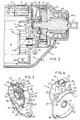
- the hammer drill shown in Fig. 1 is of generally conventional shape. It comprises a housing 1 of 2-part clam-shell construction formed with a handle 2, a body part 3 and a nose part 4. Mounted in the handle is a trigger 5 that operates an ON/OFF switch which controls the power supply to an electric motor indicated by dotted lines 6 accommodated in the body part 3. Extending from the nose part 4 is an output shaft 7 carrying a chuck 8.
- the motor 6 is supported within the body part 3 by ribs formed on the internal faces of the clam shells.
- the body part 3 is separated from the nose part 4 by an internal gear case rear partition formed as a metal casting and described in more detail below.
- the nose portion 4 accommodates reduction gears which reduce the motor speed to a desired chuck speed.
- the reduction gears are housed within a gear case formed by the gear case rear partition and a gear case cover which fits against the partition and will be described in more detail below.
- a mode change mechanism mounted upon the gear case rear partition is a mode change mechanism that will be described in more detail below and which enables the drill to be used in a hammer or a non-hammer mode.
- the mechanism is operated by an actuator 9 located in a recess 10 formed in the adjoining upper surfaces of the clam shells.
- the gear case rear partition 11 is shown in perspective in Figs. 3 and 4. It is a metal casting whose lower part 12 is of plate-like form.
- the upper part 13 is of shallow cup-like form, the base of the cup overlapping slightly the front face of the part 12.
- the part 12 is formed with a central sleeve 14 that extends outwardly from both faces of the part.
- the sleeve 14 accommodates a needle bearing 14a (Fig. 2) which supports the forward end part of the armature shaft 15 of the motor 6.
- the forward end of the shaft is machined to form a pinion 16.
- a sleeve 20 Centrally located within the part 13 is a sleeve 20 which extends from a raised portion 21 of the floor 22 of the part 13.
- the portion 21 is of generally rectangular form when seen in elevation as in Fig. 5, its upper part 23 being inclined forwardly as seen in Fig. 8.
- the bore of the sleeve 20 opens into the pocket 24.
- the open end of the pocket lies in the curved wall of the cup-shaped part 13.
- the rear face of the floor 22 of the part 13 has an external diametral stiffening rib 25 of T-shape, there being a small stud 26 located on the horizontal arm of the T as seen in Fig. 4.
- bosses 27 equi-spaced round the curved wall of the part 13 each have a central passage 28 closed at its inner end. Additional screw holes 29 in the base 22 extend through ears 30 on the upper edge of part 12.
- ribs 31 that extend radially outwards from the sleeve 20. These ribs form a key for a fixed ratchet 32 of a ratchet mechanism that provides the hammer action.
- the fixed ratchet has a central bore 33 therein of a size such that it can be pressed onto the outside of the sleeve 20 to locate the fixed ratchet.
- the fixed ratchet 32 is shown in detail in Figs. 9, 10 and 11, and is formed of metal and its central bore 33 accommodates that part 34 of the sleeve 20 that projects outwardly beyond the plane of the ribs 31.
- the bore 33 is stepped as at 35 (see Fig. 10), the step seating upon the end face of the sleeve 20.
- the fixed ratchet 32 On one circular face, the fixed ratchet 32 has a series of projections 36 equi-spaced round the periphery of the face which are dimensioned and spaced so that they fit between the ribs 31. The fixed ratchet 32 cannot therefore rotate relative to the partition 11.
- the fixed ratchet 32 On its other circular face, the fixed ratchet 32 has a series of spaced radially-extending teeth 37 each of which has inclined faces 38, 39. Faces 38 are inclined more sharply than faces 39 as can be seen from Fig. 10.
- a rotary ratchet gear 40 secured to the inner end of the output shaft 7 and rotatable therewith as can be seen in Fig. 2.
- the periphery of ratchet gear 40 has teeth 41 which mesh with pinion 16 referred to above.
- One circular face of the rotary ratchet gear 40 is formed with radial ratchet teeth 42 of a configuration similar to that of teeth 37 on the fixed ratchet 32.
- the inner end of the shaft 7 is rotatably supported in a plain bearing 43 located in sleeve 20 and, as can be seen from Fig. 2, the inner end of the shaft protrudes into the open-topped pocket 24.
- the outer end of the shaft 7 is rotatably supported in a plain bearing 43a accommodated in a sleeve 44 which projects forwardly of a gear box front wall 45.
- the wall 45 is contoured, as seen in Fig. 2, to accommodate the fixed and rotatable ratchets 32, 40 and the pinion 16.
- the front wall 45 has an inner edge 46 that seats against a stepped edge 47 of the casting and formed round the curved wall of the cup-like part 13 of the partition 11.
- the front wall 45 is secured to the partition 11 by screws which pass through holes in the front wall that are aligned with the bosses 27 and which screw into the passages 28 in those bosses.
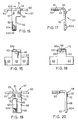
- the actuator 9 shown in Figs. 12, 13 and 14 is a moulded plastics component (e.g. of ABS) of generally rectangular form when seen in plan as in fig. 12.
- the actuator has a transverse groove 50 across its central area and arms 51 that incline downwardly slightly as can be seen in Fig. 13.
- the upper surfaces - those seen in Fig. 12 - of the arms 51 are recessed centrally as indicated at 52 to facilitate actuation thereof by a user.
- Extending downwardly from the ends of the arms 51 are tips 53 which extend across the full width of the arms.
- Each arm 51 also carries a prong 54 that extends away from the arm in the same direction as the tips 53.
- the ends of the prongs 54 are out-turned as indicated at 55. As can be seen in Fig. 21, these out-turned end 55 locate in detent grooves 56, 57, in the clam shell, to hold the actuator either in a hammer or a non-hammer mode, depending on which way it is rocked
- a transverse spindle 56 Formed integrally with the actuator 9 and on the undersurface thereof is a transverse spindle 56 by means of which the actuator 9 is pivotally mounted in the clam shell halves.
- a thrust plate assembly comprising a thrust plate 57 and a leaf spring 58 shown in Figs. 18, 19 and 20.
- the thrust plate 57 shown in Figs. 15, 16 and 17 is made from steel plate and is of generally T-shape when seen in end view as in Fig. 16.
- the head 59 of the plate 57 is generally rectangular as shown in Fig. 15, the limbs 60 of the head being inclined downwardly slightly from a flat central area 61. The inclination corresponds with that of the arms 51 of the actuator 9.
- the vertical limb 62 of the thrust plate 57 is part of a central extension 63 of the area 61 and is cut away as indicated at 64 to receive the leaf spring as will be described below in more detail. At its free end, it is thickened up by a pressing operation to provide a radiused, projecting stud or pad 62a.
- the extension 63 has a rectangular hole 65 in it, and there is a circular hole 66 in the limb 62 immediately above the cut-away part 64.
- a small stud 67 located adjacent to the hole 66 forms a location pin for the leaf spring shown in figs. 18, 19 and 20.
- the leaf spring 58 is made of thin spring steel and is of elongate form having a portion 68 sized to correspond with the cut away 64 and a portion 69 whose width approximates to that of the upper part of the limb 62 of the thrust plate 57.
- the portion 69 is slotted as at 70 and adjacent the slot is a circular hole 71.
- the spring is slid over the surface of the plate to engage the stud 67 in the slot 70 and to align the hole 66 in the limb 62 with the hole 71.
- the spring is then secured to the thrust plate by a rivet 72 passed through the holes 71 and 66 from right to left as viewed in Fig. 20.
- the thickness of the limb 62 is considerable as compared with that of the leaf spring 58 and thus the leaf spring is able to flex within the depth of the cut-away portion 64 of the thrust plate.
- the assembly shown in Figs. 18, 19 and 20 is inserted into the pocket 24, the limb 62 and spring 68 entering first.
- the stud 26 locates loosely in the hole 65 so pivotally mounting the assembly.
- the limb 62 and spring 58 lie closely adjacent to the floor 22 of the part 13 of the partition.
- the actuator 9 is then placed over the assembly (see Fig. 21) so that the head 59 and limbs 60 are located beneath the arms 51 of the actuator head, the prongs 54 lying externally of the assembly and of the inclined part 23 of partition 21 of the pocket, with the out-turned ends 55 in contact with the rear face of the floor 22 thereby acting to guide the actuator during movement.
- the ends of the spindle 56 on the actuator 9 locate in bearing slots in the clam shell halves.
- the mode change mechanism is thus pivotable by a user between the position shown in Fig. 21 in which the pad 62a on the limb 62 of the thrust plate lies directly behind the sleeve 20 in the part 13 of the rear wall 11 and a position in which the leaf spring 58 lies behind that sleeve.
- the output shaft 7 is movable axially over a short distance and is shown in its rearward position in Fig. 2. In that position, the teeth 37 on the fixed ratchet 32 are in engagement with the teeth 42 on the movable ratchet 40 secured to the output shaft 7. In moving rearwardly, the shaft 7 has flexed the leaf spring rearwardly into the cut-away 64.
- the output shaft 7 In its forward position, the output shaft 7 is so located that the teeth on the movable ratchet 40 are out of contact with the teeth on the fixed ratchet 32.
- the mode change mechanism is operated to the position in which the pad 62a on the limb 62 of the thrust plate lies directly behind the inner end of the output shaft 7 and prevents rearward movement of the latter. That position of the mode change mechanism is the non-hammer or drill only position.
- the floor 22 of the part 13 supports the limb 62 when the drill, is in non-hammer mode use and this provides an improved resistance to axial movement of the spindle.
- a fan 73 which, in use, circulates cooling air through the motor 6 in a well-known manner.
- the output of the fan 73 is confined to some extent by the arcuate walls 17, 18 referred to above and directed thereby to atmosphere via vents in the clam shells.
- One of the vents is shown at 74 in Fig. 1.
- the walls 17, (18) also assist to locate the motor, and are designed to draw heat away from the ratchet area of casting, especially the top wall 17. it is important to cool the casting, as it gets very hot when the drill is being used in hammer mode.
- the walls also serve to strengthen the rear wall 12 of the casting. This is important to ensure the casting does not break if the drill should be dropped on its chuck.
Description
- This invention relates to power drills.
- Swiss patent specification CH-A-467 143 discloses a power drill including an output shaft with a tool bit holder at the outer end of the shaft, bearings for supporting the shaft for rotary and limited axial movement, and a mode change mechanism for changing the operating condition of the drill between a non-hammer mode and a hammer mode, the mode change mechanism comprising a first rigid member and a second resilient member.
- According to the present invention, we provide a power drill including an output shaft with a tool bit holder at the outer end of the shaft, bearings for supporting the shaft for rotary and limited axial movement, and a mode change mechanism for changing the operating condition of the drill between a non-hammer mode and a hammer mode, the mode change mechanism comprising a first rigid member and a second resilient member, characterised in that the members are carried by a common support movable between a first position in which the rigid member is aligned with the output shaft to prevent axial movement of the shaft and a second position in which the resilient member is aligned with the output shaft to allow axial movement of the shaft.
- Preferably, the common support is mounted upon an internal partition of the drill, and which the first rigid member is supported against rearward movement by the partition when the common support is in its first position.
- Preferably, the internal partition comprises a mounting for a fixed ratchet member, and a bearing in which one end of the output shaft is rotatably supported, the shaft carrying a second ratchet member cooperable with the first ratchet member to oscillate the shaft along its axis when the drill is operating in the hammer mode.
- Preferably, the internal partition includes a pocket, the first rigid member and the second resilient member being located in the pocket, and one end of the output shaft projects into the pocket. The common support is preferably pivotally mounted upon the internal partition. It is preferred that the common support is of T-shape, with the vertical limb of the T being of two-part construction, of which one part is the first rigid member and the second part is the second resilient member.
- Preferably, the second resilient member is a leaf spring secured to the common support in side-by-side relationship with the first rigid member.
- The internal partition may be one wall of an enclosure which houses the first and second ratchet members. It is also preferred that the drill drive motor has an armature shaft rotatably supported at one end in a bearing carried by the internal partition.
- By way of example only, a hammer drill embodying the invention will now be described in greater detail with reference to the accompanying drawings, in which:
- Fig. 1 is a perspective view of the drill,
- Fig. 2 is a section in a vertical plane through the front part only of the drill shown in Fig. 1, without the drill chuck,
- Figs. 3 and 4 are front and rear perspective views of a component of the drill,
- Figs. 5 and 6 are, respectively, a front and side elevation of the component of Figs. 3 and 4,
- Fig. 7 is a section on the line VII-VII of Fig. 6,
- Fig. 8 is a section on the line VIII-VIII of Fig. 5,
- Fig. 9 is a front view of another component of the drill,
- Fig. 10 is a section on the line X-X of Fig. 9,
- Fig. 11 is a rear view of the component of Fig. 9,
- Figs. 12, 13 and 14 are, respectively, plan view, end view, and underneath view of a further component,
- Figs. 15, 16 and 17 are, respectively, plan view, end view, and section on line XVII-XVII of Fig. 16 of a further part,
- Figs. 18, 19 and 20 are, respectively, plan view, end view and side view of an assembly of parts, and
- Fig. 21 is a section on a larger scale through the drill on a vertical plane represented by the line XXI-XXI of Fig. 1.
- The hammer drill shown in Fig. 1 is of generally conventional shape. It comprises a housing 1 of 2-part clam-shell construction formed with a
handle 2, abody part 3 and anose part 4. Mounted in the handle is atrigger 5 that operates an ON/OFF switch which controls the power supply to an electric motor indicated bydotted lines 6 accommodated in thebody part 3. Extending from thenose part 4 is anoutput shaft 7 carrying achuck 8. - The
motor 6 is supported within thebody part 3 by ribs formed on the internal faces of the clam shells. Thebody part 3 is separated from thenose part 4 by an internal gear case rear partition formed as a metal casting and described in more detail below. Thenose portion 4 accommodates reduction gears which reduce the motor speed to a desired chuck speed. The reduction gears are housed within a gear case formed by the gear case rear partition and a gear case cover which fits against the partition and will be described in more detail below. - Mounted upon the gear case rear partition is a mode change mechanism that will be described in more detail below and which enables the drill to be used in a hammer or a non-hammer mode. The mechanism is operated by an
actuator 9 located in arecess 10 formed in the adjoining upper surfaces of the clam shells. - The gear case
rear partition 11 is shown in perspective in Figs. 3 and 4. It is a metal casting whoselower part 12 is of plate-like form. Theupper part 13 is of shallow cup-like form, the base of the cup overlapping slightly the front face of thepart 12. - The
part 12 is formed with acentral sleeve 14 that extends outwardly from both faces of the part. Thesleeve 14 accommodates a needle bearing 14a (Fig. 2) which supports the forward end part of thearmature shaft 15 of themotor 6. The forward end of the shaft is machined to form apinion 16. - Extending from the rear face of the
part 12 are upper and lowerarcuate walls holes 19 in the lower corners of thepart 12 are provided for screws which secure the partition to bosses formed on the inside faces of the clam shells. - Centrally located within the
part 13 is asleeve 20 which extends from a raisedportion 21 of thefloor 22 of thepart 13. Theportion 21 is of generally rectangular form when seen in elevation as in Fig. 5, itsupper part 23 being inclined forwardly as seen in Fig. 8. There is thus formed an open-topped pocket 24 between theportion 21 and thefloor 22. As can be seen from Fig. 8, the bore of thesleeve 20 opens into thepocket 24. The open end of the pocket lies in the curved wall of the cup-shaped part 13. The rear face of thefloor 22 of thepart 13 has an external diametralstiffening rib 25 of T-shape, there being asmall stud 26 located on the horizontal arm of the T as seen in Fig. 4. - Four
bosses 27 equi-spaced round the curved wall of thepart 13 each have acentral passage 28 closed at its inner end.Additional screw holes 29 in thebase 22 extend throughears 30 on the upper edge ofpart 12. - Formed in the front face of the
portion 21 areribs 31 that extend radially outwards from thesleeve 20. These ribs form a key for afixed ratchet 32 of a ratchet mechanism that provides the hammer action. The fixed ratchet has acentral bore 33 therein of a size such that it can be pressed onto the outside of thesleeve 20 to locate the fixed ratchet. - The
fixed ratchet 32 is shown in detail in Figs. 9, 10 and 11, and is formed of metal and itscentral bore 33 accommodates thatpart 34 of thesleeve 20 that projects outwardly beyond the plane of theribs 31. Thebore 33 is stepped as at 35 (see Fig. 10), the step seating upon the end face of thesleeve 20. - On one circular face, the
fixed ratchet 32 has a series ofprojections 36 equi-spaced round the periphery of the face which are dimensioned and spaced so that they fit between theribs 31. Thefixed ratchet 32 cannot therefore rotate relative to thepartition 11. - On its other circular face, the
fixed ratchet 32 has a series of spaced radially-extendingteeth 37 each of which has inclinedfaces Faces 38 are inclined more sharply thanfaces 39 as can be seen from Fig. 10. - Cooperating with the
fixed ratchet 32 is arotary ratchet gear 40 secured to the inner end of theoutput shaft 7 and rotatable therewith as can be seen in Fig. 2. The periphery ofratchet gear 40 hasteeth 41 which mesh withpinion 16 referred to above. One circular face of therotary ratchet gear 40 is formed withradial ratchet teeth 42 of a configuration similar to that ofteeth 37 on thefixed ratchet 32. - The inner end of the
shaft 7 is rotatably supported in a plain bearing 43 located insleeve 20 and, as can be seen from Fig. 2, the inner end of the shaft protrudes into the open-topped pocket 24. - The outer end of the
shaft 7 is rotatably supported in a plain bearing 43a accommodated in asleeve 44 which projects forwardly of a gearbox front wall 45. Thewall 45 is contoured, as seen in Fig. 2, to accommodate the fixed androtatable ratchets pinion 16. Thefront wall 45 has aninner edge 46 that seats against a steppededge 47 of the casting and formed round the curved wall of the cup-like part 13 of thepartition 11. - The
front wall 45 is secured to thepartition 11 by screws which pass through holes in the front wall that are aligned with thebosses 27 and which screw into thepassages 28 in those bosses. - Accommodated within the
pocket 24 is a mode change mechanism actuable by theactuator 9 referred to above. - The
actuator 9 shown in Figs. 12, 13 and 14 is a moulded plastics component (e.g. of ABS) of generally rectangular form when seen in plan as in fig. 12. The actuator has atransverse groove 50 across its central area andarms 51 that incline downwardly slightly as can be seen in Fig. 13. The upper surfaces - those seen in Fig. 12 - of thearms 51 are recessed centrally as indicated at 52 to facilitate actuation thereof by a user. Extending downwardly from the ends of thearms 51 aretips 53 which extend across the full width of the arms. Eacharm 51 also carries aprong 54 that extends away from the arm in the same direction as thetips 53. The ends of theprongs 54 are out-turned as indicated at 55. As can be seen in Fig. 21, these out-turnedend 55 locate indetent grooves - Formed integrally with the
actuator 9 and on the undersurface thereof is atransverse spindle 56 by means of which theactuator 9 is pivotally mounted in the clam shell halves. - Positioned below the
actuator 9 is a thrust plate assembly comprising athrust plate 57 and aleaf spring 58 shown in Figs. 18, 19 and 20. - The
thrust plate 57 shown in Figs. 15, 16 and 17 is made from steel plate and is of generally T-shape when seen in end view as in Fig. 16. Thehead 59 of theplate 57 is generally rectangular as shown in Fig. 15, thelimbs 60 of the head being inclined downwardly slightly from a flatcentral area 61. The inclination corresponds with that of thearms 51 of theactuator 9. - The
vertical limb 62 of thethrust plate 57 is part of acentral extension 63 of thearea 61 and is cut away as indicated at 64 to receive the leaf spring as will be described below in more detail. At its free end, it is thickened up by a pressing operation to provide a radiused, projecting stud orpad 62a. Theextension 63 has arectangular hole 65 in it, and there is acircular hole 66 in thelimb 62 immediately above the cut-awaypart 64. Asmall stud 67 located adjacent to thehole 66 forms a location pin for the leaf spring shown in figs. 18, 19 and 20. - The
leaf spring 58 is made of thin spring steel and is of elongate form having aportion 68 sized to correspond with the cut away 64 and aportion 69 whose width approximates to that of the upper part of thelimb 62 of thethrust plate 57. - The
portion 69 is slotted as at 70 and adjacent the slot is acircular hole 71. - To mount the
leaf spring 58 on thethrust plate 57, the spring is slid over the surface of the plate to engage thestud 67 in theslot 70 and to align thehole 66 in thelimb 62 with thehole 71. The spring is then secured to the thrust plate by arivet 72 passed through theholes - As can be seen from Fig. 20, the thickness of the
limb 62 is considerable as compared with that of theleaf spring 58 and thus the leaf spring is able to flex within the depth of the cut-awayportion 64 of the thrust plate. - To mount the mode change mechanism, the assembly shown in Figs. 18, 19 and 20 is inserted into the
pocket 24, thelimb 62 andspring 68 entering first. Thestud 26 locates loosely in thehole 65 so pivotally mounting the assembly. When so mounted, thelimb 62 andspring 58 lie closely adjacent to thefloor 22 of thepart 13 of the partition. - The
actuator 9 is then placed over the assembly (see Fig. 21) so that thehead 59 andlimbs 60 are located beneath thearms 51 of the actuator head, theprongs 54 lying externally of the assembly and of theinclined part 23 ofpartition 21 of the pocket, with the out-turned ends 55 in contact with the rear face of thefloor 22 thereby acting to guide the actuator during movement. The ends of thespindle 56 on theactuator 9 locate in bearing slots in the clam shell halves. - The mode change mechanism is thus pivotable by a user between the position shown in Fig. 21 in which the
pad 62a on thelimb 62 of the thrust plate lies directly behind thesleeve 20 in thepart 13 of therear wall 11 and a position in which theleaf spring 58 lies behind that sleeve. - As is conventional in hammer drills, the
output shaft 7 is movable axially over a short distance and is shown in its rearward position in Fig. 2. In that position, theteeth 37 on the fixedratchet 32 are in engagement with theteeth 42 on themovable ratchet 40 secured to theoutput shaft 7. In moving rearwardly, theshaft 7 has flexed the leaf spring rearwardly into the cut-away 64. - In its forward position, the
output shaft 7 is so located that the teeth on themovable ratchet 40 are out of contact with the teeth on the fixedratchet 32. To maintain the output shaft in that forward position when the drill is in use, the mode change mechanism is operated to the position in which thepad 62a on thelimb 62 of the thrust plate lies directly behind the inner end of theoutput shaft 7 and prevents rearward movement of the latter. That position of the mode change mechanism is the non-hammer or drill only position. - When the mode change mechanism is rocked to its other position in which the
leaf spring 58 lies directly behind the inner end of theoutput shaft 7, the latter is allowed to move rearwardly against the resilient action of theleaf spring 58 which flexes backwardly into the cut away 64 as is explained above. - It will be appreciated that the
floor 22 of thepart 13 supports thelimb 62 when the drill, is in non-hammer mode use and this provides an improved resistance to axial movement of the spindle. - Mounted upon the
armature shaft 15 adjacent to thepartition 11 is afan 73 which, in use, circulates cooling air through themotor 6 in a well-known manner. The output of thefan 73 is confined to some extent by thearcuate walls walls 17, (18) also assist to locate the motor, and are designed to draw heat away from the ratchet area of casting, especially thetop wall 17. it is important to cool the casting, as it gets very hot when the drill is being used in hammer mode. The walls also serve to strengthen therear wall 12 of the casting. This is important to ensure the casting does not break if the drill should be dropped on its chuck.
Claims (11)
- A power drill including an output shaft (7) with a tool bit holder (chuck) (8), at the outer end of the shaft (7), bearings (43,43a) for supporting the shaft (7) for rotary and limited axial movement, and a mode change mechanism for changing the operating condition of the drill between a non-hammer mode and a hammer mode, the mode change mechanism comprising a first rigid member (62) and a second resilient member (58), characterised in that the members (62,58) are carried by a common support (61) movable between a first position in which the rigid member (62) is aligned with the output shaft (7) to prevent axial movement of the shaft and a second position in which the resilient member (58) is aligned with the output shaft (7) to allow axial movement of the shaft.
- A power drill as claimed in Claim 1 in which the common support (61) is mounted upon an internal partition (22) of the drill, and in which the first rigid member (62) is supported against rearward movement by the partition (22) when the common support (61) is in its first position.
- A power drill as claimed in Claim 2 in which the internal partition (22) comprises a mounting (34) for a fixed ratchet member (33), and a bearing (43) in which one end of the output shaft (7) is rotatably supported, the shaft (7) carrying a second ratchet member (32) cooperable with the first ratchet member (33) to oscillate the shaft (7) along its axis when the drill is operating in the hammer mode.
- A power drill as claimed in Claim 3 in which the internal partition (22) includes a pocket (24), the being located in the pocket (28), and in which one end of the output shaft (7) projects into the pocket (24).
- A power drill as claimed in any one of Claims 1 to 4 in which the common support (61) is pivotally mounted upon the internal partition (22).
- A power drill as claimed in Claim 5 in which the common support (61) is of T-shape, the vertical limb of the T being of two-part construction, of which one part is the first rigid member (62) and the second part is the second resilient member (58).
- A power drill as claimed in Claim 6 in which the second resilient member (58) is a leaf spring secured to the common support (61) in side-by-side relationship with the first rigid member (62).
- A power drill as claimed in Claim 7 in which the internal partition (22) is one wall of an enclosure which houses the first and second ratchet members (33,32).
- A power drill as claimed in Claim 8 in which the drill drive motor (6) has an armature shaft (15)rotatably supported at one end in a bearing (14a) carried by the internal partition (22).
- A power drill as claimed in Claim 9 in which the second ratchet member (32) is a ratchet gear (40) and in which the one end of the armature shaft (15) has a pinion (16) in driving engagement with the ratchet gear (40).
- A power drill as claimed in any one of the preceding claims in which a pad (62a) is provided on the rigid member (62) for alignment with the output shaft (7).
Applications Claiming Priority (2)
| Application Number | Priority Date | Filing Date | Title |
|---|---|---|---|
| GB8912066A GB2232372A (en) | 1989-05-25 | 1989-05-25 | Improvements in or relating to power tools |
| GB8912066 | 1989-05-25 |
Publications (3)
| Publication Number | Publication Date |
|---|---|
| EP0399714A2 EP0399714A2 (en) | 1990-11-28 |
| EP0399714A3 EP0399714A3 (en) | 1991-05-08 |
| EP0399714B1 true EP0399714B1 (en) | 1994-07-27 |
Family
ID=10657351
Family Applications (1)
| Application Number | Title | Priority Date | Filing Date |
|---|---|---|---|
| EP90305188A Expired - Lifetime EP0399714B1 (en) | 1989-05-25 | 1990-05-15 | Improvements in or relating to power tools |
Country Status (4)
| Country | Link |
|---|---|
| US (1) | US5056607A (en) |
| EP (1) | EP0399714B1 (en) |
| DE (1) | DE69010990T2 (en) |
| GB (1) | GB2232372A (en) |
Cited By (8)
| Publication number | Priority date | Publication date | Assignee | Title |
|---|---|---|---|---|
| EP1834736A1 (en) | 2006-03-18 | 2007-09-19 | Metabowerke GmbH | Hand power tool |
| US7717192B2 (en) | 2007-11-21 | 2010-05-18 | Black & Decker Inc. | Multi-mode drill with mode collar |
| US7717191B2 (en) | 2007-11-21 | 2010-05-18 | Black & Decker Inc. | Multi-mode hammer drill with shift lock |
| US7735575B2 (en) | 2007-11-21 | 2010-06-15 | Black & Decker Inc. | Hammer drill with hard hammer support structure |
| US7762349B2 (en) | 2007-11-21 | 2010-07-27 | Black & Decker Inc. | Multi-speed drill and transmission with low gear only clutch |
| US7770660B2 (en) | 2007-11-21 | 2010-08-10 | Black & Decker Inc. | Mid-handle drill construction and assembly process |
| US7798245B2 (en) | 2007-11-21 | 2010-09-21 | Black & Decker Inc. | Multi-mode drill with an electronic switching arrangement |
| US7854274B2 (en) | 2007-11-21 | 2010-12-21 | Black & Decker Inc. | Multi-mode drill and transmission sub-assembly including a gear case cover supporting biasing |
Families Citing this family (35)
| Publication number | Priority date | Publication date | Assignee | Title |
|---|---|---|---|---|
| JP2820323B2 (en) * | 1990-12-18 | 1998-11-05 | エルム株式会社 | Electric stapler |
| GB2275644B (en) * | 1993-03-05 | 1995-12-13 | Black & Decker Inc | Chuck spindle device and power tools incorporating same |
| GB9304540D0 (en) * | 1993-03-05 | 1993-04-21 | Black & Decker Inc | Power tool and mechanism |
| DE19527117C2 (en) * | 1995-07-25 | 2000-05-31 | Metabowerke Kg | Hand drill with device for switching the operating modes "drilling" and "hammer drilling" |
| CH692658A5 (en) * | 1996-06-15 | 2002-09-13 | Bosch Gmbh Robert | Electric combination hammer. |
| JP3911905B2 (en) * | 1999-04-30 | 2007-05-09 | 松下電工株式会社 | Impact rotary tool |
| GB0008465D0 (en) * | 2000-04-07 | 2000-05-24 | Black & Decker Inc | Rotary hammer mode change mechanism |
| DE10027392B4 (en) * | 2000-06-02 | 2005-08-18 | Metabowerke Gmbh | impact drill |
| DE10031050A1 (en) * | 2000-06-26 | 2002-01-10 | Hilti Ag | Hand tool |
| GB0111535D0 (en) * | 2001-05-11 | 2001-07-04 | Johnson Electric Sa | Gear motor for power tool |
| AU2002326946A1 (en) * | 2001-09-17 | 2003-04-01 | Milwaukee Electric Tool Corporation | Rotary hammer |
| GB0214772D0 (en) * | 2002-06-26 | 2002-08-07 | Black & Decker Inc | Hammer |
| DE10240361A1 (en) * | 2002-09-02 | 2004-03-11 | Hilti Ag | Rotating and striking electric hand machine tool |
| JP4075540B2 (en) * | 2002-09-10 | 2008-04-16 | 松下電工株式会社 | Electric tool |
| TW554792U (en) | 2003-01-29 | 2003-09-21 | Mobiletron Electronics Co Ltd | Function switching device of electric tool |
| TW556637U (en) | 2003-02-24 | 2003-10-01 | Mobiletron Electronics Co Ltd | Power tool |
| DE10326472B4 (en) * | 2003-06-12 | 2006-03-09 | Hilti Ag | Connecting element for connecting a handle with a housing part and a transmission housing of a hand-held electrical device |
| JP4084319B2 (en) * | 2004-02-23 | 2008-04-30 | リョービ株式会社 | Electric tool |
| JP4400303B2 (en) * | 2004-05-12 | 2010-01-20 | パナソニック電工株式会社 | Impact rotary tool |
| DE102004030313B4 (en) * | 2004-06-23 | 2019-10-31 | Robert Bosch Gmbh | Hand tool |
| US7308948B2 (en) | 2004-10-28 | 2007-12-18 | Makita Corporation | Electric power tool |
| EP1674207B1 (en) | 2004-12-23 | 2008-12-10 | BLACK & DECKER INC. | Power tool |
| GB0428210D0 (en) * | 2004-12-23 | 2005-01-26 | Black & Decker Inc | Mode change mechanism |
| JP4643298B2 (en) | 2005-02-14 | 2011-03-02 | 株式会社マキタ | Impact tool |
| US20060213675A1 (en) * | 2005-03-24 | 2006-09-28 | Whitmire Jason P | Combination drill |
| US7410007B2 (en) * | 2005-09-13 | 2008-08-12 | Eastway Fair Company Limited | Impact rotary tool with drill mode |
| JP4812471B2 (en) * | 2006-03-09 | 2011-11-09 | 株式会社マキタ | Work tools |
| US20070227310A1 (en) * | 2006-03-31 | 2007-10-04 | Heiko Roehm | Hand power tool |
| JP4605242B2 (en) * | 2008-04-10 | 2011-01-05 | パナソニック電工株式会社 | Electric tool |
| JP5477759B2 (en) * | 2008-07-30 | 2014-04-23 | 日立工機株式会社 | Electric tool |
| US8584770B2 (en) | 2010-03-23 | 2013-11-19 | Black & Decker Inc. | Spindle bearing arrangement for a power tool |
| DE102010041045A1 (en) * | 2010-09-20 | 2012-03-22 | Robert Bosch Gmbh | Hand tool machine, in particular percussion drill |
| US10328560B2 (en) | 2015-02-23 | 2019-06-25 | Brian Romagnoli | Multi-mode drive mechanisms and tools incorporating the same |
| US10654114B2 (en) * | 2018-06-08 | 2020-05-19 | Lockheed Martin Corporation | Micro-peck feed drill clutch |
| JP7246202B2 (en) * | 2019-02-19 | 2023-03-27 | 株式会社マキタ | Power tool with vibration mechanism |
Family Cites Families (10)
| Publication number | Priority date | Publication date | Assignee | Title |
|---|---|---|---|---|
| CA684169A (en) * | 1957-10-10 | 1964-04-14 | J. Gapstur John | Selective drilling and percussion assembly |
| US3006202A (en) * | 1958-03-17 | 1961-10-31 | Samuel J Forbes | Rotary and percussive tool |
| DE1652504A1 (en) * | 1967-09-09 | 1970-10-22 | Mey Kg Maschf Mafell | Electric motor-driven hammer drill |
| GB1432369A (en) * | 1972-07-13 | 1976-04-14 | Black & Decker Ltd | Hammer drill mechanism |
| DE2557118C2 (en) * | 1975-12-18 | 1984-01-12 | C. & E. Fein Gmbh & Co, 7000 Stuttgart | Portable rotary impact machines with detachable striking mechanism |
| DE2715682C3 (en) * | 1977-04-07 | 1982-05-27 | Metabowerke KG Closs, Rauch & Schnizler, 7440 Nürtingen | Impact drill with notches fixed to the housing |
| DE2747537A1 (en) * | 1977-10-22 | 1979-04-26 | Scintilla Ag | DRILLING MACHINE SWITCHABLE TO ROTARY DRILLING AND IMPACT DRILLING |
| DE3115419C2 (en) * | 1981-04-16 | 1985-03-07 | Licentia Patent-Verwaltungs-Gmbh, 6000 Frankfurt | Impact drill with a device for switching from rotary drilling to hammer drilling |
| US4489792A (en) * | 1981-05-28 | 1984-12-25 | Fahim Atef E F | Hammer drill adapter |
| JPS5969808U (en) * | 1982-09-07 | 1984-05-11 | 株式会社マキタ | Vibratory device in vibrating drill |
-
1989
- 1989-05-25 GB GB8912066A patent/GB2232372A/en not_active Withdrawn
-
1990
- 1990-05-14 US US07/523,225 patent/US5056607A/en not_active Expired - Lifetime
- 1990-05-15 EP EP90305188A patent/EP0399714B1/en not_active Expired - Lifetime
- 1990-05-15 DE DE69010990T patent/DE69010990T2/en not_active Expired - Fee Related
Cited By (11)
| Publication number | Priority date | Publication date | Assignee | Title |
|---|---|---|---|---|
| EP1834736A1 (en) | 2006-03-18 | 2007-09-19 | Metabowerke GmbH | Hand power tool |
| US7717192B2 (en) | 2007-11-21 | 2010-05-18 | Black & Decker Inc. | Multi-mode drill with mode collar |
| US7717191B2 (en) | 2007-11-21 | 2010-05-18 | Black & Decker Inc. | Multi-mode hammer drill with shift lock |
| US7735575B2 (en) | 2007-11-21 | 2010-06-15 | Black & Decker Inc. | Hammer drill with hard hammer support structure |
| US7762349B2 (en) | 2007-11-21 | 2010-07-27 | Black & Decker Inc. | Multi-speed drill and transmission with low gear only clutch |
| US7770660B2 (en) | 2007-11-21 | 2010-08-10 | Black & Decker Inc. | Mid-handle drill construction and assembly process |
| US7798245B2 (en) | 2007-11-21 | 2010-09-21 | Black & Decker Inc. | Multi-mode drill with an electronic switching arrangement |
| US7854274B2 (en) | 2007-11-21 | 2010-12-21 | Black & Decker Inc. | Multi-mode drill and transmission sub-assembly including a gear case cover supporting biasing |
| US7987920B2 (en) | 2007-11-21 | 2011-08-02 | Black & Decker Inc. | Multi-mode drill with mode collar |
| US8109343B2 (en) | 2007-11-21 | 2012-02-07 | Black & Decker Inc. | Multi-mode drill with mode collar |
| US8555998B2 (en) | 2007-11-21 | 2013-10-15 | Black & Decker Inc. | Multi-mode drill with mode collar |
Also Published As
| Publication number | Publication date |
|---|---|
| DE69010990T2 (en) | 1994-11-17 |
| DE69010990D1 (en) | 1994-09-01 |
| GB2232372A (en) | 1990-12-12 |
| US5056607A (en) | 1991-10-15 |
| GB8912066D0 (en) | 1989-07-12 |
| EP0399714A3 (en) | 1991-05-08 |
| EP0399714A2 (en) | 1990-11-28 |
Similar Documents
| Publication | Publication Date | Title |
|---|---|---|
| EP0399714B1 (en) | Improvements in or relating to power tools | |
| US6263980B1 (en) | Power tool | |
| US7748123B2 (en) | Electric hair cutting appliance with counter weight | |
| EP0147134B1 (en) | Electric hair clipper | |
| US6189217B1 (en) | Power saw having blade storage chamber | |
| WO2001058628A1 (en) | Accessory tray for a hand-held power tool | |
| CN103862440A (en) | Power tool system | |
| JP5774383B2 (en) | CUTTING MACHINE COVER DEVICE AND CUTTING MACHINE WITH CUTTING COVER COVER DEVICE | |
| JP3769957B2 (en) | Hair cutter | |
| EP1731278B1 (en) | Biscuit Joiner | |
| JP2004001363A (en) | Electromotive cutting machine | |
| KR20040078642A (en) | Electrical working machine | |
| US20230311291A1 (en) | Rotary tool | |
| US6185826B1 (en) | Electric slicing knife with switch guard | |
| US5771580A (en) | Electric razor | |
| US5225727A (en) | Reverse switch assembly | |
| US4916770A (en) | Portable electric shoe shiner | |
| CN102666044B (en) | There is the electric tool of depth adjusting mechanism | |
| US4242799A (en) | Car shaver and holder therefor | |
| JP3651086B2 (en) | Portable cutting tool | |
| CN220029728U (en) | Small-sized angle grinder | |
| US20220168830A1 (en) | Reciprocating tool | |
| US3818778A (en) | Mounting assembly for a shaft of a power tool | |
| JPS6130615Y2 (en) | ||
| JPH0121654Y2 (en) |
Legal Events
| Date | Code | Title | Description |
|---|---|---|---|
| PUAI | Public reference made under article 153(3) epc to a published international application that has entered the european phase |
Free format text: ORIGINAL CODE: 0009012 |
|
| AK | Designated contracting states |
Kind code of ref document: A2 Designated state(s): CH DE FR GB IT LI |
|
| PUAL | Search report despatched |
Free format text: ORIGINAL CODE: 0009013 |
|
| AK | Designated contracting states |
Kind code of ref document: A3 Designated state(s): CH DE FR GB IT LI |
|
| 17P | Request for examination filed |
Effective date: 19911011 |
|
| 17Q | First examination report despatched |
Effective date: 19930303 |
|
| GRAA | (expected) grant |
Free format text: ORIGINAL CODE: 0009210 |
|
| AK | Designated contracting states |
Kind code of ref document: B1 Designated state(s): CH DE FR GB IT LI |
|
| REF | Corresponds to: |
Ref document number: 69010990 Country of ref document: DE Date of ref document: 19940901 |
|
| ET | Fr: translation filed | ||
| ITF | It: translation for a ep patent filed |
Owner name: GUZZI E RAVIZZA S.R.L. |
|
| PLBE | No opposition filed within time limit |
Free format text: ORIGINAL CODE: 0009261 |
|
| STAA | Information on the status of an ep patent application or granted ep patent |
Free format text: STATUS: NO OPPOSITION FILED WITHIN TIME LIMIT |
|
| 26N | No opposition filed | ||
| REG | Reference to a national code |
Ref country code: GB Ref legal event code: IF02 |
|
| PGFP | Annual fee paid to national office [announced via postgrant information from national office to epo] |
Ref country code: CH Payment date: 20080530 Year of fee payment: 19 |
|
| PGFP | Annual fee paid to national office [announced via postgrant information from national office to epo] |
Ref country code: IT Payment date: 20080529 Year of fee payment: 19 |
|
| PGFP | Annual fee paid to national office [announced via postgrant information from national office to epo] |
Ref country code: DE Payment date: 20080630 Year of fee payment: 19 |
|
| PGFP | Annual fee paid to national office [announced via postgrant information from national office to epo] |
Ref country code: GB Payment date: 20080529 Year of fee payment: 19 |
|
| REG | Reference to a national code |
Ref country code: CH Ref legal event code: PL |
|
| GBPC | Gb: european patent ceased through non-payment of renewal fee |
Effective date: 20090515 |
|
| PG25 | Lapsed in a contracting state [announced via postgrant information from national office to epo] |
Ref country code: CH Free format text: LAPSE BECAUSE OF NON-PAYMENT OF DUE FEES Effective date: 20090531 Ref country code: LI Free format text: LAPSE BECAUSE OF NON-PAYMENT OF DUE FEES Effective date: 20090531 |
|
| REG | Reference to a national code |
Ref country code: FR Ref legal event code: ST Effective date: 20100129 |
|
| PG25 | Lapsed in a contracting state [announced via postgrant information from national office to epo] |
Ref country code: FR Free format text: LAPSE BECAUSE OF NON-PAYMENT OF DUE FEES Effective date: 20090602 |
|
| PGFP | Annual fee paid to national office [announced via postgrant information from national office to epo] |
Ref country code: FR Payment date: 20080519 Year of fee payment: 19 |
|
| PG25 | Lapsed in a contracting state [announced via postgrant information from national office to epo] |
Ref country code: GB Free format text: LAPSE BECAUSE OF NON-PAYMENT OF DUE FEES Effective date: 20090515 |
|
| PG25 | Lapsed in a contracting state [announced via postgrant information from national office to epo] |
Ref country code: DE Free format text: LAPSE BECAUSE OF NON-PAYMENT OF DUE FEES Effective date: 20091201 |
|
| PG25 | Lapsed in a contracting state [announced via postgrant information from national office to epo] |
Ref country code: IT Free format text: LAPSE BECAUSE OF NON-PAYMENT OF DUE FEES Effective date: 20090515 |