EP0401455A1 - Safety belt buckle - Google Patents
Safety belt buckle Download PDFInfo
- Publication number
- EP0401455A1 EP0401455A1 EP89810813A EP89810813A EP0401455A1 EP 0401455 A1 EP0401455 A1 EP 0401455A1 EP 89810813 A EP89810813 A EP 89810813A EP 89810813 A EP89810813 A EP 89810813A EP 0401455 A1 EP0401455 A1 EP 0401455A1
- Authority
- EP
- European Patent Office
- Prior art keywords
- tongue
- release
- pawl
- slide
- latching
- Prior art date
- Legal status (The legal status is an assumption and is not a legal conclusion. Google has not performed a legal analysis and makes no representation as to the accuracy of the status listed.)
- Granted
Links
Images


Classifications
-
- A—HUMAN NECESSITIES
- A44—HABERDASHERY; JEWELLERY
- A44B—BUTTONS, PINS, BUCKLES, SLIDE FASTENERS, OR THE LIKE
- A44B11/00—Buckles; Similar fasteners for interconnecting straps or the like, e.g. for safety belts
- A44B11/25—Buckles; Similar fasteners for interconnecting straps or the like, e.g. for safety belts with two or more separable parts
- A44B11/2503—Safety buckles
- A44B11/2507—Safety buckles actuated by a push-button
- A44B11/2523—Safety buckles actuated by a push-button acting parallel to the main plane of the buckle and in the same direction as the fastening action
-
- Y—GENERAL TAGGING OF NEW TECHNOLOGICAL DEVELOPMENTS; GENERAL TAGGING OF CROSS-SECTIONAL TECHNOLOGIES SPANNING OVER SEVERAL SECTIONS OF THE IPC; TECHNICAL SUBJECTS COVERED BY FORMER USPC CROSS-REFERENCE ART COLLECTIONS [XRACs] AND DIGESTS
- Y10—TECHNICAL SUBJECTS COVERED BY FORMER USPC
- Y10T—TECHNICAL SUBJECTS COVERED BY FORMER US CLASSIFICATION
- Y10T24/00—Buckles, buttons, clasps, etc.
- Y10T24/45—Separable-fastener or required component thereof [e.g., projection and cavity to complete interlock]
- Y10T24/45225—Separable-fastener or required component thereof [e.g., projection and cavity to complete interlock] including member having distinct formations and mating member selectively interlocking therewith
- Y10T24/45602—Receiving member includes either movable connection between interlocking components or variable configuration cavity
- Y10T24/45623—Receiving member includes either movable connection between interlocking components or variable configuration cavity and operator therefor
- Y10T24/45639—Receiving member includes either movable connection between interlocking components or variable configuration cavity and operator therefor including pivotally connected element on receiving member
- Y10T24/45644—Receiving member includes either movable connection between interlocking components or variable configuration cavity and operator therefor including pivotally connected element on receiving member for shifting pivotally connected interlocking component
-
- Y—GENERAL TAGGING OF NEW TECHNOLOGICAL DEVELOPMENTS; GENERAL TAGGING OF CROSS-SECTIONAL TECHNOLOGIES SPANNING OVER SEVERAL SECTIONS OF THE IPC; TECHNICAL SUBJECTS COVERED BY FORMER USPC CROSS-REFERENCE ART COLLECTIONS [XRACs] AND DIGESTS
- Y10—TECHNICAL SUBJECTS COVERED BY FORMER USPC
- Y10T—TECHNICAL SUBJECTS COVERED BY FORMER US CLASSIFICATION
- Y10T24/00—Buckles, buttons, clasps, etc.
- Y10T24/45—Separable-fastener or required component thereof [e.g., projection and cavity to complete interlock]
- Y10T24/45225—Separable-fastener or required component thereof [e.g., projection and cavity to complete interlock] including member having distinct formations and mating member selectively interlocking therewith
- Y10T24/45602—Receiving member includes either movable connection between interlocking components or variable configuration cavity
- Y10T24/45675—Receiving member includes either movable connection between interlocking components or variable configuration cavity having pivotally connected interlocking component
Definitions
- This invention relates generally to safety belt buckles, and more particularly to a buckle having a release slide with end-operated release button.
- Safety belt buckles are marketed in a great variety. In recent years, perhaps the largest volume of buckles has been used for seat belts in the transportation industry, a portion of that being in motor vehicles. Some of the problems associated with safety belt buckles include user difficulty installing the belt tongue in the buckle, inadvertent release by the user bumping the release button, premature release due to inertial effects or deformation during a collision, and crushing damage to a buckle which has fallen into a position where it is exposed to damage by closing a vehicle door on the buckle or forcing a foldable seat onto it. The present invention is the result of efforts addressed to overcoming these problems.
- a buckle includes a body, a cover and a frame inside the body and cover.
- the buckle frame has a base, parallel walls upstanding from the base and spaced to admit a latchable tongue therebetween, and two pairs of co-planar in-turned side flanges on the walls.
- a pivoting latch plate mounted to the walls above the base has a latching pawl projecting upward thereon.
- One of the flange pairs cooperates with the frame walls and a front flange upturned from the base, to define an entrance for a latchable tongue.
- the latch plate being pivotable on the frame, enables the latching pawl to move upward into a latching position to interfere with movement of a belt tongue through the entrance.
- a spring urges the plate to move the pawl to the interfering position.
- the two pairs of flanges define a guideway for a manually-operable tongue release slide which has a pawl release cam ramp thereon, the slide having a rest position and a release position, and normally biased to the rest position.
- Sides of the latch plate and release slide have series of ribs thereon engageable with guide surfaces in the frame to minimize accumulations and detrimental effects of dirt on operation of these components.
- the latch plate has a cam follower arm engageable by the cam ramp when the slide is moved from the rest position to the release position to move the latching pawl out of the latching position.
- a stop on the cam follower arm, and a boss on the slide, are abuttingly engageable with each other when the buckle is latched, to prevent movement of the pawl out of the latching position when the tongue is latched, until intentionally released.
- the slide has a convex end face for manual operation to the release position, and a snap-on cap to color-match the cover.
- the exterior features of the buckle assembly include a body 11, cover 12, and release button slide 13 and button front 14. These are all typically made of plastic and may be of a color or colors selected for desired esthetic effect.
- a buckle frame made of stamped steel is mounted in the body and includes a base 16, parallel upstanding sidewalls 17, a first pair of co-planar inwardly-turned and facing flanges or ears 18, (Figs. 1 and 10) and a second lower or intermediate pair of co-planar inwardly turned and facing flanges or ears 19.
- the frame has a front flange 21 turned up from the base at the front and having an upper edge 22 which defines the lower edge of an entrance for a belt tongue inserted in the direction of arrow 23.
- the frame sidewalls which are essentially identical to each other, have pawl pivot apertures 24 therein.
- the base 16 has several centrally located rectangular apertures (Fig. 7). One of these is the belt connecting aperture 25.
- the other two are ejector holder mounting apertures 26 receiving the front and rear latching feet 27A and 27B of the ejector holder 27. Shallow recesses are provided in the top surface of the bottom of the buckle body to receive and provide clearance for the latching lugs at the feet of the ejector holder.
- a conventional belt latching tongue can be used with this buckle and typically includes a steel plate 29 having some non-abrasive cushion coating around the belt mounting portion, the latter having an aperture through the coating and plate to receive the belt 30 (Fig. 8) through it.
- a latching aperture 31 in the tongue plate receives a latching pawl 32 when the tongue is installed in the buckle as shown in Fig. 8.
- the pawl 32 is formed on the top front end of a latching plate 33.
- the latching plate has a pair of pivot posts 34 (Fig. 2), one at each side, and each of which is received in one of the pawl pivot apertures 24 in the frame walls 17.
- the latching plate 33 has an upturned rear arm 38 with a cam follower surface at its upper front edge 38A.
- the latching plate, and thereby pawl 32, is biased in a clockwise direction by a leaf spring 39 (Figs. 5 and 7) whose upper curved portion is received and directly engages the latching plate in a concavity directly under the pawl.
- the base of the spring rests on the base of the frame, and has end 39A which hooks around the front edge of the front hole 26 in the base, and is sandwiched and held in place by ejector holder latching foot 27A.
- the pawl release slide 13 has flat, horizontally spaced, co-planar longitudinally extending bottom surfaces 13A and 13B (Figs. 3,5,6 and 10) which are slidably received on top of the frame flanges 19.
- the normal forward rest position for this slide when the belt tongue is unlatched is shown in Figs. 1-5 and 7 where it is urged forward by a release return coil spring 41 urging the slide forward in the direction of arrow 42. Forward movement in that direction is stopped by engagement of the front face of a boss 13C (Figs. 4 and 5) of the slide with the upper rear edge 38B of the latch plate arm 38.
- the rear support for the release return spring 41 is provided by an upstanding post 27C integral with the rear end of ejector holder 27.
- the spring seats in pocket 27D, centered on a pin mounted to the post 27C at the center of the pocket.
- the front end of the spring is seated on wall 13D at the front of a rearward-opening spring housing cavity in the slide 13, and is centered on integral pin 13E (Figs. 4 and 7) at the front wall.
- the ejector holder 27 has the spring seat post 27C and rear latching foot 27B at the top and bottom, respectively, of a rear wall 27E. It has front latching foot 27A at the bottom of front wall 27F.
- the ejector holder is made of a durable, low-friction plastic, having some resilience so that the front and rear feet can be pressed toward each other sufficiently during assembly to enter the holes 26, and then released to snap into secure engagement with the front and rear margins of the front and rear holes, respectively, with the hook portions of the feet retaining the feet on the base.
- the two longitudinally extending side walls 27G and 27H (Figs.
- the ejector has inverted L-shapes providing a longitudinally extending groove which is of an inverted T-shape as best shown in Fig. 10 and which guidingly receives the ejector 43, which has laterally projecting lower side flanges 43A and 43B received in the groove of the ejector holder 27.
- the ejector is also made of a durable low-friction plastic and is biased forward by a coil spring 44 (Fig. 7) whose rear end is received around the projecting boss and seated on the rear wall 27E of the ejector holder.
- the spring 44 extends forward under spring 41 through the open space 46 (Fig.
- the ejector has a forwardly extending head 43A with a front end 43B which faces the approaching belt tongue.
- a pawl lock catch is provided by the boss 13C as it projects out from the release slide between the release cam surface 13F and the slide rear end flange 13R and, in fact, projects forwardly from the lower edge of flange 13R (Fig. 5) and laterally outward from the spring cavity wall of the slide (Figs. 9 and 10).
- the latch plate arm 38 has an inwardly projecting wing 38C (Figs.4,9 and 10) which projects inwardly over the top of the pawl lock catch when the release button is in the normal rest position with the buckle latched as shown in Figs. 8 and 9.
- the downwardly and rearwardly facing release cam surface 13F (Figs. 3, 5 and 8) is provided on the slide and is engageable with the cam follower surface 38A as the slide is pushed to the rear in the direction of arrow 23 (Fig. 1). Pushing the slide to the rear causes the cam to drive the follower down, thus pivoting the latching plate 33 in a counterclockwise direction about the pivot edge 36 and against the urging of the spring 39. As the pivoting occurs, the pawl moves out of the aperture 31. When this occurs, the ejector slides forward (arrow 42 in Fig. 7) as forced to do so by the spring 44, pushing the tongue out of the buckle.
- the upper rear end of the body front surface at the buckle entrance at front frame flange edge 22 (FIG. 7) is preferably less than .625 inches from the front end 43B of the ejector head when the ejector is in the rest position. Nevertheless, if it somehow happens that the ejector is pushed back (other than by the entering tongue) to the point where it will uncover the pawl, the pawl may rise and inhibit subsequent insertion of the tongue. This can be overcome by manually pushing the release button to the rear in the normal way to pivot the pawl down out of the way as the tongue is inserted.
- the arrangement of the components, and particularly the slope of the cam 13F, distance of the cam follower edge from the pivot edge 36, location of the pawl edge 32A from the pivot edge, is such as to give a 4 to 1 mechanical advantage to the user pushing the end of the button 14 to release the buckle. Also it provides a half inch button travel from the latching rest position of Fig. 8 to a pawl release position shown dotted in Fig. 5. This is in a buckle whose overall dimensions are about 3.2 inches long, 1.2 inches high and 1.8 inches wide. This relatively significant button travel for release minimizes the chance of inadvertent release by the user.
- Use of the pivoting pawl and low-friction materials such as Teflon for the slide and ejector contribute to the ease of operation.
- the formed steel frame with the inwardly folded lower flanges 19 and upturned front flange 21 support the tongue during prying loads.
- the inwardly folded upper flanges 18 increase crush resistance and enhance protection of the internal components.
- buttons front As shown in Figs. 3 and 5-8, the lower portion of the button front 14 is sloped inward to provide the upper wall of the entrance "trough."
- this button front is a cap distinct from the rest of the slide and has two slots 14A and 14B (Fig. 7) in a rear face thereof which receive mating features 13M and 13N respectively of the slide, 13M being the front edge of the top of the slide, and 13N being a rib on the front wall of the slide.
- buttons 14C project rearward from the button front, and have inwardly projecting catch shoulders 14D received in side opening cavities at the front of the slide, whereby the tabs are latched to the rear faces of the front walls 13L of the cavities.
- the material of the button front cap 14 can be a plastic identical in color and composition to that of the body 11 and cover 12. ABS material is an example.
- the tabs 14C are flexible enough to permit spreading them to install the front cap 14 on the slide, but resilient and stiff enough to remain firmly in place, once installed. This feature enables standardization of the internal components of the buckle, including the slide, but using outer materials for the body, cover and slide front cap as specified by the customer of the buckle manufacturer.
- the front of the cap 14 is convex curved or crowned as shown best in Fig. 1, which facilitates finding it by feel in the dark.
- the separability of the cap 14 from the slide, as just described, enables not only choice of color but also a different style front.
- FIG. 17A Another feature facilitating standardization is the provision of the apertures 17A in the side walls of the frame, and the rise with aperture 25 in the rear of the base as shown in Figs. 4 and 7.
- the body 11 and cover 12 are joined by ultrasonic welding or other suitable means at the line 11T (Figs. 2 and 3).
- the body has a bottom rear opening with upwardly extending tabs 11A received in the aperture 25 of the frame base. This enables anchoring the buckle to a belt attachment fitting entering the bottom.
- a body with side openings in registry with the frame openings 17A can be used.
- a slot 16A is provided in the base 16 to accommodate the lower end of arm 38 of the latch plate when it is pushed down to the position of Fig. 5 by operation of the release slide. Rearward travel of the slide will be stopped by engagement of the upper rear wall of the button front with the front edge 12A of the cover 12. If it somehow happens that, after the slide returns to the unlatch rest position of Fig. 5, the latching plate is bumped downward relative to the slide, and disengages the stop boss 13C, the slide return spring 41 will force the slide forward. It would exit completely from the buckle except for a stop shoulder 13G (Figs. 6 and 9) at the bottom rear of the right hand side of the slide, and which will abuttingly engage the rear end of the flange 19.
- That shoulder is located at the rear end of the slide bearing extension arm 13H (Figs. 4, 6 and 9). If it is desired to remove the slide from the frame while the buckle body and cover are off, this arm can be resiliently bent upward relative to the slide and the flange 19, since there is a slot 13J (Fig. 4) between this arm and the slide spring cavity wall, so the arm is cantilevered from the part of the slide directly in front of it, and is not attached at the side of the slide. When the rear end of the arm is bent upward, then the shoulder 13G will clear the rear end of the flange 19 and permit removal of the slide from the frame. Re-installation can be done by likewise bending the arm upward to clear the front edge of the flange 19.
- a preferred embodiment of release slide is shown at 53.
- the slide 53 is more open at the top and closed at the sides.
- This enables snap-on mounting of cap 54 on the top of the slide immediately behind the upstanding front flange 56 which, on the first-described embodiment, was part of the snap-on front end cap 14.
- the cap 54 has two front legs 54A and two rear legs 54B. Each of these has an outwardly directed shoulder adjacent its lower end as best shown in Fig. 12.
- the cap has a slight crown.
- the lower outer edges first contact the outboard top surface 53C of the slide.
- the leg shoulders snap out under the lower edges of walls 53A and 53B.
- the stress introduced in the cap as the crown was pushed flat serves to pull upward on the legs 54A and 54B and thereby resiliently and tightly hold the latching shoulders against the bottom edges of the web walls 53A and 53B at 53D and 53E, respectively.
- the bottom surfaces 53F of the slide 53 are slidably received on the top of the frame flanges 19 as in the first-described embodiment. The slide 53 thus operates in all respects as described above with reference to slide 13.
- the slide can be a bright color such as red or orange in all frame assemblies in production quantities. But where various decorative colors are to be used for the body and cover, the top of the slide can be covered with a cap of matching color. The only portion displaying the bright color is the end which is to be pushed to release the tongue. For example, in the buckle assembly of Fig. 11, with the body and cover 12 colored blue, the cap 54 is a matching blue, but the slide 53 and its exposed front face is a bright red, making it easy for the user to see where to push to unlatch the tongue.
- the same standardized frame and slide, without cap can be adapted to any desired color scheme by selecting the desired body, cover and cap.
- Figs. 18 through 24 the buckle according to the embodiment shown in these figures is very similar to that shown in the preceding figures and described above.
- the overall arrangement and function of the components is essentially the same.
- Specific parts corresponding in substance to those in the previously described embodiment are provided with the additional digit "1" in front of the same reference numeral as was used in the preceding embodiment.
- there are scallops shown on the side of the latch plate 133 add which can best be seen in Figs. 18 through 21.
- the scallops are also continued up the outboard edge of latch plate arm 138. These scallops have typical radii of .025 inches and a total depth of .025 inches.
- the release slide 113 has horizontally-spaced vertical ribs along each of its sides. These ribs are horizontally spaced (about .150 inches on center) and the high points thereof (about .025 inches high) contact the guide surfaces of the inside faces of the upstanding sidewalls 117 of the frame.
- the ribs are semi-cylindrical in cross sectional shape with a radius of .025 inches. The scallops and ribs provide relief between points of bearing of the guide surfaces and the slide and the latch member edge and contribute to freedom of movement in dirty environments.
Abstract
Description
- This is a continuation-in-part patent application of parent application Serial No. 160,405, filed February 25, 1988.
- This invention relates generally to safety belt buckles, and more particularly to a buckle having a release slide with end-operated release button.
- Safety belt buckles are marketed in a great variety. In recent years, perhaps the largest volume of buckles has been used for seat belts in the transportation industry, a portion of that being in motor vehicles. Some of the problems associated with safety belt buckles include user difficulty installing the belt tongue in the buckle, inadvertent release by the user bumping the release button, premature release due to inertial effects or deformation during a collision, and crushing damage to a buckle which has fallen into a position where it is exposed to damage by closing a vehicle door on the buckle or forcing a foldable seat onto it. The present invention is the result of efforts addressed to overcoming these problems.
- A buckle according to a typical embodiment of this invention includes a body, a cover and a frame inside the body and cover. The buckle frame has a base, parallel walls upstanding from the base and spaced to admit a latchable tongue therebetween, and two pairs of co-planar in-turned side flanges on the walls. A pivoting latch plate mounted to the walls above the base, has a latching pawl projecting upward thereon. One of the flange pairs cooperates with the frame walls and a front flange upturned from the base, to define an entrance for a latchable tongue. The latch plate being pivotable on the frame, enables the latching pawl to move upward into a latching position to interfere with movement of a belt tongue through the entrance. A spring urges the plate to move the pawl to the interfering position. The two pairs of flanges define a guideway for a manually-operable tongue release slide which has a pawl release cam ramp thereon, the slide having a rest position and a release position, and normally biased to the rest position. Sides of the latch plate and release slide have series of ribs thereon engageable with guide surfaces in the frame to minimize accumulations and detrimental effects of dirt on operation of these components.
- The latch plate has a cam follower arm engageable by the cam ramp when the slide is moved from the rest position to the release position to move the latching pawl out of the latching position.
- A stop on the cam follower arm, and a boss on the slide, are abuttingly engageable with each other when the buckle is latched, to prevent movement of the pawl out of the latching position when the tongue is latched, until intentionally released. The slide has a convex end face for manual operation to the release position, and a snap-on cap to color-match the cover.
-
- Fig. 1 is a top plan view of a safety belt buckle, with a belt latching tongue (shown fragmentally) positioned for insertion into the buckle, a portion of the buckle cover being broken out to show the buckle frame inside.
- Fig. 2 is a longitudinal section taken at line 2-2 in Fig. 1 and viewed in the direction of the arrows, with the buckle in the open, unlatched condition.
- Fig. 3 is a front end view of the buckle.
- Fig. 4 is a section taken at line 4-4 in Fig. 2 and viewed in the direction of the arrows.
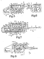
- Fig. 5 is a side elevational view with the body and cover removed, and a portion of the frame side broken out to show interior details.
- Fig. 6 is a fragmentary view of the side opposite that in Fig. 5, and showing the release slide return travel stop.
- Fig. 7 is a longitudinal section through the buckle taken at line 7-7 in Fig. 1 and viewed in the direction of the arrows.
- Fig. 8 is a view similar to Fig. 5 but showing the buckle in the latched condition.
- Fig. 9 is a cross section taken at line 9-9 in Fig. 8 and viewed in the direction of the arrows and showing the removable latching tongue in dotted lines.
- Fig. 10 is a cross section taken at line 10-10 in Fig. 7 and viewed in the direction of the arrows.
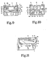
- Fig. 11 is a fragmentary view similar to Fig. 5 but including also the body and cover as in Fig. 7, and showing a preferred embodiment of the buckle release slide and top cap.
- Fig. 12 is a rear elevational view of the release button top cap.
- Fig. 13 is a side elevational view of the release button top cap.
- Fig. 14 is a bottom view of the release button top cap.
- Fig. 15 is a top plan view of the release slide without the top cap.
- Fig. 16 is a section through the release slide assembly taken at the location of line 16-16 in Fig. 15 and viewed in the direction of the arrows and showing the cap latched in place.
- Fig. 17 is a section through the release slide assembly taken at line 17-17 in Fig. 15 and viewed in the direction of the arrows and showing the cap latched in place.
- Fig. 18 is a side elevational view of an alternate embodiment of the buckle and wherein the release slide of this embodiment includes a removable top cap as is done in the embodiment of Figs. 12 through 17, rather than the removable front end cap as in the embodiments of Figs. 1 through 10, and with a portion of the body, cover and frame omitted to show side rib details of the latch member and release slide according to this embodiment.
- Fig. 19 is a cross section therethrough taken at line 19-19 in Fig. 18 and viewed in the direction of the arrows.
- Fig. 20 is a side elevational view of the latch member itself.
- Fig. 21 is a top plan view of the latch member.
- Fig. 22 is a top plan view of the release slide in the frame.
- Fig. 23 is a front elevational view of the release slide.
- Fig. 24 is a side elevational view of the release slide.
- Referring now to the drawings in detail, particularly Figs. 1-10, the exterior features of the buckle assembly include a body 11,
cover 12, andrelease button slide 13 andbutton front 14. These are all typically made of plastic and may be of a color or colors selected for desired esthetic effect. A buckle frame made of stamped steel is mounted in the body and includes abase 16, parallelupstanding sidewalls 17, a first pair of co-planar inwardly-turned and facing flanges orears 18, (Figs. 1 and 10) and a second lower or intermediate pair of co-planar inwardly turned and facing flanges orears 19. The frame has afront flange 21 turned up from the base at the front and having anupper edge 22 which defines the lower edge of an entrance for a belt tongue inserted in the direction ofarrow 23. - The frame sidewalls, which are essentially identical to each other, have
pawl pivot apertures 24 therein. Thebase 16 has several centrally located rectangular apertures (Fig. 7). One of these is thebelt connecting aperture 25. The other two are ejectorholder mounting apertures 26 receiving the front and rear latchingfeet ejector holder 27. Shallow recesses are provided in the top surface of the bottom of the buckle body to receive and provide clearance for the latching lugs at the feet of the ejector holder. - A conventional belt latching tongue can be used with this buckle and typically includes a
steel plate 29 having some non-abrasive cushion coating around the belt mounting portion, the latter having an aperture through the coating and plate to receive the belt 30 (Fig. 8) through it. Alatching aperture 31 in the tongue plate receives alatching pawl 32 when the tongue is installed in the buckle as shown in Fig. 8. Thepawl 32 is formed on the top front end of alatching plate 33. The latching plate has a pair of pivot posts 34 (Fig. 2), one at each side, and each of which is received in one of thepawl pivot apertures 24 in theframe walls 17. Because of the substantial length of these pivot posts in the direction from the frontpivoting edge 36 thereof to therear edge 37, all of which is integral with the latch plate itself 33 and directly adjacent thepawl 32, they are very strong and well able to withstand any tongue loading that can be expected to be applied to them while the buckle is in the latched condition. Thelatching plate 33 has an upturnedrear arm 38 with a cam follower surface at itsupper front edge 38A. - The latching plate, and thereby
pawl 32, is biased in a clockwise direction by a leaf spring 39 (Figs. 5 and 7) whose upper curved portion is received and directly engages the latching plate in a concavity directly under the pawl. The base of the spring rests on the base of the frame, and hasend 39A which hooks around the front edge of thefront hole 26 in the base, and is sandwiched and held in place by ejectorholder latching foot 27A. - The
pawl release slide 13 has flat, horizontally spaced, co-planar longitudinally extendingbottom surfaces frame flanges 19. The normal forward rest position for this slide when the belt tongue is unlatched is shown in Figs. 1-5 and 7 where it is urged forward by a releasereturn coil spring 41 urging the slide forward in the direction ofarrow 42. Forward movement in that direction is stopped by engagement of the front face of aboss 13C (Figs. 4 and 5) of the slide with the upperrear edge 38B of thelatch plate arm 38. The rear support for therelease return spring 41 is provided by anupstanding post 27C integral with the rear end ofejector holder 27. The spring seats in pocket 27D, centered on a pin mounted to thepost 27C at the center of the pocket. The front end of the spring is seated on wall 13D at the front of a rearward-opening spring housing cavity in theslide 13, and is centered onintegral pin 13E (Figs. 4 and 7) at the front wall. - The
ejector holder 27 has thespring seat post 27C andrear latching foot 27B at the top and bottom, respectively, of arear wall 27E. It hasfront latching foot 27A at the bottom of front wall 27F. The ejector holder is made of a durable, low-friction plastic, having some resilience so that the front and rear feet can be pressed toward each other sufficiently during assembly to enter theholes 26, and then released to snap into secure engagement with the front and rear margins of the front and rear holes, respectively, with the hook portions of the feet retaining the feet on the base. The two longitudinally extendingside walls ejector 43, which has laterally projectinglower side flanges ejector holder 27. The ejector is also made of a durable low-friction plastic and is biased forward by a coil spring 44 (Fig. 7) whose rear end is received around the projecting boss and seated on therear wall 27E of the ejector holder. Thespring 44 extends forward underspring 41 through the open space 46 (Fig. 4) betweenwalls head 43A with afront end 43B which faces the approaching belt tongue. - To aid insertion of the belt tongue into the buckle entrance, guidance is available from the inclined faces of the release button front at the top of the entrance, the cover and body front at the sides of the entrance, and the body front at the bottom of the entrance, which inclined faces cooperate to form a sort of entrance trough (as indicated in Figs. 3 and 7). Having passed the entrance guide trough, the tongue will continue to be guided by the inside faces of the
side walls 17, thebottom face 13S of the release slide, and theupper edge 22 offront flange 21. The leading edge of the tongue will engage thefront end 43B of the ejector and push it to the rear against the bias of thespring 44. As soon as the latchingaperture 31 of the tongue passes therear end 32A of the pawl, thepawl return spring 39 will force the pawl upward into latching position in theaperture 31. This condition is shown in Fig. 8. Asarm 38 of latchingmember 33 rises,edge 38B moves up and off of theboss 13C permitting the release slide to move forward slightly under the urging of thespring 41. This forward return movement of the release slide is stopped by abutment of the downwardly extendingrear flange 13R of the slide with the rear surface of thelatch plate arm 38. - To prevent inadvertent release of the pawl in response to large accelerations perpendicular to the buckle such as in the direction of the
arrow 47 in Fig. 2, a pawl lock catch is provided by theboss 13C as it projects out from the release slide between therelease cam surface 13F and the sliderear end flange 13R and, in fact, projects forwardly from the lower edge offlange 13R (Fig. 5) and laterally outward from the spring cavity wall of the slide (Figs. 9 and 10). Thelatch plate arm 38 has an inwardly projectingwing 38C (Figs.4,9 and 10) which projects inwardly over the top of the pawl lock catch when the release button is in the normal rest position with the buckle latched as shown in Figs. 8 and 9. In the event of acceleration of the buckle frame in the direction ofarrow 47 enough to overcome the latching force of thepawl return spring 39, the relative movement of the pawl opposite direction ofarrow 47 is stopped by the abutting engagement of the bottom edge ofwing 38C of thelatch plate arm 38 with top of the pawllock catch boss 13C. - In order to release the tongue, it is necessary to move the pawl down out of the
aperture 31 in the tongue. For this purpose, the downwardly and rearwardly facingrelease cam surface 13F (Figs. 3, 5 and 8) is provided on the slide and is engageable with thecam follower surface 38A as the slide is pushed to the rear in the direction of arrow 23 (Fig. 1). Pushing the slide to the rear causes the cam to drive the follower down, thus pivoting the latchingplate 33 in a counterclockwise direction about thepivot edge 36 and against the urging of thespring 39. As the pivoting occurs, the pawl moves out of theaperture 31. When this occurs, the ejector slides forward (arrow 42 in Fig. 7) as forced to do so by thespring 44, pushing the tongue out of the buckle. It is sufficiently forceful to eject the tongue completely out, even though the ejector travel is limited by the front end wall 27F of the ejector holder. As the ejector pushes the tongue out, thefront end 43B of the ejector head moves over the top of the depressed pawl as it is shown beginning to do in Fig. 7. Since theejectors lateral flanges spring 39 urging of the latching plate upward at the pawl. Instead, theejector head 43A holds the latching plate down. This condition persists until thetongue 29 is re-inserted to push the ejector back but, at that time, the tongue will maintain the latching pawl depressed untiltile latching aperture 31 has moved in far enough for the pawl to rise into latching position of Figs. 8 and 9 again. The maintenance of the pawl in the depressed unlatching position makes it easy to insert the tongue and, consequently, reduces wear on the tongue and pawl. - The downward slope of the buckle entrance front surface of the body 11, which starts downward immediately in front of the
frame front flange 21, minimizes the likelihood that a coin or other foreign object can become lodged in the buckle entrance. The upper rear end of the body front surface at the buckle entrance at front frame flange edge 22 (FIG. 7) is preferably less than .625 inches from thefront end 43B of the ejector head when the ejector is in the rest position. Nevertheless, if it somehow happens that the ejector is pushed back (other than by the entering tongue) to the point where it will uncover the pawl, the pawl may rise and inhibit subsequent insertion of the tongue. This can be overcome by manually pushing the release button to the rear in the normal way to pivot the pawl down out of the way as the tongue is inserted. - The arrangement of the components, and particularly the slope of the
cam 13F, distance of the cam follower edge from thepivot edge 36, location of thepawl edge 32A from the pivot edge, is such as to give a 4 to 1 mechanical advantage to the user pushing the end of thebutton 14 to release the buckle. Also it provides a half inch button travel from the latching rest position of Fig. 8 to a pawl release position shown dotted in Fig. 5. This is in a buckle whose overall dimensions are about 3.2 inches long, 1.2 inches high and 1.8 inches wide. This relatively significant button travel for release minimizes the chance of inadvertent release by the user. Use of the pivoting pawl and low-friction materials such as Teflon for the slide and ejector contribute to the ease of operation. The formed steel frame with the inwardly foldedlower flanges 19 and upturnedfront flange 21 support the tongue during prying loads. The inwardly foldedupper flanges 18 increase crush resistance and enhance protection of the internal components. - A further feature of the invention pertains to the button front. As shown in Figs. 3 and 5-8, the lower portion of the
button front 14 is sloped inward to provide the upper wall of the entrance "trough." In this embodiment, this button front is a cap distinct from the rest of the slide and has twoslots 14A and 14B (Fig. 7) in a rear face thereof which receive mating features 13M and 13N respectively of the slide, 13M being the front edge of the top of the slide, and 13N being a rib on the front wall of the slide. Side-locatedcatch tabs 14C project rearward from the button front, and have inwardly projecting catch shoulders 14D received in side opening cavities at the front of the slide, whereby the tabs are latched to the rear faces of thefront walls 13L of the cavities. The material of thebutton front cap 14 can be a plastic identical in color and composition to that of the body 11 andcover 12. ABS material is an example. Thetabs 14C are flexible enough to permit spreading them to install thefront cap 14 on the slide, but resilient and stiff enough to remain firmly in place, once installed. This feature enables standardization of the internal components of the buckle, including the slide, but using outer materials for the body, cover and slide front cap as specified by the customer of the buckle manufacturer. The front of thecap 14 is convex curved or crowned as shown best in Fig. 1, which facilitates finding it by feel in the dark. The separability of thecap 14 from the slide, as just described, enables not only choice of color but also a different style front. - Another feature facilitating standardization is the provision of the
apertures 17A in the side walls of the frame, and the rise withaperture 25 in the rear of the base as shown in Figs. 4 and 7. The body 11 and cover 12 are joined by ultrasonic welding or other suitable means at the line 11T (Figs. 2 and 3). In the illustrated embodiment, the body has a bottom rear opening with upwardly extending tabs 11A received in theaperture 25 of the frame base. This enables anchoring the buckle to a belt attachment fitting entering the bottom. Alternatively, if it is desired to use a fitting entering the side, a body with side openings in registry with theframe openings 17A, can be used. - A
slot 16A is provided in the base 16 to accommodate the lower end ofarm 38 of the latch plate when it is pushed down to the position of Fig. 5 by operation of the release slide. Rearward travel of the slide will be stopped by engagement of the upper rear wall of the button front with the front edge 12A of thecover 12. If it somehow happens that, after the slide returns to the unlatch rest position of Fig. 5, the latching plate is bumped downward relative to the slide, and disengages thestop boss 13C, theslide return spring 41 will force the slide forward. It would exit completely from the buckle except for astop shoulder 13G (Figs. 6 and 9) at the bottom rear of the right hand side of the slide, and which will abuttingly engage the rear end of theflange 19. That shoulder is located at the rear end of the slidebearing extension arm 13H (Figs. 4, 6 and 9). If it is desired to remove the slide from the frame while the buckle body and cover are off, this arm can be resiliently bent upward relative to the slide and theflange 19, since there is a slot 13J (Fig. 4) between this arm and the slide spring cavity wall, so the arm is cantilevered from the part of the slide directly in front of it, and is not attached at the side of the slide. When the rear end of the arm is bent upward, then theshoulder 13G will clear the rear end of theflange 19 and permit removal of the slide from the frame. Re-installation can be done by likewise bending the arm upward to clear the front edge of theflange 19. - Referring to Figs. 11-17, a preferred embodiment of release slide is shown at 53. Instead of having the closed top and bottom with open side construction as in
slide 13, theslide 53 is more open at the top and closed at the sides. This enables snap-on mounting ofcap 54 on the top of the slide immediately behind theupstanding front flange 56 which, on the first-described embodiment, was part of the snap-onfront end cap 14. To be specific, thecap 54 has twofront legs 54A and tworear legs 54B. Each of these has an outwardly directed shoulder adjacent its lower end as best shown in Fig. 12. These shoulders slide downward along thevertical web walls 53A and 53B of theslide 53 as the cap is pushed down onto the slide, until the shoulders reach the lower edges of the webs, whereupon the legs resiliently snap outward, and the shoulders move out under the lower edges of the webs. - It can be seen in Fig. 12, that the cap has a slight crown. The lower outer edges first contact the outboard
top surface 53C of the slide. As the cap is finally pushed flat into place, the leg shoulders snap out under the lower edges ofwalls 53A and 53B. When the cap installing force is released, the stress introduced in the cap as the crown was pushed flat, serves to pull upward on thelegs web walls 53A and 53B at 53D and 53E, respectively. The bottom surfaces 53F of theslide 53 are slidably received on the top of theframe flanges 19 as in the first-described embodiment. Theslide 53 thus operates in all respects as described above with reference to slide 13. The advantage of this embodiment is that the slide can be a bright color such as red or orange in all frame assemblies in production quantities. But where various decorative colors are to be used for the body and cover, the top of the slide can be covered with a cap of matching color. The only portion displaying the bright color is the end which is to be pushed to release the tongue. For example, in the buckle assembly of Fig. 11, with the body and cover 12 colored blue, thecap 54 is a matching blue, but theslide 53 and its exposed front face is a bright red, making it easy for the user to see where to push to unlatch the tongue. The same standardized frame and slide, without cap, can be adapted to any desired color scheme by selecting the desired body, cover and cap. - Referring now to Figs. 18 through 24, the buckle according to the embodiment shown in these figures is very similar to that shown in the preceding figures and described above. The overall arrangement and function of the components is essentially the same. Specific parts corresponding in substance to those in the previously described embodiment are provided with the additional digit "1" in front of the same reference numeral as was used in the preceding embodiment. However, in this particular embodiment, there are scallops shown on the side of the
latch plate 133 add which can best be seen in Figs. 18 through 21. The scallops are also continued up the outboard edge oflatch plate arm 138. These scallops have typical radii of .025 inches and a total depth of .025 inches. The high points thereof contact the interior face of theframe sidewall 117 which provides a guide surface for the latch plate as it is pushed down upon insertion of the buckle, and returned to latching position by thereturn spring 139 which is exactly the same as shown in the preceding embodiment. Also, therelease slide 113 has horizontally-spaced vertical ribs along each of its sides. These ribs are horizontally spaced (about .150 inches on center) and the high points thereof (about .025 inches high) contact the guide surfaces of the inside faces of theupstanding sidewalls 117 of the frame. The ribs are semi-cylindrical in cross sectional shape with a radius of .025 inches. The scallops and ribs provide relief between points of bearing of the guide surfaces and the slide and the latch member edge and contribute to freedom of movement in dirty environments. - While the invention has been illustrated and described in detail in the drawings and foregoing description, the same is to be considered as illustrative and not restrictive in character, it being understood that only the preferred embodiment has been shown and described and that all changes and modifications that come within the spirit of the invention are desired to be protected.
Claims (6)
a body having an entrance to admit a latchable tongue;
a latch member in said body and having a latching pawl thereon;
said latch member being pivotable in said body to enable said latching pawl to move into a latching position to interfere with movement of a tongue through said entrance;
guide means in said body defining a guideway for a release slide; and
a release slide received in said guideway and having a pawl release cam thereon, said slide having a rest position and a release position, and normally biased to said rest position;
resilient means mounted between said body and said latch member and operating independently of said release slide and urging said pawl to said latching position;
said latch member having a cam follower engageable by said cam when said slide is moved from said rest position to said release position to move said latching pawl out of said latching position; and
a spring loaded ejector behind said entrance and in the path of a latchable tongue when inserted through said entrance, and operable between a cocked position and a rest position;
said ejector being movable along a path traveled by the tongue as the tongue is moved into the body through said entrance, and returnable along said path as the tongue is removed from the body.
said ejector includes a front portion directly and abuttingly engageable with the end of said tongue as the tongue is inserted in the entrance, said ejector being resiliently biased to resist entrance of the tongue, said front portion being immediately above said latch pawl and is movable over said latch pawl when said tongue is removed, to intercept said latch pawl as the tongue is removed from the buckle to prevent said pawl from moving into said latching position during absence of the tongue from the buckle.
a return spring in said body and biasing said ejector toward said entrance to forceably eject said tongue from said entrance when said pawl is moved out of latching position.
said release slide includes unlatch blocker means located in abutting relation with a pawl lock portion of said latch member when said pawl is in said latching position and said release slide is in said rest position to prevent said pawl from moving out of said latching position in response to acceleration of said body in a direction transverse to said path.
a housing having an entrance to admit a latchable tongue, and having first guide means therein to guide the tongue along a first path in the housing;
a latch member in said housing to latch the tongue therein;
a release member slidable in said housing along a second path parallel to said first path and operable on said latch member to unlatch the tongue;
second guide means in said housing for guiding said release member;
a cap attached to said release member;
with resilient latch means attaching the cap to the release member;
said housing and cap are made of the same material composition and color, and said release member is made of a different material composition.
a body having an entrance to admit a latchable tongue;
a latch member in said body and having a latching pawl thereon;
said latch member being pivotable in said body to enable said latching pawl to move into a latching position to interfere with movement of a tongue through said entrance;
resilient means urging said pawl to said latching position;
guide means in said body defining a guideway for a release slide; and
a release slide received in said guideway and having a rest position and a release position, and normally biased to said rest position;
said release slide having ribbed surface means guidingly engaged by and slidable on a portion of said guide means for sliding movement from said rest position to said release position; and
said latch member having a portion engageable by a portion of said slide when said slide is moved from said rest position to said release position to move said latching pawl out of said latching position.
Applications Claiming Priority (2)
| Application Number | Priority Date | Filing Date | Title |
|---|---|---|---|
| US357805 | 1982-03-15 | ||
| US07/357,805 US4942649A (en) | 1988-02-25 | 1989-05-30 | Safety belt buckle |
Publications (2)
| Publication Number | Publication Date |
|---|---|
| EP0401455A1 true EP0401455A1 (en) | 1990-12-12 |
| EP0401455B1 EP0401455B1 (en) | 1994-01-19 |
Family
ID=23407101
Family Applications (1)
| Application Number | Title | Priority Date | Filing Date |
|---|---|---|---|
| EP89810813A Expired - Lifetime EP0401455B1 (en) | 1989-05-30 | 1989-10-30 | Safety belt buckle |
Country Status (4)
| Country | Link |
|---|---|
| US (1) | US4942649A (en) |
| EP (1) | EP0401455B1 (en) |
| JP (1) | JPH037103A (en) |
| DE (1) | DE68912580T2 (en) |
Cited By (11)
| Publication number | Priority date | Publication date | Assignee | Title |
|---|---|---|---|---|
| DE4206944A1 (en) * | 1991-04-03 | 1992-10-08 | Leonid Teder | Lock for road vehicle safety belt with holder - incorporates U=shaped lock component with tooth at front end engaging through aperture in insertable tongue |
| WO2007054280A1 (en) * | 2005-11-08 | 2007-05-18 | Takata-Petri Ag | Cladding shell for cladding a visible element of a vehicle safety belt device |
| USD655223S1 (en) | 2010-09-15 | 2012-03-06 | Amsafe Commercial Products, Inc. | Buckle assembly |
| USD661619S1 (en) | 2010-09-15 | 2012-06-12 | Amsafe Commercial Products, Inc. | Buckle assembly |
| US8327513B2 (en) | 2005-06-09 | 2012-12-11 | Amsafe, Inc. | Buckle assembly having single release for multiple belt connectors |
| US8393645B2 (en) | 2009-11-02 | 2013-03-12 | Amsafe Commercial Products, Inc. | Devices for adjusting tension in seat belts and other restraint system webs, and associated methods |
| US9775410B2 (en) | 2014-12-16 | 2017-10-03 | Shield Restraint Systems, Inc. | Web adjusters for use with restraint systems and associated methods of use and manufacture |
| US9814282B2 (en) | 2016-02-02 | 2017-11-14 | Shield Restraint Systems, Inc. | Harsh environment buckle assemblies and associated systems and methods |
| US10086795B2 (en) | 2015-10-02 | 2018-10-02 | Shield Restraint Systems, Inc. | Load indicators for personal restraint systems and associated systems and methods |
| US10604259B2 (en) | 2016-01-20 | 2020-03-31 | Amsafe, Inc. | Occupant restraint systems having extending restraints, and associated systems and methods |
| US10611334B2 (en) | 2017-02-07 | 2020-04-07 | Shield Restraint Systems, Inc. | Web adjuster |
Families Citing this family (21)
| Publication number | Priority date | Publication date | Assignee | Title |
|---|---|---|---|---|
| US5383257A (en) * | 1993-04-05 | 1995-01-24 | American Cord & Webbing Co., Inc. | Co-injection molded buckle |
| US5377393A (en) * | 1993-09-03 | 1995-01-03 | Trw Vehicle Safety Systems Inc. | Seat belt buckle |
| US5568676A (en) * | 1995-03-08 | 1996-10-29 | Indiana Mills And Manufacturing, Inc. | End release buckle |
| JP3455428B2 (en) * | 1998-06-17 | 2003-10-14 | 株式会社東海理化電機製作所 | Buckle switch and buckle |
| US6273505B1 (en) | 1999-10-22 | 2001-08-14 | Graco Children's Products Inc. | Web adjuster for infant products |
| US6457219B1 (en) * | 2001-07-26 | 2002-10-01 | Kim Ging Hui Enterprise Limited | Side release buckle |
| US7093331B1 (en) | 2004-03-05 | 2006-08-22 | Amsafe Commercial Products, Inc. | Buckle and frame for restraint system resistant to a harsh environment |
| US8151937B2 (en) * | 2006-05-12 | 2012-04-10 | Edward Gerald Blemel | Levitator—ergonomic worker support system |
| DE202007011066U1 (en) * | 2007-08-08 | 2007-10-18 | Key Safety Systems, Inc., Sterling Heights | belt buckle |
| US7647678B2 (en) * | 2007-09-27 | 2010-01-19 | Tk Holdings Inc. | Contamination resistant buckle |
| US8303043B2 (en) | 2008-09-29 | 2012-11-06 | Amsafe, Inc. (Phoenix Group) | Tensioning apparatuses for occupant restraint systems and associated systems and methods |
| US7904997B2 (en) | 2008-11-07 | 2011-03-15 | Amsafe, Inc. | Buckles for inflatable personal restraint systems and associated systems and methods |
| US8469401B2 (en) | 2009-02-23 | 2013-06-25 | Amsafe, Inc. | Seat harness pretensioner |
| WO2011056989A1 (en) | 2009-11-04 | 2011-05-12 | Amsafe Commercial Products, Inc. | Restraint system buckle components having tactile surfaces, and associated methods of use and manufacture |
| US8627554B1 (en) | 2010-05-03 | 2014-01-14 | Amsafe, Inc. (Phoenix Group) | Buckle assemblies with swivel and dual release features and associated methods of use and manufacture |
| US8777323B2 (en) | 2010-07-20 | 2014-07-15 | Amsafe, Inc. | Restraint harnesses and associated methods of use and manufacture |
| US9022483B2 (en) | 2012-06-07 | 2015-05-05 | Shield Restraint Systems, Inc. | Seatbelt buckle tongue assembly |
| US9277788B2 (en) | 2013-02-19 | 2016-03-08 | Amsafe, Inc. | Dual release buckle assemblies and associated systems and methods |
| EP2958453A4 (en) | 2013-02-19 | 2016-07-27 | Amsafe Inc | Buckle assemblies with lift latches and associated methods and systems |
| DE102015105805B4 (en) | 2014-04-25 | 2021-12-30 | GM Global Technology Operations LLC (n. d. Ges. d. Staates Delaware) | Seat belt buckle assembly resistant to spills |
| SE541797C2 (en) * | 2017-11-30 | 2019-12-17 | Husqvarna Ab | Tool belt |
Citations (5)
| Publication number | Priority date | Publication date | Assignee | Title |
|---|---|---|---|---|
| DE2828049A1 (en) * | 1978-06-26 | 1980-01-10 | Autoflug Gmbh | Vehicle safety belt lock - has button, tongue and housing, with sloping guide surface for sliding latch piece |
| FR2464666A1 (en) * | 1979-09-14 | 1981-03-20 | Securaiglon Sa | Buckle for vehicle safety belt - has articulated lever engaging with press button to open it |
| US4382320A (en) * | 1980-09-02 | 1983-05-10 | Fuji Kiko Kabushiki Kaisha | Seat belt buckle |
| DE3404508A1 (en) * | 1983-02-18 | 1984-08-23 | Firestone Tire & Rubber Co | FINAL RELEASE BUCKLE |
| US4678928A (en) * | 1984-12-26 | 1987-07-07 | Kabushiki Kaisha Tokai-Rika-Denki-Seisakusho | Controller for automatically effecting disengagement of buckle device |
Family Cites Families (29)
| Publication number | Priority date | Publication date | Assignee | Title |
|---|---|---|---|---|
| GB1122784A (en) * | 1965-08-20 | 1968-08-07 | Britax London Ltd | Buckles for safety belts |
| GB1126919A (en) * | 1966-08-17 | 1968-09-11 | Britax London Ltd | A safety belt buckle |
| US4127922A (en) * | 1976-02-18 | 1978-12-05 | Nsk-Warner, K.K. | Latch device for a safety belt buckle in a vehicle and method of assembling the same |
| FR2379995A2 (en) * | 1976-04-28 | 1978-09-08 | Peugeot Aciers Et Outillage | BUCKLE FOR SAFETY STRAP |
| GB1589993A (en) * | 1976-06-30 | 1981-05-28 | Nsk Warner Kk | Seat belt buckle |
| US4128924A (en) * | 1977-02-17 | 1978-12-12 | Indiana Mills & Manufacturing Inc. | Laminated seat belt buckle |
| US4121327A (en) * | 1977-08-01 | 1978-10-24 | Irvin Industries Inc. | Clip ejector for safety seat belt buckle |
| GB1589059A (en) * | 1978-05-12 | 1981-05-07 | Securon Ag | Buckle for safety belts and seat belts |
| US4197619A (en) * | 1978-09-22 | 1980-04-15 | Britax (Wingard) Limited | Tongue and buckle fastener for a safety belt harness |
| DE2929803C2 (en) * | 1979-07-23 | 1984-12-06 | Repa Feinstanzwerk Gmbh, 7071 Alfdorf | Belt buckle for a seat belt |
| FR2482429A2 (en) * | 1980-05-14 | 1981-11-20 | Peugeot Aciers Et Outillage | LOOP FOR SAFETY STRAP |
| FR2482430B1 (en) * | 1980-05-14 | 1983-12-23 | Peugeot Aciers Et Outillage | |
| JPS621929Y2 (en) * | 1980-06-30 | 1987-01-17 | ||
| EP0052160B1 (en) * | 1980-11-18 | 1984-07-25 | Autoflug Gmbh | Buckle for a safety belt |
| US4358879A (en) * | 1980-12-01 | 1982-11-16 | General Motors Corporation | Seat belt buckle |
| DE3047664A1 (en) * | 1980-12-18 | 1982-07-22 | Autoflug Gmbh, 2084 Rellingen | CENTRAL BELT LOCK, ESPECIALLY FOR PLANE BELTS |
| US4368563A (en) * | 1981-07-13 | 1983-01-18 | Allied Corporation | Seat belt buckle with plastic cover |
| US4425688A (en) * | 1981-11-06 | 1984-01-17 | Indiana Mills & Manufacturing, Inc. | Child belt buckle |
| DE3200770A1 (en) * | 1982-01-13 | 1983-07-21 | Autoflug Stakupress GmbH & Co, 2000 Norderstedt | BUCKLE FOR A BELT |
| US4535514A (en) * | 1982-09-27 | 1985-08-20 | Gateway Industries, Inc. | Seat belt with plastic cover |
| JPS5983409U (en) * | 1982-11-30 | 1984-06-05 | 日本精工株式会社 | Buckle for seat belt |
| DE3422692C3 (en) * | 1983-06-21 | 1994-07-28 | Autoflug Gmbh | Seat belt lock |
| US4562625A (en) * | 1983-12-21 | 1986-01-07 | Gateway Industries, Inc. | Seat belt buckle |
| US4611369A (en) * | 1985-02-25 | 1986-09-16 | Trw Repa Gmbh | Belt lock for a safety belt |
| US4614010A (en) * | 1985-06-03 | 1986-09-30 | Trw Inc. | Safety belt buckle |
| FR2582916B1 (en) * | 1985-06-10 | 1987-09-18 | Peugeot Aciers Outillages | BUCKLE, ESPECIALLY A SEAT BELT. |
| FR2584901B1 (en) * | 1985-07-17 | 1987-11-27 | Peugeot Aciers Et Outillage | IMPROVED BUCKLE, ESPECIALLY FOR A SEAT BELT |
| US4692970A (en) * | 1985-08-05 | 1987-09-15 | Indiana Mills & Manufacturing, Inc. | Belt buckle with eject means |
| US4617705A (en) * | 1985-08-05 | 1986-10-21 | Indiana Mills & Manufacturing, Inc. | Child belt buckle |
-
1989
- 1989-05-30 US US07/357,805 patent/US4942649A/en not_active Expired - Lifetime
- 1989-10-30 EP EP89810813A patent/EP0401455B1/en not_active Expired - Lifetime
- 1989-10-30 DE DE68912580T patent/DE68912580T2/en not_active Expired - Fee Related
- 1989-10-30 JP JP1282848A patent/JPH037103A/en active Pending
Patent Citations (5)
| Publication number | Priority date | Publication date | Assignee | Title |
|---|---|---|---|---|
| DE2828049A1 (en) * | 1978-06-26 | 1980-01-10 | Autoflug Gmbh | Vehicle safety belt lock - has button, tongue and housing, with sloping guide surface for sliding latch piece |
| FR2464666A1 (en) * | 1979-09-14 | 1981-03-20 | Securaiglon Sa | Buckle for vehicle safety belt - has articulated lever engaging with press button to open it |
| US4382320A (en) * | 1980-09-02 | 1983-05-10 | Fuji Kiko Kabushiki Kaisha | Seat belt buckle |
| DE3404508A1 (en) * | 1983-02-18 | 1984-08-23 | Firestone Tire & Rubber Co | FINAL RELEASE BUCKLE |
| US4678928A (en) * | 1984-12-26 | 1987-07-07 | Kabushiki Kaisha Tokai-Rika-Denki-Seisakusho | Controller for automatically effecting disengagement of buckle device |
Cited By (11)
| Publication number | Priority date | Publication date | Assignee | Title |
|---|---|---|---|---|
| DE4206944A1 (en) * | 1991-04-03 | 1992-10-08 | Leonid Teder | Lock for road vehicle safety belt with holder - incorporates U=shaped lock component with tooth at front end engaging through aperture in insertable tongue |
| US8327513B2 (en) | 2005-06-09 | 2012-12-11 | Amsafe, Inc. | Buckle assembly having single release for multiple belt connectors |
| WO2007054280A1 (en) * | 2005-11-08 | 2007-05-18 | Takata-Petri Ag | Cladding shell for cladding a visible element of a vehicle safety belt device |
| US8393645B2 (en) | 2009-11-02 | 2013-03-12 | Amsafe Commercial Products, Inc. | Devices for adjusting tension in seat belts and other restraint system webs, and associated methods |
| USD655223S1 (en) | 2010-09-15 | 2012-03-06 | Amsafe Commercial Products, Inc. | Buckle assembly |
| USD661619S1 (en) | 2010-09-15 | 2012-06-12 | Amsafe Commercial Products, Inc. | Buckle assembly |
| US9775410B2 (en) | 2014-12-16 | 2017-10-03 | Shield Restraint Systems, Inc. | Web adjusters for use with restraint systems and associated methods of use and manufacture |
| US10086795B2 (en) | 2015-10-02 | 2018-10-02 | Shield Restraint Systems, Inc. | Load indicators for personal restraint systems and associated systems and methods |
| US10604259B2 (en) | 2016-01-20 | 2020-03-31 | Amsafe, Inc. | Occupant restraint systems having extending restraints, and associated systems and methods |
| US9814282B2 (en) | 2016-02-02 | 2017-11-14 | Shield Restraint Systems, Inc. | Harsh environment buckle assemblies and associated systems and methods |
| US10611334B2 (en) | 2017-02-07 | 2020-04-07 | Shield Restraint Systems, Inc. | Web adjuster |
Also Published As
| Publication number | Publication date |
|---|---|
| DE68912580D1 (en) | 1994-03-03 |
| DE68912580T2 (en) | 1994-06-16 |
| EP0401455B1 (en) | 1994-01-19 |
| US4942649A (en) | 1990-07-24 |
| JPH037103A (en) | 1991-01-14 |
Similar Documents
| Publication | Publication Date | Title |
|---|---|---|
| EP0401455B1 (en) | Safety belt buckle | |
| US4876772A (en) | Safety belt buckle | |
| EP0608564B1 (en) | Belt buckle with interactive dual tongues | |
| US7520036B1 (en) | Multi-point buckle for restraint system | |
| KR100275417B1 (en) | Slide fastener slider | |
| US5813097A (en) | Dual tongue buckle with independent latching | |
| US4358879A (en) | Seat belt buckle | |
| US6606770B1 (en) | Safety buckle for child seats and the like | |
| US5979026A (en) | Buckle dual release | |
| EP0587345A1 (en) | Buckle assembly | |
| US4197619A (en) | Tongue and buckle fastener for a safety belt harness | |
| US4542563A (en) | End release buckle | |
| US4027362A (en) | Buckles for vehicle safety belts | |
| US20190133260A1 (en) | Debris resistant seatbelt buckle device | |
| US5584108A (en) | Buckle for seat belt device | |
| EP0204803A1 (en) | Buckle | |
| US4358878A (en) | Plug-in fastener for motor vehicle safety belts | |
| JPS61284202A (en) | Safety belt and buckle | |
| US3494007A (en) | Safety belt buckle | |
| US7093331B1 (en) | Buckle and frame for restraint system resistant to a harsh environment | |
| JP3455428B2 (en) | Buckle switch and buckle | |
| US4374449A (en) | Mini seat belt buckle | |
| GB2073810A (en) | Improvements in or relating to a buckle | |
| US6385823B1 (en) | Buckle with noise prevention mechanism | |
| US3533141A (en) | Pushbutton safety belt buckle |
Legal Events
| Date | Code | Title | Description |
|---|---|---|---|
| PUAI | Public reference made under article 153(3) epc to a published international application that has entered the european phase |
Free format text: ORIGINAL CODE: 0009012 |
|
| AK | Designated contracting states |
Kind code of ref document: A1 Designated state(s): DE FR GB IT |
|
| 17P | Request for examination filed |
Effective date: 19901213 |
|
| 17Q | First examination report despatched |
Effective date: 19920630 |
|
| GRAA | (expected) grant |
Free format text: ORIGINAL CODE: 0009210 |
|
| AK | Designated contracting states |
Kind code of ref document: B1 Designated state(s): DE FR GB IT |
|
| REF | Corresponds to: |
Ref document number: 68912580 Country of ref document: DE Date of ref document: 19940303 |
|
| ET | Fr: translation filed | ||
| ITF | It: translation for a ep patent filed |
Owner name: SPADINI MARUSCO |
|
| PLBE | No opposition filed within time limit |
Free format text: ORIGINAL CODE: 0009261 |
|
| STAA | Information on the status of an ep patent application or granted ep patent |
Free format text: STATUS: NO OPPOSITION FILED WITHIN TIME LIMIT |
|
| 26N | No opposition filed | ||
| PGFP | Annual fee paid to national office [announced via postgrant information from national office to epo] |
Ref country code: FR Payment date: 20011010 Year of fee payment: 13 |
|
| PGFP | Annual fee paid to national office [announced via postgrant information from national office to epo] |
Ref country code: GB Payment date: 20011031 Year of fee payment: 13 |
|
| PGFP | Annual fee paid to national office [announced via postgrant information from national office to epo] |
Ref country code: DE Payment date: 20011112 Year of fee payment: 13 |
|
| REG | Reference to a national code |
Ref country code: GB Ref legal event code: IF02 |
|
| PG25 | Lapsed in a contracting state [announced via postgrant information from national office to epo] |
Ref country code: GB Free format text: LAPSE BECAUSE OF NON-PAYMENT OF DUE FEES Effective date: 20021030 |
|
| PG25 | Lapsed in a contracting state [announced via postgrant information from national office to epo] |
Ref country code: DE Free format text: LAPSE BECAUSE OF NON-PAYMENT OF DUE FEES Effective date: 20030501 |
|
| GBPC | Gb: european patent ceased through non-payment of renewal fee | ||
| PG25 | Lapsed in a contracting state [announced via postgrant information from national office to epo] |
Ref country code: FR Free format text: LAPSE BECAUSE OF NON-PAYMENT OF DUE FEES Effective date: 20030630 |
|
| REG | Reference to a national code |
Ref country code: FR Ref legal event code: ST |
|
| PG25 | Lapsed in a contracting state [announced via postgrant information from national office to epo] |
Ref country code: IT Free format text: LAPSE BECAUSE OF NON-PAYMENT OF DUE FEES;WARNING: LAPSES OF ITALIAN PATENTS WITH EFFECTIVE DATE BEFORE 2007 MAY HAVE OCCURRED AT ANY TIME BEFORE 2007. THE CORRECT EFFECTIVE DATE MAY BE DIFFERENT FROM THE ONE RECORDED. Effective date: 20051030 |