EP0402505A1 - Continuous cyclic peritoneal dialysis system - Google Patents
Continuous cyclic peritoneal dialysis system Download PDFInfo
- Publication number
- EP0402505A1 EP0402505A1 EP89110861A EP89110861A EP0402505A1 EP 0402505 A1 EP0402505 A1 EP 0402505A1 EP 89110861 A EP89110861 A EP 89110861A EP 89110861 A EP89110861 A EP 89110861A EP 0402505 A1 EP0402505 A1 EP 0402505A1
- Authority
- EP
- European Patent Office
- Prior art keywords
- fluid
- cavity
- fill
- drain
- volume
- Prior art date
- Legal status (The legal status is an assumption and is not a legal conclusion. Google has not performed a legal analysis and makes no representation as to the accuracy of the status listed.)
- Granted
Links
Images

Classifications
-
- A—HUMAN NECESSITIES
- A61—MEDICAL OR VETERINARY SCIENCE; HYGIENE
- A61M—DEVICES FOR INTRODUCING MEDIA INTO, OR ONTO, THE BODY; DEVICES FOR TRANSDUCING BODY MEDIA OR FOR TAKING MEDIA FROM THE BODY; DEVICES FOR PRODUCING OR ENDING SLEEP OR STUPOR
- A61M1/00—Suction or pumping devices for medical purposes; Devices for carrying-off, for treatment of, or for carrying-over, body-liquids; Drainage systems
- A61M1/14—Dialysis systems; Artificial kidneys; Blood oxygenators ; Reciprocating systems for treatment of body fluids, e.g. single needle systems for hemofiltration or pheresis
- A61M1/28—Peritoneal dialysis ; Other peritoneal treatment, e.g. oxygenation
- A61M1/287—Dialysates therefor
-
- A—HUMAN NECESSITIES
- A61—MEDICAL OR VETERINARY SCIENCE; HYGIENE
- A61M—DEVICES FOR INTRODUCING MEDIA INTO, OR ONTO, THE BODY; DEVICES FOR TRANSDUCING BODY MEDIA OR FOR TAKING MEDIA FROM THE BODY; DEVICES FOR PRODUCING OR ENDING SLEEP OR STUPOR
- A61M1/00—Suction or pumping devices for medical purposes; Devices for carrying-off, for treatment of, or for carrying-over, body-liquids; Drainage systems
- A61M1/14—Dialysis systems; Artificial kidneys; Blood oxygenators ; Reciprocating systems for treatment of body fluids, e.g. single needle systems for hemofiltration or pheresis
- A61M1/16—Dialysis systems; Artificial kidneys; Blood oxygenators ; Reciprocating systems for treatment of body fluids, e.g. single needle systems for hemofiltration or pheresis with membranes
- A61M1/1601—Control or regulation
- A61M1/1603—Regulation parameters
- A61M1/1611—Weight of the patient
-
- A—HUMAN NECESSITIES
- A61—MEDICAL OR VETERINARY SCIENCE; HYGIENE
- A61M—DEVICES FOR INTRODUCING MEDIA INTO, OR ONTO, THE BODY; DEVICES FOR TRANSDUCING BODY MEDIA OR FOR TAKING MEDIA FROM THE BODY; DEVICES FOR PRODUCING OR ENDING SLEEP OR STUPOR
- A61M1/00—Suction or pumping devices for medical purposes; Devices for carrying-off, for treatment of, or for carrying-over, body-liquids; Drainage systems
- A61M1/14—Dialysis systems; Artificial kidneys; Blood oxygenators ; Reciprocating systems for treatment of body fluids, e.g. single needle systems for hemofiltration or pheresis
- A61M1/28—Peritoneal dialysis ; Other peritoneal treatment, e.g. oxygenation
- A61M1/281—Instillation other than by gravity
-
- A—HUMAN NECESSITIES
- A61—MEDICAL OR VETERINARY SCIENCE; HYGIENE
- A61M—DEVICES FOR INTRODUCING MEDIA INTO, OR ONTO, THE BODY; DEVICES FOR TRANSDUCING BODY MEDIA OR FOR TAKING MEDIA FROM THE BODY; DEVICES FOR PRODUCING OR ENDING SLEEP OR STUPOR
- A61M1/00—Suction or pumping devices for medical purposes; Devices for carrying-off, for treatment of, or for carrying-over, body-liquids; Drainage systems
- A61M1/14—Dialysis systems; Artificial kidneys; Blood oxygenators ; Reciprocating systems for treatment of body fluids, e.g. single needle systems for hemofiltration or pheresis
- A61M1/28—Peritoneal dialysis ; Other peritoneal treatment, e.g. oxygenation
- A61M1/282—Operational modes
-
- A—HUMAN NECESSITIES
- A61—MEDICAL OR VETERINARY SCIENCE; HYGIENE
- A61M—DEVICES FOR INTRODUCING MEDIA INTO, OR ONTO, THE BODY; DEVICES FOR TRANSDUCING BODY MEDIA OR FOR TAKING MEDIA FROM THE BODY; DEVICES FOR PRODUCING OR ENDING SLEEP OR STUPOR
- A61M2205/00—General characteristics of the apparatus
- A61M2205/33—Controlling, regulating or measuring
- A61M2205/3331—Pressure; Flow
- A61M2205/3344—Measuring or controlling pressure at the body treatment site
-
- A—HUMAN NECESSITIES
- A61—MEDICAL OR VETERINARY SCIENCE; HYGIENE
- A61M—DEVICES FOR INTRODUCING MEDIA INTO, OR ONTO, THE BODY; DEVICES FOR TRANSDUCING BODY MEDIA OR FOR TAKING MEDIA FROM THE BODY; DEVICES FOR PRODUCING OR ENDING SLEEP OR STUPOR
- A61M2205/00—General characteristics of the apparatus
- A61M2205/33—Controlling, regulating or measuring
- A61M2205/3331—Pressure; Flow
- A61M2205/3348—Pressure measurement using a water column
Definitions
- the invention relates to a dialysis process for purifying the blood by continuous flow of a dialysate and exchange across the peritoneal membrane.
- Hemodialysis involves the circulation of blood through a dialysis machine in which an exchange of toxic metabolites takes place across an artificial membrane outside the patient's body. This process requires the assistance of trained personnel and subjects the patient to dangers of mechanical malfunction due to the fact that blood vessels are involved.
- Peritoneal dialysis involves the infusion of a sterile dialysate into the peritoneal cavity and after absorbing waste metabolites, the dialysate is discarded. The process is then repeated until the level of metabolites is reduced to a desired level.
- This method is commonly referred to as the "Batch" method due to the fact that multiple one or two liter bottles or bags of fresh dialysate solution are utilized which require multiple connections to be made to the catheter inserted in the peritoneal cavity during the dialysis process. The multiple connections made during the course of the dialysis has been thought to be a major cause of the high instance of peritonitis.
- Continuous ambulatory peritoneal dialysis offers continuous peritoneal dialysis while still allowing the patient some off time.
- the continuous ambulatory peritoneal dialysis must be done in absence of a machine and multiple bottles or bags of dialysis must be infused daily.
- multiple infusions per day requires that multiple connections of bags or bottles to the peritoneal catheter be made.
- the production of bulk sterile dialysis for the peritoneal process has not been known to be practical for large scale application particularly for home dialysis.
- United States Patent No. 4,311,587 seeks to avoid some of the above problems with peritoneal dialysis by providing a sub-micron filter on line with the fresh dialysate to prevent peritoneal contamination.
- the system is perambulatory and the bag of dialysate is worn by the patient.
- the bag may be pressurized by numerous methods and is connected only to the inflow side of the filter.
- the outflow port of the filter is connected on the other side of the filter so that no peritoneal contaminating source is connected directly to the peritoneal cavity.
- the system is still basically a batch type system in that multiple bottles or bags of dialysate must be connected to the filter even though direct connection to the peritoneal catheter is not required.
- United States Patent No. 4,338,190 discloses a system and process which attempts to avoid the batch process method utilized heretofore in peritoneal dialysis wherein a closed loop peritoneal circuit is provided having a selective membrane across which toxic metabolites are exchanged. A solution is passed on the other side of the selective membrane for maintaining the original concentration of sugar and salt in the peritoneal fluid as the toxic metabolites pass the separator membrane. A concentrate of sugar and salts is mixed at a desired ratio with water making up the dialysis fluid. The conductivity of the fluid may be automatically monitored to adjust the concentration of the fluid during its recirculation. A double peritoneal catheter provides for the inflow and outflow of the peritoneal fluid.
- the peritoneal fluid is constantly recirculated through the peritoneal cavity and the efficiency becomes reduced slightly because of residual toxins which are put back into the peritoneal cavity.
- the selective membrane is an expensive disposable item which means that the cost of operating the system is high unless the membrane is recleaned.
- Pumping the peritoneal fluid through the peritoneal cavity is required making it difficult to assure that the patient stays properly distended during the dialysis process. If the peritoneal membrane is not fully distended, it becomes convoluted around the intestines and pockets are formed where the peritoneal fluid can hide. Incomplete circulation then results with decreased efficiency of dialysis. No control is had over the level of peritoneal fluid in the peritoneal circuit. There is no way of replenishing the peritoneal fluid should the circuit run low on fluid or run dry.
- Patent No. 3, 545,438 discloses a batch type peritoneal dialysis method which provides for partially reusing a portion of the dialysis fluid.
- the spent fluid becomes mixed with fresh dialysate.
- United States Patent No. 3,707,967 corresponding to German Patent No. 2,149,040, apparently discloses a closed loop dialysis system wherein the dialysis fluid is continuously circulated through the peritoneal membrane. The combination of flow control and monitoring in inflow and outflow lines, and a continuous, cyclic open circuit is not present in the German application.
- 3,709,222 discloses a peritoneal dialysis method generally of the batch type.
- the amount of dialysis fluid entering the peritoneal cavity and the pressure of the peritoneal cavity are controlled by varying the height of a pressure relief chamber. This can be both inaccurate and unreliable, and requires that an attendant be present in order to carry out the process.
- the cycles involved in the process are rather complicated involving an initial priming cycle which involves the filling of a proportioned chamber, the pressure relief chamber and a return chamber. To begin the process, dialysis fluid is allowed to enter the peritoneal cavity from the pressure relief chamber until the chamber is moved to a lower position which prevents the fluid from flowing.
- an automatic cycling begins in which the fluid is pumped out of the cavity into the return chamber.
- an inflow cycle begins in which the fluid is pumped from the return chamber to the proportional chamber which forces fresh dialysis from the proportioning chamber into the pressure relief chamber from where it flows into the patient.
- an equilibrium cycle in which dialysis fluid is drained from the proportioning chamber and fresh dialysis fluid is added. Apparently, during this time, dialysis fluid remains in the cavity. The process then switches back to the outflow cycle in which fluid is pumped from the cavity to the return chamber.
- French Patent No. 2,371,931 discloses a peritoneal process having a single line used for inflow and outflow. The method includes pumping in a certain amount of dialysate, letting it diffuse for a prescribed dwell time, and removing the dialysate. This is, in essence, an automatic "batch" system.
- peritoneal dialysis processes are disclosed involving continuous inflows and outflows of fluid using a double catheter in an open loop circuit in which fluid is discarded rather than recirculated.
- Other aspects of these processes involve using a single catheter open circuit system in which alternating inflow and outflow cycles occur with zero dwell time for the fluid in the cavity.
- the present invention relates to improvements in the control of these processes and to the control of the osmolality of the fluid in response to the amount of the fluid removed from the patient. The osmolality is continuously adjusted to ensure the basis of the patient.
- an important object of the present invention is to provide a continuous cycle peritoneal dialysis system and method which avoid the inherent problems and dangers of a batch type peritoneal dialysis system.
- Still another important object of the present invention is to provide a peritoneal dialysis system having a high rate of dialysate exchange providing increased dialysis efficiency.
- Still another important object of the present invention is to provide a peritoneal dialysis system and method having a high rate of dialysate exchange and dialysis efficiency in which the osmolality of the fluid is continuously adjusted in response to the amount of fluid removed from the patient.
- Still anther important object of the present invention is to provide a continuous-flow single-pass peritoneal dialysis system and method in which the pressure and volume of dialysate in the patient's peritoneal membrane may be monitored and set by the patient in a simple and convenient manner without the need of a medical attendant.
- peritoneal dialysis in which a continuous flow of sterile dialysis fluid is produced and caused to flow through the peritoneal cavity of the patient in a single-pass open-circuit.
- the exchange of toxic metabolites occurs across the patient's peritoneal membrane and the residual dialysis solution is drained away after leaving the patient's cavity.
- Positive displacement fill and drain pumps pump and meter the fluid during the fill and drain cycles.
- a manometer is connected in the flow line to monitor peritoneal pressure as a function of volume.
- a high level detector detects a high fluid level in the manometer tube to cut off the fill pump and cycle while starting the drain pump and cycle instantaneously with zero dialysis fluid dwell.
- a low level detector senses a low fluid level in the manometer tube to instantaneously reverse the drain cycle to a fill cycle.
- the revolutions of the pumps are counted during the fill and drain cycles to determine the volume of fluid put in and taken out of the cavity.
- the weight and amount of fluid removed or taken in by the patient is calculated.
- the glucose concentrate and osmolality of the solution is then varied to provide a desired osmolality and patient weight loss or addition.
- FIG. 1 a continuous inflow/outflow peritoneal dialysis process and system is illustrated in Figure 1 which includes a water purification and tempering unit 10 connected to a water source 12.
- Unit 10 may be any suitable unit for sterilizing and tempering the water, such as a conventional reverse osmosis unit.
- Unit 10 communicates through ready and enable lines 10a, 10b as shown going up to a process controller, designated generally as A.
- a dialysate proportioning unit 14 receives concentrate dialysate from a source 16 and mixes it with sterilized water from unit 10 to provide a concentrated solution of prescribed proportions of dialysate and water.
- Unit 14 may be a conventional proportioning pump having a geometry that creates a specific ratio of one fluid to another. One fluid drives the pump, the other is pumped by the pump. The fluids come out at a specific fixed ratio. Unit 14 may also include pressure regulation, temperature sensing, conductivity sensing and by-pass and drain valving. This would allow for the system to function in its three modes of operation. The first mode is the sterilize mode which is the static mode of the machine. It is full of some sterilizing solution, perhaps Clorox. The second mode of operation for the machine would be the rinsing and preparation for dialysis mode. The unit is operated in the second mode until conditions are stable and suitable for patient dialysis. The third mode would be the running mode where actual dialysis process is performed. Unit 14 is controlled by dialysis process controller A which is responding to the sensing that is taking place in unit 14 providing data to the process controller. Process controller A may be any suitable process controller of conventional design well within the capacity of one having average skill in the automatic control art.
- the system is started by actuation of a start button 18.
- the dialysis process controller may begin.
- a run light 20 on controller A will signal the patient that the machine is ready to operate and may include an additional audio, visual, or both signal to the patient.
- the patient will connect a tube set 22 from the dialysis processing unit to a single flow catheter 26 disposed in the patient's peritoneal cavity 28 in a conventional manner.
- a fill button 30 on the dialysis process controller acknowledging that he has done all of the preparation required and is ready to begin the dialysis procedure.
- a time clock 32 on controller A begins to accumulate time as the cycle is now in process.
- the time clock displays elapsed time at 32a accumulated throughout the entire cycle whether it is terminated by an alarm or by the patient or by a parameter set as a maximum number of cycles. As long as the machine is operating, then elapsed time 32 is accumulating.
- the process has now begun and the patient is receiving dialysis fluid from a fill pump B.
- Pump B preferably of the peristaltic, roller type, pumps fluid from dialysis proportioning unit 14 through line 34 to tube 22 and cavity 28. Pump B is controlled by processor A.
- pump B is connected by electrical leads 36a, 36b to controller A for delivering speed and volume signals respectively.
- the patient continues to receive fluid until a comfort level is reached.
- the patient will manually set a comfort level by pushing a fill-set button 38 when his initial fill has reached a point which he considers to be a comfortable level and feels his cavity slightly distended. Pressing button 38 will indicate to process controller A that is the fill level or volume he wishes to set and to repeat the dialysis process cycles at that particular volume of fluid.
- the process controller immediately reverses the cycle from fill to drain without any dwell time for the fluid in cavity 28. All the time the machine was filling under fill volume, the amount of fluid pumped into the patient will be metered by counter 40, and accumulated and displayed at display 40a on controller A.
- the fill volume 40a is an accumulated total as it pertains to one dialysis process for one patient. This corresponds to elapsed time 32a.
- the fill cycle stops and the drain cycle instantaneously begins at the point at which the patient pushes fill-set button 38.
- the patient presses the fill set button 38 he also sets a slidable high pressure detector 50 on a manometer means D to correspond to this fill volume.
- a fluid column tube 48 is connected to junction 42 to receive fluid and is oriented vertically in the fashion of a standpipe.
- a millipore filter 54 vents tube 48 to atmosphere.
- Column tube 48 includes high fluid and pressure detector 50 and a low level and pressure detector 52 which provide a manometer means D.
- Detectors 50,52 may be standard photocell detectors, or infrared sensors for detecting the presence or absence of fluid at the high and low levels.
- the detectors may be mounted on slide brackets 50a, 52a, so that the high/low points may be set to particular points.
- the patient calibrates the high pressure point by sliding detector 50 to the level of fluid seen when the fill set button is pushed.
- tube 48 may be slidably mounted. The high and low pressure levels will tend to remain constant for a given patient.
- Tube 48 is preferably plastic tubing and does not have to be hanging perfectly vertical. This provides a very simple yet sensitive and accurate means of sensing the pressure in the cavity and hence peritoneal volume. As little as 15 centimeters of water, a very slight pressure, may be sensed. After the patient pushes the fill set button and calibrates the high pressure detector 50, operation is automatic.
- controller A After the fill cycle, controller A, without any dwell, turns on drain pump C, preferably of the peristaltic pump type.
- the pump begins to drain fluid from cavity 28. Drain pump C is connected via junction 42 to tube 22. Pump C is controlled by controller A and there are leads 44a, 44b connected to the pump. Lead 44a delivers a speed signal to pump C and lead 44b delivers a sensed volume (rpm) signal to controller A.
- the drain cycle is a function of the fill-pump stopping and the drain pump starting.
- Fill pump B and drain pump C are positive displacement type pumps which have the ability to both pump and meter fluids.
- the accumulated fill volume is a function of the pumps pumping in and the drain is a function of pumps pumping out in rpm's.
- Cycle run display 62a of cycle counter 62 will increment to 1 showing that the first cycle is completed and another cycle has begun. That cycle will continue until the height of the fluid in the column approaches high pressure sensor 50 and the fluid does not just reach that, it pauses above that and below that.
- the pumping of pump C is not continuous, it is intermittent pumping action.
- the pump speed governs the height of the column. As the cavity 28 reaches its fill level, fluid in tube 48 will oscillate rapidly above and below high pressure detector 50 and controller A will slow pump B down. The pump speed has diminished to the point of diminishing returns, the delivery of fluid to the patient is getting ever more slow. When fluid level is generally constant in blocking detector 50, pump B will cut off.
- the cycle is reversed once again, and a drain cycle is instigated by controller A.
- the same variable speed operation of pump C occurs during the drain cycle.
- the reversing cycles continues until the patient terminates it, the maximum time has run out, fill volume has timed out, or until an alarm in the system stops it.
- the pump is pumping dialysis fluid in with the column height pressure level in every instance.
- the pump is pumping out with the low pressure maintained at low pressure sensor 52 in every instance. It is the pump speed which corresponds to a maintained column height that determines when the cycle trips.
- the pump When fill set button 38 is pressed the pump has reached a certain recorded speed. It is filling up column tube 48.
- the column height is there and the pump, for example, is at approximately 10 r.p.m.
- the pump starts out running at full r.p.m. which is about 40 r.p.m.
- the pump continues at full rate until the column reaches high pressure sensor 50. As soon as the liquid hits this level, it is going above it. It has reached this point through acceleration and is going to continue to go above that point unless the speed of the pump is decreased.
- the pump has to slow down to maintain the column height.
- the patient may press the fill-set button as frequently as he wishes throughout the entire process. For instance at the start one would probably not be as relaxed and the tissue in the abdomen would not have elasticized and perhaps would have a smaller pool areal. After his body becomes accustomed to the process, he may be able to accept more. Therefore, the patient presses the fill button and the system starts the fill until the patient presses the fill-set button. This would then give the patient a different fill volume level.
- the pressing of the fill-set button creates a memory of the exact conditions of the unit at the time the button is pressed.
- Fill is a command to fill that will continue until the fill-set button is pressed or until the system reaches an internally programmed maximum values. These values would include physiology safe values. These values, while not always comfortable to the patient, are physically undamaging. In the event of an emergency, the patient may hit a drain button 66 and then he may release the connector hoses and be released. The value where the machine automatically goes into the drain mode will presumably be something above the comfort level, but not above a safety level. This may be preset in the controller. This is not accessible by the patient.
- Means for regulating the osmolality of the dialysis solution delivered to the patient in response to the amount of the fluid removed from the patient is provided.
- the regulating means continuously adjusts the osmolality of the solution to ensure that a desired amount of fluid is removed, or in some cases, added.
- the regulating means includes a glucose pump E, preferably of the peristaltic type, connected to the inflow line upstream of fill pump B and the inlet of pump E is connected to a source of glucose 70. Pump E is controlled by controller A in response to the amount of fluid removed from a patient to adjust the glucose concentrate and osmolality of the dialysate coming from source 16 in order to achieve a desired patient weight loss.
- fill pump B and drain pump C are fixed volume roller pumps which quite accurately serve to meter the amounts of fill and drain fluids. By measuring the number of revolutions per minute of the pump and pumping time, the volume of fill and drain fluid may be accurately metered and determined.
- glucose pump E in regards to the amount of glucose pumped and mixed with the dialysis fluid in order to accurately determine the glucose concentrate and osmolality of the solution.
- the dry weight of that patient can easily be estimated.
- the amount of weight loss desired during dialysis can be determined. This determines the amount of fluid removed from the patient during dialysis. Based on the length of time the process is to run, the amount and ratio of glucose needed for the desired weight loss can be determined.
- Controller A calculates the volume of fill and drain fluid from the volumetric r.p.m. signals on leads 36b and 44b from the respective pumps. By comparing these signals, it can be determined how much fluid is being removed from the patient. If the weight, i.e. fluid, is not being adequately removed, a drive signal is sent to glucose pump E from controller A via lead 72 to speed up the pump, increase the glucose supplied to the dialysis fluid, and increase fluid removal. If too much weight is being removed, the glucose pump is slowed down to reduce the amount and ratio of glucose mixed with the fluid. Adjusting the glucose concentrate and osmolality automatically allows for a standard dialysate solution to be supplied at 16. The concentrate can easily be tailored to the patient by varying the glucose amount via pump E.
- the concentrate may easily be varied in an automatic convenient manner in accordance with the process and system of the invention.
- the glucose is automatically varied during the dialysis process to achieve a desired weight loss, or addition if the case may be.
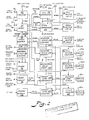
- FIG. 1 a block diagram of one suitable controller is illustrated.
- a start/stop circuit 80 driven by manual push buttons allows starting, stopping, and continuing of the process without losing the control parameters or data accumulated thus far in the event the patient must adjust for position, comfort or temporary interruptions.
- a run indicator 80a glows when process is proceeding.
- a mode 82 circuit determines the fill/drain cycle of operations. Fill and drain manual push buttons 30, 66 may be activated at any time to interrupt the automatic control and force a change to the opposite mode.
- a fill comparator 84 is connected to a motor drive 86 of pump B and monitors the fill mode and limits the fill speed of pump B to the setting on the maximum fill rate and causes the mode circuit to reverse when the peritoneal pressure during any cycle reaches the predetermined maximum value on the pressure set control.
- a drain comparator 88 is connected to motor drive 90 of drain motor C and monitors the drain mode to limit the drain speed of pump C to the setting on the maximum drain rate and causes the mode circuit to reverse when the peritoneal pressure during any drain cycle reaches the predetermined minimum value on the preset pressure control.
- Fill set button 38 is used by the patient during the first fill half-cycle of a treatment to establish the maximum fill volume and store in memory. Patient comfort is the criteria for this setting.
- Fill/drain indicators 30a, 66a show which mode the system is in at the moment.
- a fill/drain motor drives 86, 90 send power to their respective motors to provide the pumping action desired.
- Hi/lo pressure sensors 50,52 monitor the height of the column of dialysate in a tube so placed as to represent the peritoneal pressure. High sensor 50 senses the high pressure level, and low sensor 52 senses the low pressure level. This data is used to control fill/drain rates.
- Fill/drain motors drive the peristaltic roller mechanisms against the sterile tube-set to pump the dialysate. Fill motor pumps dialysate into the patient's peritoneal cavity. Drain motor pumps the dialysate out of the patient's peritoneal cavity.
- a cycle monitor circuit 92 measures the fill and drain volumes of each cycle and compares them to the predetermined values of minimum and maximum volume per half-cycle as set by the minimum volume and maximum volume controls. Should a volume not be in tolerance, a violation signal registers.
- An abnormal cycle counter 94 counts the violations and if a predetermined number, as set on the abnormal cycle count limit, occur in a row then the process is stopped, drain is initiated, and an alarm circuit 96 is activated.
- Alarm circuit 96 receives violation signals from either the abnormal cycle counter, the dialysate proportioning unit 14, or the water sterilization unit 10 and triggers an audible alarm and visual alarm until a reset button 98a is pressed.
- a weight loss counter 100 measures the fill and drain volumes by the pulses from the fill and drain pump sensors 36b, 46b and calculates the instantaneous weight loss volume.
- a weight loss comparator 102 uses this weight loss value and the elapsed time from elapsed time clock 32 and calculates the weight loss rate which is compared to the predetermined values as set on the weight loss set and treatment duration set controls. If the rate needs to be changed to accomplish the goal, a high or low signal is sent to the adjustable delay time 104. If the treatment has been in progress for the delay time value as set on the delay set control, then an up/down signal is sent to the glucose ratio memory circuit 106 to change the ratio from the predetermined value set on the intial glucose rate. This whole evaluation and adjustment process repeats continuously to accomplish the weight loss goal.
- a glucose speed control 108 accepts this ratio signal and converts it to a pulse rate which drives the stepper-type glucose motor E through the glucose motor drive 110 to effect a highly accurate glucose mix into the dialysate.
- Fill and drain volume counters 40 and 60 measure and display, in liters, the respective accumulated volumes by counting pulses from the fill and drain sensors 36b, 44b which trigger with each revolution of the peristaltic pumps.
- Elapsed time clock 32 measures and displays the total time the treatment has been in process in hours and minutes.
- Cycle counter 62 measures and displays the total number of fill and drain cycles.
- Reset circuit 98 returns all counters and clocks to zero when the reset push button is pressed for 4 seconds.
- a power supply 112 supplies electrical current for all elements from the standard 117VAC utility power.
Abstract
Description
- This application is a continuation-in-part of co-pending application Serial No. 06/858,645 entitled CONTINUOUS FLOW PERITONEAL DIALYSIS SYSTEM AND METHOD filed May 2, 1986, which is a continuation-in-part of application Serial No. 06/840,142 entitled CONTINUOUS FLOW PERITONEAL DIALYSIS SYSTEM AND METHOD, filed March 17, 1986, now United States Patent No. 4,718,890, which is a continuation-in-part of application Serial No. 06/629,130 entitled CONTINUOUS FLOW PERITONEAL DIALYSIS SYSTEM AND METHOD, filed July 9, 1984, now United States Patent No. 4,586,920.
- The invention relates to a dialysis process for purifying the blood by continuous flow of a dialysate and exchange across the peritoneal membrane.
- Heretofore, artificial kidney users have relied basically on two processes for purifying the blood. Hemodialysis involves the circulation of blood through a dialysis machine in which an exchange of toxic metabolites takes place across an artificial membrane outside the patient's body. This process requires the assistance of trained personnel and subjects the patient to dangers of mechanical malfunction due to the fact that blood vessels are involved.
- Peritoneal dialysis involves the infusion of a sterile dialysate into the peritoneal cavity and after absorbing waste metabolites, the dialysate is discarded. The process is then repeated until the level of metabolites is reduced to a desired level. This method is commonly referred to as the "Batch" method due to the fact that multiple one or two liter bottles or bags of fresh dialysate solution are utilized which require multiple connections to be made to the catheter inserted in the peritoneal cavity during the dialysis process. The multiple connections made during the course of the dialysis has been thought to be a major cause of the high instance of peritonitis.
- Continuous ambulatory peritoneal dialysis offers continuous peritoneal dialysis while still allowing the patient some off time. However, the continuous ambulatory peritoneal dialysis must be done in absence of a machine and multiple bottles or bags of dialysis must be infused daily. Thus, multiple infusions per day requires that multiple connections of bags or bottles to the peritoneal catheter be made. The production of bulk sterile dialysis for the peritoneal process has not been known to be practical for large scale application particularly for home dialysis.
- United States Patent No. 4,311,587 seeks to avoid some of the above problems with peritoneal dialysis by providing a sub-micron filter on line with the fresh dialysate to prevent peritoneal contamination. The system is perambulatory and the bag of dialysate is worn by the patient. The bag may be pressurized by numerous methods and is connected only to the inflow side of the filter. The outflow port of the filter is connected on the other side of the filter so that no peritoneal contaminating source is connected directly to the peritoneal cavity. The system is still basically a batch type system in that multiple bottles or bags of dialysate must be connected to the filter even though direct connection to the peritoneal catheter is not required.
- United States Patent No. 4,338,190 discloses a system and process which attempts to avoid the batch process method utilized heretofore in peritoneal dialysis wherein a closed loop peritoneal circuit is provided having a selective membrane across which toxic metabolites are exchanged. A solution is passed on the other side of the selective membrane for maintaining the original concentration of sugar and salt in the peritoneal fluid as the toxic metabolites pass the separator membrane. A concentrate of sugar and salts is mixed at a desired ratio with water making up the dialysis fluid. The conductivity of the fluid may be automatically monitored to adjust the concentration of the fluid during its recirculation. A double peritoneal catheter provides for the inflow and outflow of the peritoneal fluid. However, the peritoneal fluid is constantly recirculated through the peritoneal cavity and the efficiency becomes reduced slightly because of residual toxins which are put back into the peritoneal cavity. The selective membrane is an expensive disposable item which means that the cost of operating the system is high unless the membrane is recleaned. Pumping the peritoneal fluid through the peritoneal cavity is required making it difficult to assure that the patient stays properly distended during the dialysis process. If the peritoneal membrane is not fully distended, it becomes convoluted around the intestines and pockets are formed where the peritoneal fluid can hide. Incomplete circulation then results with decreased efficiency of dialysis. No control is had over the level of peritoneal fluid in the peritoneal circuit. There is no way of replenishing the peritoneal fluid should the circuit run low on fluid or run dry.
- Patent No. 3, 545,438 discloses a batch type peritoneal dialysis method which provides for partially reusing a portion of the dialysis fluid. The spent fluid becomes mixed with fresh dialysate. There is no control or monitoring of the fluid in and out as would allow the dialysate to flow in the peritoneal cavity continuously without dwell time. United States Patent No. 3,707,967, corresponding to German Patent No. 2,149,040, apparently discloses a closed loop dialysis system wherein the dialysis fluid is continuously circulated through the peritoneal membrane. The combination of flow control and monitoring in inflow and outflow lines, and a continuous, cyclic open circuit is not present in the German application. Patent No. 3,709,222 discloses a peritoneal dialysis method generally of the batch type. In the '222 patent, the amount of dialysis fluid entering the peritoneal cavity and the pressure of the peritoneal cavity are controlled by varying the height of a pressure relief chamber. This can be both inaccurate and unreliable, and requires that an attendant be present in order to carry out the process. The cycles involved in the process are rather complicated involving an initial priming cycle which involves the filling of a proportioned chamber, the pressure relief chamber and a return chamber. To begin the process, dialysis fluid is allowed to enter the peritoneal cavity from the pressure relief chamber until the chamber is moved to a lower position which prevents the fluid from flowing. Next, an automatic cycling begins in which the fluid is pumped out of the cavity into the return chamber. Next, an inflow cycle begins in which the fluid is pumped from the return chamber to the proportional chamber which forces fresh dialysis from the proportioning chamber into the pressure relief chamber from where it flows into the patient. Next, there is an equilibrium cycle in which dialysis fluid is drained from the proportioning chamber and fresh dialysis fluid is added. Apparently, during this time, dialysis fluid remains in the cavity. The process then switches back to the outflow cycle in which fluid is pumped from the cavity to the return chamber. French Patent No. 2,371,931 discloses a peritoneal process having a single line used for inflow and outflow. The method includes pumping in a certain amount of dialysate, letting it diffuse for a prescribed dwell time, and removing the dialysate. This is, in essence, an automatic "batch" system.
- In the above referenced related co-pending applications, peritoneal dialysis processes are disclosed involving continuous inflows and outflows of fluid using a double catheter in an open loop circuit in which fluid is discarded rather than recirculated. Other aspects of these processes involve using a single catheter open circuit system in which alternating inflow and outflow cycles occur with zero dwell time for the fluid in the cavity. The present invention relates to improvements in the control of these processes and to the control of the osmolality of the fluid in response to the amount of the fluid removed from the patient. The osmolality is continuously adjusted to ensure the basis of the patient.
- Accordingly, an important object of the present invention is to provide a continuous cycle peritoneal dialysis system and method which avoid the inherent problems and dangers of a batch type peritoneal dialysis system.
- Still another important object of the present invention is to provide a peritoneal dialysis system having a high rate of dialysate exchange providing increased dialysis efficiency.
- Still another important object of the present invention is to provide a peritoneal dialysis system and method having a high rate of dialysate exchange and dialysis efficiency in which the osmolality of the fluid is continuously adjusted in response to the amount of fluid removed from the patient.
- Still anther important object of the present invention is to provide a continuous-flow single-pass peritoneal dialysis system and method in which the pressure and volume of dialysate in the patient's peritoneal membrane may be monitored and set by the patient in a simple and convenient manner without the need of a medical attendant.
- The above objectives are accomplished according to the present invnetion by a system and process of peritoneal dialysis in which a continuous flow of sterile dialysis fluid is produced and caused to flow through the peritoneal cavity of the patient in a single-pass open-circuit. The exchange of toxic metabolites occurs across the patient's peritoneal membrane and the residual dialysis solution is drained away after leaving the patient's cavity. Positive displacement fill and drain pumps pump and meter the fluid during the fill and drain cycles. A manometer is connected in the flow line to monitor peritoneal pressure as a function of volume. A high level detector detects a high fluid level in the manometer tube to cut off the fill pump and cycle while starting the drain pump and cycle instantaneously with zero dialysis fluid dwell. A low level detector senses a low fluid level in the manometer tube to instantaneously reverse the drain cycle to a fill cycle. The revolutions of the pumps are counted during the fill and drain cycles to determine the volume of fluid put in and taken out of the cavity. The weight and amount of fluid removed or taken in by the patient is calculated. The glucose concentrate and osmolality of the solution is then varied to provide a desired osmolality and patient weight loss or addition.
- The construction designed to carry out the invention will hereinafter be described, together with other features thereof.
- The invention will be more readily understood from a reading of the following specification and by reference to the accompanying drawings forming a part thereof, wherein an example of the invention is shown and wherein:
- Figure 1 is a schematic diagram illustrating a continuous flow peritoneal dialysis system and method according to the invention; and
- Figure 2 is a schematic view illustrating a process controller for a continuous cycle peritoneal dialysis system and method according to the present invention.
- Referring now in more detail to the drawings, a continuous inflow/outflow peritoneal dialysis process and system is illustrated in Figure 1 which includes a water purification and tempering
unit 10 connected to awater source 12.Unit 10 may be any suitable unit for sterilizing and tempering the water, such as a conventional reverse osmosis unit.Unit 10 communicates through ready and enable lines 10a, 10b as shown going up to a process controller, designated generally asA. Unit 10 has no intelligence from the process controller other than ready or not ready. Adialysate proportioning unit 14 receives concentrate dialysate from asource 16 and mixes it with sterilized water fromunit 10 to provide a concentrated solution of prescribed proportions of dialysate and water.Unit 14 may be a conventional proportioning pump having a geometry that creates a specific ratio of one fluid to another. One fluid drives the pump, the other is pumped by the pump. The fluids come out at a specific fixed ratio.Unit 14 may also include pressure regulation, temperature sensing, conductivity sensing and by-pass and drain valving. This would allow for the system to function in its three modes of operation. The first mode is the sterilize mode which is the static mode of the machine. It is full of some sterilizing solution, perhaps Clorox. The second mode of operation for the machine would be the rinsing and preparation for dialysis mode. The unit is operated in the second mode until conditions are stable and suitable for patient dialysis. The third mode would be the running mode where actual dialysis process is performed.Unit 14 is controlled by dialysis process controller A which is responding to the sensing that is taking place inunit 14 providing data to the process controller. Process controller A may be any suitable process controller of conventional design well within the capacity of one having average skill in the automatic control art. - The system is started by actuation of a
start button 18. Once the process controller has gone through the sterilization and is into the run cycle, the dialysis process controller may begin. Arun light 20 on controller A will signal the patient that the machine is ready to operate and may include an additional audio, visual, or both signal to the patient. Next, the patient will connect a tube set 22 from the dialysis processing unit to asingle flow catheter 26 disposed in the patient'speritoneal cavity 28 in a conventional manner. Once the patient has connected his tube set, he will press afill button 30 on the dialysis process controller acknowledging that he has done all of the preparation required and is ready to begin the dialysis procedure. At that point atime clock 32 on controller A begins to accumulate time as the cycle is now in process. The time clock displays elapsed time at 32a accumulated throughout the entire cycle whether it is terminated by an alarm or by the patient or by a parameter set as a maximum number of cycles. As long as the machine is operating, then elapsedtime 32 is accumulating. The process has now begun and the patient is receiving dialysis fluid from a fill pump B. Pump B, preferably of the peristaltic, roller type, pumps fluid fromdialysis proportioning unit 14 throughline 34 totube 22 andcavity 28. Pump B is controlled by processor A. For this purpose, pump B is connected by electrical leads 36a, 36b to controller A for delivering speed and volume signals respectively. The patient continues to receive fluid until a comfort level is reached. The patient will manually set a comfort level by pushing a fill-setbutton 38 when his initial fill has reached a point which he considers to be a comfortable level and feels his cavity slightly distended. Pressingbutton 38 will indicate to process controller A that is the fill level or volume he wishes to set and to repeat the dialysis process cycles at that particular volume of fluid. The process controller immediately reverses the cycle from fill to drain without any dwell time for the fluid incavity 28. All the time the machine was filling under fill volume, the amount of fluid pumped into the patient will be metered bycounter 40, and accumulated and displayed atdisplay 40a on controller A. Thefill volume 40a is an accumulated total as it pertains to one dialysis process for one patient. This corresponds to elapsedtime 32a. - The fill cycle stops and the drain cycle instantaneously begins at the point at which the patient pushes fill-set
button 38. When the patient presses thefill set button 38, he also sets a slidablehigh pressure detector 50 on a manometer means D to correspond to this fill volume. Afluid column tube 48 is connected tojunction 42 to receive fluid and is oriented vertically in the fashion of a standpipe. A millipore filter 54vents tube 48 to atmosphere.Column tube 48 includes high fluid andpressure detector 50 and a low level andpressure detector 52 which provide a manometer meansD. Detectors detector 50 to the level of fluid seen when the fill set button is pushed. Alternatelytube 48 may be slidably mounted. The high and low pressure levels will tend to remain constant for a given patient.Tube 48 is preferably plastic tubing and does not have to be hanging perfectly vertical. This provides a very simple yet sensitive and accurate means of sensing the pressure in the cavity and hence peritoneal volume. As little as 15 centimeters of water, a very slight pressure, may be sensed. After the patient pushes the fill set button and calibrates thehigh pressure detector 50, operation is automatic. After the fill cycle, controller A, without any dwell, turns on drain pump C, preferably of the peristaltic pump type. The pump begins to drain fluid fromcavity 28. Drain pump C is connected viajunction 42 totube 22. Pump C is controlled by controller A and there areleads 44a, 44b connected to the pump.Lead 44a delivers a speed signal to pump C and lead 44b delivers a sensed volume (rpm) signal to controller A. The drain cycle is a function of the fill-pump stopping and the drain pump starting. Fill pump B and drain pump C are positive displacement type pumps which have the ability to both pump and meter fluids. The accumulated fill volume is a function of the pumps pumping in and the drain is a function of pumps pumping out in rpm's. Pump C drains until the pressure inperitoneal cavity 28 no longer supports the column 46 of fluid incolumn tube 48 attached tojunction 42. The fluid height incolumn tube 48 falls to a prescribed low pressure point detected bylower sensing device 52.Low pressure point 52 may be preset in controller A corresponding to a minimum pressure or it may be calibrated by sliding the detector on the tube. At this point the patient's cavity has drained to a point where the dialysis process has reached diminishing returns. This keeps the cycle time at a minimum. Then the cycle reverses and becomes a fill cycle once again. At this time, the drain volume will be metered bycounter 60 and the amount withdrawn from the patient is shown on acontroller display 60a as it continues to accumulate. Since this is cycle 1, it will be the exact amount of the initial drain.Cycle run display 62a ofcycle counter 62 will increment to 1 showing that the first cycle is completed and another cycle has begun. That cycle will continue until the height of the fluid in the column approacheshigh pressure sensor 50 and the fluid does not just reach that, it pauses above that and below that. The pumping of pump C is not continuous, it is intermittent pumping action. The pump speed governs the height of the column. As thecavity 28 reaches its fill level, fluid intube 48 will oscillate rapidly above and belowhigh pressure detector 50 and controller A will slow pump B down. The pump speed has diminished to the point of diminishing returns, the delivery of fluid to the patient is getting ever more slow. When fluid level is generally constant in blockingdetector 50, pump B will cut off. Then, the cycle is reversed once again, and a drain cycle is instigated by controller A. The same variable speed operation of pump C occurs during the drain cycle. The reversing cycles continues until the patient terminates it, the maximum time has run out, fill volume has timed out, or until an alarm in the system stops it. At exactly the instant the patient presses stop bottom 64, the pump is pumping dialysis fluid in with the column height pressure level in every instance. The pump is pumping out with the low pressure maintained atlow pressure sensor 52 in every instance. It is the pump speed which corresponds to a maintained column height that determines when the cycle trips. - The setting of the fill volume will now be described in more detail. When fill set
button 38 is pressed the pump has reached a certain recorded speed. It is filling upcolumn tube 48. The column height is there and the pump, for example, is at approximately 10 r.p.m. The pump starts out running at full r.p.m. which is about 40 r.p.m. The pump continues at full rate until the column reacheshigh pressure sensor 50. As soon as the liquid hits this level, it is going above it. It has reached this point through acceleration and is going to continue to go above that point unless the speed of the pump is decreased. As the patient accepts fluid and actually creates more resistance to the fluids, it can enter the patient's body less rapidly. The pump has to slow down to maintain the column height. At the point where the patient becomes uncomfortable, he pushes the fill-set button and the machine immediately reverses. There is a corresponding pump speed which corresponds to fill pressure. The patient may press the fill-set button as frequently as he wishes throughout the entire process. For instance at the start one would probably not be as relaxed and the tissue in the abdomen would not have elasticized and perhaps would have a smaller pool areal. After his body becomes accustomed to the process, he may be able to accept more. Therefore, the patient presses the fill button and the system starts the fill until the patient presses the fill-set button. This would then give the patient a different fill volume level. The pressing of the fill-set button creates a memory of the exact conditions of the unit at the time the button is pressed. Fill is a command to fill that will continue until the fill-set button is pressed or until the system reaches an internally programmed maximum values. These values would include physiology safe values. These values, while not always comfortable to the patient, are physically undamaging. In the event of an emergency, the patient may hit adrain button 66 and then he may release the connector hoses and be released. The value where the machine automatically goes into the drain mode will presumably be something above the comfort level, but not above a safety level. This may be preset in the controller. This is not accessible by the patient. - Means for regulating the osmolality of the dialysis solution delivered to the patient in response to the amount of the fluid removed from the patient is provided. The regulating means continuously adjusts the osmolality of the solution to ensure that a desired amount of fluid is removed, or in some cases, added. The regulating means includes a glucose pump E, preferably of the peristaltic type, connected to the inflow line upstream of fill pump B and the inlet of pump E is connected to a source of
glucose 70. Pump E is controlled by controller A in response to the amount of fluid removed from a patient to adjust the glucose concentrate and osmolality of the dialysate coming fromsource 16 in order to achieve a desired patient weight loss. It is noted that fill pump B and drain pump C are fixed volume roller pumps which quite accurately serve to meter the amounts of fill and drain fluids. By measuring the number of revolutions per minute of the pump and pumping time, the volume of fill and drain fluid may be accurately metered and determined. The same is true of glucose pump E in regards to the amount of glucose pumped and mixed with the dialysis fluid in order to accurately determine the glucose concentrate and osmolality of the solution. For a given patient, the dry weight of that patient can easily be estimated. By weighing the person before dialysis, the amount of weight loss desired during dialysis can be determined. This determines the amount of fluid removed from the patient during dialysis. Based on the length of time the process is to run, the amount and ratio of glucose needed for the desired weight loss can be determined. Controller A calculates the volume of fill and drain fluid from the volumetric r.p.m. signals on leads 36b and 44b from the respective pumps. By comparing these signals, it can be determined how much fluid is being removed from the patient. If the weight, i.e. fluid, is not being adequately removed, a drive signal is sent to glucose pump E from controller A vialead 72 to speed up the pump, increase the glucose supplied to the dialysis fluid, and increase fluid removal. If too much weight is being removed, the glucose pump is slowed down to reduce the amount and ratio of glucose mixed with the fluid. Adjusting the glucose concentrate and osmolality automatically allows for a standard dialysate solution to be supplied at 16. The concentrate can easily be tailored to the patient by varying the glucose amount via pump E. Providing different pre-prepared dialysates for a variety of patients is not necessary as the concentrate may easily be varied in an automatic convenient manner in accordance with the process and system of the invention. The glucose is automatically varied during the dialysis process to achieve a desired weight loss, or addition if the case may be. - Referring now in more detail to Figure 2, a block diagram of one suitable controller is illustrated. There is a start/
stop circuit 80 driven by manual push buttons allows starting, stopping, and continuing of the process without losing the control parameters or data accumulated thus far in the event the patient must adjust for position, comfort or temporary interruptions. A run indicator 80a glows when process is proceeding. Amode 82 circuit determines the fill/drain cycle of operations. Fill and drainmanual push buttons fill comparator 84 is connected to amotor drive 86 of pump B and monitors the fill mode and limits the fill speed of pump B to the setting on the maximum fill rate and causes the mode circuit to reverse when the peritoneal pressure during any cycle reaches the predetermined maximum value on the pressure set control. Adrain comparator 88 is connected tomotor drive 90 of drain motor C and monitors the drain mode to limit the drain speed of pump C to the setting on the maximum drain rate and causes the mode circuit to reverse when the peritoneal pressure during any drain cycle reaches the predetermined minimum value on the preset pressure control. Fill setbutton 38 is used by the patient during the first fill half-cycle of a treatment to establish the maximum fill volume and store in memory. Patient comfort is the criteria for this setting. Fill/drain indicators 30a, 66a show which mode the system is in at the moment. A fill/drain motor drives 86, 90 send power to their respective motors to provide the pumping action desired. Hi/lo pressure sensors High sensor 50 senses the high pressure level, andlow sensor 52 senses the low pressure level. This data is used to control fill/drain rates. Fill/drain motors drive the peristaltic roller mechanisms against the sterile tube-set to pump the dialysate. Fill motor pumps dialysate into the patient's peritoneal cavity. Drain motor pumps the dialysate out of the patient's peritoneal cavity. - A
cycle monitor circuit 92 measures the fill and drain volumes of each cycle and compares them to the predetermined values of minimum and maximum volume per half-cycle as set by the minimum volume and maximum volume controls. Should a volume not be in tolerance, a violation signal registers. An abnormal cycle counter 94 counts the violations and if a predetermined number, as set on the abnormal cycle count limit, occur in a row then the process is stopped, drain is initiated, and an alarm circuit 96 is activated. Alarm circuit 96 receives violation signals from either the abnormal cycle counter, thedialysate proportioning unit 14, or thewater sterilization unit 10 and triggers an audible alarm and visual alarm until a reset button 98a is pressed. Aweight loss counter 100 measures the fill and drain volumes by the pulses from the fill and drain pump sensors 36b, 46b and calculates the instantaneous weight loss volume. Aweight loss comparator 102 uses this weight loss value and the elapsed time from elapsedtime clock 32 and calculates the weight loss rate which is compared to the predetermined values as set on the weight loss set and treatment duration set controls. If the rate needs to be changed to accomplish the goal, a high or low signal is sent to the adjustable delay time 104. If the treatment has been in progress for the delay time value as set on the delay set control, then an up/down signal is sent to the glucoseratio memory circuit 106 to change the ratio from the predetermined value set on the intial glucose rate. This whole evaluation and adjustment process repeats continuously to accomplish the weight loss goal. Aglucose speed control 108 accepts this ratio signal and converts it to a pulse rate which drives the stepper-type glucose motor E through the glucose motor drive 110 to effect a highly accurate glucose mix into the dialysate. - Fill and drain volume counters 40 and 60, respectively, measure and display, in liters, the respective accumulated volumes by counting pulses from the fill and drain sensors 36b, 44b which trigger with each revolution of the peristaltic pumps. Elapsed
time clock 32 measures and displays the total time the treatment has been in process in hours and minutes. Cycle counter 62 measures and displays the total number of fill and drain cycles.Reset circuit 98 returns all counters and clocks to zero when the reset push button is pressed for 4 seconds. Apower supply 112 supplies electrical current for all elements from the standard 117VAC utility power. - While a preferred embodiment of the invention has been described using specific terms, such description is for illustrative purposes only, and it is to be understood that changes and variations may be made without departing from the spirit or scope of the following claims.
Claims (21)
- Fig. 1 A continuous cycle peritoneal dialysis process comprising:
providing a source of sterilized dialysis fluid;
providing an inflow line for connection to a catheter adapted for implantation into the peritoneal cavity of a patient;
providing an outflow line for connection to said catheter;
using pump means for pumping sterilized dialysis fluid from said source to said catheter through said inflow line during a fill cycle and for pumping said fluid from said catheter to a drain through said outflow line during a drain cycle;
monitoring a function of a volume of said sterile dialysis fluid in said peritoneal cavity and controlling said pump means to pump a calibrated fill volume of fluid into said cavity and a calibrated drain volume of fluid from said cavity continuously in alternating fill and drain cycles in a manner that said fluid flows through said cavity generally with zero dwell time; and
delivering said drain volume of fluid pumped out of said cavity to a disposal means so that a single pass of said dialysis fluid occurs through said peritoneal cavity of said patient during said fill and drain cycles. - 2. The process of claim 1 wherein said pump means is provided by a fill pump in said inflow line and a drain pump in said outflow line for pumping said fill and drain volumes of said dialysis fluid from said peritoneal cavity; and including:
sensing pressure in said inflow line to monitor said function of the volume for stopping said fill pump and starting said drain pump in response to sensing a prescribed high pressure, and stopping said drain pump and starting said fill pump in response to sensing a prescribed low pressure. - 3. The process of claim 2 including sensing said pressure by using a manometer means connected in said inflow line capable of sensing slight pressures of 15 or more centimeters of water, and sensing said high and low pressures by detecting respective high and low levels of fluid in said manometer means.
- 4. The process of claim 2 including generating an alarm signal in response to a prescribe pressure corresponding to an amount of fluid exceeding a prescribed level to avoid over distension of said cavity.
- 5. The process of claim 1 including:
mixing glucose with said dialysis fluid prior to pumping said fluid into said cavity;
determining the amount of fluid removed from said peritoneal cavity of said patient; and
adjusting the amount of glucose mixed to vary the glucose concentrate of said fill volume fluid in response to amount of fluid removed from said patient. - 6. The process of claim 5 including measuring an inflow volume of dialysis fluid pumped into said cavity and an outflow volume of fluid pumped out of said cavity to determine the amount of fluid removed from said patient by a comparison of said inflow and outflow volumes.
- 7. The process of claim 6 including providing a glucose pump connected to a source of glucose and to said inflow line and controlling said pump in response to a comparison of said inflow and outflow volumes to regulate the glucose content and osmolality of said fill volume fluid.
- 8. The process of claim 1 including controlling said flow of dialysis fluid in said inflow and outflow lines so that dialysis fluid flows in and then out of said peritoneal cavity in a continuous cyclic manner.
- 9. The process of claim 1 including detecting a fluid level of dialysis fluid in a fluid column tube at a high point to terminate said fill cycle and detecting said fluid level at a low point to terminate said drain cycle.
- 10. The process of claim 9 including calibrating and setting at least said high point of said fluid level detection manually in response to sid patient reaching a desired fill volume level and cavity distension.
- 11. The process of claim 1 including closing said outflow line when dialysis fluid is flowing into said peritoneal cavity and closing said inflow line while said fluid is flowing out of said cavity.
- 12. A continuous cyclic peritoneal dialysis system comprising:
a source of sterile dialysis fluid;
an inflow line adapted for connection to said source and to a peritoneal catheter implanted in the peritoneal cavity of a patient;
an outflow line adapted for connection to said peritoneal catheter;
pump means for controlling the flow of dialysis fluid in said inflow and outflow lines to thereby control a fill volume of dialysis fluid pumped into said peritoneal cavity during a fill cycle and a drain volume pumped out of said cavity during a drain cycle;
detector means for sensing a function of a volume of dialysis fluid in said peritoneal cavity;
control means controlling said pump means in response to said detector means for starting and stopping said respective fill and drain cycles generally instantaneously with zero fluid dwell time for fluid in said cavity; and
disposal means connected to said outflow line for discharging said drain volume of dialysis fluid and establishing a single-pass open circuit through said peritoneal cavity for dialysis. - 13. The system of claim 12 wherein said pump means includes a fill pump in said inflow line for pumping fluid into said cavity and a drain pump in said outflow line for pumping said fluid out of said cavity.
- 14. The system of claim 12 including regulating means for adjusting the glucose content of said dialysis to vary the osmolality of said dialysis fluid in response to the amount of fluid removed from said patient during the dialysis process.
- 15. The system of claim 14 wherein said regulating means includes:
metering means for measuring an inflow volume of fluid pumped into said cavity and for measuring an outflow volume of fluid pumped out of said cavity; and
glucose delivery means controlled in response to said metering means for adjusting said glucose content. - 16. The system of claim 12 wherein said detector means comprises:
a fluid column tube connected in fluid communication with said inflow and outflow lines;
a high detector for detecting a high level of fluid in said column tube, and a low detector for detecting a low level of fluid in said column tube; and
said fill cycle starting in response to said low detector, and said drain cycle starting in response to said high detector. - 17. The system of claim 16 wherein at least said high detector and column tube are disposed for relative sliding motion so that said high detector may be set and calibrated manually.
- 18. The system of claim 12 including:
a glucose pump having an inlet connected to a source of glucose and an outlet connected to said inflow line;
metering means for measuring an inflow volume of fluid pumped into said cavity and for measuring an outflow volume of fluid pumped out of said cavity; and
means for adjusting said glucose pump to vary the amount of glucose delivered into said inflow line in response to said inflow and outflow volumes to alter the osmolality of the fluid. - 19. The system of claim 18 wherein said pump means includes a fill pump in said inflow line for pumping fluid into said cavity and a drain pump in said outflow line for pumping said fluid out of said cavity; and
said metering means includes counters for counting the revolutions per minute of said fill and drain pumps to measure said inflow and outflow volumes respectively. - 20. A continuous cyclic peritoneal dialysis process comprising:
providing a dialysis fluid;
commencing a fill cycle by delivering an inflow of said fluid into a peritoneal cavity of said patient;
sensing a function of a peritoneal volume of said fluid in said cavity;
terminating said fill cycle in response to sensing a fill volume;
commencing a drain cycle in response to said fill volume by delivering an outflow of said fluid from said cavity;
terminating said drain cycle in response to sensing a drain volume;
repeating said fill and drain cycles with generally zero dwell time between alternating fill and drain cycles until said process is completed ;and
regulating the amount of glucose mixed with said fill volume of dialysis fluid in response to a comparison of said volumes of inflow and outflow fluid. - 21. The process of claim 20 including:
metering said inflow of fluid to measure an inflow volume, and metering said outflow of fluid to measure an outflow volume; and
regulating the amount of glucose mixed with said dialysis fluid to vary the osmolality of the solution in response to a comparison of said metered inflow and outflow volumes continuously during said dialysis process to insure the removal of a proper amount of fluid from said patient.
Priority Applications (3)
| Application Number | Priority Date | Filing Date | Title |
|---|---|---|---|
| EP89110861A EP0402505B1 (en) | 1989-06-15 | 1989-06-15 | Continuous cyclic peritoneal dialysis system |
| DE68911517T DE68911517T2 (en) | 1989-06-15 | 1989-06-15 | System for continuous cyclic peritoneal dialysis. |
| AT89110861T ATE98498T1 (en) | 1989-06-15 | 1989-06-15 | SYSTEM FOR CONTINUOUS CYCLIC PERITONEAL DIALYSIS. |
Applications Claiming Priority (1)
| Application Number | Priority Date | Filing Date | Title |
|---|---|---|---|
| EP89110861A EP0402505B1 (en) | 1989-06-15 | 1989-06-15 | Continuous cyclic peritoneal dialysis system |
Publications (2)
| Publication Number | Publication Date |
|---|---|
| EP0402505A1 true EP0402505A1 (en) | 1990-12-19 |
| EP0402505B1 EP0402505B1 (en) | 1993-12-15 |
Family
ID=8201500
Family Applications (1)
| Application Number | Title | Priority Date | Filing Date |
|---|---|---|---|
| EP89110861A Expired - Lifetime EP0402505B1 (en) | 1989-06-15 | 1989-06-15 | Continuous cyclic peritoneal dialysis system |
Country Status (3)
| Country | Link |
|---|---|
| EP (1) | EP0402505B1 (en) |
| AT (1) | ATE98498T1 (en) |
| DE (1) | DE68911517T2 (en) |
Cited By (40)
| Publication number | Priority date | Publication date | Assignee | Title |
|---|---|---|---|---|
| EP0498382A1 (en) * | 1991-02-08 | 1992-08-12 | Alan M. Peabody | Continuous peritoneal dialysis system |
| WO1994020156A1 (en) * | 1993-03-03 | 1994-09-15 | Baxter International Inc. | User interface for automated peritoneal dialysis systems |
| WO1994020157A1 (en) * | 1993-03-03 | 1994-09-15 | Deka Products Limited Partnership | Automated peritoneal dialysis system with detector for recognition of empty supply reservoir and tubing occlusion |
| US5421823A (en) * | 1993-03-03 | 1995-06-06 | Deka Products Limited Partnership | Peritoneal dialysis methods that emulate gravity flow |
| US5431626A (en) * | 1993-03-03 | 1995-07-11 | Deka Products Limited Partnership | Liquid pumping mechanisms for peritoneal dialysis systems employing fluid pressure |
| WO1996037243A1 (en) * | 1995-05-23 | 1996-11-28 | Baxter International Inc. | Portable pump apparatus for continuous ambulatory peritoneal dialysis and a method for providing same |
| WO1997009074A2 (en) * | 1995-09-08 | 1997-03-13 | Baxter International Inc. | Peritoneal dialysis system with variable pressure drive |
| WO1999051287A1 (en) | 1998-04-02 | 1999-10-14 | Debiotech S.A. | Device for peritoneal dialysis and method for using said device |
| EP1038552A2 (en) | 1999-03-22 | 2000-09-27 | Fresenius Medical Care Deutschland GmbH | Solution, in particular a hemodialysis or peritoneal dialysis solution, and method for producing same |
| DE102008031662A1 (en) * | 2008-07-04 | 2010-01-07 | Fresenius Medical Care Deutschland Gmbh | Device for peritoneal dialysis |
| US7662286B2 (en) | 2002-05-24 | 2010-02-16 | Baxter International Inc. | Method of purging air from a medical fluid machine |
| US7905853B2 (en) | 2007-10-30 | 2011-03-15 | Baxter International Inc. | Dialysis system having integrated pneumatic manifold |
| US7988849B2 (en) | 2008-06-03 | 2011-08-02 | Baxter International Inc. | Customizable personal dialysis device having ease of use and therapy enhancement features |
| US8298170B2 (en) | 2002-05-24 | 2012-10-30 | Baxter International Inc. | Method of making a peritoneal dialysis therapy machine |
| WO2017034452A1 (en) * | 2015-08-27 | 2017-03-02 | Triomed Ab | Apparatus for performing peritoneal ultrafiltration |
| US9690905B2 (en) | 2008-07-09 | 2017-06-27 | Baxter International Inc. | Dialysis treatment prescription system and method |
| US9744283B2 (en) | 2002-05-24 | 2017-08-29 | Baxter International Inc. | Automated dialysis system using piston and negative pressure |
| US9764074B1 (en) | 2002-07-19 | 2017-09-19 | Baxter International Inc. | Systems and methods for performing dialysis |
| US9795729B2 (en) | 2002-07-19 | 2017-10-24 | Baxter International Inc. | Pumping systems for cassette-based dialysis |
| US9799274B2 (en) | 2007-02-15 | 2017-10-24 | Baxter International Inc. | Method of controlling medical fluid therapy machine brightness |
| EP3281656A1 (en) * | 2016-08-10 | 2018-02-14 | Medtronic Inc. | Peritoneal dialysis filtrate sampling and adaptive prescription |
| WO2018041760A1 (en) | 2016-09-02 | 2018-03-08 | Gambro Lundia Ab | Apparatus for providing automated peritoneal dialysis |
| US10117986B2 (en) | 2003-10-28 | 2018-11-06 | Baxter International Inc. | Peritoneal dialysis machine |
| US10322224B2 (en) | 2000-02-10 | 2019-06-18 | Baxter International Inc. | Apparatus and method for monitoring and controlling a peritoneal dialysis therapy |
| US10537673B2 (en) | 2016-08-10 | 2020-01-21 | Medtronic, Inc. | Intersession adaptive peritoneal dialysis fluid removal for multiple session optimization |
| US10561780B2 (en) | 2008-07-09 | 2020-02-18 | Baxter International Inc. | Dialysis system having inventory management including online dextrose mixing |
| US10646634B2 (en) | 2008-07-09 | 2020-05-12 | Baxter International Inc. | Dialysis system and disposable set |
| US10744253B2 (en) | 2016-08-10 | 2020-08-18 | Medtronic, Inc. | Adaptive peritoneal dialysis intra-session adjustments for overall session optimization |
| US10874790B2 (en) | 2016-08-10 | 2020-12-29 | Medtronic, Inc. | Peritoneal dialysis intracycle osmotic agent adjustment |
| US10967112B2 (en) | 2011-04-29 | 2021-04-06 | Medtronic, Inc. | Adaptive system for blood fluid removal |
| US10980931B2 (en) | 2001-11-13 | 2021-04-20 | Baxter International Inc. | System, method, and composition for removing uremic toxins in dialysis processes |
| US10994064B2 (en) | 2016-08-10 | 2021-05-04 | Medtronic, Inc. | Peritoneal dialysate flow path sensing |
| US11013843B2 (en) | 2016-09-09 | 2021-05-25 | Medtronic, Inc. | Peritoneal dialysis fluid testing system |
| US11020519B2 (en) | 2002-07-19 | 2021-06-01 | Baxter International Inc. | Systems and methods for performing peritoneal dialysis |
| US11179516B2 (en) | 2017-06-22 | 2021-11-23 | Baxter International Inc. | Systems and methods for incorporating patient pressure into medical fluid delivery |
| US11400193B2 (en) | 2008-08-28 | 2022-08-02 | Baxter International Inc. | In-line sensors for dialysis applications |
| US11495334B2 (en) | 2015-06-25 | 2022-11-08 | Gambro Lundia Ab | Medical device system and method having a distributed database |
| US11516183B2 (en) | 2016-12-21 | 2022-11-29 | Gambro Lundia Ab | Medical device system including information technology infrastructure having secure cluster domain supporting external domain |
| US11806457B2 (en) | 2018-11-16 | 2023-11-07 | Mozarc Medical Us Llc | Peritoneal dialysis adequacy meaurements |
| US11806456B2 (en) | 2018-12-10 | 2023-11-07 | Mozarc Medical Us Llc | Precision peritoneal dialysis therapy based on dialysis adequacy measurements |
Families Citing this family (4)
| Publication number | Priority date | Publication date | Assignee | Title |
|---|---|---|---|---|
| US20030125662A1 (en) | 2002-01-03 | 2003-07-03 | Tuan Bui | Method and apparatus for providing medical treatment therapy based on calculated demand |
| EP2298377A1 (en) | 2002-07-19 | 2011-03-23 | Baxter International Inc. | Systems and methods for peritoneal dialysis |
| US7909795B2 (en) | 2007-07-05 | 2011-03-22 | Baxter International Inc. | Dialysis system having disposable cassette and interface therefore |
| US11850344B2 (en) | 2021-08-11 | 2023-12-26 | Mozarc Medical Us Llc | Gas bubble sensor |
Citations (2)
| Publication number | Priority date | Publication date | Assignee | Title |
|---|---|---|---|---|
| US3709222A (en) * | 1970-12-28 | 1973-01-09 | Sarns Inc | Method and apparatus for automatic peritoneal dialysis |
| US4586920A (en) * | 1984-07-09 | 1986-05-06 | Peabody Alan M | Continuous flow peritoneal dialysis system and method |
-
1989
- 1989-06-15 DE DE68911517T patent/DE68911517T2/en not_active Expired - Fee Related
- 1989-06-15 EP EP89110861A patent/EP0402505B1/en not_active Expired - Lifetime
- 1989-06-15 AT AT89110861T patent/ATE98498T1/en not_active IP Right Cessation
Patent Citations (2)
| Publication number | Priority date | Publication date | Assignee | Title |
|---|---|---|---|---|
| US3709222A (en) * | 1970-12-28 | 1973-01-09 | Sarns Inc | Method and apparatus for automatic peritoneal dialysis |
| US4586920A (en) * | 1984-07-09 | 1986-05-06 | Peabody Alan M | Continuous flow peritoneal dialysis system and method |
Cited By (73)
| Publication number | Priority date | Publication date | Assignee | Title |
|---|---|---|---|---|
| EP0498382A1 (en) * | 1991-02-08 | 1992-08-12 | Alan M. Peabody | Continuous peritoneal dialysis system |
| WO1994020156A1 (en) * | 1993-03-03 | 1994-09-15 | Baxter International Inc. | User interface for automated peritoneal dialysis systems |
| WO1994020157A1 (en) * | 1993-03-03 | 1994-09-15 | Deka Products Limited Partnership | Automated peritoneal dialysis system with detector for recognition of empty supply reservoir and tubing occlusion |
| US5421823A (en) * | 1993-03-03 | 1995-06-06 | Deka Products Limited Partnership | Peritoneal dialysis methods that emulate gravity flow |
| US5431626A (en) * | 1993-03-03 | 1995-07-11 | Deka Products Limited Partnership | Liquid pumping mechanisms for peritoneal dialysis systems employing fluid pressure |
| US5438510A (en) * | 1993-03-03 | 1995-08-01 | Deka Products Limited Partnership | User interface and monitoring functions for automated peritoneal dialysis systems |
| EP0829266A2 (en) * | 1993-03-03 | 1998-03-18 | Deka Products Limited Partnership | Automated peritoneal dialysis system |
| EP0829266A3 (en) * | 1993-03-03 | 1998-11-11 | Deka Products Limited Partnership | Automated peritoneal dialysis system |
| US5984891A (en) * | 1995-05-23 | 1999-11-16 | Baxter International Inc. | Portable pump apparatus for continuous ambulatory peritoneal dialysis and a method for providing same |
| WO1996037243A1 (en) * | 1995-05-23 | 1996-11-28 | Baxter International Inc. | Portable pump apparatus for continuous ambulatory peritoneal dialysis and a method for providing same |
| US6196992B1 (en) | 1995-05-23 | 2001-03-06 | Baxter International Inc. | Portable pump apparatus for continuous ambulatory peritoneal dialysis and a method for providing same |
| US5873853A (en) * | 1995-05-23 | 1999-02-23 | Baxter International Inc. | Portable pump apparatus for continuous ambulatory peritoneal dialysis and a method for providing same |
| WO1997009074A2 (en) * | 1995-09-08 | 1997-03-13 | Baxter International Inc. | Peritoneal dialysis system with variable pressure drive |
| CN1099895C (en) * | 1995-09-08 | 2003-01-29 | 巴克斯特国际有限公司 | Peritoneal dialysis system with variable pressure drive |
| US5938634A (en) * | 1995-09-08 | 1999-08-17 | Baxter International Inc. | Peritoneal dialysis system with variable pressure drive |
| WO1997009074A3 (en) * | 1995-09-08 | 1997-07-03 | Baxter Int | Peritoneal dialysis system with variable pressure drive |
| US6558343B1 (en) | 1998-04-02 | 2003-05-06 | Debiotech S.A. | Device for peritoneal dialysis and method for using said device |
| WO1999051287A1 (en) | 1998-04-02 | 1999-10-14 | Debiotech S.A. | Device for peritoneal dialysis and method for using said device |
| DE19912850A1 (en) * | 1999-03-22 | 2000-09-28 | Fresenius Medical Care De Gmbh | Solution, especially for hemodialysis or peritoneal dialysis, and process for their preparation |
| EP1038552A2 (en) | 1999-03-22 | 2000-09-27 | Fresenius Medical Care Deutschland GmbH | Solution, in particular a hemodialysis or peritoneal dialysis solution, and method for producing same |
| US6689393B1 (en) | 1999-03-22 | 2004-02-10 | Fresenius Medical Care Deutschland | Solution, in particular for hemodialysis or peritoneal dialysis and a method of preparing same |
| DE19912850B4 (en) * | 1999-03-22 | 2005-04-07 | Fresenius Medical Care Deutschland Gmbh | Solution, in particular for hemodialysis or peritoneal dialysis, and process for its preparation |
| US10322224B2 (en) | 2000-02-10 | 2019-06-18 | Baxter International Inc. | Apparatus and method for monitoring and controlling a peritoneal dialysis therapy |
| US10980931B2 (en) | 2001-11-13 | 2021-04-20 | Baxter International Inc. | System, method, and composition for removing uremic toxins in dialysis processes |
| US7662286B2 (en) | 2002-05-24 | 2010-02-16 | Baxter International Inc. | Method of purging air from a medical fluid machine |
| US9744283B2 (en) | 2002-05-24 | 2017-08-29 | Baxter International Inc. | Automated dialysis system using piston and negative pressure |
| US8298170B2 (en) | 2002-05-24 | 2012-10-30 | Baxter International Inc. | Method of making a peritoneal dialysis therapy machine |
| US9775939B2 (en) | 2002-05-24 | 2017-10-03 | Baxter International Inc. | Peritoneal dialysis systems and methods having graphical user interface |
| US9814820B2 (en) | 2002-07-19 | 2017-11-14 | Baxter International Inc. | Weight-controlled sorbent system for hemodialysis |
| US10525184B2 (en) | 2002-07-19 | 2020-01-07 | Baxter International Inc. | Dialysis system and method for pumping and valving according to flow schedule |
| US9764074B1 (en) | 2002-07-19 | 2017-09-19 | Baxter International Inc. | Systems and methods for performing dialysis |
| US10363352B2 (en) | 2002-07-19 | 2019-07-30 | Baxter International Inc. | Disposable set and system for dialysis |
| US9795729B2 (en) | 2002-07-19 | 2017-10-24 | Baxter International Inc. | Pumping systems for cassette-based dialysis |
| US11020519B2 (en) | 2002-07-19 | 2021-06-01 | Baxter International Inc. | Systems and methods for performing peritoneal dialysis |
| US11235094B2 (en) | 2002-07-19 | 2022-02-01 | Baxter International Inc. | System for peritoneal dialysis |
| US10117986B2 (en) | 2003-10-28 | 2018-11-06 | Baxter International Inc. | Peritoneal dialysis machine |
| US9799274B2 (en) | 2007-02-15 | 2017-10-24 | Baxter International Inc. | Method of controlling medical fluid therapy machine brightness |
| US9623168B2 (en) | 2007-10-30 | 2017-04-18 | Baxter International Inc. | Pressure manifold system for dialysis |
| US10471192B2 (en) | 2007-10-30 | 2019-11-12 | Baxter International Inc. | Pressure manifold system for dialysis |
| US7905853B2 (en) | 2007-10-30 | 2011-03-15 | Baxter International Inc. | Dialysis system having integrated pneumatic manifold |
| US11491321B2 (en) | 2007-10-30 | 2022-11-08 | Baxter International Inc. | Pneumatic system having noise reduction features for a medical fluid machine |
| US7988849B2 (en) | 2008-06-03 | 2011-08-02 | Baxter International Inc. | Customizable personal dialysis device having ease of use and therapy enhancement features |
| US9227004B2 (en) | 2008-06-03 | 2016-01-05 | Baxter International Inc. | Customizable personal dialysis device having ease of use and therapy enhancement features |
| US8992461B2 (en) | 2008-07-04 | 2015-03-31 | Fresenius Medical Care Deutschland Gmbh | Apparatus for peritoneal dialysis |
| DE102008031662A1 (en) * | 2008-07-04 | 2010-01-07 | Fresenius Medical Care Deutschland Gmbh | Device for peritoneal dialysis |
| US10646634B2 (en) | 2008-07-09 | 2020-05-12 | Baxter International Inc. | Dialysis system and disposable set |
| US10561780B2 (en) | 2008-07-09 | 2020-02-18 | Baxter International Inc. | Dialysis system having inventory management including online dextrose mixing |
| US9690905B2 (en) | 2008-07-09 | 2017-06-27 | Baxter International Inc. | Dialysis treatment prescription system and method |
| US11400193B2 (en) | 2008-08-28 | 2022-08-02 | Baxter International Inc. | In-line sensors for dialysis applications |
| US11759557B2 (en) | 2011-04-29 | 2023-09-19 | Mozarc Medical Us Llc | Adaptive system for blood fluid removal |
| US10967112B2 (en) | 2011-04-29 | 2021-04-06 | Medtronic, Inc. | Adaptive system for blood fluid removal |
| US11495334B2 (en) | 2015-06-25 | 2022-11-08 | Gambro Lundia Ab | Medical device system and method having a distributed database |
| CN108136098A (en) * | 2015-08-27 | 2018-06-08 | 特莱奥美德股份公司 | For performing the equipment of peritonaeum ultrafiltration |
| WO2017034452A1 (en) * | 2015-08-27 | 2017-03-02 | Triomed Ab | Apparatus for performing peritoneal ultrafiltration |
| CN108136098B (en) * | 2015-08-27 | 2021-11-30 | 特莱奥美德股份公司 | Apparatus for performing peritoneal ultrafiltration |
| US10946130B2 (en) | 2015-08-27 | 2021-03-16 | Triomed Ab | Apparatus for performing peritoneal ultrafiltration |
| US10758659B2 (en) | 2016-08-10 | 2020-09-01 | Medtronic, Inc. | Peritoneal dialysis filtrate sampling and adaptive prescription |
| CN107715209A (en) * | 2016-08-10 | 2018-02-23 | 美敦力公司 | Peritoneal dialysis filter liquor samples and adaptive prescription |
| US11883576B2 (en) | 2016-08-10 | 2024-01-30 | Mozarc Medical Us Llc | Peritoneal dialysis intracycle osmotic agent adjustment |
| US10874790B2 (en) | 2016-08-10 | 2020-12-29 | Medtronic, Inc. | Peritoneal dialysis intracycle osmotic agent adjustment |
| EP3281656A1 (en) * | 2016-08-10 | 2018-02-14 | Medtronic Inc. | Peritoneal dialysis filtrate sampling and adaptive prescription |
| EP3281656B1 (en) | 2016-08-10 | 2020-10-28 | Medtronic Inc. | Peritoneal dialysis filtrate sampling and adaptive prescription |
| US10744253B2 (en) | 2016-08-10 | 2020-08-18 | Medtronic, Inc. | Adaptive peritoneal dialysis intra-session adjustments for overall session optimization |
| US10537673B2 (en) | 2016-08-10 | 2020-01-21 | Medtronic, Inc. | Intersession adaptive peritoneal dialysis fluid removal for multiple session optimization |
| CN107715209B (en) * | 2016-08-10 | 2023-07-28 | 美敦力公司 | Peritoneal dialysis filtrate sampling and adaptive prescription |
| US10994064B2 (en) | 2016-08-10 | 2021-05-04 | Medtronic, Inc. | Peritoneal dialysate flow path sensing |
| WO2018041760A1 (en) | 2016-09-02 | 2018-03-08 | Gambro Lundia Ab | Apparatus for providing automated peritoneal dialysis |
| US11679186B2 (en) | 2016-09-09 | 2023-06-20 | Mozarc Medical Us Llc | Peritoneal dialysis fluid testing system |
| US11013843B2 (en) | 2016-09-09 | 2021-05-25 | Medtronic, Inc. | Peritoneal dialysis fluid testing system |
| US11516183B2 (en) | 2016-12-21 | 2022-11-29 | Gambro Lundia Ab | Medical device system including information technology infrastructure having secure cluster domain supporting external domain |
| US11179516B2 (en) | 2017-06-22 | 2021-11-23 | Baxter International Inc. | Systems and methods for incorporating patient pressure into medical fluid delivery |
| US11806457B2 (en) | 2018-11-16 | 2023-11-07 | Mozarc Medical Us Llc | Peritoneal dialysis adequacy meaurements |
| US11806456B2 (en) | 2018-12-10 | 2023-11-07 | Mozarc Medical Us Llc | Precision peritoneal dialysis therapy based on dialysis adequacy measurements |
Also Published As
| Publication number | Publication date |
|---|---|
| EP0402505B1 (en) | 1993-12-15 |
| ATE98498T1 (en) | 1994-01-15 |
| DE68911517T2 (en) | 1994-05-26 |
| DE68911517D1 (en) | 1994-01-27 |
Similar Documents
| Publication | Publication Date | Title |
|---|---|---|
| US5004459A (en) | Continuous cyclic peritoneal dialysis system and method | |
| EP0402505B1 (en) | Continuous cyclic peritoneal dialysis system | |
| US5643201A (en) | Continuous peritoneal dialysis apparatus | |
| US20240115787A1 (en) | Fluid Preparation and Treatment Devices Methods and Systems | |
| EP0498382B1 (en) | Continuous peritoneal dialysis system | |
| EP0772470B1 (en) | Portable pump apparatus for continuous ambulatory peritoneal dialysis | |
| US8562822B2 (en) | Dynamic weight balancing of flow in kidney failure treatment systems | |
| ES2202309T3 (en) | METHOD AND APPLIANCE FOR RENAL DIALYSIS. | |
| US5211849A (en) | Hemofiltration system and method | |
| EP2377563A1 (en) | Dialysis apparatus and method for controlling a dialysis apparatus | |
| EP0104896A2 (en) | Flowrate control for a blood flow system | |
| KR20010022416A (en) | Method and apparatus for performing peritoneal dialysis | |
| US20220409794A1 (en) | Peritoneal Dialysis Systems, Devices, and Methods | |
| US20240058515A1 (en) | Peritoneal dialysis system including peristaltic pump | |
| CN110812560A (en) | Manual peritoneal dialysis equipment | |
| EP0565585B1 (en) | Hemodialysis apparatus | |
| JP2921857B2 (en) | Continuous circulation peritoneal dialysis apparatus and method | |
| US20230293793A1 (en) | Wearable automated peritoneal dialysis device | |
| WO2022108915A1 (en) | Weight-based peritoneal dialysis system including a drain trolley |
Legal Events
| Date | Code | Title | Description |
|---|---|---|---|
| PUAI | Public reference made under article 153(3) epc to a published international application that has entered the european phase |
Free format text: ORIGINAL CODE: 0009012 |
|
| AK | Designated contracting states |
Kind code of ref document: A1 Designated state(s): AT BE CH DE FR GB IT LI LU NL SE |
|
| 17P | Request for examination filed |
Effective date: 19910220 |
|
| 17Q | First examination report despatched |
Effective date: 19920616 |
|
| GRAA | (expected) grant |
Free format text: ORIGINAL CODE: 0009210 |
|
| AK | Designated contracting states |
Kind code of ref document: B1 Designated state(s): AT BE CH DE FR GB IT LI LU NL SE |
|
| REF | Corresponds to: |
Ref document number: 98498 Country of ref document: AT Date of ref document: 19940115 Kind code of ref document: T |
|
| REF | Corresponds to: |
Ref document number: 68911517 Country of ref document: DE Date of ref document: 19940127 |
|
| ITF | It: translation for a ep patent filed |
Owner name: ING. C. GREGORJ S.P.A. |
|
| ET | Fr: translation filed | ||
| EPTA | Lu: last paid annual fee | ||
| PLBE | No opposition filed within time limit |
Free format text: ORIGINAL CODE: 0009261 |
|
| STAA | Information on the status of an ep patent application or granted ep patent |
Free format text: STATUS: NO OPPOSITION FILED WITHIN TIME LIMIT |
|
| 26N | No opposition filed | ||
| EAL | Se: european patent in force in sweden |
Ref document number: 89110861.5 |
|
| REG | Reference to a national code |
Ref country code: GB Ref legal event code: IF02 |
|
| PGFP | Annual fee paid to national office [announced via postgrant information from national office to epo] |
Ref country code: SE Payment date: 20020612 Year of fee payment: 14 Ref country code: GB Payment date: 20020612 Year of fee payment: 14 |
|
| PGFP | Annual fee paid to national office [announced via postgrant information from national office to epo] |
Ref country code: BE Payment date: 20020619 Year of fee payment: 14 |
|
| PGFP | Annual fee paid to national office [announced via postgrant information from national office to epo] |
Ref country code: FR Payment date: 20020626 Year of fee payment: 14 |
|
| PGFP | Annual fee paid to national office [announced via postgrant information from national office to epo] |
Ref country code: LU Payment date: 20020627 Year of fee payment: 14 |
|
| PGFP | Annual fee paid to national office [announced via postgrant information from national office to epo] |
Ref country code: NL Payment date: 20020628 Year of fee payment: 14 Ref country code: AT Payment date: 20020628 Year of fee payment: 14 |
|
| PGFP | Annual fee paid to national office [announced via postgrant information from national office to epo] |
Ref country code: DE Payment date: 20020710 Year of fee payment: 14 |
|
| PGFP | Annual fee paid to national office [announced via postgrant information from national office to epo] |
Ref country code: CH Payment date: 20020927 Year of fee payment: 14 |
|
| PG25 | Lapsed in a contracting state [announced via postgrant information from national office to epo] |
Ref country code: LU Free format text: LAPSE BECAUSE OF NON-PAYMENT OF DUE FEES Effective date: 20030615 Ref country code: GB Free format text: LAPSE BECAUSE OF NON-PAYMENT OF DUE FEES Effective date: 20030615 Ref country code: AT Free format text: LAPSE BECAUSE OF NON-PAYMENT OF DUE FEES Effective date: 20030615 |
|
| PG25 | Lapsed in a contracting state [announced via postgrant information from national office to epo] |
Ref country code: SE Free format text: LAPSE BECAUSE OF NON-PAYMENT OF DUE FEES Effective date: 20030616 |
|
| PG25 | Lapsed in a contracting state [announced via postgrant information from national office to epo] |
Ref country code: LI Free format text: LAPSE BECAUSE OF NON-PAYMENT OF DUE FEES Effective date: 20030630 Ref country code: CH Free format text: LAPSE BECAUSE OF NON-PAYMENT OF DUE FEES Effective date: 20030630 Ref country code: BE Free format text: LAPSE BECAUSE OF NON-PAYMENT OF DUE FEES Effective date: 20030630 |
|
| BERE | Be: lapsed |
Owner name: *PEABODY ALAN M. Effective date: 20030630 |
|
| PG25 | Lapsed in a contracting state [announced via postgrant information from national office to epo] |
Ref country code: NL Free format text: LAPSE BECAUSE OF NON-PAYMENT OF DUE FEES Effective date: 20040101 Ref country code: DE Free format text: LAPSE BECAUSE OF NON-PAYMENT OF DUE FEES Effective date: 20040101 |
|
| EUG | Se: european patent has lapsed | ||
| GBPC | Gb: european patent ceased through non-payment of renewal fee |
Effective date: 20030615 |
|
| REG | Reference to a national code |
Ref country code: CH Ref legal event code: PL |
|
| PG25 | Lapsed in a contracting state [announced via postgrant information from national office to epo] |
Ref country code: FR Free format text: LAPSE BECAUSE OF NON-PAYMENT OF DUE FEES Effective date: 20040227 |
|
| NLV4 | Nl: lapsed or anulled due to non-payment of the annual fee |
Effective date: 20040101 |
|
| REG | Reference to a national code |
Ref country code: FR Ref legal event code: ST |
|
| PG25 | Lapsed in a contracting state [announced via postgrant information from national office to epo] |
Ref country code: IT Free format text: LAPSE BECAUSE OF NON-PAYMENT OF DUE FEES;WARNING: LAPSES OF ITALIAN PATENTS WITH EFFECTIVE DATE BEFORE 2007 MAY HAVE OCCURRED AT ANY TIME BEFORE 2007. THE CORRECT EFFECTIVE DATE MAY BE DIFFERENT FROM THE ONE RECORDED. Effective date: 20050615 |