EP0404248A2 - N.M.R. imaging method - Google Patents
N.M.R. imaging method Download PDFInfo
- Publication number
- EP0404248A2 EP0404248A2 EP90201578A EP90201578A EP0404248A2 EP 0404248 A2 EP0404248 A2 EP 0404248A2 EP 90201578 A EP90201578 A EP 90201578A EP 90201578 A EP90201578 A EP 90201578A EP 0404248 A2 EP0404248 A2 EP 0404248A2
- Authority
- EP
- European Patent Office
- Prior art keywords
- frequency
- lactic acid
- sequence
- pulses
- selective
- Prior art date
- Legal status (The legal status is an assumption and is not a legal conclusion. Google has not performed a legal analysis and makes no representation as to the accuracy of the status listed.)
- Withdrawn
Links
Images


Classifications
-
- G—PHYSICS
- G01—MEASURING; TESTING
- G01R—MEASURING ELECTRIC VARIABLES; MEASURING MAGNETIC VARIABLES
- G01R33/00—Arrangements or instruments for measuring magnetic variables
- G01R33/20—Arrangements or instruments for measuring magnetic variables involving magnetic resonance
- G01R33/44—Arrangements or instruments for measuring magnetic variables involving magnetic resonance using nuclear magnetic resonance [NMR]
- G01R33/48—NMR imaging systems
- G01R33/4828—Resolving the MR signals of different chemical species, e.g. water-fat imaging
Landscapes
- Physics & Mathematics (AREA)
- High Energy & Nuclear Physics (AREA)
- Condensed Matter Physics & Semiconductors (AREA)
- General Physics & Mathematics (AREA)
- Magnetic Resonance Imaging Apparatus (AREA)
Abstract
Description
Die Erfindung betrifft ein Kernresonanzabbildungsverfahren. Aus der DE-OS 34 45 689 ist ein solches Verfahren bekannt, bei dem in Anwesenheit eines homogenen stationären Magnetfeldes eine Vielzahl von Sequenz auf einen Untersuchungsbereich einwirkt. Jede Sequenz umfaßt drei Hochfrequenzimpulse, von denen einer schichtselektiv ist. Von Sequenz zu Sequenz wird dabei die Amplitude eines magnetischen Gradientenfeldes - des sogenannnten Phasencodierungsgradienten - variiert. Aus den auf diese Weise gewonnenen stimulierten Echosignalen läßt sich mit Hilfe einer zweidimensionalen Fouriertransformation die Kernmagnetisierungsverteilung in der durch den schichtselektiven Hochfrequenzimpuls angeregten Schicht rekonstruieren. Die auf diese Weise erzeugte Abbildung wird im wesentlichen durch die an Wasserstoff gebundenen Protonen bestimmt. Die an Fett (Lipide) oder an Milchsäure gebundenen Protonen beeinflussen die Abbildung zwar auch, doch ist dieser Einfluß wegen der geringen Konzentration dieser Komponenten außerordentlich gering.The invention relates to a nuclear magnetic resonance imaging method. Such a method is known from DE-OS 34 45 689, in which, in the presence of a homogeneous stationary magnetic field, a large number of sequences act on an examination area. Each sequence comprises three radio frequency pulses, one of which is slice-selective. The amplitude of a magnetic gradient field - the so-called phase coding gradient - is varied from sequence to sequence. The nuclear magnetization distribution in the layer excited by the slice-selective high-frequency pulse can be reconstructed from the stimulated echo signals obtained in this way with the aid of a two-dimensional Fourier transformation. The image generated in this way is essentially determined by the protons bound to hydrogen. The protons bound to fat (lipids) or to lactic acid also influence the image, but this influence is extremely small due to the low concentration of these components.
Es hat sich in jüngster Zeit herausgestellt, daß die Substanz Milchsäure (Laktat) ein wesentlicher Metabolit von Tumoren ist, so daß sie zu deren Identifikation herangezogen werden kann. Aufgabe der vorliegenden Erfindung ist daher die Schaffung eines Verfahrens, mit dem die räumliche Verteilung von Milchsäure bestimmt werden kann.It has recently emerged that the substance lactic acid (lactate) is an essential metabolite of tumors, so that it can be used to identify them. The object of the present invention is therefore to create a method with which the spatial distribution of lactic acid can be determined.
Gelöst wird diese Aufgabe durch ein Verfahren mit den folgenden Schritten:
- a) Erzeugung einer ersten Sequenz mit drei Hochfrequenzimpulsen, von denen mindestens einer schichtselektiv ist, wobei zwischen dem ersten und dem zweiten Hochfrequenzimpuls sowie nach dem dritten Hochfrequenzimpuls und vor der Erfassung des Kernresonanzsignals ein magnetisches Gradientenfeld mit jeweils dem gleichen zeitlichen Integral wirksam wird und wobei der zeitliche Abstand zwischen dem ersten und dem
zweiten Hochfrequenzimpuls 1/2 J ist, wobei J die Kopplungskonstante von Milchsäure ist, - b) Erzeugung einer zweiten Sequenz, die sich von der ersten nur dadurch unterscheidet, daß zusätzlich zwei 180°-Hochfrequenzimpulse im jeweils gleichen Abstand von dem ersten bzw. dem dritten Hochfrequenzimpuls erzeugt werden, wobei der eine 180°-Hochfrequenzimpuls in der Mitte zwischen dem ersten und dem zweiten Hochfrequenzimpuls liegt und wobei beide 180°-Hochfrequenzimpulse derart frequenzselektiv sind, daß nur eine der beiden gekoppelten Milchsäurekomponenten angeregt wird,
- c) Erfassung der bei jeder Sequenz auftretenden stimulierten Echosignale
- d) Wiederholung der Schritte a) bis c) unter Variation wenigstens eines magnetischen Gradientenfeldes nach Größe und/oder Richtung
- e) Bildung der Differenz zwischen den stimulierten Echosignalen und der ersten und der zweiten Sequenzen
- f) Rekonstruktion der Milchsäureverteilung in der angeregten Schicht aus den Differenzen.
- a) Generation of a first sequence with three high-frequency pulses, at least one of which is slice-selective, a magnetic gradient field with the same temporal integral becoming effective between the first and the second high-frequency pulse and after the third high-frequency pulse and before the detection of the nuclear magnetic resonance signal, and the the time interval between the first and the second high-frequency pulse is 1/2 J, where J is the coupling constant of lactic acid,
- b) Generation of a second sequence, which differs from the first only in that two additional 180 ° high-frequency pulses are generated at the same distance from the first and third high-frequency pulse, the one 180 ° high-frequency pulse in the middle between the the first and the second high-frequency pulse and both 180 ° high-frequency pulses are so frequency-selective that only one of the two coupled lactic acid components is excited,
- c) Detection of the stimulated echo signals occurring in each sequence
- d) repetition of steps a) to c) with variation of at least one magnetic gradient field according to size and / or direction
- e) Forming the difference between the stimulated echo signals and the first and the second sequences
- f) Reconstruction of the lactic acid distribution in the excited layer from the differences.
Die Erfindung nutzt die Tatsache aus, daß die Resonanzlinien der gekoppelten Lipidkomponenten relativ dicht beieinander sowie bei einer der beiden gekoppelten Milchsäurekomponenten liegen; die andere Milchsäurekomponente liegt in der Nähe der Resonanzlinie von Wasser. Die von den Hochfrequenzimpulsen erfaßten Lipidkomponenten - gekoppelt und ungekoppelt - tragen in jeder Sequenz zu dem dadurch erzeugten stimulierten Echosignal bei, so daß bei der Differenzbildung zwischen den stimulierten Signalen der ersten und der zweiten Sequenz der Einfluß dieser Komponenten eliminiert wird.The invention takes advantage of the fact that the resonance lines of the coupled lipid components are relatively close together and in one of the two coupled lactic acid components; the other lactic acid component is near the resonance line of water. The lipid components detected by the radio frequency pulses - coupled and uncoupled - contribute in each sequence to the stimulated echo signal generated thereby, so that the difference between the stimulated signals of the first and the second sequence eliminates the influence of these components.
Wenn der Polarisationstransfer von der dem Wasser frequenzmäßig benachbarten Milchsäurekomponente auf die andere Milchsäurekomponente unterbunden ist (z.B. dadurch, daß die erstgenannte Komponente - zusammen mit der Wasserkomponente - von vornherein unterdrückt wird oder dadurch, daß zwei der drei Hochfrequenzimpulse frequenzselektiv sind und nur die andere Milchsäurekomponente anregen), verschwindet die Anregungsenergie der anderen Komponente (durch Polarisationstransfer und durch Entstehen höherer nicht beobachtbarer Quantenzustände) bei der ersten Sequenz, so daß diese Milchsäurekomponente auf das dabei auftretende stimulierte Echosignal keinen Einfluß hat. Bei der zweiten Sequenz wird jedoch durch den genau in der Mitte zwischen dem ersten und dem zweiten Hochfrequenzimpuls befindlichen 180°-Impuls und durch den auf den letzten der drei Hochfrequenzimpulse folgenden 180°-Hochfrequenzimpuls die durch die J-Kopplung bewirkte Modulation dieser Milchsäurekomponente refokussiert, so daß bei der zweiten Sequenz die erwähnte Milchsäurekomponente einen Beitrag zu dem stimulierten Echosignal liefert. Bildet man demgemäß die Differenz zwischen den stimulierten Echosignalen der ersten und der zweiten Sequenz, dann ergibt sich ein Signal, das im wesentlichen nur durch diese Milchsäurekomponente bestimmt wird.If the polarization transfer from the lactic acid component adjacent to the water in frequency to the other lactic acid component is prevented (e.g. by suppressing the former component together with the water component from the outset or by two of the three high-frequency pulses being frequency-selective and only stimulating the other lactic acid component ), the excitation energy of the other component disappears (through polarization transfer and through the emergence of higher, unobservable quantum states) in the first sequence, so that this lactic acid component has no influence on the stimulated echo signal that occurs. In the second sequence, however, the modulation of this lactic acid component caused by the J coupling is refocused by the 180 ° pulse located exactly in the middle between the first and the second radio frequency pulse and by the 180 ° radio frequency pulse following the last of the three radio frequency pulses, so that in the second sequence the lactic acid component mentioned contributes to the stimulated echo signal. Accordingly, if the difference between the stimulated echo signals of the first and the second sequence is formed, a signal results which is essentially only determined by this lactic acid component.
Eine Anordnung zur Durchführung des Verfahrens ist versehen mit einem Magneten zur Erzeugung eines homogenen stationären Magnetfeldes und mit Mitteln zum wiederholten Erzeugen der ersten und der zweiten Sequenz, mit Mitteln zum Erfassen der bei den einzelnen Sequenzen erzeugten stimulierten Echosignale, mit Mitteln zur Bildung der Differenz der stimulierten Echosignale und zur Rekonstruktion der Milchsäureverteilung aus den Differenzen.An arrangement for carrying out the method is provided with a magnet for generating a homogeneous stationary magnetic field and with means for repeatedly generating the first and the second sequence, with means for Detection of the stimulated echo signals generated in the individual sequences, with means for forming the difference between the stimulated echo signals and for reconstructing the lactic acid distribution from the differences.
Die Erfindung wird nachstehend anhand der Zeichnung näher erläutert. Es zeigen
- Fig. 1 ein Kernspintomographiegerät, mit dem das erfindungsgemäße Verfahren durchführbar ist.
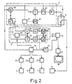
- Fig. 2 ein Blockschaltbild eines solchen Gerätes.
- Fig. 3 die Lage der Spektralkomponenten von Wasser, Milchsäure und Lipiden und
- Fig. 4 den zeitlichen Verlauf der erfindungsgemäßen Sequenzen.
- Fig. 1 is a magnetic resonance imaging device with which the inventive method can be carried out.
- Fig. 2 is a block diagram of such a device.
- Fig. 3 shows the location of the spectral components of water, lactic acid and lipids and
- 4 shows the time course of the sequences according to the invention.
Das in Fig. 1 schematisch dargestellte Kernspin-Untersuchungsgerät enthält eine aus vier Spulen 1 bestehende Anordnung zur Erzeugung eines homogenen stationären Magnetfeldes, das ausreichend stark sein muß und z.B. 4 Tesla beträgt. Dieses Feld verläuft in z-Richtung eines kartesischen Koordinatensystems. Die zur z-Achse konzentrisch angeordneten Spulen können auf einer Kugeloberfläche 2 angeordnet sein. Im Innern dieser Spulen befindet sich der zu untersuchende Patient 20.The nuclear spin examination device shown schematically in Fig. 1 contains an arrangement consisting of four
Zur Erzeugung eines in z-Richtung verlaufenden und sich in dieser Richtung linear ändernden Magnetfeldes Gz sind vier Spulen 3 vorzugsweise auf der gleichen Kugeloberfläche angeordnet. Weiterhin sind vier Spulen 7 vorgesehen, die ein ebenfalls in z-Richtung verlaufendes magnetisches Gradientenfeld (d.h. ein Magnetfeld, dessen Stärke sich in einer Richtung linear ändert) Gx erzeugen, dessen Gradient jedoch in x-Richtung verläuft. Ein in z-Richtung verlaufendes magnetisches Gradientenfeld Gy mit einem Gradienten in y-Richtung wird von vier Spulen 5 erzeugt, die die gleiche Form haben können wie die Spulen 7, die jedoch diesen gegenüber um 90° versetzt angeordnet sind. Von diesen vier Spulen sind in Figur 1 nur zwei dargestellt.In order to generate a magnetic field Gz running in the z direction and changing linearly in this direction, four
Da jede der drei Spulenanordnungen 3, 5 und 7 zur Erzeugung der magnetischen Gradientenfelder Gz, Gy und Gx symmetrisch zur Kugeloberfläche 2 angeordnet ist, ist die Feldstärke im Kugelzentrum, das gleichzeitig den Koordinatenursprung des erwähnten kartesischen xyz-Koordinatensystems bildet, nur durch das stationäre homogene Magnetfeld der Spulenanordnung 1 bestimmt. Weiterhin ist eine Hochfrequenzspule 11 symmetrisch zur Ebene z=0 des Koordinatensystems angeordnet, die so ausgebildet ist, daß damit ein im wesentlichen homogenes und in x-Richtung, d.h. senkrecht zur Richtung des stationären homogenen Magnetfeldes verlaufendes hochfrequentes Magnetfeld erzeugt wird. Der Hochfrequenzspule wird während jedes Hochfrequenzimpulses ein hochdrequenter modulierter Strom von einem Hochfrequenzgenerator zugeführt. Im Anschluß an eine Sequenz dient die Hochfrequenzspule 11 oder eine gesonderte Hochfrequenz-Empfangsspule zum Empfangen der im Untersuchungsbereich erzeugten Kernresonanzsignale.Since each of the three
Fig. 2 zeigt ein vereinfachtes Blockschaltbild dieses Kernspin-Untersuchungsgerätes. Die Hochfrequenzspule 11 ist über eine Umschalteinrichtung 12 einerseits an einen Hochfrequenzgenerator 4 und andererseits an einen Hochfrequenzempfänger 6 angeschlossen.2 shows a simplified block diagram of this nuclear spin examination device. The high-
Der Hochfrequenzgenerator 4 enthält einen in seiner Frequenz durch eine Steuereinheit 15 digital steuerbaren Hochfrequenzoszillator 40, der Schwingungen mit einer Frequenz entsprechend der Larmorfrequenz der anzuregenden Atomkerne bei der von den Spulen 1 erzeugten Feldstärke liefert. Die Larmorfrequenz f berechnet sich bekanntlich nach der Beziehung f = cB, wobei B die magnetische Induktion in dem stationären homogenen Magnetfeld darstellt und c das gyromagnetische Verhältnis, das beispielsweise für Protonen 42,56 MHz/T beträgt. Der Ausgang des Oszillators 40 ist mit einem Eingang einer Mischstufe 43verbunden. Der mischstufe wird ein zweites Eingangssignal von einem Digital-Analog-Wandler 44 zugeführt, dessen Ausgang mit einem digitalen Speicher 45 verbunden ist. Aus dem Speicher wird - gesteuert durch die Steuereinrichtung - eine Folge von ein Hüllkurvensignal darstellenden digitalen Datenworten ausgelesen.The high-
Die Mischstufe 43 verarbeitet die ihr zugeführten Eingangssignale so, daß sie an ihrem Ausgang die mit dem Hüllkurvensignal modulierte Trägerschwingung erscheint. Das Ausgangssignal der Mischstufe 43 wird über einen von der Steuereinrichtung 15 gesteuerten Schalter 46 einem Hochfrequenz-Leistungsverstärker 47 zugeführt, dessen Ausgang mit der Umschalteinrichtung 12 verbunden ist. Diese wird ebenfalls durch die Steuereinrichtung 15 gesteuert.The
Der Empfänger 6 enthält einen Hochfrequenzverstärker 60, der mit der Umschalteinrichtung verbunden ist und dem die in der Hochfrequenzspule 11 induzierten Kernresonanzsignale zugeführt werden, wobei die Umschalteinrichtung den entsprechenden Schaltzustand haben muß. Der Verstärker 60 besitzt einen von der Steuereinrichtung 15 gesteuerten Stummschalteingang, über den er gesperrt werden kann, so daß die Verstärkung praktisch Null ist. Der Ausgang des Verstärkers ist mit den ersten Eingängen zweier multipli kativer Mischstufen 61 und 62 verbunden, die jeweils ein dem Produkt ihrer Eingangssignale entsprechendes Ausgangssignal liefern. Den zweiten Eingängen der Mischstufen 61 und 62 wird ein Signal mit der Frequenz des Oszillators 40 zugeführt, wobei zwischen den Signalen an den beiden Eingängen eine Phasenverschiebung von 90° besteht. Diese Phasenverschiebung wird mit Hilfe eines 90° Phasendrehgliedes 48 erzeugt, dessen Ausgang mit dem Eingang der Mischstufe 62 und dessen Eingang mit dem Eingang der Mischstufe 61 und mit dem Ausgang des Oszillators 40 verbunden ist.The receiver 6 contains a high-
Die Ausgangssignale der Mischstufe 61 und 62 werden über Tiefpässe 63 und 64, die die vom Oszillator 40 gelieferte Frequenz sowie alle darüberliegenden frequenzen unterdrücken und niederfrequente Anteile durchlassen, je einem Analog-Digital-Wandler 65 bzw. 66 zugeführt. Dieser setzt die analogen Signale der einen Quadratur-Demodulator bildenden Schaltung 61..64 in digitale Datenworte um, die einem Speicher 14 zugeführt werden. Die Analog-Digital-Wandler 65 und 66 sowie der Speicher 14 erhalten ihre Taktimpulse von einem Taktimpulsgenerator 16, der über eine Steuerleitung von der Steuereinrichtung 15 blockiert bzw. freigegeben werden kann, so daß nur in einem durch die Steuereinrichtung 15 definierten Meßintervall diec von der Hochfrequenzspule 11 gelieferten, in den Niederfrequenzbereich transponierten Signale in eine Folge digitaler Datenworte umgesetzt und in dem Speicher 14 gespeichert werden können.The output signals of the
Die im Speicher 14 gespeicherten Datenworte werden einem Rechner 17 zugeführt, der daraus das Spektrum der Kernmagnetisierung ermittelt und an einer geeigneten Wiedergabeeinheit, z.B. einem Monitor 18, ausgibt.The data words stored in the
Fig. 3 zeigt die Lage der für die klinische Untersuchung wesentlichen Komponenten auf einer Frequenzskala, die die auf die Larmorfrequenz von TMS (Tetramethylsilan) normierte Frequenzabweichung gegenüber der Larmorfrequenz von TMS angibt. Die Larmorfrequenz von TMS liegt dabei also bei Null, während die Larmorfrequenz W von Wasser bei 4,7 ppm liegt. Die beiden miteinander gekoppelten Komponenten M1 und M2 der CH₃-Gruppe von Milchsäure bzw. Laktat liegen bei 4,1 ppm bzw. bei 1,3 ppm, während die entsprechenden Komponenten L1 und L2 der Lipide bei 1,4 und 0,9 liegen.3 shows the position of the components essential for the clinical examination on a frequency scale which indicates the frequency deviation normalized to the Larmor frequency of TMS (tetramethylsilane) compared to the Larmor frequency of TMS. The Larmor frequency of TMS is therefore zero, while the Larmor frequency W of water is 4.7 ppm. The two coupled components M1 and M2 of the CH₃ group of lactic acid and lactate are 4.1 ppm and 1.3 ppm, respectively, while the corresponding components L1 and L2 of the lipids are 1.4 and 0.9.
Der zeitliche Verlauf einer Sequenz ergibt sich aus Fig. 4, deren erste Zeile die zeitliche Lage der Hochfrequenzimpulse darstellt. Jede Sequenz umfaßt die drei Hochfrequenzimpulse HF1, HF2, HF3, vorzugsweise 90°-Impulse. Von diesen drei Hochfrequenzimpulsen ist einer schichtselektiv, vorzugsweise der erste. Die beiden anderen sind vorzugsweise frequenzselektiv. Die frequenzselektiven Hochfrequenzimpulse haben eine derart geringe Bandbreite, daß von dem in Fig. 3 dargestellten Spektrum nur die Milchsäurekomponente M2, die Lipidkomponenten L1, L2 sowie einige ungekoppelte Lipidkomponenten angeregt werden, nicht aber die Laktatkomponente M1 und die Wasserkomponente W. Das durch geeignete Gestaltung des aus dem Speicher 45 entnommenen Hüllkurvensignals nahezu rechteckförmige Frequenzspektrum dieser Hochfrequenzimpulse ist in Fig. 3 mit F angedeutet. Man erkennt, daß das Spektrum, das seine Mittenfrequenz bei 0,5 ppm hat und von -1 ppm bis +2 ppm erreicht, unsymmetrisch zu den anzuregenden Frequenzkomponenten (L1, M2, L2) liegt. Würde man stattdessen das Spektrum F symmetrisch zu den erwähnten Komponenten legen, dann müßten - bei gleichbleibender oberer Grenzfrequenz - die Hochfrequenzimpulse noch schmalbanbandiger sein und damit noch länger dauern.The time course of a sequence results from FIG. 4, the first line of which represents the time position of the high-frequency pulses. Each sequence comprises the three high-frequency pulses HF1, HF2, HF3, preferably 90 ° pulses. Of these three high-frequency pulses, one is slice-selective, preferably the first. The other two are preferably frequency selective. The frequency-selective high-frequency pulses have such a small bandwidth that only the lactic acid component M2, the lipid components L1, L2 and some uncoupled lipid components are excited from the spectrum shown in FIG. 3, but not the lactate component M1 and the water component W. This by suitable design of the Envelope signal taken from the
Bei der in Fig. 4 dargestellten Sequenz wirkt der erste Hochfrequenzimpuls HF1 schichtselektiv, weil während seiner Dauer ein magnetisches Gradientenfeld Gz2 wirksam ist (4. Zeile von Fig. 4). Die Hochfrequenzimpulse HF2 und HF3 sind frequenzselektiv und besitzen das Anregungsspektrum F (Fig. 3). Der erste Hochfrequenzimpuls HF1 regt innerhalb der Schicht nicht nur die Frequenzkomponenten im Spektralbereich F an, sondern auch die außerhalb liegenden Frequenzkomponenten, beispielsweise W und M1. Das durch diesen Hochfrequenzimpuls erzeugte FID-Signal, das u.a. auch von den Komponenten W und M1 beeinflußt wird, wird durch die im weiteren Verlauf der Sequenz folgenden magnetischen Gradientenfelder dephasiert, so daß zu dem Zeitpunkt, zu dem das von den drei Hochfrequenzimpulsen erzeugte stimulierte Echosignal auftritt, die auf W und M1 zurückzuführenden Anteile des Kernresonanzsignals praktisch verschwunden sind. Man kann statt des ersten Hochfrequenzimpulses auch den zweiten oder den dritten Hochfrequenzimpuls HF2 bzw. HF3 schichtselektiv und die beiden anderen frequenzselektiv machen, doch wird dann das FID-Signal des schichtselektiven Hochfrequenzimpulses weniger stark unterdrückt. Die in Fig. 1 dargestellte Variante mit dem schichtselektiven Hochfrequenzimpuls als ersten der drei Impulse wird daher bevorzugt.In the sequence shown in FIG. 4, the first high-frequency pulse HF1 acts slice-selectively because a magnetic gradient field Gz2 is active during its duration (4th line of FIG. 4). The high-frequency pulses HF2 and HF3 are frequency-selective and have the excitation spectrum F (FIG. 3). The first high-frequency pulse HF1 excites not only the frequency components in the spectral range F within the layer, but also the external frequency components, for example W and M1. The FID signal generated by this high-frequency pulse, which i.a. is also influenced by the components W and M1, is dephased by the magnetic gradient fields which follow in the further course of the sequence, so that at the point in time at which the stimulated echo signal generated by the three high-frequency pulses occurs, the portions of the nuclear magnetic resonance signal which can be attributed to W and M1 have practically disappeared. Instead of the first high-frequency pulse, the second or the third high-frequency pulse HF2 or HF3 can also be made slice-selective and the other two frequency-selective, but the FID signal of the slice-selective high-frequency pulse is then suppressed less strongly. The variant shown in FIG. 1 with the slice-selective high-frequency pulse as the first of the three pulses is therefore preferred.
Der zeitliche Abstand zwischen dem ersten Hochfrequenzimpuls HF1 und dem zweiten Hochfrequenzimpuls HF2 beträgt 1/2J, wobei J die skalare Kopplungskonstante von Milchsäure ist (ca. 7Hz), so daß sich ein zeitlicher Abstand von ca. 68 ms ergibt. Dadurch wird erreicht, daß die beiden Frequenzkomponenten, die infolge der J-Kopplung bei der Milchsäurekomponente M2 entstehen, zum Zeitpunkt des zweiten Hochfrequenzimpulses HF2 in Antiphase sind. Das gleiche gilt für die entsprechenden Anteile der Lipidkomponenten L1 und L2, weil deren Kopplungskonstante J etwa genauso groß ist wie die von Milchsäure.The time interval between the first high-frequency pulse HF1 and the second high-frequency pulse HF2 is 1/2 J, where J is the scalar coupling constant of lactic acid (approx. 7 Hz), so that there is a time interval of approx. 68 ms. It is thereby achieved that the two frequency components which arise as a result of the J coupling in the lactic acid component M2 are in antiphase at the time of the second high-frequency pulse HF2. The same applies to the corresponding proportions of the lipid components L1 and L2, because their coupling constant J is approximately is the same size as that of lactic acid.
Durch ein zwischen dem ersten und dem zweiten Hochfreimpuls wirksames magnetisches Gradientenfeld Gz3 wird erreicht, daß die Kernmagnetisierung innerhalb der Schicht ortsabhängig (in z-Richtung) variiert. Der zweite Hochfrequenzimpuls bewirkt dabei teilweise die Anregung von höheren Quantenzuständen, die kein beobachtbares Signal liefern und im übrigen den Transfer der Magnetisierung von M2 auf M1. Ebenso wird die Magnetisierung zwischen den Lipidgruppen transferiert. Während dabei der Transfer jedoch wechselseitig ist, ist er zwischen den Milchsäurekomponenten nur einseitig; da die Komponente M1 den zweiten Hochfrequenzimpuls nicht "sieht", erfolgt kein Transfer von M1 nach M2. Infolgedessen ist nach dem zweiten Hochfrequenzimpuls die Magnetisierung bei M2 verschwunden, nicht aber bei L1 und L2. Wenn man auf andere Weise dafür sorgt, daß kein Polarisationstransfer von M1 auf M2 stattfindet, z.B. indem man von vornherein die Komponente M1 zusammen mit der Wasserkomponente W unterdrückt, ist es nicht mehr erforderlich, daß die Hochfrequenzimpulse HF2 und HF3 frequenzselektiv sind. Sie können dann in gleicher Weise schichtselektiv sein wie der erste (HF1).By means of a magnetic gradient field Gz3 which is effective between the first and the second high-frequency pulse, the nuclear magnetization within the layer varies depending on the location (in the z direction). The second high-frequency pulse partially excites higher quantum states that do not provide an observable signal and, moreover, transfers the magnetization from M2 to M1. The magnetization is also transferred between the lipid groups. However, while the transfer is mutual, it is only one-sided between the lactic acid components; since component M1 does not "see" the second high-frequency pulse, there is no transfer from M1 to M2. As a result, after the second radio frequency pulse, the magnetization in M2 has disappeared, but not in L1 and L2. If you take care in another way that there is no polarization transfer from M1 to M2, e.g. by suppressing the component M1 together with the water component W from the outset, it is no longer necessary for the high-frequency pulses HF2 and HF3 to be frequency-selective. They can then be slice-selective in the same way as the first (HF1).
Nach dem dritten Hochfrequenzimpuls und vor dem Auftreten des stimulierten Echosignals wird ein magnetisches Gradientenfeld Gz5 eingeschaltet, dessen Gradient in der gleichen Richtung verläuft wie der des Feldes Gz 3 und dessen Amplitude und Dauer so gewählt sind, daß das zeitliche Integral über Gz3 genauso groß ist wie das über Gz5. Dadurch wird der Einfluß von Gz3 auf das stimulierte Echosignal beseitigt. Das stimulierte Echosignal tritt in einem zeitlichen Abstand von HF3 auf, der dem zeitlichen abstand zwischen HF1 und HF2 entspricht. Während des stimulierten Echosignals ist ein sogenannter Meß- bzw. Lesegradient Gx2 wirksam, dem ein Lesegradient Gx1 zwischen dem ersten und dem zweiten Hochfrequenzimpuls vorausgeht, dessen zeitliches Integral der Hälfte des zeitlichen Integrals über Gx2 entspricht (vergl. 2. Zeile von Fig. 4).After the third high-frequency pulse and before the occurrence of the stimulated echo signal, a magnetic gradient field Gz5 is switched on, the gradient of which runs in the same direction as that of the field Gz 3 and whose amplitude and duration are selected such that the time integral over Gz3 is as large as that about Gz5. This eliminates the influence of Gz3 on the stimulated echo signal. The stimulated echo signal occurs at a time interval from HF3, which corresponds to the time interval between HF1 and HF2. During the stimulated echo signal, a so-called measuring or reading gradient Gx2 is effective, which is preceded by a reading gradient Gx1 between the first and the second high-frequency pulse, the time integral of which corresponds to half the time integral via Gx2 (cf. 2nd line of FIG. 4).
Wie die 5. Zeile von Fig. 2 zeigt, wird während des Auftretens des stimulierten Echosignals der Taktgenerator 16 freigegeben, so daß das stimulierte Echosignal als Folge digitaler Datenworte in den Speicher 14 übernommen wird. Das stimulierte Echosignal wird von allen Komponenten innerhalb des Frequenzbereiches F beeinflußt - mit Ausnahme der Komponente M2.As the 5th line of FIG. 2 shows, the
Diese Sequenz wird nach einer geeigneten Repetitionszeit wiederholt mit dem einzigen Unterschied, daß genau in der Mitte zwischen dem ersten und dem zweiten Hochfrequenzimpuls ein in der ersten Zeile von Fig. 4 gestrichelt angedeuteter 180°-Hochfrequenzimpuls HF4 erzeugt wird, und daß nach dem dritten Hochfrequenzimpuls HF3 ein weiterer 180°-Hochfrequenzimpuls HF5 erzeugt wird, der von HF3 den gleichen Abstand hat wie HF4 von HF1. Diese Impulse sind ebenfalls frequenzselektiv und zwar derart, daß nur eine der Komponenten M1 bzw. M2 angeregt wird. Je nachdem, ob nur eine oder beide Komponenten einer J-Kopplung diese Impulse sehen oder nicht, wird die durch die J-Kopplung bewirkte Modulation refokussiert bzw. nicht refokussiert. Infolgedessen verläuft die Modulation der Komponenten L1 und L2 durch die J-Kopplung in gleicher Weise wie bei der ersten Sequenz (ohne HF4). Hingegen sind die Frequenzkomponenten der Milchsäurekomponente M2 zur Zeit des zweiten Hochfrequenzimpulses HF2 in Phase, tragen also zur Erzeugung eines normalen stimulierten Echos bei.This sequence is repeated after a suitable repetition time with the only difference that a 180 ° high-frequency pulse HF4 indicated in dashed lines in the first line of FIG. 4 is generated exactly in the middle between the first and the second high-frequency pulse, and that after the third high-frequency pulse HF3 a further 180 ° high-frequency pulse HF5 is generated, which has the same distance from HF3 as HF4 from HF1. These pulses are also frequency-selective in such a way that only one of the components M1 and M2 is excited. Depending on whether only one or both components of a J coupling see these pulses or not, the modulation caused by the J coupling is refocused or not refocused. As a result, the modulation of components L1 and L2 through the J coupling proceeds in the same way as in the first sequence (without HF4). On the other hand, the frequency components of the lactic acid component M2 are in phase at the time of the second high-frequency pulse HF2, and thus contribute to the generation of a normal stimulated echo.
Wenn dabei nur M2 angeregt wird, beispielsweise wenn HF4 das Spektrum F hat, kann das negative Einflüsse auf das stimulierte Echosignal haben, insbesondere wenn durch Gz3 keine vollständige Rephasierung erreicht wird. In dieser Hinsicht ist ein Frequenzspektrum, das nur die Komponente M1 anregt, nicht aber M2 (und L1, L2), günstiger. Zwar kann sich hierbei u.U. eine zusätzliche unerwünschte Anregung der Wasserkomponente W ergeben; da diese relativ gut zu unterdrücken ist, wird die letztgenannte Variante bevorzugt.If only M2 is excited, for example if HF4 has the spectrum F, this can have negative effects on the stimulated echo signal, in particular if Gz3 does not achieve complete rephasing. In this regard, a frequency spectrum that only excites component M1, but not M2 (and L1, L2), is more favorable. Under certain circumstances, result in an additional undesirable excitation of the water component W; since this is relatively easy to suppress, the latter variant is preferred.
Wie zuvor erläutert, beeinflussen die gekoppelten Lipid-Komponenten L1, L2 und die ungekoppelten Komponenten innerhalb des Bereiches F daher das stimulierte Echosignal bei der zweiten Sequenz in genau der gleichen Weise wie bei der ersten Sequenz; jedoch liefert die Milchsäurekomponente M2 bei der zweiten Sequenz einen Beitrag zum stimulierten Echosignal im Gegensatz zur ersten Sequenz. Subtrahiert man daher die beiden stimulierten Echosignale voneinander, dann wird die Differenz nur noch von der Milchsäurekomponente M2 bestimmt. Es ist daher möglich, die Milchsäureverteilung in der Schicht darzustellen.As previously explained, the coupled lipid components L1, L2 and the uncoupled components within the region F therefore influence the stimulated echo signal in the second sequence in exactly the same way as in the first sequence; however, the lactic acid component M2 in the second sequence contributes to the stimulated echo signal in contrast to the first sequence. Therefore, if the two stimulated echo signals are subtracted from each other, the difference is only determined by the lactic acid component M2. It is therefore possible to show the lactic acid distribution in the layer.
Zu diesem Zweck werden die beiden Sequenzen mehrfach wiederholt, wobei jedesmal ein magnetisches Gradientenfeld (Gy, 3. Zeile), das senkrecht zum Lesegradienten (Gx, 2. Zeile) und senkrecht zu dem Schichtselektionsgradienten (Gz, 4. Zeile) verläuft, d.h. in y-Richtung in seiner Amplitude variiert wird. Das Ganze kann dann zur Verbesserung des Signal-Rausch-Verhältnisses noch mehrfach wiederholt werden.For this purpose, the two sequences are repeated several times, each time with a magnetic gradient field (Gy, 3rd line) that runs perpendicular to the reading gradient (Gx, 2nd line) and perpendicular to the slice selection gradient (Gz, 4th line), i.e. its amplitude is varied in the y direction. The whole thing can then be repeated several times to improve the signal-to-noise ratio.
Zur Rekonstruktion der Milchsäureverteilung in der angeregten Schicht gibt es verschiedene Möglichkeiten. Man könnte ein erstes Bild aus den stimulierten Echosignalen der ersten Sequenzen und ein zweites Bild aus den stimulierten Echosignalen der zweiten Sequenzen erzeugen und die beiden Bilder voneinander subtrahieren. Einfacher hinsichtlich des Rechen- und Speicheraufwandes ist es jedoch, die stimulierten Echosignale der ersten und der zweiten Sequenz, die dem gleichen Phasencodierungsgradienten zugeordnet sind, unmittelbar voneinander zu subtrahieren und die so gebildeten Differenzsignale einer zweidimensionalen Fouriertransformation zu unterziehen.There are various options for reconstructing the lactic acid distribution in the excited layer. You could get a first picture from the stimulated echo signals of the first sequences and generate a second image from the stimulated echo signals of the second sequences and subtract the two images from one another. However, it is simpler in terms of the computation and storage effort to directly subtract the stimulated echo signals of the first and the second sequence, which are assigned to the same phase coding gradient, and to subject the difference signals thus formed to a two-dimensional Fourier transformation.
Die schematische Darstellung von Fig. 3 verdeckt, daß im menschlichen Körper die Komponente W dominierend ist, weil die Konzentration der an Wasser gebundenen Protonen um mehrere Zenerpotenzen höher ist als die Konzentration beispielsweise der an die Milchsäurekomponente M2 gebundenen Protonen. Wenn das Frequenzspektrum der frequenzselektiven Impulse HF2 und HF3 nicht dem in Fig. 3 idealisiert dargestellten Spektrum entspricht, sondern so gestaltet ist, daß - wenn auch in stark abgeschwächter Form - auch die Wasserkomponente angeregt werden kann, kann das stimulierte Echosignal wesentlich von dieser Komponente bestimmt werden. Um diese Komponente weitgehend zu unterdrücken, kann vor dem ersten Hochfrequenzimpuls HF1 und/oder zwischen dem zweiten und dem dritten Hochfrequenzimpuls HF2 bzw. HF3 ein auf die Resonanzlinie der Wasserkomponente abgestimmter frequenzselektiver Impuls HF6 bzw. HF7 jeweils gefolgt von einem magnetischen Gradientenfeld (Gz1 bzw. Gz4) erzeugt werden, das die dadurch angeregten Wasserkomponenten dephasiert, so daß deren Einfluß auf das stimulierte Echosignal stark herabgesetzt wird.3 conceals the fact that component W is dominant in the human body because the concentration of protons bound to water is several zener powers higher than the concentration, for example, of protons bound to lactic acid component M2. If the frequency spectrum of the frequency-selective pulses HF2 and HF3 does not correspond to the spectrum idealized in FIG. 3, but is designed in such a way that the water component can be stimulated, albeit in a greatly weakened form, the stimulated echo signal can be essentially determined by this component will. In order to largely suppress this component, a frequency-selective pulse HF6 or HF7 matched to the resonance line of the water component can be followed by a magnetic gradient field (Gz1 and / or between the second and third high-frequency pulse HF2 or HF3, respectively) before the first high-frequency pulse HF1 and / or Gz4) are generated, which dephases the water components excited thereby, so that their influence on the stimulated echo signal is greatly reduced.
Im Ausführungsbeispiel sind die frequenzselektiven Hochfrequenzimpulse HF6 und HF7 sogenannte binomiale Hochfrequenzimpulse, die aus mehreren Teilpulsen bestehen, deren Amplituden im gleichen Verhältnis zueinander stehen wie die Binomialkoeffizienten und deren zeitliche Abstände bzw. deren Mittenfrequenz im Hinblick auf die Anregung der Wasserkomponente optimiert sind. Es können jedoch auch andere Impulse benutzt werden, z.B. sogenannte DANTE-Impulse.In the exemplary embodiment, the frequency-selective high-frequency pulses HF6 and HF7 are so-called binomial high-frequency pulses, which consist of a plurality of partial pulses Amplitudes are in the same relationship to one another as the binomial coefficients and their time intervals or their center frequency are optimized with regard to the excitation of the water component. However, other pulses can also be used, for example so-called DANTE pulses.
Wenn die Wasserkomponente W unterdrückt ist, ist in der Regel auch die Milchsäurekomponente M1 unterdrückt. Da dann ein Polarisationstransfer zwischen M1 und M2 nicht mehr möglich ist, müssen in diesem Fall die Hochfrequenzimpulse HF2 und HF3 nicht frequenzselektiv sein. Sie könnnen also auch breitbandiger sein. Um die Signalverarbeitung zu erleichtern, sollten sie dann aber in gleicher Weise schichtselektiv sein wie HF1; d.h. in ihrer Anwesenheit müßte ein in z-Richtung verlaufendes magnetisches Gradientenfeld (wie Gz2) erzeugt werden.If the water component W is suppressed, the lactic acid component M1 is usually also suppressed. Since then a polarization transfer between M1 and M2 is no longer possible, the high-frequency pulses HF2 and HF3 need not be frequency-selective in this case. So they can also be broadband. In order to facilitate signal processing, they should then be layer-selective in the same way as HF1; i.e. in their presence, a magnetic gradient field (such as Gz2) running in the z direction would have to be generated.
Claims (6)
dadurch gekennzeichnet, daß von den drei Hochfrequenzimpulsen der erste (HF1) schichtselektiv und die beiden folgenden (HF2 und HF3) frequenzselektiv sind.2. The method according to claim 1,
characterized in that of the three high-frequency pulses, the first (HF1) is slice-selective and the two following (HF2 and HF3) are frequency-selective.
dadurch gekennzeichnet, daß die beiden 180°-Hochfrequenzimpulse (HF4, HF5) von den gekoppelten Milchsäurekomponenten (M1,M2) nur die der Wasserkomponente (W) benachbarte (M1) Komponente angeregt wird.3. The method according to claim 1,
characterized in that the two 180 ° high-frequency pulses (HF4, HF5) are excited by the coupled lactic acid components (M1, M2) only the component (M1) adjacent to the water component (W).
dadurch gekennzeichnet, daß in jeder Sequenz vor dem ersten und/oder zwischen dem zweiten und dem dritten Hochfrequenzimpuls ein selektiv nur die an Wasser gebundenen Protonen anregender Hochfrequenzimpuls (HF5 bzw. HF6), gefolgt von einem der Dephasierung dienenden magnetischen magnetischen Gradientenfeld (Gz1 bzw. Gz4), erzeugt wird.4. The method according to claim 1 or 2,
characterized in that in each sequence before the first and / or between the second and the third high-frequency pulse, a high-frequency pulse (HF5 or HF6) which selectively only excites water-bound protons, followed by a magnetic gradient field (Gz1 or Gz4) is generated.
dadurch gekennzeichnet, daß die Mittenfrequenz der frequenzselektiven Impulse (HF2, HF3) unterhalb der Larmorfrequenzen der gekoppelten Lipid- und Milchsäurekomponenten liegt.5. The method according to claim 2,
characterized in that the center frequency of the frequency-selective pulses (HF2, HF3) lies below the Larmor frequencies of the coupled lipid and lactic acid components.
Applications Claiming Priority (2)
| Application Number | Priority Date | Filing Date | Title |
|---|---|---|---|
| DE3920433 | 1989-06-22 | ||
| DE3920433A DE3920433A1 (en) | 1989-06-22 | 1989-06-22 | NUCLEAR RESONANCE METHOD |
Publications (2)
| Publication Number | Publication Date |
|---|---|
| EP0404248A2 true EP0404248A2 (en) | 1990-12-27 |
| EP0404248A3 EP0404248A3 (en) | 1991-08-14 |
Family
ID=6383318
Family Applications (1)
| Application Number | Title | Priority Date | Filing Date |
|---|---|---|---|
| EP19900201578 Withdrawn EP0404248A3 (en) | 1989-06-22 | 1990-06-18 | N.m.r. imaging method |
Country Status (4)
| Country | Link |
|---|---|
| US (1) | US5121059A (en) |
| EP (1) | EP0404248A3 (en) |
| JP (1) | JPH0337043A (en) |
| DE (1) | DE3920433A1 (en) |
Cited By (1)
| Publication number | Priority date | Publication date | Assignee | Title |
|---|---|---|---|---|
| EP0496447B1 (en) * | 1991-01-24 | 1997-07-23 | Philips Patentverwaltung GmbH | NMR spectroscopy method and apparatus for carrying out the method |
Families Citing this family (14)
| Publication number | Priority date | Publication date | Assignee | Title |
|---|---|---|---|---|
| US5317261A (en) * | 1991-05-27 | 1994-05-31 | U.S. Philips Corporation | Volume-selective magnetic resonance imaging method and device |
| DE4232731C2 (en) * | 1992-06-16 | 2001-10-31 | Bruker Medizintech | NMR imaging method with single point recording (SPI) and measuring sequence |
| US5677626A (en) * | 1993-04-27 | 1997-10-14 | Kabushiki Kaisha Toshiba | System for magnetic resonance imaging |
| JPH114716A (en) | 1997-06-17 | 1999-01-12 | Mitsubishi Heavy Ind Ltd | Grip member, toothbrush and western tableware utilizing this |
| DE19750214C2 (en) * | 1997-11-13 | 1999-12-30 | Univ Ludwigs Albert | Process for generating nuclear spin spectroscopic signals by spatial modulation of z-magnetization |
| JP4509336B2 (en) * | 2000-08-31 | 2010-07-21 | 株式会社東芝 | Magnetic resonance equipment |
| US6987997B1 (en) * | 2003-06-18 | 2006-01-17 | General Electric Company | Method and apparatus for improved metabolite signal separation in MR spectroscopy |
| JP3992674B2 (en) * | 2003-09-25 | 2007-10-17 | ジーイー・メディカル・システムズ・グローバル・テクノロジー・カンパニー・エルエルシー | Magnetic resonance imaging device |
| RU2369406C2 (en) * | 2004-07-30 | 2009-10-10 | Джи-И Хелткер АС | Visualisation technique to distinguish healthy tissue from tumor tissue |
| US8970217B1 (en) | 2010-04-14 | 2015-03-03 | Hypres, Inc. | System and method for noise reduction in magnetic resonance imaging |
| US9864033B1 (en) * | 2013-08-26 | 2018-01-09 | University Of New Brunswick | Free induction decay based magnetic resonance imaging methods |
| US10901058B2 (en) | 2016-02-05 | 2021-01-26 | The Trustees Of The University Of Pennsylvania | Chemical exchange saturation transfer (CEST) imaging of lactate (LATEST) |
| US11938200B2 (en) | 2016-02-05 | 2024-03-26 | The Trustees Of The University Of Pennsylvania | Non-nutritive sweeteners and polyols as imaging agents |
| CN109187613B (en) * | 2018-09-07 | 2019-10-18 | 厦门大学 | A kind of nuclear magnetic resonance multidimensional spectral method measuring specific proton hydrogen-hydrogen coupling constant |
Citations (6)
| Publication number | Priority date | Publication date | Assignee | Title |
|---|---|---|---|---|
| EP0184840A1 (en) * | 1984-12-14 | 1986-06-18 | Max-Planck-Gesellschaft zur Förderung der Wissenschaften e.V. | Arrangement for the spatially resolved inspection of a sample by means of magnetic resonance of spin moments |
| US4680546A (en) * | 1986-01-27 | 1987-07-14 | General Electric Company | Methods of, and pulse sequences for, the supression of undesired resonances by generation of quantum coherence in NMR imaging and spectroscopy |
| US4703270A (en) * | 1986-04-18 | 1987-10-27 | The University Of British Columbia | Zero quantum NMR imaging and spectroscopy in a low homogeneity magnetic field |
| EP0244752A2 (en) * | 1986-05-05 | 1987-11-11 | General Electric Company | Suppression of non-coupled spins in NMR imaging and spectroscopy |
| EP0278254A1 (en) * | 1987-01-30 | 1988-08-17 | Siemens Aktiengesellschaft | Apparatus for determining nuclear magnetic resonance spectra from spatially selectable regions of an object under examination |
| EP0370333A2 (en) * | 1988-11-25 | 1990-05-30 | General Electric Company | NMR imaging of metabolites using a multiple quantum excitation sequence |
Family Cites Families (2)
| Publication number | Priority date | Publication date | Assignee | Title |
|---|---|---|---|---|
| DE3804924A1 (en) * | 1988-02-17 | 1989-08-31 | Philips Patentverwaltung | METHOD FOR DETERMINING THE SPECTRAL DISTRIBUTION OF CORE MAGNETIZATION IN A LIMITED VOLUME RANGE AND ARRANGEMENT FOR IMPLEMENTING THE METHOD |
| US4962357A (en) * | 1988-07-07 | 1990-10-09 | Sotak Christopher H | Two-dimensional method for spectral editing of NMR signals produced by metabolites containing coupled spins |
-
1989
- 1989-06-22 DE DE3920433A patent/DE3920433A1/en not_active Withdrawn
-
1990
- 1990-06-13 US US07/539,408 patent/US5121059A/en not_active Expired - Fee Related
- 1990-06-18 EP EP19900201578 patent/EP0404248A3/en not_active Withdrawn
- 1990-06-19 JP JP2161177A patent/JPH0337043A/en active Pending
Patent Citations (6)
| Publication number | Priority date | Publication date | Assignee | Title |
|---|---|---|---|---|
| EP0184840A1 (en) * | 1984-12-14 | 1986-06-18 | Max-Planck-Gesellschaft zur Förderung der Wissenschaften e.V. | Arrangement for the spatially resolved inspection of a sample by means of magnetic resonance of spin moments |
| US4680546A (en) * | 1986-01-27 | 1987-07-14 | General Electric Company | Methods of, and pulse sequences for, the supression of undesired resonances by generation of quantum coherence in NMR imaging and spectroscopy |
| US4703270A (en) * | 1986-04-18 | 1987-10-27 | The University Of British Columbia | Zero quantum NMR imaging and spectroscopy in a low homogeneity magnetic field |
| EP0244752A2 (en) * | 1986-05-05 | 1987-11-11 | General Electric Company | Suppression of non-coupled spins in NMR imaging and spectroscopy |
| EP0278254A1 (en) * | 1987-01-30 | 1988-08-17 | Siemens Aktiengesellschaft | Apparatus for determining nuclear magnetic resonance spectra from spatially selectable regions of an object under examination |
| EP0370333A2 (en) * | 1988-11-25 | 1990-05-30 | General Electric Company | NMR imaging of metabolites using a multiple quantum excitation sequence |
Cited By (1)
| Publication number | Priority date | Publication date | Assignee | Title |
|---|---|---|---|---|
| EP0496447B1 (en) * | 1991-01-24 | 1997-07-23 | Philips Patentverwaltung GmbH | NMR spectroscopy method and apparatus for carrying out the method |
Also Published As
| Publication number | Publication date |
|---|---|
| EP0404248A3 (en) | 1991-08-14 |
| DE3920433A1 (en) | 1991-01-03 |
| US5121059A (en) | 1992-06-09 |
| JPH0337043A (en) | 1991-02-18 |
Similar Documents
| Publication | Publication Date | Title |
|---|---|---|
| EP0226247A2 (en) | Method for nuclear spin tomography and arrangement for carrying out the method | |
| EP0404248A2 (en) | N.M.R. imaging method | |
| EP0789251B1 (en) | MR method for determining magnetic field inhomogeneity over the examining region and MR apparatus for carrying out the method | |
| EP0412602B1 (en) | NMR spectroscopic method and apparatus for using it | |
| EP0357100A2 (en) | Nuclear resonance tomography process, and nuclear resonance tomograph for performing the process | |
| EP0322006A2 (en) | Nuclear magnetic resonance spectroscopy technique | |
| EP0329240A2 (en) | Method for determining the spectral distribution of nuclear magnetization in a limited range of the volume, and apparatus for carrying out the method | |
| EP0259935A2 (en) | Nuclear spin tomography method and nuclear spin tomograph for carrying out the method | |
| DE3937428A1 (en) | Nuclear spin tomography method for generating separated fat and water images and arrangement for carrying out the method | |
| DE3938370A1 (en) | Nuclear spin tomography method and nuclear spin tomography for performing the method | |
| DE3542215A1 (en) | Nuclear spin tomography method and arrangement for carrying out the method | |
| EP0496447B1 (en) | NMR spectroscopy method and apparatus for carrying out the method | |
| EP0369538B1 (en) | Nuclear spin tomography method for determining the nuclear magnetization in a number of parallel slices | |
| EP0478030B1 (en) | Method for two dimensional NMR spectroscopy | |
| EP0233675B1 (en) | Method for determining the spectral distribution of nuclear magnetization in a limited region of the volume, and apparatus for carrying out the method | |
| EP0392574A2 (en) | Procedure for the localized nuclear magnetic resonance spectroscopy and equipment for the working of the procedure | |
| EP0232945A2 (en) | Method for determining a nuclear magnetization distribution in a layer of a region of examination, and a nuclear spin tomograph for carrying out the method | |
| EP0261743A2 (en) | Method for determining the spectral distribution of nuclear magnetization in a limited region of the volume | |
| EP0248469B1 (en) | Nuclear spin tomography method | |
| DE3701849A1 (en) | METHOD AND DEVICE FOR NUCLEAR SPIN TOMOGRAPHY | |
| EP0237105A2 (en) | Method for determining the spectral distribution of nuclear magnetization in a limited region of the volume | |
| EP0467467A2 (en) | Nuclear magnetic resonance spectroscopy procedure | |
| EP0795758A1 (en) | Method of MR spectroscopy | |
| DE3729306A1 (en) | Method for determining the nuclear magnetisation distribution in a layer of a region under examination and NMR tomograph for carrying out the method | |
| DE3824274A1 (en) | Nuclear magnetic resonance examination method and arrangement for carrying out the method |
Legal Events
| Date | Code | Title | Description |
|---|---|---|---|
| PUAI | Public reference made under article 153(3) epc to a published international application that has entered the european phase |
Free format text: ORIGINAL CODE: 0009012 |
|
| AK | Designated contracting states |
Kind code of ref document: A2 Designated state(s): DE FR GB |
|
| PUAL | Search report despatched |
Free format text: ORIGINAL CODE: 0009013 |
|
| AK | Designated contracting states |
Kind code of ref document: A3 Designated state(s): DE FR GB |
|
| 17P | Request for examination filed |
Effective date: 19920214 |
|
| STAA | Information on the status of an ep patent application or granted ep patent |
Free format text: STATUS: THE APPLICATION HAS BEEN WITHDRAWN |
|
| 18W | Application withdrawn |
Withdrawal date: 19920711 |