EP0404888B1 - Plastic lens compositions and apparatus for the production thereof - Google Patents
Plastic lens compositions and apparatus for the production thereof Download PDFInfo
- Publication number
- EP0404888B1 EP0404888B1 EP89912757A EP89912757A EP0404888B1 EP 0404888 B1 EP0404888 B1 EP 0404888B1 EP 89912757 A EP89912757 A EP 89912757A EP 89912757 A EP89912757 A EP 89912757A EP 0404888 B1 EP0404888 B1 EP 0404888B1
- Authority
- EP
- European Patent Office
- Prior art keywords
- composition
- lens
- mould
- bis
- functional monomer
- Prior art date
- Legal status (The legal status is an assumption and is not a legal conclusion. Google has not performed a legal analysis and makes no representation as to the accuracy of the status listed.)
- Expired - Lifetime
Links
- 0 CC(C)(c1ccc(*=C)cc1)c1ccc(*=*)cc1 Chemical compound CC(C)(c1ccc(*=C)cc1)c1ccc(*=*)cc1 0.000 description 1
Images


Classifications
-
- C—CHEMISTRY; METALLURGY
- C08—ORGANIC MACROMOLECULAR COMPOUNDS; THEIR PREPARATION OR CHEMICAL WORKING-UP; COMPOSITIONS BASED THEREON
- C08F—MACROMOLECULAR COMPOUNDS OBTAINED BY REACTIONS ONLY INVOLVING CARBON-TO-CARBON UNSATURATED BONDS
- C08F18/00—Homopolymers and copolymers of compounds having one or more unsaturated aliphatic radicals, each having only one carbon-to-carbon double bond, and at least one being terminated by an acyloxy radical of a saturated carboxylic acid, of carbonic acid or of a haloformic acid
- C08F18/24—Esters of carbonic or haloformic acids
-
- B—PERFORMING OPERATIONS; TRANSPORTING
- B29—WORKING OF PLASTICS; WORKING OF SUBSTANCES IN A PLASTIC STATE IN GENERAL
- B29C—SHAPING OR JOINING OF PLASTICS; SHAPING OF MATERIAL IN A PLASTIC STATE, NOT OTHERWISE PROVIDED FOR; AFTER-TREATMENT OF THE SHAPED PRODUCTS, e.g. REPAIRING
- B29C33/00—Moulds or cores; Details thereof or accessories therefor
- B29C33/0038—Moulds or cores; Details thereof or accessories therefor with sealing means or the like
-
- B—PERFORMING OPERATIONS; TRANSPORTING
- B29—WORKING OF PLASTICS; WORKING OF SUBSTANCES IN A PLASTIC STATE IN GENERAL
- B29C—SHAPING OR JOINING OF PLASTICS; SHAPING OF MATERIAL IN A PLASTIC STATE, NOT OTHERWISE PROVIDED FOR; AFTER-TREATMENT OF THE SHAPED PRODUCTS, e.g. REPAIRING
- B29C35/00—Heating, cooling or curing, e.g. crosslinking or vulcanising; Apparatus therefor
- B29C35/02—Heating or curing, e.g. crosslinking or vulcanizing during moulding, e.g. in a mould
- B29C35/08—Heating or curing, e.g. crosslinking or vulcanizing during moulding, e.g. in a mould by wave energy or particle radiation
- B29C35/0888—Heating or curing, e.g. crosslinking or vulcanizing during moulding, e.g. in a mould by wave energy or particle radiation using transparant moulds
-
- B—PERFORMING OPERATIONS; TRANSPORTING
- B29—WORKING OF PLASTICS; WORKING OF SUBSTANCES IN A PLASTIC STATE IN GENERAL
- B29C—SHAPING OR JOINING OF PLASTICS; SHAPING OF MATERIAL IN A PLASTIC STATE, NOT OTHERWISE PROVIDED FOR; AFTER-TREATMENT OF THE SHAPED PRODUCTS, e.g. REPAIRING
- B29C43/00—Compression moulding, i.e. applying external pressure to flow the moulding material; Apparatus therefor
- B29C43/32—Component parts, details or accessories; Auxiliary operations
-
- B—PERFORMING OPERATIONS; TRANSPORTING
- B29—WORKING OF PLASTICS; WORKING OF SUBSTANCES IN A PLASTIC STATE IN GENERAL
- B29D—PRODUCING PARTICULAR ARTICLES FROM PLASTICS OR FROM SUBSTANCES IN A PLASTIC STATE
- B29D11/00—Producing optical elements, e.g. lenses or prisms
- B29D11/00009—Production of simple or compound lenses
- B29D11/00413—Production of simple or compound lenses made by moulding between two mould parts which are not in direct contact with one another, e.g. comprising a seal between or on the edges
-
- B—PERFORMING OPERATIONS; TRANSPORTING
- B29—WORKING OF PLASTICS; WORKING OF SUBSTANCES IN A PLASTIC STATE IN GENERAL
- B29D—PRODUCING PARTICULAR ARTICLES FROM PLASTICS OR FROM SUBSTANCES IN A PLASTIC STATE
- B29D11/00—Producing optical elements, e.g. lenses or prisms
- B29D11/00009—Production of simple or compound lenses
- B29D11/00432—Auxiliary operations, e.g. machines for filling the moulds
- B29D11/00442—Curing the lens material
-
- B—PERFORMING OPERATIONS; TRANSPORTING
- B29—WORKING OF PLASTICS; WORKING OF SUBSTANCES IN A PLASTIC STATE IN GENERAL
- B29D—PRODUCING PARTICULAR ARTICLES FROM PLASTICS OR FROM SUBSTANCES IN A PLASTIC STATE
- B29D11/00—Producing optical elements, e.g. lenses or prisms
- B29D11/00009—Production of simple or compound lenses
- B29D11/0048—Moulds for lenses
- B29D11/00528—Consisting of two mould halves joined by an annular gasket
-
- G—PHYSICS
- G02—OPTICS
- G02B—OPTICAL ELEMENTS, SYSTEMS OR APPARATUS
- G02B1/00—Optical elements characterised by the material of which they are made; Optical coatings for optical elements
- G02B1/04—Optical elements characterised by the material of which they are made; Optical coatings for optical elements made of organic materials, e.g. plastics
- G02B1/041—Lenses
-
- B—PERFORMING OPERATIONS; TRANSPORTING
- B29—WORKING OF PLASTICS; WORKING OF SUBSTANCES IN A PLASTIC STATE IN GENERAL
- B29C—SHAPING OR JOINING OF PLASTICS; SHAPING OF MATERIAL IN A PLASTIC STATE, NOT OTHERWISE PROVIDED FOR; AFTER-TREATMENT OF THE SHAPED PRODUCTS, e.g. REPAIRING
- B29C35/00—Heating, cooling or curing, e.g. crosslinking or vulcanising; Apparatus therefor
- B29C35/02—Heating or curing, e.g. crosslinking or vulcanizing during moulding, e.g. in a mould
- B29C35/08—Heating or curing, e.g. crosslinking or vulcanizing during moulding, e.g. in a mould by wave energy or particle radiation
- B29C35/0805—Heating or curing, e.g. crosslinking or vulcanizing during moulding, e.g. in a mould by wave energy or particle radiation using electromagnetic radiation
- B29C2035/0827—Heating or curing, e.g. crosslinking or vulcanizing during moulding, e.g. in a mould by wave energy or particle radiation using electromagnetic radiation using UV radiation
-
- B—PERFORMING OPERATIONS; TRANSPORTING
- B29—WORKING OF PLASTICS; WORKING OF SUBSTANCES IN A PLASTIC STATE IN GENERAL
- B29C—SHAPING OR JOINING OF PLASTICS; SHAPING OF MATERIAL IN A PLASTIC STATE, NOT OTHERWISE PROVIDED FOR; AFTER-TREATMENT OF THE SHAPED PRODUCTS, e.g. REPAIRING
- B29C37/00—Component parts, details, accessories or auxiliary operations, not covered by group B29C33/00 or B29C35/00
- B29C37/005—Compensating volume or shape change during moulding, in general
-
- Y—GENERAL TAGGING OF NEW TECHNOLOGICAL DEVELOPMENTS; GENERAL TAGGING OF CROSS-SECTIONAL TECHNOLOGIES SPANNING OVER SEVERAL SECTIONS OF THE IPC; TECHNICAL SUBJECTS COVERED BY FORMER USPC CROSS-REFERENCE ART COLLECTIONS [XRACs] AND DIGESTS
- Y10—TECHNICAL SUBJECTS COVERED BY FORMER USPC
- Y10S—TECHNICAL SUBJECTS COVERED BY FORMER USPC CROSS-REFERENCE ART COLLECTIONS [XRACs] AND DIGESTS
- Y10S425/00—Plastic article or earthenware shaping or treating: apparatus
- Y10S425/808—Lens mold
Definitions
- This invention relates generally to plastic lens compositions and methods and apparatus for making plastic lenses, and more particularly relates to a composition for making corrective or plano plastic lenses for use in eyeglasses and the like.
- Optical lenses have been produced from the polymer of diethylene glycol bis(allyl)-carbonate (DEG-BAC) by thermal curing techniques. These techniques for polymerizing DEG-BAC to produce an optical lens, however, have several disadvantages and drawbacks. One of the most significant drawbacks is that it takes approximately 12 hours to produce a lens according to this technique and therefore a lens forming mould can produce at most two lenses per day.
- DEG-BAC diethylene glycol bis(allyl)-carbonate
- the thermal curing process employs a thermal catalyst so that the polymerizable mixture of DEG-BAC and catalyst will slowly polymerize even while refrigerated.
- the polymerizable mixture therefore has a very short shelf life and must be used within a short time or it will harden in its container.
- thermal catalysts utilized in these procedures are quite volatile and dangerous to work with requiring extreme care in handling.
- the polymer of DEG-BAC exhibits desirable optical and mechanical properties. These properties include high light transmission, high clarity, and high index of refraction together with high abrasion and impact resistance. These properties in the past made DEG-BAC one of the leading monomers in the manufacture of high quality lenses. Other properties of DEG-BAC, however, such as its slow rate of polymerization make it an undesirable monomer in the manufacture of these items.
- US-A-4622376 discloses a pourable, polymerisable composition
- a pourable, polymerisable composition comprising an aromatic-containing poly (allyl carbonate)-functional material, styrenic material and a monomer having three or more allyl, methallyl, acrylyl and/or methacrylyl groups which may be free radically polymerised to produce polymerizates having high refractive index, high hardness and low yellowness.
- US-A-4742133 discloses a liquid monomer composition comprising at least one poly (allyl) carbonate-functional monomer which may be contacted with molecular oxygen to produce a liquid intermediate composition which is then heated to produce a polymerisable substantially gel-free composition.
- compositions of both US-A-4622376 and US-A-4742133 may be used to make an ophthalmic lens.
- EP-A-346,996 relates to a process for preparing organic glasses in which a liquid composition is utilised which contains one or more allyl carbonate monomers, and a photoinitiator in combination with limited amounts of a vinyl ester monomer and/or with an organic peroxide.
- a polymerisable composition for use in making substantially clear plastic lenses for use in eyeglasses by exposing the composition to ultraviolet light to cure the composition in a time period of less than one hour, the composition comprising at least a bis (allyl carbonate) functional monomer and additives comprising at least one polyethylenic-functional monomer containing at least two ethylenically unsaturated groups selected from acrylyl and methacrylyl, and a photoinitiator, wherein the bis (allyl carbonate) functional monomer comprises an aromatic-containing bis (allyl carbonate) functional monomer, or diethylene glycol allyl carbonate.
- a polymerisable composition for use in making substantially clear plastic lenses for use in eyeglasses by exposing the composition to ultraviolet light to cure the composition in a time period of approximately 30 minutes or less, the composition comprising at least a bis (allyl carbonate) functional monomer and additives comprising at least one polyethylenic-functional monomer containing at least two ethylenically unsaturated groups selected from acrylyl and methacrylyl, and a photoinitiator, wherein the bis (allyl carbonate) functional monomer comprises an aromatic-containing bis (allyl carbonate) functional monomer, or diethylene glycol allyl carbonate.
- a polymerisable composition for use in making substantially clear plastic lenses for use in eyeglasses by exposing the composition to ultraviolet light to cure the composition in a time period of approximately 15 to 30 minutes, the composition comprising at least a bis (allyl carbonate) functional monomer and additives comprising at least one polyethylenic-functional monomer containing at least two ethylenically unsaturated groups selected from acrylyl and methacrylyl, and a photoinitiator, wherein the bis (allyl carbonate) functional monomer comprises an aromatic-containing bis (allyl carbonate) functional monomer, or diethylene glycol bis allyl carbonate.
- aromatic-containing bis (allyl carbonate) functional monomer comprises bisphenol A bis (allyl carbonate).
- the functional monomer which may be the bisphenol A bis (allyl carbonate), comprises 30 weight % or less of the composition.
- the said polyethylenic-functional monomer contains three ethylenically unsaturated groups selected from acrylyl and methacrylyl.
- the said polyethylenic-functional monomer comprises 1,6 hexanedioldiacrylate.
- the said polyethylenic-functional monomer comprises tetraethylene glycol diacrylate.
- the said polyethylenic-functional monomer comprises tripropylene glycol diacrylate.
- the polyethylenic-functional monomer comprises trimethylolpropane triacrylate.
- the composition comprises a mould release agent.
- An embodiment also relates to the use of a composition as described above to form a substantially clear plastic lenses substantially free of distortions, cracks, patterns and striations for use in eye-glasses.
- An embodiment also relates to the use of a composition as described above to form a lens for use in eyeglasses having negligible yellowing.
- the invention additionally relates to a method of making a lens for use in eyeglasses which method comprises the step of using the composition as described above.
- the composition is cured to form a substantially clear lens for use in eyeglasses by being exposed to ultraviolet light while in a mould cavity formed in part by a first mould member and in part by a second mould member.
- the composition is cured to form a substantially clear lens for use in eyeglasses by being exposed to ultraviolet light while in a mould cavity formed by a gasket, a first mould member and a second mould member.
- the composition is cured in less than one hour to form a substantially clear lens for use in eyeglasses by exposure to ultraviolet light when in a mould cavity formed in part by a first mould member having a non-casting face which is maintained at a temperature of less than about 50°C and in part by a second mould member having a non-casting face which is maintained at a temperature of less than about 50°C.
- the invention additionally relates to the use of a composition, as described above, in an apparatus for making a lens for use in eyeglasses, which apparatus comprises first and second mould members which are maintained a spaced distance apart to define a mould cavity therebetween, a light generator for generating and directing ultraviolet light through at least one of the first and second mould members during use, the apparatus being adapted to cure the lens-forming composition to form a substantially clear lens for use in eyeglasses in a time period of less than one hour.
- the apparatus is adapted to cure the lens-forming composition to form a substantially clear lens for eyeglasses in a time period of 30 minutes or less.
- the apparatus is adapted to cure the lens-forming composition to form a substantially clear lens for eyeglasses in a time period of approximately 15 to 30 minutes.
- An embodiment additionally relates to the use of a composition, as described above, in a process for making a plastic lens for use in eyeglasses, the process comprising the steps of placing the lens-forming composition into a mould cavity formed at least in part by a first mould member and a second mould member, and curing the lens-forming composition to form a substantially clear lens for use in eyeglasses by exposing the composition to ultraviolet light for a time period of less than one hour.
- the composition is exposed to said ultraviolet light for a period of 30 minutes or less.
- the composition is exposed to said ultraviolet light for a period of approximately 15 to 30 minutes.
- the preferred composition is curable by exposure to ultraviolet light to form a lens for use in eyeglasses substantially free of distortions, cracks, patterns and striations.
- the lens may have negligible yellowing.
- the composition may be cured to form a substantially clear lens for use in eyeglasses when exposed to ultraviolet light while in a mould cavity formed in part by a first mould member and in part by a second mould member.
- the mould cavity may thus be formed by a gasket, a first mould member and a second mould member.
- the composition may be curable in less than one hour to form a substantially clear lens for use in eyeglasses by exposure to ultraviolet light when in a mould cavity formed in part by a first mould member having a non-casting face which is maintained at a temperature of less than about 50°C and in part by a second mould member having a non-casting face which is maintained at a temperature of less than about 50°C.
- a plastic eyeglass lens is generally indicated by the reference numeral 10.
- the plastic lens 10 may be formed by an apparatus that is generally indicated by the reference numeral 11 in Figures 2 and 3 and which will be hereinafter described.
- the ultraviolet light cured plastic lens 10 can be formed in a substantially shorter time period than lenses formed by thermal curing techniques, the curing time being less than one hour, preferably 30 minutes or less.
- the apparatus 11 includes a pair of suitably shaped mould members 12 formed of any suitable material that will permit rays of ultraviolet light to pass therethrough.
- the mould members 12, preferably, are formed of glass.
- Each mould member 12 has an outer peripheral surface 13 and a pair of opposed surfaces 14 and 15 with the surfaces 14 being precision ground.
- the surfaces 15 are frosted to aid in the substantially even distribution of ultraviolet light and to prevent the setting up of discontinuous intensity gradients in the ultraviolet light.
- the moulds have desirable ultraviolet light transmission characteristics and the mould surfaces preferably have no surface scratches or other defects.
- the mould members 12 are adapted to be held in spaced apart relation to define a mould cavity 16 between the facing surfaces 14 thereof.
- the mould members 12 are held in a spaced apart relation by a T-shaped flexible annular gasket 17 that seals the cavity 16 from the exterior of the mould members 12.
- the mould members 12 are held in assembled relation with the sealing gasket 17 by a pair of annular clamping members 18 that are held together preferably with a suitable spring force, such as a spring force that is provided by the tension springs 19 illustrated in the drawings.
- the upper mould member 12 has a concave inner surface 14 while the lower mould member 12 has a convex inner surface 14 so that the resulting mould cavity 16 is shaped to form a lens 10 with a desired configuration.
- lenses 10 with different characteristics, such as focal lengths can be made by the apparatus 11. Such techniques are well known to those skilled in the art, and will therefore not be further discussed.
- the apparatus 11 includes a device 20 for directing rays of ultraviolet light against the outer surface 15 of the mould members 12.
- the rays of ultraviolet light pass through the mould members 12 and act on a lens forming material 21 disposed in the mould cavity 16 in a manner discussed below so as to form a lens 10.
- Each device 20 includes an ultraviolet light producing device 22 disposed outboard of a mould member 12 and the rays (not shown) of ultraviolet light from each device 22 are reflected by a suitably shaped hood type reflector 23.
- the reflected rays of ultraviolet light pass through a suitable filter 24 to engage against the outer surface 15 of the mould members 12.
- each device 20 is similar to the radiation apparatus disclosed in U.S. Patent No. 4,298,005.
- Each light source or device 22 preferably comprises a high pressure mercury lamp with a heavy metal additive, such as iron. This type of lamp produces a significant amount of energy in the 320 nm. range.
- a standard mercury ultraviolet source can also be used for a longer period to achieve the same results.
- the filter 24 for each device 22 preferably comprises a PYREX glass plate which filters out ultraviolet light having a wavelength below approximately 300 nm. thereby to prevent excessive heat buildup in the mould cavity 16.
- the lens forming material 21 in the mold cavity 16 is cooled during the curing cycle by passing cooling air over the mold arrangement.
- the ultraviolet ray generating devices 20 irradiate the lens forming material 21 with ultraviolet light in the range of approximately 300 nm to 400 nm since the effective wavelength spectrum for curing the material 21 lies in the 300 nm to 400 nm region.
- each filter 24 has been illustrated and described as being a one filter member, it will be recognized by those skilled in the art that each filter 24 could comprise a plurality of filter members or comprise any other device effective to filter out ultraviolet light having a wavelength below approximately 300 nm., as desired.
- the glass mold members 12 are formed from a material that will not allow ultraviolet radiation having a wavelength below approximately 300 nm to pass therethrough.
- a material that will not allow ultraviolet radiation having a wavelength below approximately 300 nm to pass therethrough is Schott Crown or S-1 glass that is manufactured and sold by Schott Optical Glass Inc., of Duryea, Pennsylvania.
- the outer surface 15 of the mold members 12 is frosted.
- the frosting of the outer surface 15 of the mold members 12 in combination with the ray directing device 20 provides ultraviolet light having no sharp discontinuities throughout the mold cavity 16 thereby leading to a reduction in optical distortions in the lens 10.
- any component of the lens forming material 21 that absorbs ultraviolet light in the range of 300 to 400 nm. except the photoinitiator should be eliminated from the lens forming material 21.
- Yellowing of the finished lens has been found to be related to the monomer composition, the intensity of ultraviolet light, the identity of the photoinitiator and the concentration of the photoinitiator.
- the effect of the photoinitiator is the strongest but each of the other factors plays a part.
- the lens forming composition when the lens forming composition includes monomers that tend to be brittle, the lens is more prone to crack.
- DEG-BAC without any additives or comonomers produces a very hard but somewhat brittle polymer that is very prone to cracking.
- DEG-BAC without additives tends to stick very tightly to the moulds. When a portion of a lens adheres tightly to the mould, cracking often occurs.
- Distortions in the finished lens are very troublesome. If the incident ultraviolet light has sharp discontinuities, visible distortion patterns may appear in the finished lens.
- TTEGDA tetraethylene glycol diacrylate
- TRPGDA tripropylene glycol diacrylate
- TMPTA trimethylolpropane triacrylate
- TMPTA trimethylolpropane triacrylate
- TFPTA tetrahydrofurfuryl methacrylate
- TFFA tetrahydrofurfuryl acrylate
- TTEGDA tends to increase the overall rate of polymerization and tends to reduce the amount of yellowing in the finished lens.
- TTEGDA also tends to increase the cracking of the lens.
- TRPGDA also increases the rate of polymerization.
- TMPTA and TFFMA tend to prevent the development of patterns and fringes in the finished lenses.
- TFFA tends to reduce cracking and the development of patterns in the finished lenses.
- TFFA also tends to reduce the degree to which the lenses stick to the mould.
- 12-25% by weight of TFFA is incorporated in the composition to yield the desirable effects noted above.
- no more than 25% by weight TFFA is included since a proportion greater than 25% tends to decrease the hardness of the finished lens.
- Conditions that lead to the production of lenses that are free from patterns are achieved when (1) a good seal between the gasket and the mould is achieved; (2) the mould surfaces are free from defects; (3) a formulation is used having an appropriate concentration of initiator that will produce a reasonable rate of temperature rise; (4) the formulation is homogeneous; and (5) shrinkage is minimized.
- the preferred process is conducted in a manner that maximizes these conditions.
- Premature release of the lens from the mould will result in an incompletely cured lens and the production of lens defects.
- Factors that contribute to premature release are (1) a poorly assembled mould; (2) the presence of air bubbles around the sample edges; (3) the covering of a part of the sample from light; (4) imperfections in gasket lip or mould edge; (5) inappropriate formulation; and (6) high shrinkage.
- the preferred process is conducted in a manner that minimizes these conditions.
- the gasket has been found to have a significant effect during the curing process. Specifically, premature release can occur when the mould members are held too rigidly by the gasket. There must be enough flexibility in the gasket to permit the mould members to follow the lens as it shrinks. In this regard, reference is made to U.S. Patent Nos. 3,038,210 and 3,222,432. Indeed, the lens must be allowed to shrink in diameter slightly, as well as in thickness. Breakage of the lens occurs in some cases because there is adhesion between the lens and the gasket. The use of a gasket that has a reduced degree of stickiness with the lens during and after curing is therefore desirable.
- the gasket is placed on the concave mould member and the lens forming composition is poured into place.
- the convex mould member is moved into place and a small amount of the lens forming composition is forced out around the edge. The excess is then removed, preferably, by vacuum.
- the small amount of liquid which escapes outside the lens body and collects between the top innerside of the gasket and the top mould edge also presents a problem. During the curing process this liquid will transform to a solid state and will affect the performance of the gasket as well as the mould.
- the alignment of the top mould member is very important. Gasket deterioration usually occurs at the top side because of the inherent spill factor.
- the mould members preferably, are clamped in place using a desired amount of pressure and then the lens forming composition is injected into the mould cavity.
- the advantages offered by the radiation cured lens moulding system clearly outweigh the disadvantages.
- the advantages of a radiation cured system include a significant reduction in energy requirements, curing time and other problems normally associated with conventional thermal systems.
- the liquid lens forming material is preferably filtered for quality control and is placed in the mould cavity 16 by pulling the gasket 17 away from one of the mould members 12 and injecting the liquid lens forming material 21 into the cavity 16. Once the cavity 16 is filled with such material 21, the gasket 17 is replaced into its sealing elation with the mould members 12. The material 21 can then be irradiated with ultraviolet light in the manner described above for a time period that is necessary to cure the lens forming material 21.
- Photoinitiator One component of the lens forming material that may lead to yellowing is the photoinitiator.
- the preferred photoinitiator is selected to minimise any yellowing of the lens material.
- Photoinitiators are the photochemical counterparts of catalysts such as the difficult to handle peroxides that are used mainly in thermal free radical polymerizations. Thermal catalysts are usually very unstable and often dangerous to handle, while the ultraviolet photoinitiators utilized according to the present invention are easily handled and quite safe.
- a photoinitiator having utility in the present process will exhibit an ultraviolet absorption spectrum over the 300-400 nm range. High absorptivity of a photoinitiator in this range, however, is not desirable, especially when casting a thick positive lens.
- suitable photoinitiator compounds include:
- a strongly absorbing photoinitiator will absorb most of the incident light in the first millimetre of lens thickness, causing rapid polymerization in that region. The remaining light will produce a much lower rate of polymerization below this depth and will result in a lens that has visible distortions.
- An ideal photoinitiator will exhibit high activity, but will have a lower extinction coefficient in the useful range.
- a lower extinction coefficient of photoinitiators at longer wavelengths allows the ultraviolet radiation to penetrate deeper into the reaction system. This deeper penetration of the ultraviolet radiation allows photoinitiator radicals to form uniformly throughout the sample and provide excellent overall cure. Since the sample can be irradiated from both top and bottom, a system in which appreciable light reaches the centre of the lens is essential. The photoinitiator solubility and compatibility with the monomer system is also an essential requirement.
- Photoinitiators are often very system specific so that photoinitiators that are very efficient in one system may be much poorer in another.
- the identity of the initiator and its concentration are very important for any particular formulation. A concentration of initiator that is too high leads to cracking and yellowing of the lens. Concentrations of initiator that are too low lead to incomplete polymerization and a soft material.
- the liquid monomer comprises diethylene glycol bis(allyl)-carbonate and the initiator utilized therewith comprises 2-hydroxy-2-methyl-1-pheny-l-propan-1-one with such initiator comprising approximately 1% to 3% by weight of the lens forming material.
- the balance of the composition is provided by the monomer alone or preferably with additives mentioned above and discussed more fully below.
- the above-noted initiator is commercially available from EM Chemicals under the trade name Darocur 1173.
- the liquid monomer comprises diethylene glycol bis(allyl)-carbonate and the initiator utilized therewith comprises 1-hydroxycyclohexyl phenyl ketone with such initiator comprising approximately 2% to 6% by weight of the lens forming material.
- the balance of the composition includes the monomer alone or preferably the additives mentioned above and discussed more fully below.
- the above-noted initiator is commercially available from Ciba-Geigy under the trade name Irgacure 184.
- the two initiators identified above reduce yellowing of the lens forming material during the curing operation because a large amount of the initiator is not required.
- the preferred amount of Darocur 1173 is approximately 2.5% by weight of the lens forming material.
- the preferred amount of Irgacure 184 is approximately 3.3% by weight of the lens forming material.
- Each of the last two above described combinations of the liquid monomer and the photosensitive initiator preferably include one or more additives to improve the plastic lens being made therefrom.
- one such additive is 2-ethyl-2-(hydroxymethyl)-1,3-propanediol triacrylate with such additive comprising approximately 2% to 4% by weight of the lens forming material and being commercially available from Aldrich or Interez. In this system, this additive reduces the amount of optical distortion in the plastic lens.
- HDDA 1,6-hexanediol diacrylate
- TFFA available from Sartomer
- TFFMA available from Sartomer
- TMPTA available from Aldrich or Interez
- DEG-BAC monomeric material has characteristics that make its use in ultraviolet light cured plastic lenses less than totally desirable. Specifically, DEG-BAC is very slow to polymerize and therefore requires a high proportion of initiator which leads to increased yellowing. It was also difficult to produce acceptable positive correction ultraviolet light cured plastic lenses from DEG-BAC due to its slow reaction rate and the required thickness of the lens.
- a more suitable polymerizable lens forming composition comprises an aromatic-containing bis (allyl carbonate) - functional monomer and at least one polyethylenic-functional monomer containing two ethylenically unsaturated groups selected from acrylyl and methacrylyl.
- the composition may include a polyethylenic-functional monomer containing three ethylenically unsaturated groups selected from acrylyl and methacrylyl.
- the composition may also include styrene, a mould release agent and a dye.
- the preferred aromatic-containing bis(allyl carbonate)-functional monomers which can be utilized are bis(allyl carbonates) of dihydroxy aromatic-containing material.
- the dihydroxy aromatic-containing material from which the monomer is derived may be one or more dihydroxy aromatic-containing compounds.
- Preferably the hydroxyl groups are attached directly to nuclear aromatic carbon atoms of the dihydroxy aromatic-containing compounds.
- the monomers are themselves known and can be prepared by procedures well known in the art. See, for example, U.S. Pat. No. 2,370,567; 2,455,652; 2,455,653; and 2,587,437.
- the aromatic-containing bis(allyl carbonate)-functional monomers can be represented by the formula: in which A 1 is the divalent radical derived from the dihydroxy aromatic-containing material and each R 0 is independently hydrogen, halo, or a C 1 -C 4 alkyl group.
- the alkyl group is usually methyl or ethyl.
- R 0 include hydrogen, chloro, bromo, fluoro, methyl, ethyl, n-propyl, isopropyl and n-butyl. Most commonly R 0 is hydrogen or methyl; hydrogen is preferred.
- a subclass of the divalent radical A 1 which is of particular usefulness is represented by the formula in which each R 1 is independently alkyl containing from 1 to about 4 carbon atoms, phenyl, or halo; the average value of each a is independently in the range of from 0 to 4; each Q is independently oxy, sulfonyl, alkanediyl having from 2 to about 4 carbon atoms, or alkylidene having from 1 to about 4 carbon atoms; and the average value of n is in the range of from 0 to about 3.
- Q is methylethylidene, viz., isopropylidene.
- n is zero, in which case A 1 is represented by the formula in which each R 1 , each a, and Q are as discussed in respect of Formula II.
- the two free bonds are both in the ortho or para positions. The para positions are especially preferred.
- the dihydroxy aromatic-containing compounds from which A 1 is derived may also be polyol-functional chain extended compounds.
- examples of such compounds include alkylene oxide extended bisphenols.
- the alkylene oxide employed is ethylene oxide, propylene oxide, or mixtures thereof.
- the bivalent radical A 1 may often be represented by the formula where each R 1 , each a, and Q are as discussed in respect of Formula II, and the average values of j and k are each independently in the range of from about 1 to about 4.
- the preferred aromatic-containing bis(allyl carbonate)-functional monomer is represented by the formula and is commonly known as bisphenol A bis(allyl carbonate).
- polyethylenic functional monomer containing two or three ethylenically unsaturated groups may be generally described as the acrylic acid esters and the methacrylic acid esters of aliphatic polyhydric alcohols, such as, for example, the di- and triacrylates and the di- and trimethacrylates of ethylene glycol, triethylene glycol, tetraethylene glycol, tetramethylene glycol, glycidyl, diethyleneglycol, butyleneglycol, propyleneglycol, pentanediol, hexanediol, trimethylolpropane, and tripropyleneglycol.
- acrylic acid esters and the methacrylic acid esters of aliphatic polyhydric alcohols such as, for example, the di- and triacrylates and the di- and trimethacrylates of ethylene glycol, triethylene glycol, tetraethylene glycol, tetramethylene glycol, glycidyl, diethylene
- TMPTA trimethylolpropanetriacrylate
- TTEGDA tetraethylene glycol diacrylate
- TRPGDA tripropylene glycol diacrylate
- HDDMA hexanedioldimethacrylate
- HDDA hexanedioldiacrylate
- photoinitiator compounds may be used to initiate the polymerization of the lens forming composition.
- An especially preferred photoinitiator compound is 1-hydroxycyclohexyl phenyl ketone which is commercially available from Ciba-Geigy as Irgacure 184.
- styrene having a formula of may optionally be present in the polymerizable composition.
- mould release agent Another material which may optionally be present in the polymerizable composition is a mould release agent.
- the mould release agent is employed in the composition in amounts sufficient to ensure that the subsequently produced lens releases easily from the mould without breaking or cracking.
- the mould release agent should be compatible with the polymerizable composition and should not adversely affect the physical properties of the subsequently produced lens. More particularly, the mould release agent should not adversely affect the physical properties most characteristic of the subsequently produced lens such as its rigidity, hardness, index of optical refraction, transmission of visible light and absence of colouring which affects optical clarity.
- the mould release agent should, therefore, be a liquid or, if a solid, be soluble in the polymerizable composition.
- Mould release agents that may be used include alkyl phosphates and stearates.
- alkyl phosphates that may be used as a mould release agent are the mono and dialkyl phosphates (and mixtures of mono and dialkyl phosphates) which are commercially available from E.I. DuPont de Nemours & Co. under the trade names ZELEC® UN and ZELEC® NE. These alkyl phosphates are reported to have straight chain alkyl groups of from 16 to 18 carbon atoms.
- mould release agents that may be used include butyl stearate stearic acid, esters of stearic acid and the metal salts of stearic acid, e.g., stearic acid salts of the metals zinc, calcium, lead, magnesium, barium, cadmium, aluminum, and lithium.
- Other fatty acids and fatty acids salts may also be used, provided that they do not adversely affect the physical properties of the casting.
- Other mould release agents known to the art such as dioctylphthalate may be used.
- the composition preferably, includes 50-150 ppm of butyl stearate, 0.5-1.5 ppm of ZELEC® UN or ZELEC® NE, or 0.3-1.5 ppm of dioctylphthalate.
- mould release agents only one of the enumerated mould release agents and not a combination thereof is used. It is preferable to incorporate the mould release agent in the lens composition rather than spraying it on the surface of the mould faces. While coating the mould faces with a mould release agent such as butyl stearate provides effective mould release it also generates microscopic surface anomalies in the lenses. Such surface anomalies detract from the quality of the finished lens and lenses produced from such systems do not tint uniformly.
- Dyes and/or pigments are optional materials that may be present when high transmission of light is not necessary.
- TTEGDA has a very long and flexible backbone between its two acrylate groups, so compositions including a high proportion of TTEGDA on the order of 70% by weight tend to be quite flexible.
- other monomers that provide more stiffness are included in the composition and the proportion of TTEGDA is reduced.
- Stiffness is provided, preferably, by incorporating monomers that have shorter and stiffer backbones than TTEGDA such as HDDMA or TRPGDA.
- Stiffness may be provided, according to some embodiments of the present invention, by incorporating polyethylenic functional monomers containing three acrylate groups such as trimethylolpropane triacrylate (TMPTA).
- TMPTA trimethylolpropane triacrylate
- the rate of polymerization and the maximum temperature are reduced, preferably, by optimizing three factors: monomer composition, initiator concentration and incident light intensity.
- the rate of polymerization preferably, is sufficiently reduced by decreasing the concentration of photoinitiator and by decreasing the intensity of the incident light.
- TTEGDA and TRPGDA are very fast reacting monomers although TRPGDA reacts slightly slower than TTEGDA. The higher the proportion of TTEGDA, the faster the reaction, the higher the shrinkage of the lens, the greater the heating effect and the more susceptible the lens is to cracking or premature release from the mould.
- Slower reacting monomers preferably, are mixed with these very reactive monomers to bring the rate of polymerization under control and reduce the rate of heat generation. A balance is achieved between slower monomers and very reactive monomers to avoid lens cracking while at the same time providing a rapid enough rate of polymerization to minimize the concentration of initiator and diminish yellowing.
- the light source generates light having substantially uniform intensity. It is also preferred that the incident light have no sharp discontinuities to reduce the possibility of lens cracking. Moreover, it is preferred that there be no sharp intensity gradients of ultraviolet radiation either horizontally or vertically through the lens composition during the curing process because sharp intensity gradients through the lens lead to defects in the finished lens. It is preferred that several light sources configured as a bank of lights be utilized to generate the uniform light. It is also preferred that a suitable light diffuser be disposed between the light source and the reaction solution to maximize the uniformity of light distribution. Suitable light diffusers include frosted glass moulds or one or more sheets of tracing paper.
- the maximum temperature of the lens forming composition during the cure thereof be less than 50°C. to reduce the tendency of the lens to fracture.
- filters disposed between the light source and the reaction cell, as well as cooling fans to carry heat away from the reaction cell may be used to reduce the heating effects.
- HIRI II includes approximately 91% bisphenol A bis(allyl carbonate), 7% DEG-BAC and 2% antiyellowing additives.
- the antiyellowing additives are UV blockers which absorb strongly at 326 nm. in the region where the photoinitiators absorb.
- the antiyellowing additives preferably, are removed before the material is used in a photochemical polymerization reaction. This component, preferably, is removed by passing the HIRI through a column of alumina (basic). Because of its high viscosity, the HIRI II material is preferably mixed with the less viscous TTEGDA before passing it through an alumina column.
- the bisphenol A bis(allyl carbonate) monomer be obtained without DEG-BAC or the antiyellowing additives. Lenses made from this product sometimes have a very slight, barely detectable, degree of yellowing.
- a small amount of a blue dye consisting of 9, 10-anthracenedione, 1-hydroxy-4-[(4-methylphenyl)amino] available as Thermoplast Blue 684 from BASF Wyandotte Corp. is preferably added to the composition to counteract the yellowing.
- Bisphenol A bis(allyl carbonate) has a much higher refractive index than DEG-BAC and thus allows the production of thinner lenses when compared to DEG-BAC lenses. If more than 30% by weight of bisphenol A-bis(allyl carbonate is included in the most preferred composition, however, compatibility or solubility problems between the various monomers develop resulting in a cloudy, foggy or milky lens.
- TTEGDA is a diacrylate monomer that, preferably, is included in the composition because it is a fast polymerizing monomer that reduces yellowing and yields a very clear product. If too much TTEGDA is included in the most preferred composition, i.e. greater than about 18% by weight, however the finished lens will be prone to cracking and will be too flexible as this material softens at temperatures above 40°C. If TTEGDA is excluded altogether, the finished lens tends to be brittle.
- HDDMA is a dimethacrylate monomer that has a very stiff backbone between the two methacrylate groups.
- HDDMA preferably, is included in the composition because it yields a stiffer polymer and increases the hardness and strength of the finished lens. This material is also quite compatible with the bisphenol A bis(allyl carbonate) monomer. HDDMA contributes to high temperature stiffness, polymer clarity and speed of polymerization.
- TRPGDA is a diacrylate monomer that, preferably, is included in the composition because it provides good strength and hardness without adding brittleness to the finished lens. This material is also stiffer than TTEGDA.
- TMPTA is a triacrylate monomer that, preferably, is included in the composition because it provides much more crosslinking in the finished lens than the difunctional monomers.
- TMPTA has a shorter backbone than TTEGDA and increases the high temperature stiffness and hardness of the finished lens. Moreover, this material contributes to the prevention of patterns in the finished lens. TMPTA also contributes to high shrinkage during polymerization. The inclusion of too much of this material in the most preferred composition, i.e. in excess of 20% by weight makes the finished lens too brittle so that it breaks under the drop-ball test.
- Styrene is a high refractive index comonomer that, preferably, is included in the composition because it acts as a coordinating material. If styrene is not included, incompatibility problems may arise which result in a cloudy lens. Styrene appears to act as a bridging agent which allows the bisphenol A bis(allyl carbonate) to polymerize with the other monomers. The inclusion of too much styrene in the most preferred composition, i.e. greater than about 3% by weight will result in a loss of strength in the finished lens, because styrene is a single vinyl group monomer.
- Certain of the monomers that are preferably utilized in the composition of the present invention include impurities and have a yellow colour in certain of their commercially available forms.
- the yellow colour of these monomers is preferably removed by passing them through a column of alumina (basic) which includes aluminum oxide powder - basic. After passage through the alumina column, the monomers absorb almost no ultraviolet light. Also after passage through the alumina column differences between monomers obtained from different sources are substantially eliminated. It is preferred, however, that the monomers be obtained from a source which provides the monomers with the least amount of impurities contained therein.
- the styrene preferably, is also passed through a column of alumina (basic) before use.
- the composition preferably is filtered prior to polymerization thereof to remove suspended particles.
- TTEGDA and TRPGDA are highly reactive monomers, with TTEGDA being slightly more active than TRPGDA.
- Slower reacting monomers such as TMPTA and HDDMA, preferably, are mixed with the very reactive monomers to bring the rate of polymerization under control and reduce the rate of heat generation.
- the degree of yellowing preferably, is diminished by increasing the proportion of TTEGDA or TRPGDA to increase the reaction rate and reduce the concentration of initiator.
- Lens hardness depends on a balance between initiator concentration, exposure time, and formulation.
- the ultraviolet light cured lenses demonstrate excellent organic solvent resistance to acetone, methylethyl ketone, and alcohols.
- the lenses produced as described, preferably, are cured in approximately 15 to 30 minutes.
- reaction cell was also developed.
- the reaction cell can be used with a proper mould arrangement to prepare positive or negative lenses that are free from defects.
- a first embodiment of the reaction cell is shown in Figure 6.
- the reaction cell generally indicated by 100 includes opposed glass mould parts 102 and a gasket device 104 which together form a lens moulding chamber 106.
- the polymerizable lens forming composition is disposed within the lens moulding chamber 106.
- the glass mould parts 102, gasket device 104 and lens moulding chamber 106 are sandwiched between opposed radiation lenses 108. In this manner, incident light entering the reaction cell 100 must first pass through one of the radiation lenses 108.
- Figure 7 illustrates a second embodiment of the reaction cell which includes components identical to some components of the previous embodiment which components are given the same reference numerals.
- the reaction cell 100 includes the opposed glass mould parts 102 and a gasket device 104 which together form the lens moulding chamber 106.
- the polymerizable lens forming composition is disposed within the lens moulding chamber 106.
- the glass mould parts 102, gasket device 104 and lens moulding chamber 106 are sandwiched between opposed powerless glass moulds 108 and thermally insulated by a pair of gaskets 110.
- the powerless glass moulds 108 and gaskets 110 together form a thermally insulated radiation chamber.
- the powerless glass moulds 108 have a larger diameter than the lens moulding chamber 106 so that incident light is allowed to reach the full extent of the chamber 106.
- tracing paper (not shown) is inserted between the powerless glass moulds 108 and the glass mould parts 102.
- the powerless glass moulds 108 are replaced by frosted glass moulds.
- the reaction cell assembly 100 is preferably constructed to minimize heat exchange between the reaction cell and its surroundings. Heat exchange with the surroundings has been found to cause cracking and other problems.
- the gasket 104 is constructed of vinyl material, has good lip finish and maintains sufficient flexibility at conditions around to T(max) of 45°C.
- the gasket 104 is constructed of silicon material.
- the gasket 104 is comprised of copolymers of ethylene and vinyl acetate which are commercially available from E.I. DuPont de Nemours & Co. under the trade name ELVAX®.
- Preferred ELVAX® resins are ELVAX® 350 having a melt index of 17.3-20.9 dg/min and a vinyl acetate content of 24.3-25.7 wt.
- ELVAX® 250 having a melt index of 22.0-28.0 dg/min and a vinyl acetate content of 27.2-28.8 wt. %
- ELVAX® 240 having a melt index of 38.0-48.0 dg/min and a vinyl acetate content of 27.2-28.8 wt. %
- ELVAX® 150 having a melt index of 38.0-48.0 dg/min and a vinyl acetate content of 32.0-34.0 wt. %.
- the gaskets are prepared by conventional injection moulding techniques which are well-known by those of ordinary skill in the art.
- both sides of the mould surfaces should be as smooth as possible, with no scratches. They should also have a smooth edge finish. Scratches in the moulds have been found to be more important than just producing the same defect in the finished lens. During the reaction free radicals are generated and these free radicals may be sensitive to surface conditions, particularly if no mould release agent is used. Scratches on the surface may initiate cracking and aberrations. Scratches may cause more or less adhesion and premature release often appears to begin at a scratch.
- Mould markings cause differential light intensity conditions under the marking, even when the mark is on the outside surface of the mould.
- the fully exposed region of the lens will be harder, and the sample may have stresses because of this.
- the portion of the lens under the mark will be weaker at the end of the curing period. This effect has been observed and can cause premature release or induce cracking.
- the photo-initiating efficiency of various commercially available initiator compounds in the polymerization of diethylene glycol bis(allyl)carbonate (DEG-BAC) was investigated at a constant light intensity of 17mW/cm 2 , and initiator concentration of 3%(w/v).
- the rate of polymerization was monitored by IR-spectroscopy using the absorption band of the stretching vibration of the olefinic double bond at 1650cm -1 .
- the results showed that 2-hydroxy-2-methyl-1-phenylpropan-1-one and 1-hydroxycyclohexyl phenyl ketone have the highest efficiency as initiators for the polymerization of DEG-BAC.
- benzoin and benzoin ethers produced much lower rates of polymerization and are therefore poor initiators for DEG-BAC.
- a Hanovia medium pressure mercury lamp containing a small amount of iron iodide to improve the spectral output in the UV-region around 350 nm, was used as a UV-light source.
- the lamp was housed in an air cooled housing equipped with an elliptical reflector.
- the lamp was operated with a special stabilizer ballast to supply constant power at three different intensities of 49, 78 and 118 watt/cm (125, 200, and 300 Watts/inch).
- a 6.3 mm (1/4 inch) filter of PYREX glass was placed in the path of the beam to absorb short wavelength UV-light.
- PYREX is a Registered Trade Mark.
- the total incident light intensity was measured by a digital radiometer equipped with a 1 cm 2 diffuse-sensor window. This radiometer operates in the spectral range of 320 to 380 nm with a full range reading from zero to 200 mW/cm 2 .
- UV-spectra of the initiator/monomer solutions were recorded on a Shimadzu UV-160, a microcomputer controlled double beam UV-Vis spectrophotometer.
- a solution of 3% initiator in monomer was made up on a weight/volume basis. After the initiator was dissolved in the monomer, the solution was transferred into a test tube and flushed with nitrogen for 15 minutes to sweep out dissolved oxygen. A few drops of the solution were sandwiched between two sodium chloride disks which were separated by a 0.05mm stainless steel spacer, and then secured in a demountable cell mount. After the cell was assembled, an IR-spectrum was taken. The sample cell was then irradiated for the desired time, removed, and immediately analyzed on the IR-spectrophotometer. This exposure-IR-spectrum cycle was repeated seven or eight times for each sample. Duplicate experiments with different initiators were carried out following the same procedure. The peak area of the IR-bands was calculated using the SETUP computer program which was run from a DEXTER/2 system.
- Fig. 4 shows an IR-absorption spectra of DEG-BAC before and after irradiation in the presence of 2-hydroxy-2-methyl-1-phenylpropan-1-one, which is commercially available from EM Chemicals under the trademark Darocur 1173.
- this absorption band is an excellent index of the extent of polymerization of DEG-BAC.
- Other changes in the IR absorption spectra occur, but as the absorption band at 1650 cm -1 is due to a fundamental vibration mode, it is the most reliable criteria of the unsaturation content.
- the objective of this example was to develop a composition including DEG-BAC and a procedure for the production of moulded eyeglass lenses by ultraviolet photoinitiation.
- the additional monomers were selected from monofunctional and multifunctional acrylates or methacrylates.
- the final composition of the raw material was miscible, clear, and dust free.
- the ultraviolet transmission of the components except for the photoinitiator were at a maximum in the desired range.
- the preferred composition is shown in Table IV.
- Materials Supplier Weight(%) range 2-hydroxy-2-methyl-1-phenyl-propan-1-one (Darocur 1173) EM Chemicals 0.7-1.3 1-hydroxy cyclohexyl-phenyl ketone (Irgacure 184) Ciba-Geigy 1.2-1.8 Trimethylol propanetriacrylate (TMPTA) Aldrich, Interez 2.5-3.0 Tetrahydrofurfuryl-methacrylate (TFFMA) Sartomer (Arco) 3.0-2.5 Tetrahydrofurfuryl-acrylate (TFFA) Sartomer 12.0-25 Diethylene glycol bis(allyl)-carbonate (DEG-BAC) PPG Inc. 80.3-72.3
- the reaction cell included two glass windows shaped to produce the lens and a flexible silicon or vinyl gasket.
- the glass moulds reproduced the lens surfaces.
- the inside curvature of the moulds together with the gasket thickness controlled the lens shape and power. To produce good quality lenses it was important that the glass moulds had no surface scratches or other defects.
- the spectral range of interest for ultraviolet radiation curing is 320-400 nm where the most efficient photoinitiators absorb and moulds of crown glass allow maximum transmission.
- iron added-mercury arc lamps offer a high output within this preferred range and thus were used in this system.
- Shorter wavelengths below 320 nm. were blocked by a 6.3mm (1/4 inch) PYREX glass filter placed at 15.2-20.3 cms (6-8 inches) from the lamp and 12.7-17.8 cms (5-7 inches) from the reaction cell. This blockage of the short wavelengths was found to be important. If the full intensity of the ultraviolet light source was allowed to strike the glass mould it broke due to the strong absorption of the shorter wavelengths by the glass. Even small amounts of radiation at this wavelength caused heating problems that were severe.
- Additional advantages offered by the PYREX glass filter included a significant reduction in unwanted IR heat problems normally produced by the lamp. Heat was continuously removed, without disturbing the lamp stability, by blowing air past the filter and the reaction cell. The ultraviolet rays emanating from the lamp were passed through two or three sheets of closely spaced tracing paper at 7.6 cms (3 inches) from the reaction cell or 5 to 10 cms (2-4 inches) from the PYREX glass filter. The tracing paper increases the uniformity of light distribution with a further reduction in the heating problems.
- the high-pressure mercury arc lamps could be replaced by fluorescent tubes without a loss in performance.
- Sylvania and Philips both produce acceptable fluorescent tubes that generate almost all of their output in the desirable range (320 to 390 nm.).
- a bank of these lamps was capable of producing at least 8 mW/sqcm. and were effective in this system.
- These fluorescent tubes provide many advantages over the high-pressure mercury arc lamps as they are inexpensive, compact, and require much less power.
- Two illumination sources were used to provide ultraviolet light exposure simultaneously to both sides of the reaction cell.
- the critical point in the irradiation was found to occur shortly after the gelation point when the rate of polymerization increased drastically and the mobility of the reacting monomer units decreased which resulted in a rapid increase in temperature, especially in thicker samples. At this point cracking of the sample occurred if the temperature difference became too great.
- This critical stage was controlled by monitoring the temperature at the mould surface and keeping the difference in temperature between the mould surface and the surroundings to less that 20°C. At room temperature this meant keeping the temperature at the mould surface below 50°C (120°F).
- An alternative was to reduce the intensity of the ultraviolet light radiation, but this resulted in a longer irradiation time. Another possibility was to reduce the concentration of photoinitiator, which also increased the irradiation time and caused other problems.
- the reaction cell was placed where at least 20% of the incident light passed through the cell, to ensure that regions farthest from the lamps received adequate radiation. Using a value of 6 mW/sqcm of incident light it was required that there be 1.2 mW/sqcm passing through the cell.
- the monomer mixture contained co-monomers that improved the most needed properties.
- TMPTA was useful in reducing the effect of unequal radiation over the body of the lens. Without TMPTA, visible distortions occurred.
- TFFA was added to add flexibility to the mixture to prevent cracking of the lens. Between 12 and 25% by weight of TFFA was effective. Above 25% caused too much flexibility and less than 12% failed to prevent cracking. An added bonus was that the addition of TFFA also improved the mould release. A drawback was that TFFA slightly increased the yellowing of the lens.
- the procedure for producing lenses was as follows:
- the monomer bisphenol A bis(allyl carbonate) was obtained from PPG Industries , Inc.; the tetraethylene glycol diacrylate (TTEGDA) monomer was obtained from Interez, the 1,6 hexanedioldimethacrylate (HDDMA) monomer was obtained from Rohm Tech, Inc.
- TTEGDA tetraethylene glycol diacrylate
- HDDMA 1,6 hexanedioldimethacrylate
- the tripropylene glycol diacrylate (TRPGDA) and trimethylolpropanetriacrylate (TMPTA) monomers were obtained from Interez or Sartomer, the styrene monomer was obtained from Fisher and the 1-hydroxycyclohexyl phenyl ketone photosensitizer was obtained from Ciba-Geigy under the trademark Irgacure 184.
- the objective of this Example was to produce optical lenses incorporating bisphenol A bis (allyl carbonate) that were not brittle, had desirable colour and clarity, and did not have any patterns, defects or aberrations.
- a plastic lens composition including a monomer mixture consisting of:
- the composition was irradiated for a period of 17 minutes and exhibited a smooth and slow rate of temperature increase.
- the lens was an overall good product exhibiting a favourable appearance in terms of colour and clarity and having a flexibility resistance that was better than conventional DEG-BAC lenses.
- a plastic lens composition including a monomer mixture consisting of:
- the composition was irradiated for a period of 18 minutes and exhibited a smooth reaction that was not too fast and not too slow.
- the lens did not crack and did not release prematurely.
- the lens had a flexibility resistance that was better than conventional DEG-BAC lenses.
- the lens was brittle near its edges which is believed to be caused by slight interference with the incident light caused by the lens moulding apparatus.
- a plastic lens composition including a monomer mixture consisting of:
- the composition was irradiated for a period of 20 minutes.
- the finished lens exhibited no haziness and good hardness but was brittle at its edges.
- the butyl stearate sprayed on the mould surface led to surface anomalies in the finished lens.
- the objective of this Example was to produce optical lenses incorporating bisphenol A bis(allyl carbonate) that were not brittle, had desirable colour and clarity, and did not have any patterns, defects or aberrations.
- Sylvania Fluorescent (F158T/2052) lamps which generate an intensity of 5.0 to 6.6 mW/sqcm. of UV light were used as a light source.
- the basic ingredients of the formulations according to Example 4 included TTEGDA, TRPGDA, TMPTA, bisphenol A bis(allyl carbonate), styrene and 1-hydroxycyclohexyl phenyl ketone which are commercially available from the sources set forth above.
- Zelec® UN was tested as a mould release agent to supplement butyl stearate.
- the monomers were passed through beds of alumina (basic) to remove impurities. This was especially true for the monomer TRPGDA.
- Sample formulation 4 was irradiated in a reaction cell as described above with reference to Figure 6.
- sample formulations 5-7 and comparative sample formulations 8-9 were irradiated in a reaction cell as described above with reference to Figure 7.
- the lens forming chamber 106 is thermally insulated on the sides by gaskets 110.
- the chamber 106 was thermally insulated by two large gaskets 110 having the following dimensions: 92 mm OD, 85 mm ID and 75 mm lip diameter, and on top and bottom by two powerless glass moulds 108 having a 76 mm diameter which fit into the large gaskets 110.
- Three sheets of tracing paper were inserted between the powerless glass moulds 108 and the glass moulds 102 of the lens forming chamber 106. Heat exchange between the reaction cell and its surroundings was reduced greatly with this arrangement.
- a plastic lens composition including a monomer mixture consisting of:
- a plastic lens composition including a monomer mixture consisting of:
- a plastic lens composition including a monomer mixture consisting of:
- a plastic lens composition including a monomer mixture consisting of:
- the objective of this Example was to produce optical lenses, incorporating bisphenol A bis(allyl carbonate) that were not brittle, had desirable colour and clarity, and did not have any patterns, defects or aberrations.
- Sylvania Fluorescent (F158T/2052) lamps which generate an intensity of 5.0 to 6.6 mW/sqcm of UV light were used as a light source.
- a plastic lens composition including a monomer mixture consisting of:
- the intensity of ultraviolet light entering the mould was 2.2 mW/sqcm from above and 2.5 mW/sqcm from below.
- the finished lens had good colour and clarity, no patterns and good hardness without brittleness.
- a plastic lens composition including a monomer mixture consisting of:
- the intensity of ultraviolet light entering the mould was 2.2 mW/sqcm from above and 2.5 mW/sqcm from below.
- the finished lens had more favourable characteristics than the lens of Formulation 10A.
- a plastic lens composition including a monomer mixture consisting of:
- the finished lens showed favourable characteristics.
- a plastic lens composition including a monomer mixture consisting of:
- the intensity of ultraviolet light entering the mould was 1.5 mW/sqcm from above and 2.4 mW/sqcm from below.
- the finished lens showed good colour, was free of distortion and was more rigid than conventional thermally cured DEG-BAC lenses.
- the lens also passed the safety drop-ball test after it had been in boiling water for 10 minutes.
- a plastic lens composition including a monomer mixture consisting of:
- the finished lens showed favourable characteristics.
- a plastic lens composition including a monomer mixture consisting of:
- the intensity of ultraviolet light at the surface of the light source was 4.8 mW/sqcm.
- the intensity of ultraviolet light entering the mould was 3.6 mW/sqcm.
- the intensity of ultraviolet light exiting the mould was 1.5 mW/sqcm.
- the finished lens showed a negligible degree of patterns and had good colour.
- the patterns that were developed in this lens were believed to be caused by too high a proportion of Zelec® UN.
- the lens samples to be prepared were about -1/2D with a central thickness of about 2.2 mm and an edge thickness of about 2.8 mm. Silicone gaskets with 3 mm lips were used for all tests.
- the compositions and process described provides several advantages .
- the light sources utilized to cure the lens forming composition are safer, easier to use and consume less energy than conventional high pressure mercury arc lamps.
- a plastic optical lens can be cured in 30 minutes or less.
- the lens composition includes monomers having a higher refractive index than conventional monomer materials allowing the production of thinner lenses.
Abstract
Description
- This invention relates generally to plastic lens compositions and methods and apparatus for making plastic lenses, and more particularly relates to a composition for making corrective or plano plastic lenses for use in eyeglasses and the like.
- Optical lenses have been produced from the polymer of diethylene glycol bis(allyl)-carbonate (DEG-BAC) by thermal curing techniques. These techniques for polymerizing DEG-BAC to produce an optical lens, however, have several disadvantages and drawbacks. One of the most significant drawbacks is that it takes approximately 12 hours to produce a lens according to this technique and therefore a lens forming mould can produce at most two lenses per day.
- Moreover, the thermal curing process employs a thermal catalyst so that the polymerizable mixture of DEG-BAC and catalyst will slowly polymerize even while refrigerated. The polymerizable mixture therefore has a very short shelf life and must be used within a short time or it will harden in its container.
- Furthermore, the thermal catalysts utilized in these procedures are quite volatile and dangerous to work with requiring extreme care in handling.
- The polymer of DEG-BAC exhibits desirable optical and mechanical properties. These properties include high light transmission, high clarity, and high index of refraction together with high abrasion and impact resistance. These properties in the past made DEG-BAC one of the leading monomers in the manufacture of high quality lenses. Other properties of DEG-BAC, however, such as its slow rate of polymerization make it an undesirable monomer in the manufacture of these items.
- US-A-4622376 discloses a pourable, polymerisable composition comprising an aromatic-containing poly (allyl carbonate)-functional material, styrenic material and a monomer having three or more allyl, methallyl, acrylyl and/or methacrylyl groups which may be free radically polymerised to produce polymerizates having high refractive index, high hardness and low yellowness.
- US-A-4742133 discloses a liquid monomer composition comprising at least one poly (allyl) carbonate-functional monomer which may be contacted with molecular oxygen to produce a liquid intermediate composition which is then heated to produce a polymerisable substantially gel-free composition.
- The compositions of both US-A-4622376 and US-A-4742133 may be used to make an ophthalmic lens.
- EP-A-346,996 relates to a process for preparing organic glasses in which a liquid composition is utilised which contains one or more allyl carbonate monomers, and a photoinitiator in combination with limited amounts of a vinyl ester monomer and/or with an organic peroxide.
- According to one embodiment there is provided a polymerisable composition for use in making substantially clear plastic lenses for use in eyeglasses by exposing the composition to ultraviolet light to cure the composition in a time period of less than one hour, the composition comprising at least a bis (allyl carbonate) functional monomer and additives comprising at least one polyethylenic-functional monomer containing at least two ethylenically unsaturated groups selected from acrylyl and methacrylyl, and a photoinitiator, wherein the bis (allyl carbonate) functional monomer comprises an aromatic-containing bis (allyl carbonate) functional monomer, or diethylene glycol allyl carbonate.
- According to another embodiment there is provided a polymerisable composition for use in making substantially clear plastic lenses for use in eyeglasses by exposing the composition to ultraviolet light to cure the composition in a time period of approximately 30 minutes or less, the composition comprising at least a bis (allyl carbonate) functional monomer and additives comprising at least one polyethylenic-functional monomer containing at least two ethylenically unsaturated groups selected from acrylyl and methacrylyl, and a photoinitiator, wherein the bis (allyl carbonate) functional monomer comprises an aromatic-containing bis (allyl carbonate) functional monomer, or diethylene glycol allyl carbonate.
- According to another embodiment there is provided a polymerisable composition for use in making substantially clear plastic lenses for use in eyeglasses by exposing the composition to ultraviolet light to cure the composition in a time period of approximately 15 to 30 minutes, the composition comprising at least a bis (allyl carbonate) functional monomer and additives comprising at least one polyethylenic-functional monomer containing at least two ethylenically unsaturated groups selected from acrylyl and methacrylyl, and a photoinitiator, wherein the bis (allyl carbonate) functional monomer comprises an aromatic-containing bis (allyl carbonate) functional monomer, or diethylene glycol bis allyl carbonate.
- Conveniently the aromatic-containing bis (allyl carbonate) functional monomer comprises bisphenol A bis (allyl carbonate).
- Advantageously the functional monomer, which may be the bisphenol A bis (allyl carbonate), comprises 30 weight % or less of the composition.
- Advantageously the said polyethylenic-functional monomer contains three ethylenically unsaturated groups selected from acrylyl and methacrylyl.
- Preferably the said polyethylenic-functional monomer comprises 1,6 hexanedioldiacrylate.
- Conveniently the said polyethylenic-functional monomer comprises tetraethylene glycol diacrylate.
- Advantageously the said polyethylenic-functional monomer comprises tripropylene glycol diacrylate.
- Preferably the polyethylenic-functional monomer comprises trimethylolpropane triacrylate.
- Conveniently, the composition comprises a mould release agent. An embodiment also relates to the use of a composition as described above to form a substantially clear plastic lenses substantially free of distortions, cracks, patterns and striations for use in eye-glasses.
- An embodiment also relates to the use of a composition as described above to form a lens for use in eyeglasses having negligible yellowing. The invention additionally relates to a method of making a lens for use in eyeglasses which method comprises the step of using the composition as described above.
- Preferably the composition is cured to form a substantially clear lens for use in eyeglasses by being exposed to ultraviolet light while in a mould cavity formed in part by a first mould member and in part by a second mould member.
- Conveniently, the composition is cured to form a substantially clear lens for use in eyeglasses by being exposed to ultraviolet light while in a mould cavity formed by a gasket, a first mould member and a second mould member.
- Advantageously, the composition is cured in less than one hour to form a substantially clear lens for use in eyeglasses by exposure to ultraviolet light when in a mould cavity formed in part by a first mould member having a non-casting face which is maintained at a temperature of less than about 50°C and in part by a second mould member having a non-casting face which is maintained at a temperature of less than about 50°C.
- The invention additionally relates to the use of a composition, as described above, in an apparatus for making a lens for use in eyeglasses, which apparatus comprises first and second mould members which are maintained a spaced distance apart to define a mould cavity therebetween, a light generator for generating and directing ultraviolet light through at least one of the first and second mould members during use, the apparatus being adapted to cure the lens-forming composition to form a substantially clear lens for use in eyeglasses in a time period of less than one hour.
- Conveniently, the apparatus is adapted to cure the lens-forming composition to form a substantially clear lens for eyeglasses in a time period of 30 minutes or less.
- Preferably, the apparatus is adapted to cure the lens-forming composition to form a substantially clear lens for eyeglasses in a time period of approximately 15 to 30 minutes.
- An embodiment additionally relates to the use of a composition, as described above, in a process for making a plastic lens for use in eyeglasses, the process comprising the steps of placing the lens-forming composition into a mould cavity formed at least in part by a first mould member and a second mould member, and curing the lens-forming composition to form a substantially clear lens for use in eyeglasses by exposing the composition to ultraviolet light for a time period of less than one hour.
- Preferably, the composition is exposed to said ultraviolet light for a period of 30 minutes or less.
- Conveniently, the composition is exposed to said ultraviolet light for a period of approximately 15 to 30 minutes.
- The preferred composition is curable by exposure to ultraviolet light to form a lens for use in eyeglasses substantially free of distortions, cracks, patterns and striations. The lens may have negligible yellowing. The composition may be cured to form a substantially clear lens for use in eyeglasses when exposed to ultraviolet light while in a mould cavity formed in part by a first mould member and in part by a second mould member. The mould cavity may thus be formed by a gasket, a first mould member and a second mould member. The composition may be curable in less than one hour to form a substantially clear lens for use in eyeglasses by exposure to ultraviolet light when in a mould cavity formed in part by a first mould member having a non-casting face which is maintained at a temperature of less than about 50°C and in part by a second mould member having a non-casting face which is maintained at a temperature of less than about 50°C.
- In order that the invention may be more readily understood, and so that further features thereof may be appreciated, the invention will be described, by way of example, with reference to the accompanying drawings in
- FIGURE 1 is a perspective view of a plastic lens,
- FIGURE 2 is a reduced top view of a portion of an apparatus for producing a plastic lens, which apparatus is also illustrated in Figure 3, Figure 2 being taken substantially on line 2-2 of Figure 3,
- FIGURE 3 is an enlarged fragmentary cross-sectional view taken on line 3-3 of Figure 2,
- FIGURE 4 is an infrared-absorption spectra of DEG-BAC before and after irradiation in the presence of 2-hydroxy-2-methyl-1-phenylpropan-1-one,
- FIGURE 5 is a portion of an infrared-absorption spectra of DEG-BAC before, during and after irradiation in the presence of 2-hydroxy-2-methyl-1-phenylpropan-1-one,
- FIGURE 6 is a fragmentary cross-sectional view of an alternative apparatus for producing a plastic lens, and
- FIGURE 7 is a fragmentary cross-sectional view of an apparatus for producing a plastic lens.
-
- Referring now to Figure 1, a plastic eyeglass lens is generally indicated by the
reference numeral 10. Theplastic lens 10 may be formed by an apparatus that is generally indicated by the reference numeral 11 in Figures 2 and 3 and which will be hereinafter described. - The ultraviolet light cured
plastic lens 10 can be formed in a substantially shorter time period than lenses formed by thermal curing techniques, the curing time being less than one hour, preferably 30 minutes or less. - As illustrated in Figures 2 and 3, the apparatus 11 includes a pair of suitably
shaped mould members 12 formed of any suitable material that will permit rays of ultraviolet light to pass therethrough. Themould members 12, preferably, are formed of glass. Eachmould member 12 has an outerperipheral surface 13 and a pair ofopposed surfaces surfaces 14 being precision ground. In a preferred embodiment thesurfaces 15 are frosted to aid in the substantially even distribution of ultraviolet light and to prevent the setting up of discontinuous intensity gradients in the ultraviolet light. Preferably, the moulds have desirable ultraviolet light transmission characteristics and the mould surfaces preferably have no surface scratches or other defects. - The
mould members 12 are adapted to be held in spaced apart relation to define amould cavity 16 between the facingsurfaces 14 thereof. Themould members 12 are held in a spaced apart relation by a T-shaped flexibleannular gasket 17 that seals thecavity 16 from the exterior of themould members 12. Themould members 12 are held in assembled relation with the sealinggasket 17 by a pair ofannular clamping members 18 that are held together preferably with a suitable spring force, such as a spring force that is provided by thetension springs 19 illustrated in the drawings. - In this manner, as illustrated in Figure 3 the
upper mould member 12 has a concaveinner surface 14 while thelower mould member 12 has a convexinner surface 14 so that the resultingmould cavity 16 is shaped to form alens 10 with a desired configuration. Thus, by selecting themould members 12 with a desiredsurface 14,lenses 10 with different characteristics, such as focal lengths, can be made by the apparatus 11. Such techniques are well known to those skilled in the art, and will therefore not be further discussed. - In one embodiment, the apparatus 11 includes a
device 20 for directing rays of ultraviolet light against theouter surface 15 of themould members 12. The rays of ultraviolet light pass through themould members 12 and act on alens forming material 21 disposed in themould cavity 16 in a manner discussed below so as to form alens 10. Eachdevice 20 includes an ultravioletlight producing device 22 disposed outboard of amould member 12 and the rays (not shown) of ultraviolet light from eachdevice 22 are reflected by a suitably shapedhood type reflector 23. The reflected rays of ultraviolet light pass through asuitable filter 24 to engage against theouter surface 15 of themould members 12. In one embodiment eachdevice 20 is similar to the radiation apparatus disclosed in U.S. Patent No. 4,298,005. - Each light source or
device 22 preferably comprises a high pressure mercury lamp with a heavy metal additive, such as iron. This type of lamp produces a significant amount of energy in the 320 nm. range. A standard mercury ultraviolet source can also be used for a longer period to achieve the same results. - The
filter 24 for eachdevice 22 preferably comprises a PYREX glass plate which filters out ultraviolet light having a wavelength below approximately 300 nm. thereby to prevent excessive heat buildup in themould cavity 16. Thelens forming material 21 in themold cavity 16 is cooled during the curing cycle by passing cooling air over the mold arrangement. - According to this embodiment, it is preferred that the ultraviolet
ray generating devices 20 irradiate thelens forming material 21 with ultraviolet light in the range of approximately 300 nm to 400 nm since the effective wavelength spectrum for curing the material 21 lies in the 300 nm to 400 nm region. - While each
filter 24 has been illustrated and described as being a one filter member, it will be recognized by those skilled in the art that eachfilter 24 could comprise a plurality of filter members or comprise any other device effective to filter out ultraviolet light having a wavelength below approximately 300 nm., as desired. - Also according to this embodiment, it is preferred that the
glass mold members 12 are formed from a material that will not allow ultraviolet radiation having a wavelength below approximately 300 nm to pass therethrough. One such material is Schott Crown or S-1 glass that is manufactured and sold by Schott Optical Glass Inc., of Duryea, Pennsylvania. - According to a preferred embodiment of the present invention, the
outer surface 15 of themold members 12 is frosted. The frosting of theouter surface 15 of themold members 12 in combination with theray directing device 20 provides ultraviolet light having no sharp discontinuities throughout themold cavity 16 thereby leading to a reduction in optical distortions in thelens 10. It is also preferable that there be no sharp gradients of ultraviolet radiation either horizontally or vertically through the material 21 with approximately 50% of the radiation from eachdevice 20 reaching the center of thematerial 21. To ensure that sufficient radiation is reaching the center of thematerial 21, it should be possible to measure 1 mW/sqcm of ultraviolet light on the side of the mould cavity opposite theray directing device 20. Also, any component of thelens forming material 21 that absorbs ultraviolet light in the range of 300 to 400 nm. except the photoinitiator should be eliminated from thelens forming material 21. - In general, photochemical and thermal curing systems are analogous except that light instead of heat is the main driving force for a photochemical polymerization reaction. Curing of a lens by ultraviolet light as opposed to thermal curing presents many problems, however, that must be overcome to produce a viable lens. The most troublesome of these problems include yellowing of the lens, cracking of the lens, production of patterns in the lens and premature release of the lens from the mould.
- Yellowing of the finished lens has been found to be related to the monomer composition, the intensity of ultraviolet light, the identity of the photoinitiator and the concentration of the photoinitiator. The effect of the photoinitiator is the strongest but each of the other factors plays a part.
- When casting a lens, particularly a positive lens that is thick in the centre, cracking is a very serious problem. Addition polymerisation reactions, including photochemical addition polymerisation reactions, are exothermic. During the polymerisation process, a large temperature gradient builds up and the resulting stress tends to cause the lens to crack. It is believed that with positive lenses it is more difficult for the heat generated in the polymerisation process to migrate to the surface of the lens and be dissipated quickly enough to avoid cracking.
- Also, when the lens forming composition includes monomers that tend to be brittle, the lens is more prone to crack. DEG-BAC, without any additives or comonomers produces a very hard but somewhat brittle polymer that is very prone to cracking. In addition, DEG-BAC, without additives tends to stick very tightly to the moulds. When a portion of a lens adheres tightly to the mould, cracking often occurs.
- When the polymerization reaction proceeds too rapidly, heat buildup inside the system which leads to cracking is inevitable. The likelihood of cracking increases as the temperature difference between the centre of the lens forming material and room temperature increases. During the polymerization process, several forces tending to crack the lens, such as shrinkage, adhesion, and thermal gradients, are at work. Other forces tending to crack the lens occur when the irradiation is stopped and the lens is cooled, especially if the reaction cell is allowed to cool too quickly.
- Distortions in the finished lens are very troublesome. If the incident ultraviolet light has sharp discontinuities, visible distortion patterns may appear in the finished lens.
- It was found that by mixing DEG-BAC with additives or comonomers, its cracking tendency was decreased and distortions in the finished lens could be minimised. By varying the raw material composition of DEG-BAC with additives or comonomers, it was possible to produce a wide variety of materials ranging from hard and tough to rubber-like materials. The rate of polymerization of the composition including DEG-BAC was increased by incorporating one or more compounds in the form of a polyethyleric-functional monomer containing at least two ethylenically unsaturated groups selected from acrylyl and methacrylyl. Specific examples of these compounds are tetraethylene glycol diacrylate (TTEGDA), tripropylene glycol diacrylate (TRPGDA), trimethylolpropane triacrylate (TMPTA), tetrahydrofurfuryl methacrylate (TFFMA) and tetrahydrofurfuryl acrylate (TFFA). Those skilled in the art will recognize that other compounds that tend to increase the rate of polymerization of a composition including DEG-BAC can also be included.
- TTEGDA tends to increase the overall rate of polymerization and tends to reduce the amount of yellowing in the finished lens. TTEGDA, however, also tends to increase the cracking of the lens. TRPGDA also increases the rate of polymerization. TMPTA and TFFMA tend to prevent the development of patterns and fringes in the finished lenses. TFFA tends to reduce cracking and the development of patterns in the finished lenses. TFFA also tends to reduce the degree to which the lenses stick to the mould. Preferably, 12-25% by weight of TFFA is incorporated in the composition to yield the desirable effects noted above. Preferably, no more than 25% by weight TFFA is included since a proportion greater than 25% tends to decrease the hardness of the finished lens.
- An obstacle to the production of lenses having no defects or aberrations is the formation of convective striations, or optical inhomogeneity. These defects are commonly referred to as "patterns" or "wavy patterns".
- The formation of these defects usually occurs during the early stages of the polymerization reaction during the transformation of the lens forming composition from the liquid to the gel state. Once patterns form they are almost impossible to eliminate. When gelation occurs there is a rapid temperature rise. In positive lenses, the temperature rise can reach 85° C which often leads to lens fracture. The exothermic polymerization step causes a temperature increase, which in turn causes an increase in the rate of polymerization, which causes a further increase in temperature. If the heat exchange with the surroundings is not sufficient enough there will be a runaway situation that leads to the appearance of thermally caused striations and even breakage. Since the rate of polymerization increases rapidly at the gelation point, this is a critical phase of the reaction.
- The best quality lenses have been found to result from a smooth reaction process that is not too fast and not too slow. Heat must not be generated by the process so fast that it cannot be exchanged with the surroundings. The incident ultraviolet light intensity must be adjusted because too much incident light can also cause the reaction to proceed too rapidly. Also, the seal between the gasket and the mould must be as complete as possible.
- Conditions that lead to the production of lenses that are free from patterns are achieved when (1) a good seal between the gasket and the mould is achieved; (2) the mould surfaces are free from defects; (3) a formulation is used having an appropriate concentration of initiator that will produce a reasonable rate of temperature rise; (4) the formulation is homogeneous; and (5) shrinkage is minimized. The preferred process is conducted in a manner that maximizes these conditions.
- Premature release of the lens from the mould will result in an incompletely cured lens and the production of lens defects. Factors that contribute to premature release are (1) a poorly assembled mould; (2) the presence of air bubbles around the sample edges; (3) the covering of a part of the sample from light; (4) imperfections in gasket lip or mould edge; (5) inappropriate formulation; and (6) high shrinkage. The preferred process is conducted in a manner that minimizes these conditions.
- The gasket has been found to have a significant effect during the curing process. Specifically, premature release can occur when the mould members are held too rigidly by the gasket. There must be enough flexibility in the gasket to permit the mould members to follow the lens as it shrinks. In this regard, reference is made to U.S. Patent Nos. 3,038,210 and 3,222,432. Indeed, the lens must be allowed to shrink in diameter slightly, as well as in thickness. Breakage of the lens occurs in some cases because there is adhesion between the lens and the gasket. The use of a gasket that has a reduced degree of stickiness with the lens during and after curing is therefore desirable.
- In a preferred technique for filing the lens forming cavity, the gasket is placed on the concave mould member and the lens forming composition is poured into place. The convex mould member is moved into place and a small amount of the lens forming composition is forced out around the edge. The excess is then removed, preferably, by vacuum. The small amount of liquid which escapes outside the lens body and collects between the top innerside of the gasket and the top mould edge also presents a problem. During the curing process this liquid will transform to a solid state and will affect the performance of the gasket as well as the mould. Thus, the alignment of the top mould member is very important. Gasket deterioration usually occurs at the top side because of the inherent spill factor. To avoid the alignment and spill problems, the mould members, preferably, are clamped in place using a desired amount of pressure and then the lens forming composition is injected into the mould cavity.
- Despite the above problems, the advantages offered by the radiation cured lens moulding system clearly outweigh the disadvantages. The advantages of a radiation cured system include a significant reduction in energy requirements, curing time and other problems normally associated with conventional thermal systems.
- The liquid lens forming material is preferably filtered for quality control and is placed in the
mould cavity 16 by pulling thegasket 17 away from one of themould members 12 and injecting the liquidlens forming material 21 into thecavity 16. Once thecavity 16 is filled withsuch material 21, thegasket 17 is replaced into its sealing elation with themould members 12. The material 21 can then be irradiated with ultraviolet light in the manner described above for a time period that is necessary to cure thelens forming material 21. - The
lens forming material 21, preferably, can be cured in the above manner by directing rays of ultraviolet light from onedevice 20 through themould member 12 rather than utilizing bothdevices 20 as previously described. - One component of the lens forming material that may lead to yellowing is the photoinitiator. The preferred photoinitiator is selected to minimise any yellowing of the lens material. Photoinitiators are the photochemical counterparts of catalysts such as the difficult to handle peroxides that are used mainly in thermal free radical polymerizations. Thermal catalysts are usually very unstable and often dangerous to handle, while the ultraviolet photoinitiators utilized according to the present invention are easily handled and quite safe.
- In general, a photoinitiator having utility in the present process will exhibit an ultraviolet absorption spectrum over the 300-400 nm range. High absorptivity of a photoinitiator in this range, however, is not desirable, especially when casting a thick positive lens. The following are examples of suitable photoinitiator compounds:
- 2-hydroxy-2-methyl-1-phenylpropan-1-one, 1-hydroxycyclohexyl phenyl ketone, 2,2-di-sec-butoxyacetophenone, 2,2-diethoxyacetophenone, 2,2-diethoxy-2-phenylacetophenone,2,2-dimethoxy-2-phenylacetophenone, benzoin methyl ether, benzoin isobutyl ether, benzoin, benzil, benzyl disulfide, 2,4-dihydroxybenzophenone, benzylideneacetophenone, and acetophenone.
-
- A strongly absorbing photoinitiator will absorb most of the incident light in the first millimetre of lens thickness, causing rapid polymerization in that region. The remaining light will produce a much lower rate of polymerization below this depth and will result in a lens that has visible distortions. An ideal photoinitiator will exhibit high activity, but will have a lower extinction coefficient in the useful range. A lower extinction coefficient of photoinitiators at longer wavelengths allows the ultraviolet radiation to penetrate deeper into the reaction system. This deeper penetration of the ultraviolet radiation allows photoinitiator radicals to form uniformly throughout the sample and provide excellent overall cure. Since the sample can be irradiated from both top and bottom, a system in which appreciable light reaches the centre of the lens is essential. The photoinitiator solubility and compatibility with the monomer system is also an essential requirement.
- Photoinitiators are often very system specific so that photoinitiators that are very efficient in one system may be much poorer in another. The identity of the initiator and its concentration are very important for any particular formulation. A concentration of initiator that is too high leads to cracking and yellowing of the lens. Concentrations of initiator that are too low lead to incomplete polymerization and a soft material.
- In one suitable lens forming material the liquid monomer comprises diethylene glycol bis(allyl)-carbonate and the initiator utilized therewith comprises 2-hydroxy-2-methyl-1-pheny-l-propan-1-one with such initiator comprising approximately 1% to 3% by weight of the lens forming material. The balance of the composition is provided by the monomer alone or preferably with additives mentioned above and discussed more fully below. The above-noted initiator is commercially available from EM Chemicals under the trade name Darocur 1173.
- In another suitable lens forming material, the liquid monomer comprises diethylene glycol bis(allyl)-carbonate and the initiator utilized therewith comprises 1-hydroxycyclohexyl phenyl ketone with such initiator comprising approximately 2% to 6% by weight of the lens forming material. The balance of the composition includes the monomer alone or preferably the additives mentioned above and discussed more fully below. The above-noted initiator is commercially available from Ciba-Geigy under the trade name Irgacure 184.
- The two initiators identified above reduce yellowing of the lens forming material during the curing operation because a large amount of the initiator is not required.
- The preferred amount of Darocur 1173 is approximately 2.5% by weight of the lens forming material. The preferred amount of Irgacure 184 is approximately 3.3% by weight of the lens forming material.
- Each of the last two above described combinations of the liquid monomer and the photosensitive initiator preferably include one or more additives to improve the plastic lens being made therefrom.
- In particular, one such additive is 2-ethyl-2-(hydroxymethyl)-1,3-propanediol triacrylate with such additive comprising approximately 2% to 4% by weight of the lens forming material and being commercially available from Aldrich or Interez. In this system, this additive reduces the amount of optical distortion in the plastic lens.
- Another additive that can be used by itself or in combination with the previously described additive is 1,6-hexanediol diacrylate (HDDA) with such additive comprising approximately 2% to 7% by weight of the lens forming material and being commercially available from Rohm Tech.
- Other additives such as TFFA (available from Sartomer), TFFMA (available from Sartomer) and TMPTA (available from Aldrich or Interez) may be included to suppress the development of patterns and fringes in the lens and reduce the degree to which the lenses stick to the mould, respectively, as discussed above.
- It has been found that the DEG-BAC monomeric material has characteristics that make its use in ultraviolet light cured plastic lenses less than totally desirable. Specifically, DEG-BAC is very slow to polymerize and therefore requires a high proportion of initiator which leads to increased yellowing. It was also difficult to produce acceptable positive correction ultraviolet light cured plastic lenses from DEG-BAC due to its slow reaction rate and the required thickness of the lens.
- It has been found that a more suitable polymerizable lens forming composition comprises an aromatic-containing bis (allyl carbonate) - functional monomer and at least one polyethylenic-functional monomer containing two ethylenically unsaturated groups selected from acrylyl and methacrylyl. The composition may include a polyethylenic-functional monomer containing three ethylenically unsaturated groups selected from acrylyl and methacrylyl. The composition may also include styrene, a mould release agent and a dye.
- The preferred aromatic-containing bis(allyl carbonate)-functional monomers which can be utilized are bis(allyl carbonates) of dihydroxy aromatic-containing material. The dihydroxy aromatic-containing material from which the monomer is derived may be one or more dihydroxy aromatic-containing compounds. Preferably the hydroxyl groups are attached directly to nuclear aromatic carbon atoms of the dihydroxy aromatic-containing compounds. The monomers are themselves known and can be prepared by procedures well known in the art. See, for example, U.S. Pat. No. 2,370,567; 2,455,652; 2,455,653; and 2,587,437.
- The aromatic-containing bis(allyl carbonate)-functional monomers can be represented by the formula:in which A1 is the divalent radical derived from the dihydroxy aromatic-containing material and each R0 is independently hydrogen, halo, or a C1-C4 alkyl group. The alkyl group is usually methyl or ethyl. Examples of R0 include hydrogen, chloro, bromo, fluoro, methyl, ethyl, n-propyl, isopropyl and n-butyl. Most commonly R0 is hydrogen or methyl; hydrogen is preferred. A subclass of the divalent radical A1 which is of particular usefulness is represented by the formula
 in which each R1 is independently alkyl containing from 1 to about 4 carbon atoms, phenyl, or halo; the average value of each a is independently in the range of from 0 to 4; each Q is independently oxy, sulfonyl, alkanediyl having from 2 to about 4 carbon atoms, or alkylidene having from 1 to about 4 carbon atoms; and the average value of n is in the range of from 0 to about 3. Preferably Q is methylethylidene, viz., isopropylidene.
- Preferably the value of n is zero, in which case A1 is represented by the formulain which each R1, each a, and Q are as discussed in respect of Formula II. Preferably, the two free bonds are both in the ortho or para positions. The para positions are especially preferred.
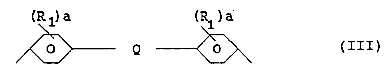
- The dihydroxy aromatic-containing compounds from which A1 is derived may also be polyol-functional chain extended compounds. Examples of such compounds include alkylene oxide extended bisphenols. Typically the alkylene oxide employed is ethylene oxide, propylene oxide, or mixtures thereof. By way of exemplification, when para, para-bisphenols are chain extended with ethylene oxide, the bivalent radical A1 may often be represented by the formulawhere each R1, each a, and Q are as discussed in respect of Formula II, and the average values of j and k are each independently in the range of from about 1 to about 4.

- The preferred aromatic-containing bis(allyl carbonate)-functional monomer is represented by the formulaand is commonly known as bisphenol A bis(allyl carbonate).

- A wide variety of compounds may be used as the polyethylenic functional monomer containing two or three ethylenically unsaturated groups. The preferred polyethylenic functional compounds containing two or three ethylenically unsaturated groups may be generally described as the acrylic acid esters and the methacrylic acid esters of aliphatic polyhydric alcohols, such as, for example, the di- and triacrylates and the di- and trimethacrylates of ethylene glycol, triethylene glycol, tetraethylene glycol, tetramethylene glycol, glycidyl, diethyleneglycol, butyleneglycol, propyleneglycol, pentanediol, hexanediol, trimethylolpropane, and tripropyleneglycol. Examples of specific suitable polyethylenic - functional monomers containing two or three ethylenically unsaturated groups include trimethylolpropanetriacrylate (TMPTA), tetraethylene glycol diacrylate (TTEGDA), tripropylene glycol diacrylate (TRPGDA), hexanedioldimethacrylate (HDDMA), and hexanedioldiacrylate (HDDA).
- A wide variety of photoinitiator compounds may be used to initiate the polymerization of the lens forming composition. The following are examples of illustrative photoinitiator compounds: 2-hydroxy-2-methyl-1-phenylpropan-1-one, 1-hydroxycyclohexyl phenyl ketone, 2,2-di-sec-butoxyacetophenone, 2,2-diethoxyacetophenone, 2,2-diethoxy-2-phenylacetophenone,2,2-dimethoxy-2-phenylacetophenone, benzoin methyl ether, benzoin isobutyl ether, benzoin, benzil, benzyl disulfide, 2,4-dihydroxybenzophenone, benzylideneacetophenone, and acetophenone. An especially preferred photoinitiator compound is 1-hydroxycyclohexyl phenyl ketone which is commercially available from Ciba-Geigy as Irgacure 184.
- As noted above, styrene having a formula ofmay optionally be present in the polymerizable composition.

- Another material which may optionally be present in the polymerizable composition is a mould release agent. When used, the mould release agent is employed in the composition in amounts sufficient to ensure that the subsequently produced lens releases easily from the mould without breaking or cracking. The mould release agent should be compatible with the polymerizable composition and should not adversely affect the physical properties of the subsequently produced lens. More particularly, the mould release agent should not adversely affect the physical properties most characteristic of the subsequently produced lens such as its rigidity, hardness, index of optical refraction, transmission of visible light and absence of colouring which affects optical clarity. The mould release agent should, therefore, be a liquid or, if a solid, be soluble in the polymerizable composition.
- Mould release agents that may be used include alkyl phosphates and stearates. Among the alkyl phosphates that may be used as a mould release agent are the mono and dialkyl phosphates (and mixtures of mono and dialkyl phosphates) which are commercially available from E.I. DuPont de Nemours & Co. under the trade names ZELEC® UN and ZELEC® NE. These alkyl phosphates are reported to have straight chain alkyl groups of from 16 to 18 carbon atoms.
- Other mould release agents that may be used include butyl stearate stearic acid, esters of stearic acid and the metal salts of stearic acid, e.g., stearic acid salts of the metals zinc, calcium, lead, magnesium, barium, cadmium, aluminum, and lithium. Other fatty acids and fatty acids salts may also be used, provided that they do not adversely affect the physical properties of the casting. Other mould release agents known to the art such as dioctylphthalate may be used.
- The composition, preferably, includes 50-150 ppm of butyl stearate, 0.5-1.5 ppm of ZELEC® UN or ZELEC® NE, or 0.3-1.5 ppm of dioctylphthalate.
- It is preferred that only one of the enumerated mould release agents and not a combination thereof is used. It is preferable to incorporate the mould release agent in the lens composition rather than spraying it on the surface of the mould faces. While coating the mould faces with a mould release agent such as butyl stearate provides effective mould release it also generates microscopic surface anomalies in the lenses. Such surface anomalies detract from the quality of the finished lens and lenses produced from such systems do not tint uniformly.
- Dyes and/or pigments are optional materials that may be present when high transmission of light is not necessary.
- The listing of optional ingredients discussed above is by no means exhaustive. These and other ingredients may be employed in their customary amounts for their customary purposes so long as they do not seriously interfere with good polymer formulating practice.
- Generally, compounds Containing acrylate groups polymerize much faster than those containing allyl groups. Thus, by including the fast polymerizing polyethylenic functional monomers in the polymerizable lens composition, yellowing is reduced because less initiator is required to complete the polymerization process.
- TTEGDA has a very long and flexible backbone between its two acrylate groups, so compositions including a high proportion of TTEGDA on the order of 70% by weight tend to be quite flexible. Preferably, other monomers that provide more stiffness are included in the composition and the proportion of TTEGDA is reduced. Stiffness is provided, preferably, by incorporating monomers that have shorter and stiffer backbones than TTEGDA such as HDDMA or TRPGDA. Stiffness may be provided, according to some embodiments of the present invention, by incorporating polyethylenic functional monomers containing three acrylate groups such as trimethylolpropane triacrylate (TMPTA).
- To reduce the formation of cracks in the lenses, it is preferable to reduce the rate of polymerization and reduce the maximum temperature of the lens composition during the curing process. Generally, if there is a large enough temperature difference between the hardening lens and its surroundings, the lens will crack.
- The rate of polymerization and the maximum temperature are reduced, preferably, by optimizing three factors: monomer composition, initiator concentration and incident light intensity. The rate of polymerization, preferably, is sufficiently reduced by decreasing the concentration of photoinitiator and by decreasing the intensity of the incident light. TTEGDA and TRPGDA are very fast reacting monomers although TRPGDA reacts slightly slower than TTEGDA. The higher the proportion of TTEGDA, the faster the reaction, the higher the shrinkage of the lens, the greater the heating effect and the more susceptible the lens is to cracking or premature release from the mould. Slower reacting monomers, preferably, are mixed with these very reactive monomers to bring the rate of polymerization under control and reduce the rate of heat generation. A balance is achieved between slower monomers and very reactive monomers to avoid lens cracking while at the same time providing a rapid enough rate of polymerization to minimize the concentration of initiator and diminish yellowing.
- Conventional high pressure mercury arc lamps used to cure plastic lenses were found to have a detrimental effect on the quality of the produced lens. Aside from being cumbersome, expensive and dangerous, these high intensity lamps contributed to the rapid rise in temperature as well as the rate of polymerization. It was found preferable for the conventional high pressure mercury arc lamps to be replaced by bulbs that generate approximately 5-10 mW/sqcm of ultraviolet light having wavelengths between 300 and 400 nm, which light is very uniformly distributed without any sharp discontinuities throughout the reaction process. Such bulbs are commercially available from Sylvania under the trade designation Sylvania Fluorescent (F158T/2052) or Sylvania Fluorescent (F258T8/350BL/18'') GTE. As noted above, ultraviolet light having wavelengths between 300 and 400 nm is preferred because most of the preferred photoinitiators of the composition of the present invention absorb most efficiently at this wavelength and the moulds used according to the present invention allow a maximum transmission at this wavelength.
- It is preferred that the light source generates light having substantially uniform intensity. It is also preferred that the incident light have no sharp discontinuities to reduce the possibility of lens cracking. Moreover, it is preferred that there be no sharp intensity gradients of ultraviolet radiation either horizontally or vertically through the lens composition during the curing process because sharp intensity gradients through the lens lead to defects in the finished lens. It is preferred that several light sources configured as a bank of lights be utilized to generate the uniform light. It is also preferred that a suitable light diffuser be disposed between the light source and the reaction solution to maximize the uniformity of light distribution. Suitable light diffusers include frosted glass moulds or one or more sheets of tracing paper.
- It is preferred that the maximum temperature of the lens forming composition during the cure thereof be less than 50°C. to reduce the tendency of the lens to fracture. In addition to the above-noted techniques for reducing the temperature, filters disposed between the light source and the reaction cell, as well as cooling fans to carry heat away from the reaction cell may be used to reduce the heating effects. Finally, when curing thick positive lenses, intermittent rather than continuous radiation is effective to reduce the heating effect.
- Commercially available preparations having utility in the present invention which include bisphenol A bis(allyl carbonate) as their major component are available from PPG Inc. under the trade name HIRI II.
- In one of its commercially available forms, HIRI II includes approximately 91% bisphenol A bis(allyl carbonate), 7% DEG-BAC and 2% antiyellowing additives. The antiyellowing additives are UV blockers which absorb strongly at 326 nm. in the region where the photoinitiators absorb. The antiyellowing additives, preferably, are removed before the material is used in a photochemical polymerization reaction. This component, preferably, is removed by passing the HIRI through a column of alumina (basic). Because of its high viscosity, the HIRI II material is preferably mixed with the less viscous TTEGDA before passing it through an alumina column.
- When used in the composition of the present invention, it is preferred that the bisphenol A bis(allyl carbonate) monomer be obtained without DEG-BAC or the antiyellowing additives. Lenses made from this product sometimes have a very slight, barely detectable, degree of yellowing. A small amount of a blue dye consisting of 9, 10-anthracenedione, 1-hydroxy-4-[(4-methylphenyl)amino] available as Thermoplast Blue 684 from BASF Wyandotte Corp. is preferably added to the composition to counteract the yellowing.
- Bisphenol A bis(allyl carbonate) has a much higher refractive index than DEG-BAC and thus allows the production of thinner lenses when compared to DEG-BAC lenses. If more than 30% by weight of bisphenol A-bis(allyl carbonate is included in the most preferred composition, however, compatibility or solubility problems between the various monomers develop resulting in a cloudy, foggy or milky lens.
- TTEGDA is a diacrylate monomer that, preferably, is included in the composition because it is a fast polymerizing monomer that reduces yellowing and yields a very clear product. If too much TTEGDA is included in the most preferred composition, i.e. greater than about 18% by weight, however the finished lens will be prone to cracking and will be too flexible as this material softens at temperatures above 40°C. If TTEGDA is excluded altogether, the finished lens tends to be brittle.
- HDDMA is a dimethacrylate monomer that has a very stiff backbone between the two methacrylate groups. HDDMA, preferably, is included in the composition because it yields a stiffer polymer and increases the hardness and strength of the finished lens. This material is also quite compatible with the bisphenol A bis(allyl carbonate) monomer. HDDMA contributes to high temperature stiffness, polymer clarity and speed of polymerization.
- TRPGDA is a diacrylate monomer that, preferably, is included in the composition because it provides good strength and hardness without adding brittleness to the finished lens. This material is also stiffer than TTEGDA.
- TMPTA is a triacrylate monomer that, preferably, is included in the composition because it provides much more crosslinking in the finished lens than the difunctional monomers. TMPTA has a shorter backbone than TTEGDA and increases the high temperature stiffness and hardness of the finished lens. Moreover, this material contributes to the prevention of patterns in the finished lens. TMPTA also contributes to high shrinkage during polymerization. The inclusion of too much of this material in the most preferred composition, i.e. in excess of 20% by weight makes the finished lens too brittle so that it breaks under the drop-ball test.
- Styrene is a high refractive index comonomer that, preferably, is included in the composition because it acts as a coordinating material. If styrene is not included, incompatibility problems may arise which result in a cloudy lens. Styrene appears to act as a bridging agent which allows the bisphenol A bis(allyl carbonate) to polymerize with the other monomers. The inclusion of too much styrene in the most preferred composition, i.e. greater than about 3% by weight will result in a loss of strength in the finished lens, because styrene is a single vinyl group monomer.
- Certain of the monomers that are preferably utilized in the composition of the present invention, such as TTEGDA, TRPGDA and TMPTA, include impurities and have a yellow colour in certain of their commercially available forms. The yellow colour of these monomers is preferably removed by passing them through a column of alumina (basic) which includes aluminum oxide powder - basic. After passage through the alumina column, the monomers absorb almost no ultraviolet light. Also after passage through the alumina column differences between monomers obtained from different sources are substantially eliminated. It is preferred, however, that the monomers be obtained from a source which provides the monomers with the least amount of impurities contained therein. The styrene, preferably, is also passed through a column of alumina (basic) before use. The composition preferably is filtered prior to polymerization thereof to remove suspended particles.
- As noted above, TTEGDA and TRPGDA are highly reactive monomers, with TTEGDA being slightly more active than TRPGDA. Slower reacting monomers such as TMPTA and HDDMA, preferably, are mixed with the very reactive monomers to bring the rate of polymerization under control and reduce the rate of heat generation. The degree of yellowing, preferably, is diminished by increasing the proportion of TTEGDA or TRPGDA to increase the reaction rate and reduce the concentration of initiator. Lens hardness depends on a balance between initiator concentration, exposure time, and formulation. The ultraviolet light cured lenses demonstrate excellent organic solvent resistance to acetone, methylethyl ketone, and alcohols. The lenses produced as described, preferably, are cured in approximately 15 to 30 minutes.
- A reaction cell was also developed. The reaction cell can be used with a proper mould arrangement to prepare positive or negative lenses that are free from defects.
- A first embodiment of the reaction cell is shown in Figure 6. As shown in Figure 6, the reaction cell generally indicated by 100 includes opposed
glass mould parts 102 and agasket device 104 which together form alens moulding chamber 106. The polymerizable lens forming composition is disposed within thelens moulding chamber 106. Theglass mould parts 102,gasket device 104 andlens moulding chamber 106 are sandwiched between opposedradiation lenses 108. In this manner, incident light entering thereaction cell 100 must first pass through one of theradiation lenses 108. - Figure 7 illustrates a second embodiment of the reaction cell which includes components identical to some components of the previous embodiment which components are given the same reference numerals. As shown in Fig. 7, the
reaction cell 100 includes the opposedglass mould parts 102 and agasket device 104 which together form thelens moulding chamber 106. The polymerizable lens forming composition is disposed within thelens moulding chamber 106. Theglass mould parts 102,gasket device 104 andlens moulding chamber 106 are sandwiched between opposed powerless glass moulds 108 and thermally insulated by a pair ofgaskets 110. The powerless glass moulds 108 andgaskets 110 together form a thermally insulated radiation chamber. Preferably, the powerless glass moulds 108 have a larger diameter than thelens moulding chamber 106 so that incident light is allowed to reach the full extent of thechamber 106. Preferably, tracing paper (not shown) is inserted between the powerless glass moulds 108 and theglass mould parts 102. In an alternate preferred embodiment, instead of inserting tracing paper between the powerless glass moulds 108 and theglass mould parts 102, the powerless glass moulds 108 are replaced by frosted glass moulds. - The
reaction cell assembly 100 is preferably constructed to minimize heat exchange between the reaction cell and its surroundings. Heat exchange with the surroundings has been found to cause cracking and other problems. - In one embodiment, the
gasket 104 is constructed of vinyl material, has good lip finish and maintains sufficient flexibility at conditions around to T(max) of 45°C. In a preferred embodiment thegasket 104 is constructed of silicon material. In another preferred embodiment thegasket 104 is comprised of copolymers of ethylene and vinyl acetate which are commercially available from E.I. DuPont de Nemours & Co. under the trade name ELVAX®. Preferred ELVAX® resins are ELVAX® 350 having a melt index of 17.3-20.9 dg/min and a vinyl acetate content of 24.3-25.7 wt. %, ELVAX® 250 having a melt index of 22.0-28.0 dg/min and a vinyl acetate content of 27.2-28.8 wt. %, ELVAX® 240 having a melt index of 38.0-48.0 dg/min and a vinyl acetate content of 27.2-28.8 wt. %, and ELVAX® 150 having a melt index of 38.0-48.0 dg/min and a vinyl acetate content of 32.0-34.0 wt. %. The gaskets are prepared by conventional injection moulding techniques which are well-known by those of ordinary skill in the art. - Premature release often occurs when the moulds are held too rigidly by the gasket. There must be sufficient flexibility in the gaskets to permit the moulds to follow the lens as it shrinks. Insufficient sealing, unsuitable gasket material and/or a small residual amount of uncured material have been found to contribute to premature release failures.
- For best results, both sides of the mould surfaces should be as smooth as possible, with no scratches. They should also have a smooth edge finish. Scratches in the moulds have been found to be more important than just producing the same defect in the finished lens. During the reaction free radicals are generated and these free radicals may be sensitive to surface conditions, particularly if no mould release agent is used. Scratches on the surface may initiate cracking and aberrations. Scratches may cause more or less adhesion and premature release often appears to begin at a scratch.
- Mould markings cause differential light intensity conditions under the marking, even when the mark is on the outside surface of the mould. The fully exposed region of the lens will be harder, and the sample may have stresses because of this. The portion of the lens under the mark will be weaker at the end of the curing period. This effect has been observed and can cause premature release or induce cracking.
- The invention will now be described in more detail with reference to the following examples.
- The photo-initiating efficiency of various commercially available initiator compounds in the polymerization of diethylene glycol bis(allyl)carbonate (DEG-BAC) was investigated at a constant light intensity of 17mW/cm2, and initiator concentration of 3%(w/v). The rate of polymerization was monitored by IR-spectroscopy using the absorption band of the stretching vibration of the olefinic double bond at 1650cm-1. The results showed that 2-hydroxy-2-methyl-1-phenylpropan-1-one and 1-hydroxycyclohexyl phenyl ketone have the highest efficiency as initiators for the polymerization of DEG-BAC. In contrast, benzoin and benzoin ethers produced much lower rates of polymerization and are therefore poor initiators for DEG-BAC.
- A Hanovia medium pressure mercury lamp, containing a small amount of iron iodide to improve the spectral output in the UV-region around 350 nm, was used as a UV-light source. The lamp was housed in an air cooled housing equipped with an elliptical reflector. The lamp was operated with a special stabilizer ballast to supply constant power at three different intensities of 49, 78 and 118 watt/cm (125, 200, and 300 Watts/inch). A 6.3 mm (1/4 inch) filter of PYREX glass was placed in the path of the beam to absorb short wavelength UV-light. PYREX is a Registered Trade Mark. The total incident light intensity was measured by a digital radiometer equipped with a 1 cm2 diffuse-sensor window. This radiometer operates in the spectral range of 320 to 380 nm with a full range reading from zero to 200 mW/cm2.
- All IR-spectroscopy was performed on a Nicolet 7199 Fourier Transform spectrophotometer equipped with a triglycine sulfate detector.
- UV-spectra of the initiator/monomer solutions were recorded on a Shimadzu UV-160, a microcomputer controlled double beam UV-Vis spectrophotometer.
- A solution of 3% initiator in monomer was made up on a weight/volume basis. After the initiator was dissolved in the monomer, the solution was transferred into a test tube and flushed with nitrogen for 15 minutes to sweep out dissolved oxygen. A few drops of the solution were sandwiched between two sodium chloride disks which were separated by a 0.05mm stainless steel spacer, and then secured in a demountable cell mount. After the cell was assembled, an IR-spectrum was taken. The sample cell was then irradiated for the desired time, removed, and immediately analyzed on the IR-spectrophotometer. This exposure-IR-spectrum cycle was repeated seven or eight times for each sample. Duplicate experiments with different initiators were carried out following the same procedure. The peak area of the IR-bands was calculated using the SETUP computer program which was run from a DEXTER/2 system.
- Fig. 4 shows an IR-absorption spectra of DEG-BAC before and after irradiation in the presence of 2-hydroxy-2-methyl-1-phenylpropan-1-one, which is commercially available from EM Chemicals under the trademark Darocur 1173. The point of interest is the large decrease of absorption at 1650 cm-1 (band A), which is the C=C stretching vibration in the allyl portions of the DEG-BAC. As shown in Fig. 5 this absorption band is an excellent index of the extent of polymerization of DEG-BAC. Other changes in the IR absorption spectra occur, but as the absorption band at 1650 cm-1 is due to a fundamental vibration mode, it is the most reliable criteria of the unsaturation content.
- The percent residual unsaturation of DEG-BAC was calculated using the following equation:
- Although the demountable cell was used with a fixed spacer, the apparent thickness of the sample was observed to change due to the increase in density as the polymerization proceeds. A band at 1581 cm-1 (band B), which did not change appreciably during polymerization, was used as an internal standard. To obtain the correct % unsaturation a correction factor of Bo/Bt was applied to equation 1.
Data for the Polymerization of DEG-BAC with 3% 2-Hydroxy-2-methyl-1-phenylpropan-1-one and light intensity of 17 mW/cm2 Exposure (second) Absorption area of band A Absorption area of band B Unsaturation (%) 0 5.1259 1.5541 100.00 60 4.6551 1.5535 90.85 90 4.3616 1.5414 85.79 120 4.0011 1.5118 80.24 180 3.5442 1.4889 72.17 300 2.8985 1.4730 59.66 480 2.3365 1.4513 48.81 - As a further check on validity of this technique or equation 2, two additional analytical methods were used; refractive index and iodometry. The refractive index method was based on data published by Starkweather and Eirich, Ind. Eng. Chem., 47: 2452 (1955) from which the conversion factor was deduced. The iodine value method was that described in ASTM D1541-60. The results are shown in Table II below.
Percent Residual Unsaturation of the Irradiated DEG-BAC by Three Different Methods. Method: IR Refractive Index Iodometry 92.5 92.2 -- 91.3 93.0 -- 89.5 89.5 -- 88.8 89.5 -- 83.3 -- 87.0 73.3 -- 76.1 57.1 -- 60.4 29.0 -- 30.0 Comparison of these two methods with the IR method using equation 2 shows reasonable agreement. - The initial rates of polymerization after sequential UV-irradiation were taken from the slopes of the initial part of the % unsaturation-time curves. Table III summarizes the results obtained for the polymerization of DEG-BAC with various initiators at room temperature.
Initial Rates (Rp) of Photopolymerization of DEG-BAC with 3% Initiator and Light Intensity of 17 mW/cm2 in the 320-380 nm Region. Initiator λmax (logξ) Rp x 104M/sec 2-Hydroxy-2-methyl-1-phenylpropan-1-one 313 (1.87) 68.8 1-Hydroxycyclohexyl phenyl ketone 328 (1.94) 60.9 2,2-Di-sec-butoxyacetophenone 335 (1.94) 47.9 2,2-Diethoxyacetophenone 334 (1.87) 40.7 2,2-Diethoxy-2-phenyl-acetophenone 343 (2.38) 39.5 2,2-Dimethoxy-2-phenyl-acetophenone 318 (2.34) 37.3 Benzoin methyl ether 339 (2.34) 18.5 Benzoin isobutyl ether 340 (2.31) 11.3 Benzoin 312 (2.58) 9.65 Benzil 382 (1.86) 5.96 Benzyl disulfide 242 (3.54) 4.05 2,4-Dihydroxybenzophenone 324 (3.99) 4.00 Benzylideneacetophenone 308 (4.08) 3.73 Acetophenone 315 (1.72) 0.81 Conditions for all runs were 3% initiator(w/v) and 17 mW/cm2 effective intensity in the 320-380 nm region. The results show that 2-hydroxy-2-methyl-1-phenylpropan-1-one, which is commercially available from EM Chemicals under the trademark Darocur 1173 and 1-hydroxycyclohexyl- phenyl ketone, which is commercially available from Ciba-Geigy under the trademark Irgacure 184 are the best photoinitiators for DEG-BAC in the group studied. Benzoin ethers, however, which showed high efficiency as initiators for vinyl polymerization, are much less effective in the photopolymerization of DEG-BAC. - The objective of this example was to develop a composition including DEG-BAC and a procedure for the production of moulded eyeglass lenses by ultraviolet photoinitiation.
- It was found to be difficult to prepare an acceptable product by using DEG-BAC and photoinitiator alone in conjunction with the present radiation system. It was determined that the addition of other monomers was essential to obtain the most desirable combination of optical and mechanical properties in the finished lens. The additional monomers were selected from monofunctional and multifunctional acrylates or methacrylates.
- The final composition of the raw material was miscible, clear, and dust free. In addition, the ultraviolet transmission of the components except for the photoinitiator were at a maximum in the desired range.
- The preferred composition is shown in Table IV.
Materials Supplier Weight(%) range 2-hydroxy-2-methyl-1-phenyl-propan-1-one (Darocur 1173) EM Chemicals 0.7-1.3 1-hydroxy cyclohexyl-phenyl ketone (Irgacure 184) Ciba-Geigy 1.2-1.8 Trimethylol propanetriacrylate (TMPTA) Aldrich, Interez 2.5-3.0 Tetrahydrofurfuryl-methacrylate (TFFMA) Sartomer (Arco) 3.0-2.5 Tetrahydrofurfuryl-acrylate (TFFA) Sartomer 12.0-25 Diethylene glycol bis(allyl)-carbonate (DEG-BAC) PPG Inc. 80.3-72.3 - The reaction cell included two glass windows shaped to produce the lens and a flexible silicon or vinyl gasket. The glass moulds reproduced the lens surfaces. The inside curvature of the moulds together with the gasket thickness controlled the lens shape and power. To produce good quality lenses it was important that the glass moulds had no surface scratches or other defects.
- The spectral range of interest for ultraviolet radiation curing is 320-400 nm where the most efficient photoinitiators absorb and moulds of crown glass allow maximum transmission.
- Of the high intensity sources of light available, iron added-mercury arc lamps offer a high output within this preferred range and thus were used in this system. Shorter wavelengths below 320 nm. were blocked by a 6.3mm (1/4 inch) PYREX glass filter placed at 15.2-20.3 cms (6-8 inches) from the lamp and 12.7-17.8 cms (5-7 inches) from the reaction cell. This blockage of the short wavelengths was found to be important. If the full intensity of the ultraviolet light source was allowed to strike the glass mould it broke due to the strong absorption of the shorter wavelengths by the glass. Even small amounts of radiation at this wavelength caused heating problems that were severe.
- Additional advantages offered by the PYREX glass filter included a significant reduction in unwanted IR heat problems normally produced by the lamp. Heat was continuously removed, without disturbing the lamp stability, by blowing air past the filter and the reaction cell. The ultraviolet rays emanating from the lamp were passed through two or three sheets of closely spaced tracing paper at 7.6 cms (3 inches) from the reaction cell or 5 to 10 cms (2-4 inches) from the PYREX glass filter. The tracing paper increases the uniformity of light distribution with a further reduction in the heating problems.
- The light intensity in the 320-400 nm. range, under the above conditions, was reduced from 27 mW/sqcm. (in the absence of the PYREX glass filter and the tracing paper) to about 6-10 mW/sqcm. with an excellent performance compared with an unmodified radiation system even at comparable light intensity.
- Alternatively, it was determined that the high-pressure mercury arc lamps could be replaced by fluorescent tubes without a loss in performance. Sylvania and Philips both produce acceptable fluorescent tubes that generate almost all of their output in the desirable range (320 to 390 nm.). A bank of these lamps was capable of producing at least 8 mW/sqcm. and were effective in this system. These fluorescent tubes provide many advantages over the high-pressure mercury arc lamps as they are inexpensive, compact, and require much less power.
- Two illumination sources were used to provide ultraviolet light exposure simultaneously to both sides of the reaction cell. The critical point in the irradiation was found to occur shortly after the gelation point when the rate of polymerization increased drastically and the mobility of the reacting monomer units decreased which resulted in a rapid increase in temperature, especially in thicker samples. At this point cracking of the sample occurred if the temperature difference became too great. This critical stage was controlled by monitoring the temperature at the mould surface and keeping the difference in temperature between the mould surface and the surroundings to less that 20°C. At room temperature this meant keeping the temperature at the mould surface below 50°C (120°F). An alternative was to reduce the intensity of the ultraviolet light radiation, but this resulted in a longer irradiation time. Another possibility was to reduce the concentration of photoinitiator, which also increased the irradiation time and caused other problems.
- The reaction cell was placed where at least 20% of the incident light passed through the cell, to ensure that regions farthest from the lamps received adequate radiation. Using a value of 6 mW/sqcm of incident light it was required that there be 1.2 mW/sqcm passing through the cell.
- Two lamps were used to provide sufficient radiation energy throughout the lens forming material so that any deficiency in energy on one side was compensated for by the lamp on the other side. It was found to be very difficult to obtain uniform irradiation with only one lamp.
- The monomer mixture contained co-monomers that improved the most needed properties. TMPTA was useful in reducing the effect of unequal radiation over the body of the lens. Without TMPTA, visible distortions occurred. TFFA was added to add flexibility to the mixture to prevent cracking of the lens. Between 12 and 25% by weight of TFFA was effective. Above 25% caused too much flexibility and less than 12% failed to prevent cracking. An added bonus was that the addition of TFFA also improved the mould release. A drawback was that TFFA slightly increased the yellowing of the lens.
- The procedure for producing lenses was as follows:
- 1. The necessary amount of initiator was dissolved in TFFA using adequate agitation.
- 2. The necessary amount of DEG-BAC and other ingredients was poured into the photoinitiator-TFFA solution (with adequate agitation) to obtain a clear fluid free of undissolved particles. In some cases, it was helpful to warm the mixture to about 10°C above room temperature to ensure that the mixture attained a good homogeneous state.
- 3. Enough lens solution was placed in the cell container which was composed of the concave part of the cell window supported by the desired flexible gasket. The other window was carefully arranged to allow air to escape freely using a micro spatula inserted between the glass mould and the gasket. Once the cell was filled, the spatula was removed and the gasket returned to a sealing condition.
- 4. The windows were checked and any spillage was removed by vacuum suction.
- 5. The reaction cell was placed in position between the two radiation sources and the reaction was begun using both sources. The surface temperature was not allowed to exceed 50°C in the first 5-10 minutes.
- 6. At the completion of the curing process (20-60 min. depending on thickness of lens, curvature of lens, the reaction temperature and program of radiation) the reaction cell was allowed to cool to room temperature.
- 7. The gasket was removed and the windows were carefully removed using a razor or knife inserted between the cured lens and the glass window with a gentle mechanical shock.
-
- Mould defects at the edges interfere with the sealing conditions and frequently induce premature release.
- In each of the following examples, the monomer bisphenol A bis(allyl carbonate) was obtained from PPG Industries , Inc.; the tetraethylene glycol diacrylate (TTEGDA) monomer was obtained from Interez, the 1,6 hexanedioldimethacrylate (HDDMA) monomer was obtained from Rohm Tech, Inc. or Sartomer, the tripropylene glycol diacrylate (TRPGDA) and trimethylolpropanetriacrylate (TMPTA) monomers were obtained from Interez or Sartomer, the styrene monomer was obtained from Fisher and the 1-hydroxycyclohexyl phenyl ketone photosensitizer was obtained from Ciba-Geigy under the trademark Irgacure 184.
- The objective of this Example was to produce optical lenses incorporating bisphenol A bis (allyl carbonate) that were not brittle, had desirable colour and clarity, and did not have any patterns, defects or aberrations.
- The results of various representative sample formulations are indicated below. In each trial the following conditions were observed:
- 1. All liquid materials were treated with alumina powder (basic) before use.
- 2. Sylvania Fluorescent (F158T/2052) lamps which generate an intensity of 5.0 to 6.6 mW/sqcm of UV light were used as a light source. UV light reaching the mould surface, however, was one the order of 1.5 mW/sqcm and the samples were irradiated for approximately 20 minutes.
- 3. The moulds had a diameter of 75 nm.
- 4. The bisphenol A bis(allyl carbonate) monomer was obtained from PPG Industries, Inc., in a formulation that included 91% by weight bisphenol A bis(allyl carbonate), 7% by weight DEG-BAC and 2% by weight antiyellowing additives. The antiyellowing additives, which are UV absorbers, were removed prior to formulating the compositions.
-
- A plastic lens composition including a monomer mixture consisting of:
- 22.12 parts by weight of bisphenol A bis(allyl carbonate), (together with 1.69 parts by weight of DEG-BAC), 15.8 parts by weight of TTEGDA, 15.0 parts by weight of TRPGDA 19.6 parts by weight of TMPTA, 22.3 parts by weight of HDDMA, 3.50 parts by weight of styrene; a photosensitizer consisting of 0.05 parts by weight of 1-hydroxycyclohexyl phenyl ketone; and a mould release agent consisting of 76 ppm of butyl stearate were placed in a reaction chamber disposed between opposed 550 and 775 glass moulds configured to generate a positive correction lens. The moulds were separated by a distance of 1.8 mm by a vinyl type gasket. The radiation cell was as described above with reference to Fig. 6 and the radiation lenses were negative power lenses.
-
- The composition was irradiated for a period of 17 minutes and exhibited a smooth and slow rate of temperature increase.
- The lens was an overall good product exhibiting a favourable appearance in terms of colour and clarity and having a flexibility resistance that was better than conventional DEG-BAC lenses.
- A plastic lens composition including a monomer mixture consisting of:
- 23.70 parts by weight of bisphenol A bis(allyl carbonate), (together with 1.81 parts by weight of DEG-BAC), 15.9 parts by weight of TTEGDA, 15.3 parts by weight of TRPGDA, 16.2 parts by weight of TMPTA, 23.4 parts by weight of HDDMA, 3.60 parts by weight of styrene; a photosensitizer consisting of 0.051 parts by weight of 1-hydroxycyclohexyl phenyl ketone; and a mould release agent consisting of 114 ppm of butyl stearate were placed in a reaction chamber disposed between opposed glass moulds configured to generate a positive (2.7D) correction lens. The glass moulds were separated by a vinyl type gasket. The glass moulds were washed and treated with methylethyl ketone prior to the reaction. The radiation cell was as described above with reference to Fig. 6 and the radiation lenses were negative power lenses.
-
- The composition was irradiated for a period of 18 minutes and exhibited a smooth reaction that was not too fast and not too slow. The lens did not crack and did not release prematurely. The lens had a flexibility resistance that was better than conventional DEG-BAC lenses. The lens, however, was brittle near its edges which is believed to be caused by slight interference with the incident light caused by the lens moulding apparatus.
- A plastic lens composition including a monomer mixture consisting of:
- 26.10 parts by weight of bisphenol A bis(allyl carbonate) (together with 2.00 parts by weight of DEG-BAC), 14.0 parts by weight of TTEGDA, 16.8 parts by weight of TRPGDA, 14.3 parts by weight of TMPTA, 24.1 parts by weight of HDDMA, 2.60 parts by weight of styrene; a photosensitizer consisting of 0.048 parts by weight of 1-hydroxycyclohexyl phenyl ketone; were placed in a reaction chamber disposed between opposed 660 and 500 glass moulds configured to generate a negative correction lens. The moulds were separated a distance of 4.8 mm by a gasket. The radiation cell was as described above with reference to Figure 6. The moulds were sprayed with butyl stearate as a mould release agent prior to the curing process.
-
- The composition was irradiated for a period of 20 minutes. The finished lens exhibited no haziness and good hardness but was brittle at its edges. The butyl stearate sprayed on the mould surface led to surface anomalies in the finished lens.
- The objective of this Example was to produce optical lenses incorporating bisphenol A bis(allyl carbonate) that were not brittle, had desirable colour and clarity, and did not have any patterns, defects or aberrations.
- In each trial of this Example, Sylvania Fluorescent (F158T/2052) lamps which generate an intensity of 5.0 to 6.6 mW/sqcm. of UV light were used as a light source.
- The basic ingredients of the formulations according to Example 4 included TTEGDA, TRPGDA, TMPTA, bisphenol A bis(allyl carbonate), styrene and 1-hydroxycyclohexyl phenyl ketone which are commercially available from the sources set forth above.
- Zelec® UN was tested as a mould release agent to supplement butyl stearate.
- Often, the monomers were passed through beds of alumina (basic) to remove impurities. This was especially true for the monomer TRPGDA.
- The results of various representative sample formulations are indicated below.
- Sample formulation 4 was irradiated in a reaction cell as described above with reference to Figure 6.
- Each of sample formulations 5-7 and comparative sample formulations 8-9 was irradiated in a reaction cell as described above with reference to Figure 7.
- As shown in Figure 7, the
lens forming chamber 106 is thermally insulated on the sides bygaskets 110. According to this example, thechamber 106 was thermally insulated by twolarge gaskets 110 having the following dimensions: 92 mm OD, 85 mm ID and 75 mm lip diameter, and on top and bottom by two powerless glass moulds 108 having a 76 mm diameter which fit into thelarge gaskets 110. Three sheets of tracing paper were inserted between the powerless glass moulds 108 and the glass moulds 102 of thelens forming chamber 106. Heat exchange between the reaction cell and its surroundings was reduced greatly with this arrangement. - Frosted glass in place of the glass moulds 108 was tried and worked as well as clear glass moulds 108 plus tracing paper. In any case, good sealing was very important to produce high quality lenses. -
- Gasket material and lip finish were also very important. Most of the trials were carried out using vinyl gaskets that had been used many times so that the quality of the lip had deteriorated making sealing difficult.
- Imperfect sealing and gasket material, plus a small residual amount of uncured material contributed to premature release.
- When the lens cavity was not completely sealed, a small amount of air leaked in and prevented the polymerization of the monomer mixture that it reached resulting in some uncured residual liquid remaining at the gasket lip.
- A plastic lens composition including a monomer mixture consisting of:
- 24.13 parts by weight of bisphenol A bis(allyl carbonate) (together with 1.84 parts by weight of DEG-BAC), 16.05 parts by weight of TTEGDA, 15.64 parts by weight of TRPGDA, 16.59 parts by weight of TMPTA, 23.87 parts by weight of HDDMA, 1.48 parts by weight of styrene; a photosensitizer consisting of 0.02 parts by weight of 1-hydroxycyclohexyl phenyl ketone were placed in a reaction chamber disposed between opposed glass moulds configured to generate a bifocal correction lens. The glass moulds were separated by silicon gaskets to produce a lens that was 2mm thick at the edge and 7.7mm thick in the centre. The lens composition was irradiated for a total of 36 minutes. After 20 minutes of irradiation mould release occurred at the bifocal. The ultraviolet light passing through the cell had an intensity of 1.1 mw/sqcm. Under these conditions the t(max) reached 48°C after 16 minutes of irradiation and fell to 47°C after 20 minutes of irradiation. After the radiation there was found some residual liquid around the gasket lip. The produced lens had excellent colour, no patterns and good hardness. The edge of the lens was not perfect but the lens was still an overall acceptable product.
-
- A plastic lens composition including a monomer mixture consisting of:
- 24.15 parts by weight of bisphenol A bis(allyl carbonate) (together with 1.85 parts by weight of DEG-BAC), 16.0 parts by weight of TTEGDA, 15.6 parts by weight of TRPGDA, 16.6 parts by weight of TMPTA, 23.9 parts by weight of HDDMA, 1.8 parts by weight of styrene; and a photosensitizer consisting of 0.02 parts by weight of 1-hydroxycyclohexyl phenyl ketone were placed in a reaction chamber disposed between opposed 550 and 775 glass moulds configured to generate a positive 3D correction lens. The glass moulds were separated by a distance of 1.8 mm by vinyl gaskets. The lens composition was irradiated for 40 minutes and the finished lens showed no patterns, had good hardness, and good colour and clarity.
-
- A plastic lens composition including a monomer mixture consisting of:
- 24.15 parts by weight of bisphenol A bis(allyl carbonate) (together with 1.85 parts by weight of DEG-BAC), 16.0 parts by weight of TTEGDA, 15.6 parts by weight of TRPGDA, 16.6 parts by weight of TMPTA, 23.9 parts by weight of HDDMA, 1.8 parts by weight of styrene; and a photosensitizer consisting of 0.02 parts by weight of 1-hydroxycyclohexyl phenyl ketone were placed in a reaction chamber disposed between opposed glass moulds configured to generate a positive 5D or 6.5D correction lens. In these trials the glass moulds were separated by an ethylene vinyl acetate gasket. The lens compositions were irradiated for 46 minutes and the finished lenses showed no patterns, had good hardness and good colour and clarity.
-
- A plastic lens composition including a monomer mixture consisting of:
- 24.15 parts by weight of bisphenol A bis(allyl-carbonate) (together with 1.85 parts by weight of DEG-BAC), 16.0 parts by weight of TTEGDA, 15.6 parts by weight of TRPGDA, 16.6 parts by weight of TMPTA, 23.9 parts by weight of HDDMA, 1.8 parts by weight of styrene; and a photosensitizer consisting of 0.02 parts by weight of 1-hydroxycyclohexyl phenyl ketone were placed in a reaction chamber disposed between opposed glass moulds configured to generate negative correction lenses. The moulds were configured to generate a -1 lens or a -4 lens. The lens composition was irradiated for 40 minutes. The -1 lenses were successfully completed while the -4 lenses prematurely released.
-
- The objective of this Example was to produce optical lenses, incorporating bisphenol A bis(allyl carbonate) that were not brittle, had desirable colour and clarity, and did not have any patterns, defects or aberrations.
- In each trial of this Example bisphenol A bis(allyl carbonate) was used. It was determined that any yellowing problems in lenses made from bisphenol A bis(allyl carbonate) could be counteracted and overcome by including a very small amount on the order of one drop or from about 0.2 to 0.4 ppm of styrene containing a blue dye including 9.10-anthracenedione, 1-hydroxy-4-[(4-methylphenyl) amino] (available as Thermoplast Blue 684 from BASF Wyandotte Corp.)
- In each trial of this Example, Sylvania Fluorescent (F158T/2052) lamps which generate an intensity of 5.0 to 6.6 mW/sqcm of UV light were used as a light source.
- A plastic lens composition including a monomer mixture consisting of:
- 24.50 parts by weight of bisphenol A bis(allyl carbonate), 16.2 parts by weight of TTEGDA, 16.7 parts by weight of TRPGDA, 16.7 parts by weight of TMPTA, 22.7 parts by weight of HDDMA, 3.0 parts by weight of styrene; a photosensitizer consisting of 0.023 parts by weight of 1-hydroxycyclohexyl phenyl ketone; and mould release agent consisting of 0.7 ppm of Zelec® UN were placed in a reaction chamber disposed between opposed 660 and 520 glass moulds configured to generate a negative correction lens. The moulds were separated a distance of 4.8 mm by a gasket. The lens composition was irradiated for approximately 20 minutes.
-
- The intensity of ultraviolet light entering the mould was 2.2 mW/sqcm from above and 2.5 mW/sqcm from below.
- Frosted glass was used in place of the insulated powerless glass moulds.
- The finished lens had good colour and clarity, no patterns and good hardness without brittleness.
- A plastic lens composition including a monomer mixture consisting of:
- 24.50 parts by weight of bisphenol A bis(allyl carbonate), 16.2 parts by weight of TTEGDA, 16.7 parts by weight of TRPGDA, 16.7 parts by weight of TMPTA, 22.7 parts by weight of HDDMA, 3.0 parts by weight of styrene; a photosensitizer consisting of 0.023 parts by weight of 1-hydroxycyclohexyl phenyl ketone; and a mould release agent consisting of 0.7 ppm of Zelec® UN were placed in a reaction chamber disposed between opposed 550 and 775 glass moulds configured to generate a positive correction lens. The moulds were separated a distance of 1.8 mm by a gasket. The lens composition was irradiated for approximately 20 minutes.
-
- The intensity of ultraviolet light entering the mould was 2.2 mW/sqcm from above and 2.5 mW/sqcm from below.
- Instead of frosted glass, clear radiation lenses were used and tracing paper was used over the lamps with 2 sheets at top and 1 sheet at bottom.
- The finished lens had more favourable characteristics than the lens of Formulation 10A.
- A plastic lens composition including a monomer mixture consisting of:
- 25.60 parts by weight of bisphenol A bis(allyl carbonate), 15.1 parts by weight of TTEGDA, 16.1 parts by weight of TRPGDA, 16.5 parts by weight of TMPTA, 24.1 parts by weight of HDDMA, 2.5 parts by weight of styrene; a photosensitizer consisting of 0.0195 parts by weight of 1-hydroxycyclohexyl phenyl ketone; and a mould release agent consisting of 1.0 ppm of Zelec® UN were placed in a reaction chamber disposed between opposed 550 and 775 glass moulds configured to generate a positive correction lens. The moulds were separated a distance of 1.8 mm by a gasket. Two sheets of tracing paper were inserted between the powerless glass mould and the lens forming mould on both sides of the reaction cell. The lens composition was irradiated for approximately 23 minutes.
-
- The finished lens showed favourable characteristics.
- A plastic lens composition including a monomer mixture consisting of:
- 25.10 parts by weight of bisphenol A bis(allyl-carbonate), 15.5 parts by weight of TTEGDA, 16.3 parts by weight of HDDMA, 2.7 parts by weight of styrene; a photosensitizer consisting of 0.021 parts by weight of 1-hydroxycyclohexyl phenyl ketone; a mould release agent consisting of 0.88 ppm of Zelec® UN and one drop of styrene containing a blue dye including 9,10 - anthracenedione, 1-hydroxy-4-[(4-methylphenyl) amino] (available as Thermoplast Blue 684 from BASF Wyandotte Corp.) were placed in a reaction chamber disposed between opposed 550 and 775 glass moulds configured to generate a positive 2D correction lens. The moulds were separated a distance of 1.8 mm by a gasket. The lens composition was irradiated for approximately 36 minutes.
-
- The intensity of ultraviolet light entering the mould was 1.5 mW/sqcm from above and 2.4 mW/sqcm from below.
- The finished lens showed good colour, was free of distortion and was more rigid than conventional thermally cured DEG-BAC lenses. The lens also passed the safety drop-ball test after it had been in boiling water for 10 minutes.
- A plastic lens composition including a monomer mixture consisting of:
- 25.82 parts by weight of bisphenol A bis(allyl-carbonate), 15.06 parts by weight of TTEGDA, 16.05 parts by weight of TRPGDA, 16.30 parts by weight of TMPTA, 24.00 parts by weight of HDDMA, 2.76 parts by weight of styrene; a photosensitizer consisting of 0.025 parts by weight of 1-hydroxycyclohexyl phenyl ketone; and a mould release agent consisting of 0.3 ppm of dioctylphthalate (available from Aldrich) were placed in a reaction chamber disposed between opposed 415 and 775 glass moulds configured to generate a positive 4D correction lens. The moulds were separated a distance of 1.8 mm by a gasket. The lens composition was irradiated for approximately 25 minutes.
-
- The finished lens showed favourable characteristics.
- A plastic lens composition including a monomer mixture consisting of:
- 26.70 parts by weight of bisphenol A bis(allyl-carbonate), 15.5 parts by weight of TTEGDA, 16.0 parts by weight of TRPGDA, 16.4 parts by weight of TMPTA, 22.4 parts by weight of HDDMA, 3.0 parts by weight of styrene; a photosensitizer consisting of 0.0204 parts by weight of 1-hydroxycyclohexyl phenyl ketone; and a mould release agent consisting of 2.5 ppm of Zelec® UN were placed in a reaction chamber disposed between opposed 550 and 775 glass moulds configured to generate a positive correction lens. The moulds were separated a distance of 1.8 mm by a gasket. The lens composition was irradiated for approximately 22 minutes.
-
- The intensity of ultraviolet light at the surface of the light source was 4.8 mW/sqcm. The intensity of ultraviolet light entering the mould was 3.6 mW/sqcm. The intensity of ultraviolet light exiting the mould was 1.5 mW/sqcm.
- The finished lens showed a negligible degree of patterns and had good colour. The patterns that were developed in this lens were believed to be caused by too high a proportion of Zelec® UN.
- The following are additional examples of illustrative polymeric compounds within the scope of the present invention. In each of the following examples bisphenol A bis(allyl carbonate) was received from PPG Industries, Inc. in a form that included only the bisphenol A bis(allyl carbonate) monomer. Each acrylate monomer was treated separately through an alumina column (approximately 60-70g alumina/500g monomer) in a 2 cm diameter column. ZELEC® UN was used as a mould release agent at a rate of 1.0 ppm based on the total weight of the composition. All samples were subjected to ultraviolet radiation for 30 minutes.
- The lens samples to be prepared were about -1/2D with a central thickness of about 2.2 mm and an edge thickness of about 2.8 mm. Silicone gaskets with 3 mm lips were used for all tests.
- In Table V below the following abbreviations have the following meanings:
- HIRI means the bisphenol A bis(allyl carbonate) monomer, Irg. 184 means Irgacure 184, HD means hardness, FL means flexibility, HZ means haziness, Y means yellowness, NO means not observed, neg. means negligible, L means low, M means medium, H means high, and TPb means Thermoplast Blue 684 blue dye.
-
- Also in Table V below all monomer concentrations are expressed in terms of percent by weight.


- Therefore, it can be seen that not only is a method and apparatus for making plastic lenses provided, but a lens forming compositions is described.
- It is thus seen that the compositions and process described provides several advantages . For example, according to certain embodiments, the light sources utilized to cure the lens forming composition are safer, easier to use and consume less energy than conventional high pressure mercury arc lamps. Moreover, according to certain embodiments a plastic optical lens can be cured in 30 minutes or less. Furthermore, in certain embodiments, the lens composition includes monomers having a higher refractive index than conventional monomer materials allowing the production of thinner lenses.
- Although not specifically illustrated in the drawings, it is understood that other additional and necessary equipment and structural components will be provided, and that these and all of the components described above are arranged and supported in an appropriate fashion to form a complete and operative system.
- It is also understood that variations may be made in the present invention without departing from the spirit and scope of the invention. Of course, other variations can be made by those skilled in the art without departing from the invention as defined by the appended Claims.
Claims (24)
- A polymerisable composition for use in making substantially clear plastic lenses for use in eyeglasses by exposing the composition to ultraviolet light to cure the composition in a time period of less than one hour, the composition comprising at least a bis (allyl carbonate) functional monomer and additives comprising at least one polyethylenic-functional monomer containing at least two ethylenically unsaturated groups selected from acrylyl and methacrylyl, and a photoinitiator, wherein the bis (allyl carbonate) functional monomer comprises an aromatic-containing bis (allyl carbonate) functional monomer, or diethylene glycol bis allyl carbonate.
- A polymerisable composition for use in making substantially clear plastic lenses for use in eyeglasses by exposing the composition to ultraviolet light to cure the composition in a time period of approximately 30 minutes or less, the composition comprising at least a bis (allyl carbonate) functional monomer and additives comprising at least one polyethylenic-functional monomer containing at least two ethylenically unsaturated groups selected from acrylyl and methacrylyl, and a photoinitiator, wherein the bis (allyl carbonate) functional monomer comprises an aromatic-containing bis (allyl carbonate) functional monomer, or diethylene glycol bis allyl carbonate.
- A polymerisable composition for use in making substantially clear plastic lenses for use in eyeglasses by exposing the composition to ultraviolet light to cure the composition in a time period of approximately 15 to 30 minutes, the composition comprising at least a bis (allyl carbonate) functional monomer and additives comprising at least one polyethylenic-functional monomer containing at least two ethylenically unsaturated groups selected from acrylyl and methacrylyl, and a photoinitiator, wherein the bis (allyl carbonate) functional monomer comprises an aromatic-containing bis (allyl carbonate) functional monomer, or diethylene glycol bis allyl carbonate.
- A composition according to any one of the preceding Claims wherein the aromatic-containing bis (allyl carbonate) functional monomer comprises bisphenol A bis (allyl carbonate).
- A composition according to Claim 4 wherein the bisphenol A bis (allyl carbonate) comprises 30 weight % or less of the composition.
- A composition according to Claim 1, 2 or 3 wherein the aromatic-containing bis (allyl carbonate) functional monomer comprises 30 weight % or less of the composition.
- A composition according to any one of the preceding Claims wherein the polyethylenic-functional monomer contains three ethylenically unsaturated groups selected from acrylyl and methacrylyl.
- A composition according to any one of the preceding Claims wherein the polyethylenic-functional monomer comprises 1,6 hexanedioldiacrylate.
- A composition according to any one of the preceding Claims wherein the polyethylenic-functional monomer comprises tetraethylene glycol diacrylate.
- A composition according to any one of the preceding Claims wherein the polyethylenic-functional monomer comprises tripropylene glycol diacrylate.
- A composition according to any one of the preceding Claims wherein the polyethylenic-functional monomer comprises trimethylolpropane triacrylate.
- A composition according to any one of the preceding Claims wherein the composition comprises a mould-release agent.
- Use of a composition according to any one of the preceding Claims to form substantially clear plastic lenses substantially free of distortions, cracks, patterns and striations for use in eyeglasses.
- Use of a composition according to any one of Claims 1 to 12 to form a lens for use in eyeglasses having negligible yellowing.
- A method of making a lens for use in eyeglasses which method comprises the step of using the composition of any one of Claims 1 to 12.
- A method according to Claim 15 wherein the composition is cured to form a substantially clear lens for use in eyeglasses by being exposed to ultraviolet light while in a mould cavity formed in part by a first mould member and in part by a second mould member.
- A method according to Claim 15 wherein the composition is cured to form a substantially clear lens for use in eyeglasses by being exposed to ultraviolet light while in a mould cavity formed by a gasket, a first mould member and a second mould member.
- A method according to Claim 15 wherein the composition is cured in less than one hour to form a substantially clear lens for use in eyeglasses by exposure to ultraviolet light when in a mould cavity formed in part by a first mould member having a non-casting face which is maintained at a temperature of less than about 50°C and in part by a second mould member having a non-casting face which is maintained at a temperature of less than about 50°C.
- The use of a composition according to any one of Claims 1 to 12 in an apparatus for making a lens for use in eyeglasses, which apparatus comprises first and second mould members which are maintained spaced apart to define a mould cavity therebetween, a light generator for generating and directing ultraviolet light through at least one of the first and second mould members during use, the apparatus being adapted to cure the lens-forming composition to form a substantially clear lens for use in eyeglasses in a time period of less than one hour.
- Use, according to Claim 19 wherein the apparatus is adapted to cure the lens-forming composition to form a substantially clear lens for eyeglasses in a time period of 30 minutes or less.
- Use, according to Claim 19 wherein the apparatus is adapted to cure the lens-forming composition to form a substantially clear lens for eyeglasses in a time period of approximately 15 to 30 minutes.
- The use of a composition of any one of Claims 1 to 12 in a process for making a plastic lens for use in eyeglasses, the process comprising the steps of placing the lens-forming composition into a mould cavity formed at least in part by a first mould member and a second mould member, and curing the lens-forming composition to form a substantially clear lens for use in eyeglasses by exposing the composition to ultraviolet light for a time period of less than one hour.
- Use, according to Claim 22 wherein the composition is exposed to said ultraviolet light for a period of 30 minutes or less.
- Use, according to Claim 22 wherein the composition is exposed to said ultraviolet light for a period of approximately 15 to 30 minutes.
Applications Claiming Priority (5)
| Application Number | Priority Date | Filing Date | Title |
|---|---|---|---|
| US07/273,428 US4879318A (en) | 1986-01-28 | 1988-11-18 | Plastic lens composition and method for the production thereof |
| US273428 | 1988-11-18 | ||
| US425371 | 1989-10-26 | ||
| US07/425,371 US6201037B1 (en) | 1986-01-28 | 1989-10-26 | Plastic lens composition and method for the production thereof |
| PCT/US1989/004914 WO1990005629A1 (en) | 1988-11-18 | 1989-11-02 | Plastic lens compositions and apparatus for the production thereof |
Publications (3)
| Publication Number | Publication Date |
|---|---|
| EP0404888A1 EP0404888A1 (en) | 1991-01-02 |
| EP0404888A4 EP0404888A4 (en) | 1992-03-25 |
| EP0404888B1 true EP0404888B1 (en) | 1999-08-18 |
Family
ID=26956185
Family Applications (1)
| Application Number | Title | Priority Date | Filing Date |
|---|---|---|---|
| EP89912757A Expired - Lifetime EP0404888B1 (en) | 1988-11-18 | 1989-11-02 | Plastic lens compositions and apparatus for the production thereof |
Country Status (8)
| Country | Link |
|---|---|
| US (3) | US6201037B1 (en) |
| EP (1) | EP0404888B1 (en) |
| JP (1) | JPH0755972B2 (en) |
| AT (1) | ATE183433T1 (en) |
| AU (1) | AU637069B2 (en) |
| CA (1) | CA2002075C (en) |
| DE (2) | DE68929058D1 (en) |
| WO (1) | WO1990005629A1 (en) |
Cited By (3)
| Publication number | Priority date | Publication date | Assignee | Title |
|---|---|---|---|---|
| US6936197B1 (en) | 1998-07-24 | 2005-08-30 | Duane L. Wires | Method and compositions for manufacturing coated photochromatic articles |
| US7276189B2 (en) | 1998-07-24 | 2007-10-02 | Wires Duane L | Method and compositions for manufacturing plastic optical lens |
| TWI384177B (en) * | 2009-09-04 | 2013-02-01 | Au Optronics Corp | Illumination device with high efficiency and manufacture method thereof |
Families Citing this family (53)
| Publication number | Priority date | Publication date | Assignee | Title |
|---|---|---|---|---|
| US5949518A (en) * | 1996-02-13 | 1999-09-07 | Sola International, Inc. | Color-neutral UV blocking coating for plastic lens |
| JPH1081720A (en) * | 1996-09-05 | 1998-03-31 | Nof Corp | Resin composition for casting polymerization and optical material |
| US5989462A (en) | 1997-07-31 | 1999-11-23 | Q2100, Inc. | Method and composition for producing ultraviolent blocking lenses |
| US6478990B1 (en) | 1998-09-25 | 2002-11-12 | Q2100, Inc. | Plastic lens systems and methods |
| US6419873B1 (en) * | 1999-03-19 | 2002-07-16 | Q2100, Inc. | Plastic lens systems, compositions, and methods |
| US6630083B1 (en) * | 1999-12-21 | 2003-10-07 | Johnson & Johnson Vision Care, Inc. | Methods and compositions for the manufacture of ophthalmic lenses |
| US6960312B2 (en) * | 2000-03-30 | 2005-11-01 | Q2100, Inc. | Methods for the production of plastic lenses |
| US6698708B1 (en) | 2000-03-30 | 2004-03-02 | Q2100, Inc. | Gasket and mold assembly for producing plastic lenses |
| US6723260B1 (en) | 2000-03-30 | 2004-04-20 | Q2100, Inc. | Method for marking a plastic eyeglass lens using a mold assembly holder |
| US6827885B2 (en) | 2000-03-31 | 2004-12-07 | Bausch & Lomb Incorporated | Methods and devices to control polymerization |
| ES2245366T3 (en) * | 2000-05-31 | 2006-01-01 | Tokuyama Corporation | ENDURECIBLE COMPOSITION AND PHOTOCROMIC HARDENED PRODUCT. |
| US7074352B2 (en) * | 2001-02-20 | 2006-07-11 | Q2100, Inc. | Graphical interface for monitoring usage of components of a lens forming apparatus |
| US7004740B2 (en) * | 2001-02-20 | 2006-02-28 | Q2100, Inc. | Apparatus for preparing an eyeglass lens having a heating system |
| US7011773B2 (en) * | 2001-02-20 | 2006-03-14 | Q2100, Inc. | Graphical interface to display mold assembly position in a lens forming apparatus |
| US6790022B1 (en) | 2001-02-20 | 2004-09-14 | Q2100, Inc. | Apparatus for preparing an eyeglass lens having a movable lamp mount |
| US6752613B2 (en) | 2001-02-20 | 2004-06-22 | Q2100, Inc. | Apparatus for preparing an eyeglass lens having a controller for initiation of lens curing |
| US6758663B2 (en) * | 2001-02-20 | 2004-07-06 | Q2100, Inc. | System for preparing eyeglass lenses with a high volume curing unit |
| US6712331B2 (en) * | 2001-02-20 | 2004-03-30 | Q2100, Inc. | Holder for mold assemblies with indicia |
| US7037449B2 (en) * | 2001-02-20 | 2006-05-02 | Q2100, Inc. | Method for automatically shutting down a lens forming apparatus |
| US7060208B2 (en) * | 2001-02-20 | 2006-06-13 | Q2100, Inc. | Method of preparing an eyeglass lens with a controller |
| US6702564B2 (en) * | 2001-02-20 | 2004-03-09 | Q2100, Inc. | System for preparing an eyeglass lens using colored mold holders |
| US7045081B2 (en) * | 2001-02-20 | 2006-05-16 | Q2100, Inc. | Method of monitoring components of a lens forming apparatus |
| US7025910B2 (en) * | 2001-02-20 | 2006-04-11 | Q2100, Inc | Method of entering prescription information |
| US6676399B1 (en) | 2001-02-20 | 2004-01-13 | Q2100, Inc. | Apparatus for preparing an eyeglass lens having sensors for tracking mold assemblies |
| US6709257B2 (en) * | 2001-02-20 | 2004-03-23 | Q2100, Inc. | Eyeglass lens forming apparatus with sensor |
| US6676398B2 (en) | 2001-02-20 | 2004-01-13 | Q2100, Inc. | Apparatus for preparing an eyeglass lens having a prescription reader |
| US6790024B2 (en) * | 2001-02-20 | 2004-09-14 | Q2100, Inc. | Apparatus for preparing an eyeglass lens having multiple conveyor systems |
| US6726463B2 (en) | 2001-02-20 | 2004-04-27 | Q2100, Inc. | Apparatus for preparing an eyeglass lens having a dual computer system controller |
| US6612828B2 (en) * | 2001-02-20 | 2003-09-02 | Q2100, Inc. | Fill system with controller for monitoring use |
| US6655946B2 (en) | 2001-02-20 | 2003-12-02 | Q2100, Inc. | Apparatus for preparing an eyeglass lens having a controller for conveyor and curing units |
| US6863518B2 (en) * | 2001-02-20 | 2005-03-08 | Q2100, Inc. | Mold filing apparatus having multiple fill stations |
| US7052262B2 (en) * | 2001-02-20 | 2006-05-30 | Q2100, Inc. | System for preparing eyeglasses lens with filling station |
| SE0101702D0 (en) * | 2001-05-15 | 2001-05-15 | Ardenia Investments Ltd | Novel potentiating compounds |
| US7132736B2 (en) | 2001-10-31 | 2006-11-07 | Georgia Tech Research Corporation | Devices having compliant wafer-level packages with pillars and methods of fabrication |
| US7560499B2 (en) * | 2001-12-28 | 2009-07-14 | Calhoun Vision, Inc. | Initiator and ultraviolet absorber blends for changing lens power by ultraviolet light |
| US7044429B1 (en) * | 2002-03-15 | 2006-05-16 | Q2100, Inc. | Methods and systems for coating eyeglass lens molds |
| US7518737B2 (en) * | 2002-03-29 | 2009-04-14 | Georgia Tech Research Corp. | Displacement-measuring optical device with orifice |
| US7440117B2 (en) * | 2002-03-29 | 2008-10-21 | Georgia Tech Research Corp. | Highly-sensitive displacement-measuring optical device |
| US7135777B2 (en) * | 2002-05-03 | 2006-11-14 | Georgia Tech Research Corporation | Devices having compliant wafer-level input/output interconnections and packages using pillars and methods of fabrication thereof |
| US7099525B2 (en) * | 2002-08-26 | 2006-08-29 | Georgia Tech Research Corporation | Dual-mode/function optical and electrical interconnects, methods of fabrication thereof, and methods of use thereof |
| US20040184704A1 (en) * | 2003-03-17 | 2004-09-23 | Bakir Muhannad S. | Curved metal-polymer dual-mode/function optical and electrical interconnects, methods of fabrication thereof, and uses thereof |
| US20050257709A1 (en) * | 2003-08-28 | 2005-11-24 | Tony Mule | Systems and methods for three-dimensional lithography and nano-indentation |
| KR100624414B1 (en) * | 2003-12-06 | 2006-09-18 | 삼성전자주식회사 | Manufacturing Method of Diffractive Lens Array and UV Dispenser |
| US7283695B2 (en) * | 2004-08-31 | 2007-10-16 | Georgia Tech Research Corporation | Optical interconnects in microelectronics based on azimuthally asymmetric long-period fiber grating couplers |
| US7266267B2 (en) * | 2004-11-16 | 2007-09-04 | Georgia Tech Research Corp. | Microfluidic, optical, and electrical input output interconnects, methods of fabrication thereof, and methods of use thereof |
| US8899547B2 (en) * | 2004-11-18 | 2014-12-02 | Qspex Technologies, Inc. | Molds and method of using the same for optical lenses |
| WO2013172406A1 (en) * | 2012-05-18 | 2013-11-21 | シーメット株式会社 | Resin composition for optical stereolithography |
| US9201228B1 (en) | 2013-02-27 | 2015-12-01 | Focal Technologies, Inc. | Light processing system |
| JP6149004B2 (en) * | 2013-08-13 | 2017-06-14 | 富士フイルム株式会社 | Curable resin composition, optical component and lens |
| US11298856B2 (en) | 2017-03-16 | 2022-04-12 | Molecular Imprints, Inc. | Optical polymer films and methods for casting the same |
| CA3076669A1 (en) | 2017-10-17 | 2019-04-25 | Magic Leap, Inc. | Methods and apparatuses for casting polymer products |
| WO2019209703A1 (en) | 2018-04-27 | 2019-10-31 | Novol, Inc. | Method and system for molding of thermoplastic optical polymers |
| US11009661B2 (en) | 2018-10-16 | 2021-05-18 | Magic Leap, Inc. | Methods and apparatuses for casting polymer products |
Family Cites Families (270)
| Publication number | Priority date | Publication date | Assignee | Title |
|---|---|---|---|---|
| US1518405A (en) | 1923-05-19 | 1924-12-09 | American Optical Corp | Ophthalmic lens |
| US2193742A (en) | 1928-10-26 | 1940-03-12 | Rohm & Haas | Glass substitute and process of preparing |
| US2370565A (en) | 1940-10-15 | 1945-02-27 | Pittsburgh Plate Glass Co | Polybasic acid-polyhydric alcohol esters and polymers thereof |
| US2384115A (en) | 1940-10-15 | 1945-09-04 | Pittsburgh Plate Glass Co | Polybasic acid-polyhydric alcohol esters and polymers thereof |
| US2370567A (en) | 1941-03-28 | 1945-02-27 | Pittsburgh Plate Glass Co | Preparation of carbonic acid esters |
| US2403112A (en) | 1941-07-30 | 1946-07-02 | Pittsburgh Plate Glass Co | Method of preparing molded compositions from unsaturated esters |
| BE465271A (en) | 1941-12-31 | 1900-01-01 | ||
| US2403113A (en) | 1942-03-07 | 1946-07-02 | Pittsburgh Plate Glass Co | Unsaturated carbonate ester and polymer thereof |
| US2379218A (en) | 1942-06-04 | 1945-06-26 | Pittsburgh Plate Glass Co | Method of casting resins |
| US2479522A (en) | 1944-03-25 | 1949-08-16 | Pittsburgh Plate Glass Co | Maleic anhydride resinous copolymer |
| US2455653A (en) | 1945-02-21 | 1948-12-07 | Goodrich Co B F | Di(alkenyl carbonato) aromatic compounds and polymers thereof |
| US2455652A (en) | 1945-02-21 | 1948-12-07 | Goodrich Co B F | Nuclear halogenated 4, 4'-bis-(alkenyl carbonato) diphenyl alkanes and polymers thereof |
| US2455662A (en) | 1945-06-22 | 1948-12-07 | Charles W Dyer | Milling attachment for lathes |
| US2524862A (en) | 1946-07-16 | 1950-10-10 | Ici Ltd | Method and apparatus for producing cast synthetic resin structures by photopolymerization of monomeric material |
| GB630026A (en) | 1947-01-29 | 1949-10-04 | Ralph Mark Carol Arnot | Improvements in the production of resinous articles |
| US2479935A (en) | 1947-02-11 | 1949-08-23 | Combined Optical Ind Ltd | Method for forming coated optical elements from polymerizable materials |
| US2587442A (en) | 1947-02-14 | 1952-02-26 | Goodrich Co B F | Copolymers of maleic anhydride with allyl esters of alkylidene-bis-aromatic carbonaties |
| US2568658A (en) | 1947-03-12 | 1951-09-18 | Goodrich Co B F | Method of polymerizing polyunsaturated esters |
| FR963242A (en) | 1947-03-19 | 1950-07-01 | ||
| US2587437A (en) | 1947-03-19 | 1952-02-26 | Goodrich Co B F | Di (alkenyl carbonate) esters of alkylidene bis-phenols |
| US2529866A (en) | 1947-05-01 | 1950-11-14 | Goodrich Co B F | Copolymers of vinyl benzoate and polyunsaturated carbonate esters |
| US2529867A (en) | 1947-05-01 | 1950-11-14 | Goodrich Co B F | Copolymers of vinyl esters of aliphatic acids with dialkenylcarbonate esters of alkylene bis-phenols |
| US2542386A (en) | 1947-12-03 | 1951-02-20 | John O Beattie | Manufacture of plastic lenses from monomeric materials |
| GB636283A (en) | 1947-12-10 | 1950-04-26 | Gadsby John | Production of optical elements |
| US2547696A (en) | 1948-04-23 | 1951-04-03 | Us Rubber Co | Soluble fusible unsaturated halogen-containing resins made by polymerization of mixture of di-2-alkenyl maleate, di-2-alkenyl fumarate and bromomethane compound typified by bromotrichloromethane |
| BE500140A (en) | 1950-01-20 | |||
| US3038210A (en) | 1955-06-06 | 1962-06-12 | Parmelee Plastics Co | Method of producing plastic lenses |
| US3278654A (en) | 1958-04-25 | 1966-10-11 | Lentilles Ophtalmiques Special | Apparatus and method of producing optical and ophthalmic lenses from thermosetting resin materials |
| US3222432A (en) | 1958-06-12 | 1965-12-07 | Lentilles Ophtalmiques Rationn | Methods of producing optical and ophthalmic lenses from thermosetting resin materials |
| BE593648A (en) | 1959-07-30 | |||
| US3171869A (en) | 1959-12-07 | 1965-03-02 | Bausch & Lomb | Process for manufacturing curved optical articles |
| US2964501A (en) | 1960-04-13 | 1960-12-13 | Titmus Optical Company Inc | Glycol carbonate addition polymers |
| US3070846A (en) | 1960-06-20 | 1963-01-01 | Bausch & Lomb | Mold construction for casting thermosetting plastics of accurately controlled shape |
| NL137711C (en) | 1961-12-27 | |||
| GB1040889A (en) | 1962-07-11 | 1966-09-01 | Pilkington Brothers Ltd | Improvements in or relating to the moulding of glass articles |
| US3248460A (en) | 1963-02-28 | 1966-04-26 | Bausch & Lomb | Method of making lenses |
| GB1102712A (en) | 1963-11-16 | 1968-02-07 | Barr & Stroud Ltd | Improvements in or relating to a mould assembly for use in the manufacture of optical products |
| US3306712A (en) | 1963-12-30 | 1967-02-28 | Dow Chemical Co | Extraction of lithium halides from calcium-containing brines in the presence of urea and alcohol-ketone |
| US3452124A (en) | 1964-08-27 | 1969-06-24 | Corning Glass Works | Reduction of cooling cycles through rapid decompression of heated beads |
| US3320344A (en) | 1964-09-29 | 1967-05-16 | Roy M Slipp | Method of manufacturing plastic products |
| GB1117191A (en) | 1964-10-13 | 1968-06-19 | Mitsubishi Rayon Co | Process for producing synthetic resin article having mar-resistant surface |
| US3422168A (en) | 1964-12-01 | 1969-01-14 | Ppg Industries Inc | Process of casting resinous lenses in thermoplastic cast replica molds |
| US3364291A (en) | 1965-06-23 | 1968-01-16 | American Cyanamid Co | Process for preparation of marresistant acrylic sheet |
| US3503942A (en) | 1965-10-23 | 1970-03-31 | Maurice Seiderman | Hydrophilic plastic contact lens |
| US3469254A (en) | 1965-10-29 | 1969-09-23 | Atomic Energy Commission | Analog-to-digital converter |
| AT265699B (en) | 1966-02-15 | 1968-10-25 | Ceskoslovenska Akademie Ved | Process for the production of lenses with aspherical surfaces from plastic |
| US3423488A (en) | 1966-05-11 | 1969-01-21 | Ppg Industries Inc | Process for casting resinous lenses in thermoplastic cast replica molds |
| GB1178010A (en) | 1966-05-23 | 1970-01-14 | Mitsubishi Rayon Co | Process for producing Molded Synthetic Resin Articles |
| DE1629263A1 (en) | 1966-09-03 | 1971-01-21 | Agfa Gevaert Ag | Method for welding a plastic lens with a plastic frame |
| US3551235A (en) | 1967-07-10 | 1970-12-29 | Sun Chemical Corp | Radiation-curable compositions |
| US3779995A (en) | 1968-12-30 | 1973-12-18 | Hooker Chemical Corp | Thermoplastic an dthermosetting allyl carbamate resins |
| US3557249A (en) | 1968-12-30 | 1971-01-19 | Hooker Chemical Corp | Thermosetting allyl resins |
| US3806079A (en) | 1969-07-15 | 1974-04-23 | Beattie Dev Co | Apparatus for simultaneously molding a plurality of plastic lenses |
| US3745042A (en) | 1969-12-15 | 1973-07-10 | Ceskoslovenska Akademie Ved | Method of hydrophilization of transparent objects made of hydrophobic organic polymers |
| US3605195A (en) | 1970-08-24 | 1971-09-20 | Charles D Campbell | Mold assembly for casting plastic optical lenses |
| DE2060976A1 (en) | 1970-12-11 | 1972-06-15 | Agfa Gevaert Ag | Plastic lens ventilation - using a screen and electron beam gun |
| US3720827A (en) | 1970-12-28 | 1973-03-13 | Armstrong Cork Co | Light transmitting foam plastic lenses |
| US4041120A (en) | 1970-12-28 | 1977-08-09 | Mitsubishi Rayon Co., Ltd. | Process for producing a synthetic resin article having improved resistance to surface abrasion |
| GB1347762A (en) | 1971-04-15 | 1974-02-27 | Polaroid Corp | Opthalmic lenses and method for their manufacture |
| SE387272B (en) | 1971-06-09 | 1976-09-06 | E W Merrill | PROCEDURE FOR MANUFACTURING A CONTACT LENS OF A CROSS-ORGANIC POLYSILOXANE WITH A SURFACE CONTAINING A HYDROPHILIC POLYMER IMPACT DERPA |
| US3916033A (en) | 1971-06-09 | 1975-10-28 | High Voltage Engineering Corp | Contact lens |
| GB1408265A (en) | 1971-10-18 | 1975-10-01 | Ici Ltd | Photopolymerisable composition |
| US3872042A (en) | 1972-02-01 | 1975-03-18 | Buckbee Mears Co | Plastic lenses and method of making same |
| US3808178A (en) | 1972-06-16 | 1974-04-30 | Polycon Laboratories | Oxygen-permeable contact lens composition,methods and article of manufacture |
| US3844916A (en) | 1972-09-18 | 1974-10-29 | Desoto Inc | Radiation curable non-gelled michael addition reaction products |
| US3914165A (en) | 1972-09-18 | 1975-10-21 | Desoto Inc | Radiation curable non-gelled michael addition reaction products |
| US3925349A (en) | 1972-09-18 | 1975-12-09 | Desoto Inc | Radiation curable non-gelled michael addition reaction products |
| US4181627A (en) | 1972-09-21 | 1980-01-01 | Minnesota Mining And Manufacturing Company | High fluorescent efficiency zinc oxide crystals and method of making same |
| US3953115A (en) | 1973-03-16 | 1976-04-27 | Itek Corporation | Method for providing an abrasion resistant coating for plastic ophthalmic lenses and the resulting lenses |
| JPS5315743B2 (en) | 1973-08-14 | 1978-05-26 | ||
| US3938775A (en) | 1973-08-20 | 1976-02-17 | Sarofeen George M J | Mold assembly for casting synthetic lenses |
| US3989609A (en) | 1973-09-24 | 1976-11-02 | Dennison Manufacturing Company | Radiation curable resistant coatings and their preparation |
| DE2349979A1 (en) | 1973-10-04 | 1975-04-17 | Bayer Ag | UV-LIGHT-CURING MASS HIGH REACTIVITY |
| US4197226A (en) | 1973-11-01 | 1980-04-08 | Nippon Oil Co., Ltd. | Water-soluble coating composition |
| US3915609A (en) | 1974-03-18 | 1975-10-28 | American Optical Corp | Molds for casting silicone rubber contact lenses |
| DE2414364A1 (en) | 1974-03-26 | 1975-10-16 | Dynamit Nobel Ag | HARDABLE RESINS |
| US3970417A (en) | 1974-04-24 | 1976-07-20 | Beloit Corporation | Twin triple chambered gas distribution system for melt blown microfiber production |
| JPS5653488B2 (en) | 1974-04-30 | 1981-12-19 | ||
| US4113224A (en) | 1975-04-08 | 1978-09-12 | Bausch & Lomb Incorporated | Apparatus for forming optical lenses |
| US4197266A (en) | 1974-05-06 | 1980-04-08 | Bausch & Lomb Incorporated | Method for forming optical lenses |
| US3991234A (en) | 1974-09-30 | 1976-11-09 | American Optical Corporation | Process for coating a lens of synthetic polymer with a durable abrasion resistant vitreous composition |
| US3971872A (en) | 1974-09-30 | 1976-07-27 | American Optical Corporation | Process for the production of an abrasion resistant optical element |
| US4022855A (en) | 1975-03-17 | 1977-05-10 | Eastman Kodak Company | Method for making a plastic optical element having a gradient index of refraction |
| JPS5845445B2 (en) | 1975-03-26 | 1983-10-11 | 日本原子力研究所 | Manufacturing method for transparent plastic molded bodies |
| US4127697A (en) | 1975-05-19 | 1978-11-28 | American Optical Corporation | Abrasion-resistant lenses and process of making |
| US4064308A (en) | 1975-05-19 | 1977-12-20 | American Optical Corporation | Abrasion and antifog-resistant optical element |
| GB1564296A (en) | 1975-09-30 | 1980-04-02 | Mobil Oil Corp | Radiation curable coating compositions |
| FR2329427A1 (en) | 1975-10-30 | 1977-05-27 | Essilor Int | PROCESS FOR THE REALIZATION OF AN OPHTHALMIC LENS WITH PROGRESSIVELY VARIABLE FOCAL POWER, AND SEMI-FINISHED PALET FORMING AN INTERMEDIATE PRODUCT IN THIS PROCESS |
| US4139578A (en) | 1975-11-12 | 1979-02-13 | Ppg Industries, Inc. | Bis (allyl carbonate) compositions and polymerizates therefrom |
| US4091050A (en) | 1976-01-27 | 1978-05-23 | Ppg Industries, Inc. | Method for the preparation of mixtures of (meth)acrylic terminated polyether resin and 3-halo-2-hydroxypropyl (meth)acrylate |
| DE2609273A1 (en) | 1976-03-05 | 1977-09-08 | Mutzhas Maximilian F | IRRADIATION DEVICE WITH ULTRAVIOLET RADIATION SOURCE |
| US4120570A (en) | 1976-06-22 | 1978-10-17 | Syntex (U.S.A.) Inc. | Method for correcting visual defects, compositions and articles of manufacture useful therein |
| US4146696A (en) | 1976-08-11 | 1979-03-27 | Buckbee-Mears Company | Industrial production of cast plastic lenses |
| US4085919A (en) | 1976-08-12 | 1978-04-25 | American Optical Corporation | Lens-casting cell |
| DE2640607B1 (en) * | 1976-09-09 | 1977-12-22 | Robert Hanning | Method and mold for cooling moldings made of plastic |
| US4069168A (en) | 1976-10-01 | 1978-01-17 | Ppg Industries, Inc. | Tungsten hexacarbonyl in plastic lenses |
| JPS6052183B2 (en) | 1977-02-23 | 1985-11-18 | 三菱レイヨン株式会社 | paint composition |
| US4191717A (en) | 1977-05-13 | 1980-03-04 | Weber Hermann P | Casting process for plastic lenses |
| US4095772A (en) | 1977-05-13 | 1978-06-20 | Weber Hermann P | Casting apparatus for plastic lenses |
| US4166088A (en) | 1977-05-25 | 1979-08-28 | Neefe Charles W | Method of making high quality plastic lenses |
| US4205154A (en) | 1977-10-05 | 1980-05-27 | Ppg Industries, Inc. | Triallyl carbonate polymers |
| US4144262A (en) | 1977-10-05 | 1979-03-13 | Ppg Industries, Inc. | Triallyl carbonate monomers |
| JPS5455455A (en) | 1977-10-12 | 1979-05-02 | Toyo Contact Lens Co Ltd | Contact lens |
| US4132518A (en) | 1977-10-18 | 1979-01-02 | Realite Optical Company | Apparatus for manufacturing plastic lenses |
| US4252753A (en) | 1977-10-18 | 1981-02-24 | Irving Rips | Manufacture of plastic lenses |
| JPS5458508A (en) | 1977-10-18 | 1979-05-11 | Hoya Lens Co Ltd | Method of printing on soft contact lens |
| US4318791A (en) | 1977-12-22 | 1982-03-09 | Ciba-Geigy Corporation | Use of aromatic-aliphatic ketones as photo sensitizers |
| US4313355A (en) | 1978-02-06 | 1982-02-02 | Syntex (U.S.A.) Inc. | Method and apparatus for manufacturing plastic lenses |
| US4202226A (en) | 1978-02-06 | 1980-05-13 | SyntexLaboratories, Inc. | Method and apparatus for manufacturing plastic lenses |
| US4164099A (en) | 1978-02-10 | 1979-08-14 | Grant Alan H | Contact lens tool |
| US4152508A (en) | 1978-02-15 | 1979-05-01 | Polymer Technology Corporation | Silicone-containing hard contact lens material |
| US4191804A (en) | 1978-06-30 | 1980-03-04 | Techsight Corp. | Coating composition |
| JPS5817527B2 (en) | 1978-07-17 | 1983-04-07 | 株式会社保谷レンズ | Copolymers for high refractive index lenses and lenses made from them |
| US4257988A (en) | 1978-09-12 | 1981-03-24 | Optical Warehouse Showroom And Manufacturing, Inc. | Method and assembly for molding optical lenses |
| DE2843154A1 (en) | 1978-10-04 | 1980-04-17 | Bayer Ag | GRAFT POLYCARBONATES, THEIR PRODUCTION AND THEIR USE AS MOLDED PARTS |
| IT1126059B (en) | 1979-02-14 | 1986-05-14 | Intercast Europ Spa | PROCEDURE FOR THE MANUFACTURE OF EYE PROTECTIVE SCREENS AND IN PARTICULAR OF GLASS LENSES IN CARBONATE OF ALYL DIGLICLES OR IN OTHER SUBSTANCES HAVING SIMILAR PROPERTIES |
| FR2449519A1 (en) | 1979-02-23 | 1980-09-19 | Essilor Int | ANNULAR JOINT FOR MOLDING OPHTHALMIC OR OPTICAL LENSES IN ORGANIC MATERIAL, AND METHOD FOR IMPLEMENTING SUCH A JOINT |
| JPS55128438A (en) * | 1979-03-28 | 1980-10-04 | Badische Yuka Co Ltd | Cooling method and device fit for forming foamed synthetic resin |
| US4227950A (en) | 1979-04-05 | 1980-10-14 | Corning Glass Works | Direct casting method for producing low-stress glass/plastic composite lenses |
| US4417790A (en) | 1979-05-10 | 1983-11-29 | American Optical Corporation | Finished ophthalmic lens comprising an optical smooth coating over a rough-surfaced base |
| US4522768A (en) | 1979-05-11 | 1985-06-11 | Sola Products Limited | Casting gasket assembly and method for casting lenses therefrom |
| US4246207A (en) | 1979-05-14 | 1981-01-20 | Corning Glass Works | Method for casting glass-plastic lenses comprising allyl diglycol carbonate plastic |
| JPS561329A (en) | 1979-06-19 | 1981-01-09 | Minolta Camera Co Ltd | Monolithicly molded plastic optical element |
| US4306954A (en) | 1979-06-25 | 1981-12-22 | Minnesota Mining And Manufacturing Company | Process for polymerizing acrylic substituted hydantoins in air |
| US4497754A (en) | 1979-07-30 | 1985-02-05 | Societa' Italiana Lenti S.I.L.-S.R.L. | Casting plastic lenses from thermohardening monomer with compensation for polymer expansion and shrinkage |
| US4217433A (en) | 1979-08-03 | 1980-08-12 | Pennwalt Corporation | Diethylene glycol bis(allyl carbonate) compositions containing crosslinkable copolymers |
| US4273809A (en) | 1979-10-25 | 1981-06-16 | American Optical Corporation | Method of preparing cast resin lenses |
| FR2469733A1 (en) | 1979-11-08 | 1981-05-22 | Essilor Int | PROCESS FOR THE PRODUCTION OF A COMPOSITE GLASS, IN PARTICULAR AN OPHTHALMIC LENS, AND COMPOSITE GLASS THEREOF |
| JPS56116001A (en) | 1980-02-19 | 1981-09-11 | Showa Denko Kk | Lens |
| FR2477058A1 (en) | 1980-02-28 | 1981-09-04 | Medicornea Sa | METHOD OF MANUFACTURING BY MOLDING CONTACT LENSES, AND LENSES OBTAINED |
| FR2477059A1 (en) | 1980-02-28 | 1981-09-04 | Medicornea Sa | METHOD OF MANUFACTURING BY MOLDING CONTACT LENSES AND LENSES OBTAINED |
| US4441795A (en) | 1980-03-24 | 1984-04-10 | Camelot Industries Corporation | Molded multifocal lens and mold assembly |
| US4369298A (en) | 1980-05-27 | 1983-01-18 | Tokuyama Soda Kabushiki Kaisha | Novel cured resin, process for production thereof, and lens composed of said resin from bis(alkyleneoxyphenyl)-diacrylate, bis(alkyleneoxyphenyl)diallyl ether, bis(alkyleneoxyphenyl)diallyl carbonate monomers |
| US4347302A (en) | 1980-06-06 | 1982-08-31 | Alexander Gotman | Process for applying a thin coating in liquid form and subsequently drying it |
| GB2082107A (en) | 1980-08-15 | 1982-03-03 | Philips Electronic Associated | Plastics optical elements which comprise a moulded plastics material coated on one face with a photopolymerized resin |
| US4311762A (en) | 1980-10-24 | 1982-01-19 | Corning Glass Works | Plastic components of improved hardness and scratch resistance |
| US4440909A (en) | 1980-12-22 | 1984-04-03 | Ppg Industries, Inc. | Blends of bis(allyl carbonate) monomers with polymers and polymer blends produced therefrom |
| US4346197A (en) | 1980-12-22 | 1982-08-24 | Ppg Industries, Inc. | Method of polymerizing blends of bis (allyl carbonate) monomers with polymers and polymer blends prepared thereby |
| US4609267A (en) | 1980-12-22 | 1986-09-02 | Seiko Epson Corporation | Synthetic resin lens and antireflection coating |
| US4376800A (en) | 1981-04-13 | 1983-03-15 | Lu Chen I | Optical lenses prepared from crosslinkable acrylic compositions |
| US4455322A (en) | 1981-06-15 | 1984-06-19 | Techsight Corporation | Method for coating items |
| US4345546A (en) | 1981-06-15 | 1982-08-24 | Weber Hermann P | Apparatus for coating items |
| JPS5821201A (en) | 1981-07-30 | 1983-02-08 | Hoya Corp | Plastic lens |
| US4378250A (en) | 1981-07-31 | 1983-03-29 | Treadway Gerald D | Organosilicone coating compositions |
| US4360637A (en) | 1981-12-14 | 1982-11-23 | Ppg Industries, Inc. | Engineering thermoplastic of a diol bis(allyl carbonate) and a copolymer of an acrylate of a cycloalkyl diene |
| NL8200634A (en) | 1982-02-18 | 1983-09-16 | Philips Nv | METHOD AND APPARATUS FOR FORMING A TRANSPARENT ARTICLE |
| JPS58167124A (en) | 1982-03-29 | 1983-10-03 | Nippon Oil & Fats Co Ltd | Manufacture of plastic lens |
| US4408016A (en) | 1982-03-29 | 1983-10-04 | Ppg Industries, Inc. | Monomeric composition of a diol bis(allyl carbonate), a dispersed polymer, and a multifunctional acrylate monomer, and polymers prepared therefrom |
| JPS58167125A (en) | 1982-03-29 | 1983-10-03 | Nippon Oil & Fats Co Ltd | Manufacture of plastic lens |
| US4476162A (en) | 1982-04-30 | 1984-10-09 | Ireland Jack W | Method for coating lenses |
| US4636212A (en) | 1982-05-10 | 1987-01-13 | Optical Radiation Corporation | Ultraviolet radiation absorbing intraocular lens |
| JPS5996113A (en) * | 1982-11-25 | 1984-06-02 | Mitsui Toatsu Chem Inc | Resin for high-refractive index lens |
| US4506951A (en) | 1982-08-18 | 1985-03-26 | Olympus Optical Co., Ltd. | Plastic lens |
| US4432832A (en) | 1982-08-26 | 1984-02-21 | Polaroid Corporation | Method of forming contoured optical layers on glass elements |
| DE3380276D1 (en) | 1982-09-07 | 1989-08-31 | Minnesota Mining & Mfg | Method for coating ophthalmic devices |
| US4544572A (en) | 1982-09-07 | 1985-10-01 | Minnesota Mining And Manufacturing Company | Coated ophthalmic lenses and method for coating the same |
| US4758448A (en) | 1982-09-07 | 1988-07-19 | Signet Armorlite, Inc. | Coated ophthalmic lenses and method for coating the same |
| US4556605A (en) | 1982-09-09 | 1985-12-03 | Kabushiki Kaisha Suwa Seikosha | Photochromic coating composition and photochromic synthetic resin ophthalmic lens |
| US4416837A (en) | 1982-09-13 | 1983-11-22 | Neefe Charles W | Spin casting of contact lenses |
| US4534915A (en) | 1982-09-13 | 1985-08-13 | Neefe Charles W | Method of controlling the ultraviolet polymerization of spin cast lenses |
| CA1213114A (en) | 1982-09-30 | 1986-10-28 | Richard G. Angell, Jr. | Process for fabricating thermoset resin articles |
| DE3376267D1 (en) | 1982-11-11 | 1988-05-19 | Showa Denko Kk | POLYMERIZABLE COMPOSITIONS |
| US4490495A (en) | 1982-11-15 | 1984-12-25 | Techsight Corp. | Composition and method for tinting plastic |
| US4561951A (en) | 1982-11-26 | 1985-12-31 | Neckers Douglas C | Method for polymerizing a bis(allyl carbonate) |
| US4512340A (en) | 1983-02-22 | 1985-04-23 | Johnson & Johnson Products, Inc. | Visible light cured orthopedic polymer casts |
| US4846913A (en) | 1983-02-22 | 1989-07-11 | Optical Systems International Inc. | Method for making bifocal lens |
| US4447468A (en) | 1983-03-21 | 1984-05-08 | Qmi Corporation | Photographic film coating apparatus and method |
| US4536267A (en) | 1983-04-01 | 1985-08-20 | Matsushita Electric Industrial Co., Ltd. | Plastic lens of neopentyl glycol dimethacrylate copolymerized with methoxy diethylene glycol methacrylate or diethylene glycol dimethacrylate |
| US4543146A (en) | 1983-04-22 | 1985-09-24 | Coburn Optical Industries, Inc. | Wrinkle prevention in glass/plastic composite lenses |
| US4676610A (en) | 1983-07-22 | 1987-06-30 | Sola International Holdings Ltd. | Method of making progressive lens surface and resulting article |
| FR2550349B1 (en) | 1983-08-03 | 1985-10-18 | Essilor Int | METHOD FOR PRODUCING OPTICAL LENSES WITH ANTI-SCRATCH COATINGS AND LENSES THUS OBTAINED |
| JPS6049038A (en) | 1983-08-29 | 1985-03-18 | Toyobo Co Ltd | Surface hardener for nylon lens |
| US4487904A (en) | 1983-09-21 | 1984-12-11 | Toray Industries, Inc. | Urethanized acrylic resin material for plastic lens and lens composed thereof |
| US4637698A (en) | 1983-11-04 | 1987-01-20 | Ppg Industries, Inc. | Photochromic compound and articles containing the same |
| CA1244593A (en) | 1983-11-09 | 1988-11-08 | Ppg Industries, Inc. | Polyol(allyl carbonate) compositions and polymerizates prepared therefrom |
| JPS60103301A (en) | 1983-11-11 | 1985-06-07 | Mitsui Toatsu Chem Inc | Resin for lens having high refractive index |
| JPS60103308A (en) | 1983-11-11 | 1985-06-07 | Pioneer Electronic Corp | Manufacture of micro fresnel lens |
| EP0154136B1 (en) | 1984-01-27 | 1988-06-01 | Mitsubishi Rayon Co., Ltd. | Plastic lens and method of manufacturing thereof |
| CS253754B1 (en) | 1984-03-16 | 1987-12-17 | Otto Wichterle | Method of device for monomere mixtures polymerization during contact lenses centrifugal production |
| NL8400868A (en) | 1984-03-19 | 1984-10-01 | Philips Nv | LAYERED OPTICAL COMPONENT. |
| US4643537A (en) | 1984-06-05 | 1987-02-17 | Ppg Industries, Inc. | Optical filter |
| US4666976A (en) | 1984-08-03 | 1987-05-19 | Ppg Industries, Inc. | Internally colored polyol (allyl carbonate) polymerizates |
| US4663183A (en) | 1984-09-10 | 1987-05-05 | Energy Conversion Devices, Inc. | Glow discharge method of applying a carbon coating onto a substrate |
| US4783361A (en) | 1984-09-10 | 1988-11-08 | Ovonic Synthetic Materials Company, Inc. | Coated lenses |
| US4812032A (en) | 1984-09-19 | 1989-03-14 | Toray Industries, Inc. | Highly-refractive plastic lens |
| EP0176874A3 (en) | 1984-09-19 | 1988-02-10 | Toray Industries, Inc. | A highly-refractive plastic lens |
| US4551361A (en) | 1984-11-15 | 1985-11-05 | Owens-Illinois, Inc. | Tintable scratch resistant coating |
| US4547397A (en) | 1984-11-15 | 1985-10-15 | Owens-Illinois, Inc. | Tintable scratch resistant coating |
| US4613656A (en) | 1984-11-23 | 1986-09-23 | Ppg Industries, Inc. | Method for polymerizing bis(allyl carbonate) resin |
| US4686266A (en) | 1984-11-23 | 1987-08-11 | Ppg Industries, Inc. | Bis(allyl carbonate) monomer and method for polymerizing same |
| US4623497A (en) * | 1984-11-28 | 1986-11-18 | Application Engineering Corporation | Passive mold cooling and heating method |
| IT1177344B (en) | 1984-11-28 | 1987-08-26 | I O R Ind Ottiche Riunite Spa | PLANT FOR THE AUTOMATIC PRODUCTION OF ORGANIC LENSES |
| US4655005A (en) | 1985-01-24 | 1987-04-07 | Flo-Bob Industries Inc. | Apparatus and process for dry cutting of plastic optical lenses |
| US4589231A (en) | 1985-01-24 | 1986-05-20 | Flo-Bob Industries Inc. | Apparatus and process for dry cutting of plastic optical lenses |
| US4623708A (en) | 1985-03-01 | 1986-11-18 | Coburn Optical Industries, Inc. | Prepolymerization of monomer compositions containing diethylene glycol bis(allyl carbonate) |
| US4701288A (en) | 1985-06-05 | 1987-10-20 | Bausch & Lomb Incorporated | Method of making articles of dissimilar polymer compositions |
| US4620954A (en) | 1985-06-07 | 1986-11-04 | Ciba Vision Care Corp. | Hydrogel from ultraviolet-initiated copolymerization |
| US4622376A (en) | 1985-06-27 | 1986-11-11 | Ppg Industries, Inc. | Composition of aromatic poly(allylcarbonate), styrene materials, and crosslinker containing three or more ethylenically unsaturated groups for producing polymer of high refractive index and low yellowness |
| JPH067231B2 (en) | 1985-07-19 | 1994-01-26 | 日本原子力研究所 | Hard contact lens manufacturing method |
| CA1239739A (en) | 1985-07-19 | 1988-07-26 | Hideo Nakamoto | Plastic lens |
| SE8503522D0 (en) | 1985-07-19 | 1985-07-19 | Pharmacia Ab | UV-ABSORBING LENS MATERIAL |
| US4732715A (en) | 1985-09-20 | 1988-03-22 | Bausch & Lomb Incorporated | Manufacture of polymeric contact lenses |
| US4693446A (en) | 1985-09-20 | 1987-09-15 | Techna Vision, Inc. | Gasket for molding plastic lenses |
| US4742133A (en) | 1985-09-24 | 1988-05-03 | Ppg Industries, Inc. | Poly(allyl carbonate)-functional prepolymers prepared by treatment with molecular oxygen |
| US4880667A (en) | 1985-09-24 | 1989-11-14 | Ppg Industries, Inc. | Photochromic plastic article and method for preparing same |
| US4640805A (en) | 1985-10-07 | 1987-02-03 | Neefe Charles W | Method of selectively tinting cast lenses |
| US4702574A (en) | 1985-10-15 | 1987-10-27 | Bausch & Lomb Incorporated | Contact lenses having fluorescent colorants and apparatus for making such lenses |
| US4959429A (en) | 1985-11-22 | 1990-09-25 | Ppg Industries, Inc. | Cyclohexenic additives for producing polycarbonate polymers of high refractive index and low yellowness |
| CA1290489C (en) | 1985-11-22 | 1991-10-08 | Edward John Sare | Compositions for producing polymers of high refractive index and low yellowness |
| EP0226123A3 (en) | 1985-12-03 | 1988-08-10 | Matsushita Electric Industrial Co., Ltd. | Method for producing transparent plastic article |
| US4757129A (en) | 1985-12-27 | 1988-07-12 | Ppg Industries, Inc. | Compositions for producing polymers of high refractive index and low yellowness |
| US4746716A (en) | 1985-12-27 | 1988-05-24 | Ppg Industries, Inc. | Compositions for producing polymers of high refractive index and low yellowness |
| US4774035A (en) | 1986-01-14 | 1988-09-27 | Camelot Industries Corporation | Process of coating an ophthalmic lens |
| DE3688882T2 (en) | 1986-01-18 | 1993-11-25 | Technochemie Gmbh | Hardenable resins. |
| US4879318A (en) | 1986-01-28 | 1989-11-07 | Ophthalmic Research Group International, Inc. | Plastic lens composition and method for the production thereof |
| US5415816A (en) * | 1986-01-28 | 1995-05-16 | Q2100, Inc. | Method for the production of plastic lenses |
| US4728469A (en) | 1986-01-28 | 1988-03-01 | Sperti Drug Products, Inc. | Method and apparatus for making a plastic lens |
| JPS62179513A (en) | 1986-01-28 | 1987-08-06 | アクゾ・ナ−ムロ−ゼ・フエンノ−トシヤツプ | Production of polymerizable composition containing diol bis(allylcarbonate) monomer |
| US5364256A (en) * | 1986-01-28 | 1994-11-15 | Ophthalmic Research Group International, Inc. | Apparatus for the production of plastic lenses |
| AU573471B2 (en) | 1986-03-01 | 1988-06-09 | Mitsui Chemicals, Inc. | Polythiocarbamate lense material |
| US4695399A (en) | 1986-04-29 | 1987-09-22 | Neefe Charles W | Method of making a contact lens material which may be identified by colored fluorescence |
| US4632773A (en) | 1986-04-29 | 1986-12-30 | Neefe Charles W | Method of making a contact lens material which may be identified |
| JPH0644150B2 (en) | 1986-05-09 | 1994-06-08 | 関西ペイント株式会社 | Electrodeposition coating composition for printed wiring photoresist |
| DE3632185A1 (en) | 1986-09-23 | 1988-03-31 | Battenfeld Maschfab | DEVICE FOR PRODUCING PLASTIC MOLDED BODIES |
| US4816584A (en) | 1986-11-12 | 1989-03-28 | Ppg Industries, Inc. | Photochromic spiro(indoline)benzoxazines |
| US4842782A (en) | 1986-10-14 | 1989-06-27 | Allergan, Inc. | Manufacture of ophthalmic lenses by excimer laser |
| US4861823A (en) | 1986-11-20 | 1989-08-29 | Amoco Corporation | Thermoset composition comprising aromatic cyanate ester of allyl ether of bisphenol |
| US4774282A (en) | 1986-11-20 | 1988-09-27 | Amoco Corporation | Thermoset composition comprising aromatic cyanate ester, allyl ethers of bisphenol and bismaleimide |
| EP0269366B1 (en) | 1986-11-21 | 1995-06-07 | Sola International Holdings, Ltd. | Cross-linkable casting compositions |
| JPH0678415B2 (en) | 1986-11-21 | 1994-10-05 | 三井東圧化学株式会社 | Resin for high refractive index plastic lenses |
| US4792224A (en) | 1986-11-28 | 1988-12-20 | Ppg Industries, Inc. | Photochromic compound and articles containing the same |
| US4902725A (en) | 1986-12-22 | 1990-02-20 | General Electric Company | Photocurable acrylic coating composition |
| DE3789547T2 (en) | 1987-02-13 | 1994-07-14 | Toray Industries | Anti-reflective optical object and process for its production. |
| US4803254A (en) | 1987-03-11 | 1989-02-07 | Iolab Corporation | Vinylsilylalkoxy arylbenzotriazole compounds and UV absorbing compositions made therefrom |
| US4837289A (en) | 1987-04-30 | 1989-06-06 | Ciba-Geigy Corporation | UV- and heat curable terminal polyvinyl functional macromers and polymers thereof |
| JPS63279201A (en) | 1987-05-12 | 1988-11-16 | Kureha Chem Ind Co Ltd | Resin lens |
| BR8802923A (en) | 1987-06-18 | 1989-01-03 | Ocular Technologies Inc | PROCESS FOR MANUFACTURING A CONTACT LENS, MATRIX FOR MANUFACTURING A CONTACT LENS AND FORM FOR MANUFACTURING A MATRIX |
| US4812598A (en) | 1987-06-18 | 1989-03-14 | Ocular Technologies, Inc. | Gas permeable contact lens and method and materials for its manufacture |
| US4822864A (en) | 1987-06-18 | 1989-04-18 | Ocular Technologies, Inc. | Gas permeable contact lens and method and materials for its manufacture |
| US4820747A (en) | 1987-06-18 | 1989-04-11 | Ocular Technologies, Inc. | Gas permeable contact lens and method and materials for its manufacture |
| US4800123A (en) | 1987-09-03 | 1989-01-24 | Freeman Chemical Corporation | In-mold scratch resistant coating for peroxide curable urethane elastomers |
| US4874828A (en) | 1987-10-01 | 1989-10-17 | Hercules Incorporated | Heat resistant thermosetting phosphazene-imide copolymers |
| US4836960A (en) | 1987-10-05 | 1989-06-06 | Sola Usa, Inc. | Fabrication of thermoplastic optical components by injection/compression molding |
| US4895102A (en) | 1987-10-29 | 1990-01-23 | Techna Vision Incorporated | Spin coater |
| EP0318164A3 (en) | 1987-10-29 | 1990-11-22 | Techna Vision, Inc. | Lens forming system |
| US4873029A (en) | 1987-10-30 | 1989-10-10 | Blum Ronald D | Method for manufacturing lenses |
| US4919850A (en) | 1988-05-06 | 1990-04-24 | Blum Ronald D | Method for curing plastic lenses |
| US4931220A (en) | 1987-11-24 | 1990-06-05 | Ppg Industries, Inc. | Organic photochromic pigment particulates |
| JPH01163027A (en) | 1987-12-21 | 1989-06-27 | Matsushita Electric Ind Co Ltd | Method and device for molding optical element |
| US4929707A (en) | 1988-02-16 | 1990-05-29 | Mitsui Toatsu Chemicals, Inc. | Polyurethane base lens resin, plastic lens comprising the resin and preparation method of the lens |
| US4946923A (en) | 1988-02-18 | 1990-08-07 | Mitsui Toatsu Chemicals, Inc. | S-alkyl thiocarbamate base resin, plastic lens comprising the resin, and process for making the lens |
| US4874561A (en) | 1988-03-03 | 1989-10-17 | Sola Usa, Inc. | Method for designing parametric molding apparatus |
| DE3809825A1 (en) | 1988-03-23 | 1989-10-05 | Krauss Maffei Ag | METHOD AND DEVICE FOR PRODUCING PLASTIC SHAPED FILMS |
| US4829136A (en) | 1988-05-13 | 1989-05-09 | Ppg Industries, Inc. | Compositions for producing polymers of high refractive index |
| US4936995A (en) | 1988-05-17 | 1990-06-26 | Ppg Industries, Inc. | Photochromic compound and articles containing the same |
| US4808652A (en) | 1988-06-08 | 1989-02-28 | Monsanto Company | Crosslinker compositions comprising amino resins, epoxies and styrene allyl alcohol copolymers |
| IT1217842B (en) * | 1988-06-17 | 1990-03-30 | Enichem Sintesi | PROCEDURE FOR THE PREPARATION OF ORGANIC GLASSES |
| US4892403A (en) | 1988-08-19 | 1990-01-09 | Opticast International Corporation | Composite plastic lens and method of making the same |
| US4963995A (en) | 1988-12-27 | 1990-10-16 | Explore Technology, Inc. | Audio/video transceiver apparatus including compression means |
| US4948447A (en) | 1989-02-21 | 1990-08-14 | Bcgs, Inc. | Method of manufacturing lightweight composite glass-plastic lenses |
| US4955804A (en) | 1989-06-19 | 1990-09-11 | General Motors Corporation | Tool for molding plastic articles |
| US4950041A (en) | 1989-07-13 | 1990-08-21 | Lockheed Missiles & Space Company, Inc | Lens systems comprising plastic and liquid lens elements |
| US4911538A (en) | 1989-07-13 | 1990-03-27 | Lockheed Missiles & Space Company, Inc. | Lens system comprising plastic and liquid lens elements with aspherical surfaces |
| AU635048B2 (en) | 1989-07-17 | 1993-03-11 | Optische Werke G. Rodenstock | Progressive spectacle glass with positive action in the distance portion |
| JPH0698628B2 (en) | 1989-09-01 | 1994-12-07 | 株式会社総合歯科医療研究所 | Method and apparatus for continuous curing of visible light polymerization resin |
| US5037676A (en) | 1989-12-27 | 1991-08-06 | Xerox Corporation | Method and apparatus for cleaning, coating and curing receptor substrates in an enclosed planetary array |
| US5172143A (en) | 1990-01-22 | 1992-12-15 | Essilor International Cie Generale D'optique | Artificial optical lens and method of manufacturing it |
| US5164228A (en) | 1991-05-20 | 1992-11-17 | Bmc Industries, Inc. | Method of applying scratch-resistant coatings to plastic ophthalmic lenses |
| US5406341A (en) | 1992-11-23 | 1995-04-11 | Innotech, Inc. | Toric single vision, spherical or aspheric bifocal, multifocal or progressive contact lenses and method of manufacturing |
| JP3184001B2 (en) | 1993-01-11 | 2001-07-09 | 川崎製鉄株式会社 | Method for manufacturing semiconductor device |
-
1989
- 1989-10-26 US US07/425,371 patent/US6201037B1/en not_active Expired - Lifetime
- 1989-11-02 DE DE68929058A patent/DE68929058D1/en not_active Expired - Fee Related
- 1989-11-02 EP EP89912757A patent/EP0404888B1/en not_active Expired - Lifetime
- 1989-11-02 AT AT89912757T patent/ATE183433T1/en not_active IP Right Cessation
- 1989-11-02 CA CA002002075A patent/CA2002075C/en not_active Expired - Fee Related
- 1989-11-02 JP JP2500649A patent/JPH0755972B2/en not_active Expired - Lifetime
- 1989-11-02 WO PCT/US1989/004914 patent/WO1990005629A1/en active IP Right Grant
- 1989-11-02 AU AU46219/89A patent/AU637069B2/en not_active Ceased
- 1989-11-02 DE DE68929058T patent/DE68929058T4/en not_active Expired - Lifetime
-
1995
- 1995-05-30 US US08/454,523 patent/US6206673B1/en not_active Expired - Lifetime
-
2000
- 2000-03-10 US US09/523,423 patent/US6331058B1/en not_active Expired - Fee Related
Cited By (3)
| Publication number | Priority date | Publication date | Assignee | Title |
|---|---|---|---|---|
| US6936197B1 (en) | 1998-07-24 | 2005-08-30 | Duane L. Wires | Method and compositions for manufacturing coated photochromatic articles |
| US7276189B2 (en) | 1998-07-24 | 2007-10-02 | Wires Duane L | Method and compositions for manufacturing plastic optical lens |
| TWI384177B (en) * | 2009-09-04 | 2013-02-01 | Au Optronics Corp | Illumination device with high efficiency and manufacture method thereof |
Also Published As
| Publication number | Publication date |
|---|---|
| DE68929058T2 (en) | 2000-04-20 |
| AU4621989A (en) | 1990-06-12 |
| WO1990005629A1 (en) | 1990-05-31 |
| US6206673B1 (en) | 2001-03-27 |
| US6331058B1 (en) | 2001-12-18 |
| JPH04501130A (en) | 1992-02-27 |
| CA2002075C (en) | 1999-08-10 |
| JPH0755972B2 (en) | 1995-06-14 |
| EP0404888A1 (en) | 1991-01-02 |
| AU637069B2 (en) | 1993-05-20 |
| ATE183433T1 (en) | 1999-09-15 |
| DE68929058T4 (en) | 2003-12-11 |
| US6201037B1 (en) | 2001-03-13 |
| DE68929058D1 (en) | 1999-09-23 |
| EP0404888A4 (en) | 1992-03-25 |
| CA2002075A1 (en) | 1990-05-18 |
Similar Documents
| Publication | Publication Date | Title |
|---|---|---|
| EP0404888B1 (en) | Plastic lens compositions and apparatus for the production thereof | |
| US4879318A (en) | Plastic lens composition and method for the production thereof | |
| AU682646B2 (en) | Method for the production of plastic lenses | |
| US5516468A (en) | Method for the production of plastic lenses | |
| EP0656827B1 (en) | Apparatus and process for lens curing and coating | |
| US6730244B1 (en) | Plastic lens and method for the production thereof | |
| WO1994004345A9 (en) | Apparatus and process for lens curing and coating | |
| CA2395229C (en) | Methods and compositions for the manufacture of ophthalmic lenses | |
| EP1297035B1 (en) | Compositions and methods for the manufacture of ophthalmic lenses | |
| AU2001221025A1 (en) | Compositions and methods for the manufacture of ophthalmic lenses | |
| JP2799810B2 (en) | Lens manufacturing apparatus and method of making lens |
Legal Events
| Date | Code | Title | Description |
|---|---|---|---|
| PUAI | Public reference made under article 153(3) epc to a published international application that has entered the european phase |
Free format text: ORIGINAL CODE: 0009012 |
|
| 17P | Request for examination filed |
Effective date: 19900808 |
|
| AK | Designated contracting states |
Kind code of ref document: A1 Designated state(s): AT BE CH DE FR GB IT LI LU NL SE |
|
| A4 | Supplementary search report drawn up and despatched |
Effective date: 19920206 |
|
| AK | Designated contracting states |
Kind code of ref document: A4 Designated state(s): AT BE CH DE FR GB IT LI LU NL SE |
|
| 17Q | First examination report despatched |
Effective date: 19930506 |
|
| RAP1 | Party data changed (applicant data changed or rights of an application transferred) |
Owner name: Q 2100, INC. |
|
| GRAG | Despatch of communication of intention to grant |
Free format text: ORIGINAL CODE: EPIDOS AGRA |
|
| GRAG | Despatch of communication of intention to grant |
Free format text: ORIGINAL CODE: EPIDOS AGRA |
|
| GRAG | Despatch of communication of intention to grant |
Free format text: ORIGINAL CODE: EPIDOS AGRA |
|
| GRAH | Despatch of communication of intention to grant a patent |
Free format text: ORIGINAL CODE: EPIDOS IGRA |
|
| GRAH | Despatch of communication of intention to grant a patent |
Free format text: ORIGINAL CODE: EPIDOS IGRA |
|
| GRAA | (expected) grant |
Free format text: ORIGINAL CODE: 0009210 |
|
| AK | Designated contracting states |
Kind code of ref document: B1 Designated state(s): AT BE CH DE FR GB IT LI LU NL SE |
|
| PG25 | Lapsed in a contracting state [announced via postgrant information from national office to epo] |
Ref country code: SE Free format text: THE PATENT HAS BEEN ANNULLED BY A DECISION OF A NATIONAL AUTHORITY Effective date: 19990818 |
|
| REF | Corresponds to: |
Ref document number: 183433 Country of ref document: AT Date of ref document: 19990915 Kind code of ref document: T |
|
| REG | Reference to a national code |
Ref country code: CH Ref legal event code: EP |
|
| REF | Corresponds to: |
Ref document number: 68929058 Country of ref document: DE Date of ref document: 19990923 |
|
| REG | Reference to a national code |
Ref country code: CH Ref legal event code: NV Representative=s name: ISLER & PEDRAZZINI AG |
|
| ITF | It: translation for a ep patent filed |
Owner name: JACOBACCI & PERANI S.P.A. |
|
| ET | Fr: translation filed | ||
| PLBE | No opposition filed within time limit |
Free format text: ORIGINAL CODE: 0009261 |
|
| STAA | Information on the status of an ep patent application or granted ep patent |
Free format text: STATUS: NO OPPOSITION FILED WITHIN TIME LIMIT |
|
| 26N | No opposition filed | ||
| REG | Reference to a national code |
Ref country code: GB Ref legal event code: IF02 |
|
| PGFP | Annual fee paid to national office [announced via postgrant information from national office to epo] |
Ref country code: NL Payment date: 20040429 Year of fee payment: 15 |
|
| PGFP | Annual fee paid to national office [announced via postgrant information from national office to epo] |
Ref country code: AT Payment date: 20040503 Year of fee payment: 15 |
|
| PGFP | Annual fee paid to national office [announced via postgrant information from national office to epo] |
Ref country code: CH Payment date: 20040504 Year of fee payment: 15 |
|
| PGFP | Annual fee paid to national office [announced via postgrant information from national office to epo] |
Ref country code: BE Payment date: 20040505 Year of fee payment: 15 |
|
| PGFP | Annual fee paid to national office [announced via postgrant information from national office to epo] |
Ref country code: LU Payment date: 20040506 Year of fee payment: 15 |
|
| PG25 | Lapsed in a contracting state [announced via postgrant information from national office to epo] |
Ref country code: AT Free format text: LAPSE BECAUSE OF NON-PAYMENT OF DUE FEES Effective date: 20041102 Ref country code: LU Free format text: LAPSE BECAUSE OF NON-PAYMENT OF DUE FEES Effective date: 20041102 |
|
| PG25 | Lapsed in a contracting state [announced via postgrant information from national office to epo] |
Ref country code: LI Free format text: LAPSE BECAUSE OF NON-PAYMENT OF DUE FEES Effective date: 20041130 Ref country code: BE Free format text: LAPSE BECAUSE OF NON-PAYMENT OF DUE FEES Effective date: 20041130 Ref country code: CH Free format text: LAPSE BECAUSE OF NON-PAYMENT OF DUE FEES Effective date: 20041130 |
|
| BERE | Be: lapsed |
Owner name: *Q 2100 INC. Effective date: 20041130 |
|
| PG25 | Lapsed in a contracting state [announced via postgrant information from national office to epo] |
Ref country code: NL Free format text: LAPSE BECAUSE OF NON-PAYMENT OF DUE FEES Effective date: 20050601 |
|
| REG | Reference to a national code |
Ref country code: CH Ref legal event code: PL |
|
| NLV4 | Nl: lapsed or anulled due to non-payment of the annual fee |
Effective date: 20050601 |
|
| PGFP | Annual fee paid to national office [announced via postgrant information from national office to epo] |
Ref country code: GB Payment date: 20051102 Year of fee payment: 17 |
|
| PGFP | Annual fee paid to national office [announced via postgrant information from national office to epo] |
Ref country code: FR Payment date: 20051125 Year of fee payment: 17 |
|
| PGFP | Annual fee paid to national office [announced via postgrant information from national office to epo] |
Ref country code: DE Payment date: 20051201 Year of fee payment: 17 |
|
| PGFP | Annual fee paid to national office [announced via postgrant information from national office to epo] |
Ref country code: IT Payment date: 20061130 Year of fee payment: 18 |
|
| PG25 | Lapsed in a contracting state [announced via postgrant information from national office to epo] |
Ref country code: DE Free format text: LAPSE BECAUSE OF NON-PAYMENT OF DUE FEES Effective date: 20070601 |
|
| GBPC | Gb: european patent ceased through non-payment of renewal fee |
Effective date: 20061102 |
|
| REG | Reference to a national code |
Ref country code: FR Ref legal event code: ST Effective date: 20070731 |
|
| PG25 | Lapsed in a contracting state [announced via postgrant information from national office to epo] |
Ref country code: GB Free format text: LAPSE BECAUSE OF NON-PAYMENT OF DUE FEES Effective date: 20061102 |
|
| BERE | Be: lapsed |
Owner name: *Q 2100 INC. Effective date: 20041130 |
|
| PG25 | Lapsed in a contracting state [announced via postgrant information from national office to epo] |
Ref country code: FR Free format text: LAPSE BECAUSE OF NON-PAYMENT OF DUE FEES Effective date: 20061130 |
|
| PG25 | Lapsed in a contracting state [announced via postgrant information from national office to epo] |
Ref country code: IT Free format text: LAPSE BECAUSE OF NON-PAYMENT OF DUE FEES Effective date: 20071102 |