EP0405234A1 - Mobile X-ray apparatus - Google Patents
Mobile X-ray apparatus Download PDFInfo
- Publication number
- EP0405234A1 EP0405234A1 EP90111214A EP90111214A EP0405234A1 EP 0405234 A1 EP0405234 A1 EP 0405234A1 EP 90111214 A EP90111214 A EP 90111214A EP 90111214 A EP90111214 A EP 90111214A EP 0405234 A1 EP0405234 A1 EP 0405234A1
- Authority
- EP
- European Patent Office
- Prior art keywords
- ray
- mobile
- support
- ray device
- wheels
- Prior art date
- Legal status (The legal status is an assumption and is not a legal conclusion. Google has not performed a legal analysis and makes no representation as to the accuracy of the status listed.)
- Granted
Links
Images

Classifications
-
- A—HUMAN NECESSITIES
- A61—MEDICAL OR VETERINARY SCIENCE; HYGIENE
- A61B—DIAGNOSIS; SURGERY; IDENTIFICATION
- A61B6/00—Apparatus for radiation diagnosis, e.g. combined with radiation therapy equipment
- A61B6/44—Constructional features of apparatus for radiation diagnosis
- A61B6/4405—Constructional features of apparatus for radiation diagnosis the apparatus being movable or portable, e.g. handheld or mounted on a trolley
Definitions
- the invention relates to a mobile x-ray device with an x-ray tube, which is fastened via an arm device to a trolley, which is provided with wheels and can be moved on the floor, the x-ray tube being adjustable in the longitudinal direction of the trolley and in height.
- a mobile X-ray device of this type is known from the Siemens brochure Mobilett II.
- the arm device consists of an arm part to which the X-ray tube is attached and which is pivotally connected to a second arm part which is attached to the top of the carriage.
- the carriage is equipped with a boom that serves as a support when the X-ray tube is adjusted in its longitudinal direction or in height.
- the mobile x-ray device With an x-ray, the mobile x-ray device is moved to a bedridden patient. When positioning the x-ray tube, it is very often necessary to shift the x-ray tube lengthways and sideways.
- the invention has for its object to provide a mobile X-ray device of the type mentioned, in which the X-ray tube can be positioned in a quick and easy manner.
- a support device which can be lowered to the ground is arranged on the carriage in such a way that in its lowered position it supports the X-ray device in such a way that it can be rotated about the support device.
- the x-ray tube can be easily positioned at the same time that the carriage is brought into a position in that he doesn’t hit a bed or other object while turning.
- an X-ray tube of a mobile X-ray device can be moved in its longitudinal direction and laterally without moving the carriage of the X-ray device.
- the x-ray tube is attached to a horizontally arranged telescopic arm which is attached to a vertical column which is rotatable about its axis and connected to the carriage.
- the x-ray tube can hereby be positioned in positions in which the center of gravity of the x-ray device is significantly shifted. This means that the support surface against the ground must be relatively large in all directions to prevent the device from tipping over. With such an X-ray machine, it is difficult to maneuver between the beds.
- the support device raise the X-ray device in such a way that the wheels lift off the ground. This ensures that the X-ray machine rotates smoothly against the ground.
- the support device can also be designed such that it relieves the wheels in such a way that they serve as floor supports when the X-ray device is rotated around the support device.
- the support device can be adjusted in height by means of a drive device.
- the movements of the support device can be controlled in a simple manner.
- the support device be provided with a support plate which is attached to one end of a two-part articulated arm, the other end of which is rotatably connected to the carriage.
- the two-part articulated arm can be folded or unfolded with the aid of the drive device, as a result of which the height of the support plate can be adjusted.
- a favorable embodiment of the invention results if the support plate is provided with a shaft which is fastened to a spherical bearing which in turn is attached to the steering arm. This ensures that the support plate also adapts to a somewhat uneven floor.
- the support plate be resiliently mounted on the support device. This ensures that the support plate rests with approximately the same pressure everywhere even with different or uneven floor coverings.
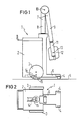
- FIG. 1 shows a mobile x-ray device (1) with a carriage (2) which is provided with two wheels (3) and two steering wheels (4) and which can be moved on the floor (5).
- the steering wheels (4) are attached to a boom (6) extending from the carriage (2).
- the x-ray device (1) is provided with a double arm (7), one arm part (8) of which is attached to the top of the carriage (2) in an approximately vertical position and the other arm part (9) with the arm part (8) around one Axis (10) is pivotally connected.
- the arm part (9) carries, via a holder (11), an X-ray tube (12) which is attached to the holder (11) so as to be rotatable about an axis (13).
- the X-ray tube (12) is shown in its parked position in this FIG.
- the boom (6) serves as a support for the carriage (2) when the arm part (9) with the X-ray tube (12) is pivoted about the axis (10) into a working position.
- a support device (14) for the X-ray device (1) is arranged in the lower region of the carriage (2) between the wheels (3). The support device (14) will be described in more detail later.
- FIG. 2 shows how the support device (14) is attached between the impellers (3).
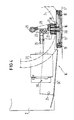
- FIG. 3 shows the support device (14), which is provided with a support plate (15) with a bearing pin (16) which is pivotally mounted in a spherical bearing (17).
- the support plate (15) is spring-mounted by means of a spring (18) which is arranged around the bearing pin (16) between the support plate (15) and the bearing (17).
- the lower side of the support plate (15) is also provided with a number of rubber plugs (19).
- the bearing (17) is rotatable about an axis (20) which connects this bearing (17) to the free end of an arm (21) of a two-part articulated arm (21, 22).
- the free end of the arm (22) of the two-part articulated arm (21, 22) is around an axis (23) which is fixed to the carriage (2), rotatable.
- the axis (20) is also attached to a bracket (24) which in turn is rotatably connected to the carriage (2) by means of an axis (25).
- a drive rod (26) is fastened to the arm (22) of the two-part articulated arm (21, 22) and is driven by an electromagnet (27) which is rotatably fastened to the bracket (24) by means of an axis (28).
- FIG. 4 shows the support device (14) when the support plate (15) is in its lowered position. This position is reached when the electromagnet (27) is activated. When activated, the electromagnet (27) moves the drive rod (26), which presses against the two-part articulated arm (21, 22) in such a way that the articulated arm (21, 22) is aligned. At the same time, the console (24) inevitably rotates about the axis (25). When the support plate (15) is in its lowered position, it lies in the center between the impellers (3), as shown in FIG. 2.
- the X-ray device (1) can be easily rotated around the support plate (15) be, the wheels (3) serve as a floor support.
- the X-ray tube (12) can be positioned in a quick and simple manner.
- the electromagnet (27) with the drive rod (26) can be replaced, for example, with an electric motor with a spindle.
- the support device (14) can lift the X-ray device (1) in such a way that the wheels (3, 4) also go free from the ground. In this embodiment, it is not necessary that the support plate (15) is in its lowered position in the center between the wheels (3).
Abstract
Description
Die Erfindung betrifft ein mobiles Röntgengerat mit einer Röntgenröhre, die über eine Armvorrichtung an einem Wagen befestigt ist, der mit Rädern versehen und auf dem Boden fahrbar ist, wobei die Röntgenröhre in der Längsrichtung des Wagens und in der Höhe verstellbar ist.The invention relates to a mobile x-ray device with an x-ray tube, which is fastened via an arm device to a trolley, which is provided with wheels and can be moved on the floor, the x-ray tube being adjustable in the longitudinal direction of the trolley and in height.
Ein mobiles Röntgengerät dieser Art ist durch den Siemens-Prospekt Mobilett II bekannt. Die Armvorrichtung besteht aus einem Armteil, an dem die Röntgenröhre befestigt ist, und der mit einem zweiten Armteil, der an der Oberseite des Wagens angebracht ist, schwenkbar verbunden ist. Der Wagen ist mit einem Ausleger versehen, der als Stütze dient, wenn die Röntgenröhre in ihre Längsrichtung bzw. in der Höhe eingestellt wird.A mobile X-ray device of this type is known from the Siemens brochure Mobilett II. The arm device consists of an arm part to which the X-ray tube is attached and which is pivotally connected to a second arm part which is attached to the top of the carriage. The carriage is equipped with a boom that serves as a support when the X-ray tube is adjusted in its longitudinal direction or in height.
Bei einer Röntgenaufnahme wird das mobile Röntgengerät zu einem bettlägrigen Patienten gefahren. Bei der Positionierung der Röntgenröhre ist sehr häufig eine Längs- und eine Seitenverschiebung der Röntgenröhre erforderlich.With an x-ray, the mobile x-ray device is moved to a bedridden patient. When positioning the x-ray tube, it is very often necessary to shift the x-ray tube lengthways and sideways.
Der Erfindung liegt die Aufgabe zugrunde, ein mobiles Röntgengerät der eingangs genannten Art zu schaffen, bei dem eine Positionierung der Röntgenröhre in einer raschen und einfachen Weise vorgenommen werden kann.The invention has for its object to provide a mobile X-ray device of the type mentioned, in which the X-ray tube can be positioned in a quick and easy manner.
Diese Aufgabe ist erfindungsgemäß dadurch gelöst, daß am Wagen eine zum Boden absenkbare derart gelagerte Abstützvorrichtung angeordnet ist, daß diese in ihrer abgesenkten Lage das Röntgengerät so abstützt, daß dieses um die Abstützvorrichtung drehbar ist. Durch die Erfindung kann die Röntgenröhre einfach positioniert werden gleichzeitig damit, daß der Wagen in eine Position gebracht wird, in der er bei einer Drehung nicht gegen ein Bett oder einen anderen Gegenstand stößt.This object is achieved in that a support device which can be lowered to the ground is arranged on the carriage in such a way that in its lowered position it supports the X-ray device in such a way that it can be rotated about the support device. With the invention, the x-ray tube can be easily positioned at the same time that the carriage is brought into a position in that he doesn’t hit a bed or other object while turning.
Es ist zwar durch die US-PS 3 790 905 bekannt, daß eine Röntgenröhre eines mobilen Röntgengerätes in seiner Längsrichtung und seitlich verschiebbar ist, ohne den Wagen des Röntgengerätes zu bewegen. Die Röntgenröhre ist an einem horizontal angeordneten Teleskoparm befestigt, der an einer vertikalen Säule angebracht ist, die um ihre Achse drehbar und mit dem Wagen verbunden ist. Die Röntgenröhre kann hierdurch in solche Lagen positioniert werden, in denen der Schwerpunkt des Röntgengerätes erheblich versetzt wird. Dies führt mit sich, daß die Abstützfläche gegen den Boden in allen Richtungen verhältnismäßig groß sein muß, um zu verhindern, daß das Gerät umkippt. Mit einem solchen Röntgengerät ist es schwer, zwischen den Betten zu manövrieren.It is known from US Pat. No. 3,790,905 that an X-ray tube of a mobile X-ray device can be moved in its longitudinal direction and laterally without moving the carriage of the X-ray device. The x-ray tube is attached to a horizontally arranged telescopic arm which is attached to a vertical column which is rotatable about its axis and connected to the carriage. The x-ray tube can hereby be positioned in positions in which the center of gravity of the x-ray device is significantly shifted. This means that the support surface against the ground must be relatively large in all directions to prevent the device from tipping over. With such an X-ray machine, it is difficult to maneuver between the beds.
In einer vorteilhaften Ausbildung der Erfindung wird vorgeschlagen, daß die Abstützvorrichtung das Röntgengerät derart anhebt, daß die Räder vom Boden abheben. Dadurch wird eine gegenüber dem Boden reibungsfreie Drehung des Röntengerätes erreicht.In an advantageous embodiment of the invention, it is proposed that the support device raise the X-ray device in such a way that the wheels lift off the ground. This ensures that the X-ray machine rotates smoothly against the ground.
Die Abstützvorrichtung kann auch so ausgebildet werden, daß sie die Räder derart entlastet, daß diese bei einer Drehung des Röntgengerätes um die Abstützvorrichtung als Bodenstützen dienen.The support device can also be designed such that it relieves the wheels in such a way that they serve as floor supports when the X-ray device is rotated around the support device.
In einer weiteren Ausbildung der Erfindung wird vorgeschlagen, daß die Abstützvorrichtung mittels einer Antriebsvorrichtung in der Höhe verstellbar ist. Hierdurch können die Bewegungen der Abstützvorrichtung in einfacher Weise gesteuert werden.In a further embodiment of the invention it is proposed that the support device can be adjusted in height by means of a drive device. As a result, the movements of the support device can be controlled in a simple manner.
In einer konstruktiv einfachen Ausgestaltung der Erfindung wird vorschlagen, daß die Abstützvorrichtung mit einer Abstützplatte versehen ist, die an dem einen Ende eines zweiteiligen Gelenkarmes angebracht ist, dessen anderes Ende mit dem Wagen drehbar verbunden ist. Der zweiteilige Gelenkarm kann mit Hilfe der Antriebsvorrichtung zusammengeklappt bzw. auseinandergeklappt werden, wodurch die Abstützplatte in der Höhe verstellbar ist.In a structurally simple embodiment of the invention, it will be proposed that the support device be provided with a support plate which is attached to one end of a two-part articulated arm, the other end of which is rotatably connected to the carriage. The two-part articulated arm can be folded or unfolded with the aid of the drive device, as a result of which the height of the support plate can be adjusted.
Eine günstige Ausgestaltung der Erfindung ergibt sich, wenn die Abstützplatte mit einer Welle versehen ist, die an einem sphärischen Lager befestigt ist, das seinerseits am Lenkarm angebracht ist. Dadurch ist erreicht, daß die Abstützplatte sich auch an einen etwas unebenen Boden anpaßt.A favorable embodiment of the invention results if the support plate is provided with a shaft which is fastened to a spherical bearing which in turn is attached to the steering arm. This ensures that the support plate also adapts to a somewhat uneven floor.
Im Hinblick auf eine vorteilhafte Weiterbildung der Erfindung wird vorgeschlagen, daß die Abstützplatte an der Abstützvorrichtung federnd gelagert ist. Hierdurch wird erreicht, daß die Abstützplatte auch bei unterschiedlichen bzw. ungleichmäßigen Bodenbelägen überall mit annähernd gleichem Druck anliegt.With regard to an advantageous development of the invention, it is proposed that the support plate be resiliently mounted on the support device. This ensures that the support plate rests with approximately the same pressure everywhere even with different or uneven floor coverings.
Die Erfindung ist nachfolgend anhand von mehreren, in den Zeichnungen dargestellten Ausführungsbeispielen näher erläutert. Es zeigen:
- FIG 1 eine Seitenansicht eines mobilen Röntgengerätes mit einer Abstützvorrichtung nach der Erfindung
- FIG 2 eine Draufsicht des in der FIG 1 dargestellten mobilen Röntgengerätes und
- FIG 3 und 4 Seitenansichten einer Abstützvorrichtung nach der Erfindung.
- 1 shows a side view of a mobile X-ray device with a support device according to the invention
- 2 shows a plan view of the mobile x-ray device shown in FIG
- 3 and 4 are side views of a support device according to the invention.
In der FIG 1 ist ein mobiles Röntgengerät (1) gezeigt mit einem Wagen (2), der mit zwei Laufrädern (3) und zwei Lenkrädern (4) versehen ist und der auf dem Boden (5) fahrbar ist. Die Lenkräder (4) sind an einem vom Wagen (2) ausgehenden Ausleger (6) befestigt. Das Röntgengerät (1) ist mit einem Doppelarm (7) versehen, dessen einer Armteil (8) an der Oberseite des Wagens (2) in einer etwa vertikalen Lage befestigt ist und dessen anderer Armteil (9) mit dem Armteil (8) um eine Achse (10) schwenkbar verbunden ist. Der Armteil (9) trägt über eine Halterung (11) eine Röntgenröhre (12), die um eine Achse (13) drehbar an der Halterung (11) befestigt ist. Die Röntgenröhre (12) wird in dieser FIG 1 in ihrer Parklage gezeigt. Der Ausleger (6) dient als Stütze für den Wagen (2), wenn der Armteil (9) mit der Röntgenröhre (12) um die Achse (10) in eine Arbeitslage geschwenkt wird. Im unteren Bereich des Wagens (2) zwischen den Laufrädern (3) ist eine Abstützvorrichtung (14) für das Röntgengerät (1) angeordnet. Die Abstützvorrichtung (14) wird später näher beschrieben.1 shows a mobile x-ray device (1) with a carriage (2) which is provided with two wheels (3) and two steering wheels (4) and which can be moved on the floor (5). The steering wheels (4) are attached to a boom (6) extending from the carriage (2). The x-ray device (1) is provided with a double arm (7), one arm part (8) of which is attached to the top of the carriage (2) in an approximately vertical position and the other arm part (9) with the arm part (8) around one Axis (10) is pivotally connected. The arm part (9) carries, via a holder (11), an X-ray tube (12) which is attached to the holder (11) so as to be rotatable about an axis (13). The X-ray tube (12) is shown in its parked position in this FIG. The boom (6) serves as a support for the carriage (2) when the arm part (9) with the X-ray tube (12) is pivoted about the axis (10) into a working position. A support device (14) for the X-ray device (1) is arranged in the lower region of the carriage (2) between the wheels (3). The support device (14) will be described in more detail later.
In der FIG 2 ist dargestellt, wie die Abstützvorrichtung (14) zwischen den Laufrädern (3) angebracht ist.FIG. 2 shows how the support device (14) is attached between the impellers (3).
In der FIG 3 ist die Abstützvorrichtung (14) gezeigt, die mit einer Abstützplatte (15) mit einem Lagerbolzen (16) versehen ist, der in einem sphärischen Lager (17) schwenkbar gelagert ist. Die Abstützplatte (15) ist mittels einer Feder (18), die um den Lagerbolzen (16) zwischen der Abstützplatte (15) und dem Lager (17) angeordnet ist, federnd gelagert. Die untere Seite der Abstützplatte (15) ist außerdem mit einer Anzahl Gummistöpsel (19) versehen. Das Lager (17) ist um eine Achse (20) drehbar, die dieses Lager (17) mit dem freien Ende eines Armes (21) eines zweiteiligen Gelenkarmes (21,22) verbindet. Das freie Ende des Armes (22) des zweiteiligen Gelenkarmes (21,22) ist um eine Achse (23), die am Wagen (2) befestigt ist, drehbar. Die Achse (20) ist außerdem an einer Konsole (24) angebracht, die ihrerseits mittels einer Achse (25) mit dem Wagen (2) drehbar verbunden ist. Am Arm (22) des zweiteiligen Gelenkarmes (21,22) ist eine Antriebsstange (26) befestigt, die von einem Elektromagneten (27) angetrieben wird, der an der Konsole (24) mittels einer Achse (28) drehbar befestigt ist.3 shows the support device (14), which is provided with a support plate (15) with a bearing pin (16) which is pivotally mounted in a spherical bearing (17). The support plate (15) is spring-mounted by means of a spring (18) which is arranged around the bearing pin (16) between the support plate (15) and the bearing (17). The lower side of the support plate (15) is also provided with a number of rubber plugs (19). The bearing (17) is rotatable about an axis (20) which connects this bearing (17) to the free end of an arm (21) of a two-part articulated arm (21, 22). The free end of the arm (22) of the two-part articulated arm (21, 22) is around an axis (23) which is fixed to the carriage (2), rotatable. The axis (20) is also attached to a bracket (24) which in turn is rotatably connected to the carriage (2) by means of an axis (25). A drive rod (26) is fastened to the arm (22) of the two-part articulated arm (21, 22) and is driven by an electromagnet (27) which is rotatably fastened to the bracket (24) by means of an axis (28).
In der FIG 4 ist die Abstützvorrichtung (14) dargestellt, wenn sich die Abstützplatte (15) in ihrer abgesenkten Lage befindet. Diese Lage wird erreicht, wenn der Elektromagnet (27) aktiviert wird. Der Elektromagnet (27) verschiebt bei einer Aktivierung die Antriebsstange (26), die gegen den zweiteiligen Gelenkarm (21,22) drückt derart, daß der Gelenkarm (21,22) ausgerichtet wird. Gleichzeitig dreht sich die Konsole (24) zwangsläufig um die Achse (25). Wenn die Abstützplatte (15) sich in ihrer abgesenkten Lage befindet, liegt sie im Zentrum zwischen den Laufrädern (3), wie es in der FIG 2 gezeigt ist. Wenn nun die Abstützplatte (15) mit Hilfe des sphärischen Lagers (17) und der Feder (18) dicht am Boden (5) liegt und die Laufräder (3) entlastet, kann das Röntgengerät (1) leicht um die Abstützplatte (15) gedreht werden, wobei die Laufräder (3) als Bodenstütze dienen. Durch diese Arretierung des Röntgengerätes (1) gleichzeitig damit, daß es drehbar ist, kann eine Positionierung der Röntgenröhre (12) in einer schnellen und einfachen Weise erfolgen.4 shows the support device (14) when the support plate (15) is in its lowered position. This position is reached when the electromagnet (27) is activated. When activated, the electromagnet (27) moves the drive rod (26), which presses against the two-part articulated arm (21, 22) in such a way that the articulated arm (21, 22) is aligned. At the same time, the console (24) inevitably rotates about the axis (25). When the support plate (15) is in its lowered position, it lies in the center between the impellers (3), as shown in FIG. 2. If the support plate (15) with the help of the spherical bearing (17) and the spring (18) is close to the ground (5) and relieves the wheels (3), the X-ray device (1) can be easily rotated around the support plate (15) be, the wheels (3) serve as a floor support. By locking the X-ray device (1) simultaneously with the fact that it can be rotated, the X-ray tube (12) can be positioned in a quick and simple manner.
Wenn die Röntgenuntersuchung beendet ist, wird der Strom zum Elektromagneten (27) ausgeschaltet, wobei eine Zugfeder (29), deren eines Ende an der Achse (23) und deren anderes Ende an der Konsole angebracht ist, den zweiteiligen Gelenkarm (21,22) zusammenklappt, so daß die Antriebsstange (27) in den Elektromagneten (27) hineingeschoben wird und die Abstützplatte (15) in ihre Ausgangslage zurückgeht. Als Antrieb für die Abstützvorrichtung (14) kann der Elektromagnet (27) mit der Antriebsstange (26) z.B. mit einem elektrischen Motor mit einer Spindel ersetzt werden.When the x-ray examination is complete, the current to the electromagnet (27) is switched off, and a tension spring (29), one end of which is attached to the axis (23) and the other end of which is attached to the console, the two-part articulated arm (21, 22). collapses so that the drive rod (27) is pushed into the electromagnet (27) and the support plate (15) in its starting position goes back. As a drive for the support device (14), the electromagnet (27) with the drive rod (26) can be replaced, for example, with an electric motor with a spindle.
In einer weiteren Ausführungsform, die nicht dargestellt ist, kann die Abstützvorrichtung (14) das Röntgengerät (1) derart heben, daß auch die Räder (3,4) vom Boden frei gehen. In diesem Ausführungsbeispiel ist es nicht notwendig, daß die Abstützplatte (15) in ihrer abgesenkten Lage im Zentrum zwischen den Laufrädern (3) liegt.In a further embodiment, which is not shown, the support device (14) can lift the X-ray device (1) in such a way that the wheels (3, 4) also go free from the ground. In this embodiment, it is not necessary that the support plate (15) is in its lowered position in the center between the wheels (3).
- 1 mobiles Röntgengerät1 mobile x-ray machine
- 2 Wagen2 carriages
- 3 Laufrad3 impeller
- 4 Lenkrad4 steering wheel
- 5 Boden5 floor
- 6 Ausleger6 outriggers
- 7 Doppelarm7 double arm
- 8 Armteil8 arm part
- 9 Armteil9 arm part
- 10 Achse10 axis
- 11 Halterung11 bracket
- 12 Röntgenröhre12 x-ray tube
- 13 Achse13 axis
- 14 Abstützvorrichtung14 support device
- 15 Abstützplatte15 support plate
- 16 Lagerbolzen, Welle16 bearing bolts, shaft
- 17 Lager17 bearings
- 18 Feder18 spring
- 19 Gummistöpsel19 rubber plugs
- 20 Achse20 axis
- 21 Gelenkarm, Arm21 articulated arm, arm
- 22 Gelenkarm, Arm22 articulated arm, arm
- 23 Achse23 axis
- 24 Konsole24 console
- 25 Achse25 axis
- 26 Antriebsstange26 drive rod
- 27 Elektromagnet27 electromagnet
- 28 Achse28 axis
- 29 Zugfeder29 tension spring
Claims (10)
Applications Claiming Priority (2)
| Application Number | Priority Date | Filing Date | Title |
|---|---|---|---|
| SE8902332A SE462892B (en) | 1989-06-28 | 1989-06-28 | MOBILE ROENT GENERATOR |
| SE8902332 | 1989-06-28 |
Publications (2)
| Publication Number | Publication Date |
|---|---|
| EP0405234A1 true EP0405234A1 (en) | 1991-01-02 |
| EP0405234B1 EP0405234B1 (en) | 1994-02-02 |
Family
ID=20376416
Family Applications (1)
| Application Number | Title | Priority Date | Filing Date |
|---|---|---|---|
| EP90111214A Expired - Lifetime EP0405234B1 (en) | 1989-06-28 | 1990-06-13 | Mobile X-ray apparatus |
Country Status (5)
| Country | Link |
|---|---|
| US (1) | US5081662A (en) |
| EP (1) | EP0405234B1 (en) |
| JP (1) | JP2809823B2 (en) |
| DE (1) | DE59004475D1 (en) |
| SE (1) | SE462892B (en) |
Cited By (4)
| Publication number | Priority date | Publication date | Assignee | Title |
|---|---|---|---|---|
| US6270047B1 (en) | 1998-11-06 | 2001-08-07 | Compx International Inc. | Keyboard tilt mechanism |
| US6336618B1 (en) | 1999-10-15 | 2002-01-08 | Compx International Inc | Adjustable computer keyboard platform support mechanism |
| US6336617B1 (en) | 1998-11-06 | 2002-01-08 | Peter Barber | Ratchet tilt mechanism |
| DE102011082607A1 (en) | 2011-09-13 | 2013-03-14 | Siemens Aktiengesellschaft | Device for receiving wireless operating electronic device, particularly wireless operating flat detector of X-ray device, has compatible contact elements and reflection light sensor, which is arranged opposite to activated reflector |
Families Citing this family (23)
| Publication number | Priority date | Publication date | Assignee | Title |
|---|---|---|---|---|
| FR2679124B1 (en) * | 1991-07-19 | 1993-11-19 | General Electric Cgr Sa | RADIOLOGICAL MOBILE. |
| US5283823A (en) * | 1991-11-27 | 1994-02-01 | X-Cel X-Ray Corporation | Portable radiographic device |
| US5388142A (en) * | 1991-11-27 | 1995-02-07 | X-Cel X-Ray Corporation | Portable radiographic device |
| US5425069A (en) * | 1993-11-26 | 1995-06-13 | Lorad Corporation | Mobile X-ray apparatus |
| US5503416A (en) * | 1994-03-10 | 1996-04-02 | Oec Medical Systems, Inc. | Undercarriage for X-ray diagnostic equipment |
| US5924664A (en) | 1997-03-12 | 1999-07-20 | Ergo View Technologies Corp. | Keyboard support mechanism |
| FI116655B (en) * | 1999-06-30 | 2006-01-13 | Instrumentarium Oy | Mobile x-ray device |
| JP4824161B2 (en) * | 2000-12-28 | 2011-11-30 | 株式会社サトー | Handy terminal portable carrier |
| US20040146142A1 (en) * | 2003-01-29 | 2004-07-29 | Miikka Maijala | Mobile X-ray apparatus |
| US7587027B2 (en) * | 2006-12-23 | 2009-09-08 | X-Cel X-Ray | Method and apparatus for determining and displaying x-ray radiation by a radiographic device |
| CN101278840B (en) * | 2007-04-02 | 2012-02-22 | Ge医疗系统环球技术有限公司 | X-ray photographic equipment |
| US7585109B2 (en) * | 2007-11-21 | 2009-09-08 | X-Cel X-Ray | Arm linkage system for a radiographic device |
| US11944469B2 (en) | 2010-03-12 | 2024-04-02 | Mobius Imaging Llc | Caster system for mobile apparatus |
| US9801592B2 (en) | 2013-03-15 | 2017-10-31 | Mobius Imaging, Llc | Caster system for mobile apparatus |
| EP2544592B1 (en) | 2010-03-12 | 2020-03-25 | Mobius Imaging, Llc | Drive system for imaging device |
| JP6000787B2 (en) * | 2012-09-28 | 2016-10-05 | キヤノン株式会社 | Radiographic imaging apparatus and method for controlling radiographic imaging apparatus |
| WO2014143796A2 (en) | 2013-03-15 | 2014-09-18 | Mobius Imaging, Llc | Mobile x-ray imaging system |
| US9177681B2 (en) | 2014-03-31 | 2015-11-03 | X-Cel X-Ray Corporation | Base for radiographic device |
| DE102014214513A1 (en) * | 2014-07-24 | 2016-01-28 | Siemens Aktiengesellschaft | Adjustable foot of a CT system for positioning the CT system on a surface and CT system |
| US10271802B2 (en) * | 2014-08-12 | 2019-04-30 | Carestream Health, Inc. | Digital x-ray imaging apparatus and method |
| CN107920799B (en) | 2015-09-04 | 2021-06-15 | 马科外科公司 | Bracket for portable surgical robot |
| JP6066247B1 (en) * | 2015-11-26 | 2017-01-25 | 富士フイルム株式会社 | Radiation irradiation equipment |
| CN110840474B (en) * | 2019-11-26 | 2022-12-16 | 上海联影医疗科技股份有限公司 | Medical camera frame and medical camera system |
Citations (3)
| Publication number | Priority date | Publication date | Assignee | Title |
|---|---|---|---|---|
| US3790805A (en) * | 1971-04-19 | 1974-02-05 | Picker Corp | Mobile x-ray unit |
| US4223230A (en) * | 1977-10-12 | 1980-09-16 | Siemens Aktiengesellschaft | X-Ray examination apparatus |
| US4326131A (en) * | 1977-10-03 | 1982-04-20 | Siemens Aktiengesellschaft | Mobile x-ray apparatus |
Family Cites Families (3)
| Publication number | Priority date | Publication date | Assignee | Title |
|---|---|---|---|---|
| US1239145A (en) * | 1914-01-29 | 1917-09-04 | Victor Electric Corp | X-ray apparatus. |
| SE418869B (en) * | 1973-02-15 | 1981-06-29 | Voest Ag | TRANSPORT LIFT FOR THE CONVERTER CHANGE |
| US3801798A (en) * | 1973-05-17 | 1974-04-02 | Wagner Electric Corp | Power transfer circuit for momentarily energizing keyable control circuits |
-
1989
- 1989-06-28 SE SE8902332A patent/SE462892B/en not_active IP Right Cessation
-
1990
- 1990-06-13 EP EP90111214A patent/EP0405234B1/en not_active Expired - Lifetime
- 1990-06-13 DE DE90111214T patent/DE59004475D1/en not_active Expired - Fee Related
- 1990-06-22 JP JP2163049A patent/JP2809823B2/en not_active Expired - Fee Related
- 1990-06-27 US US07/544,313 patent/US5081662A/en not_active Expired - Lifetime
Patent Citations (3)
| Publication number | Priority date | Publication date | Assignee | Title |
|---|---|---|---|---|
| US3790805A (en) * | 1971-04-19 | 1974-02-05 | Picker Corp | Mobile x-ray unit |
| US4326131A (en) * | 1977-10-03 | 1982-04-20 | Siemens Aktiengesellschaft | Mobile x-ray apparatus |
| US4223230A (en) * | 1977-10-12 | 1980-09-16 | Siemens Aktiengesellschaft | X-Ray examination apparatus |
Cited By (6)
| Publication number | Priority date | Publication date | Assignee | Title |
|---|---|---|---|---|
| US6270047B1 (en) | 1998-11-06 | 2001-08-07 | Compx International Inc. | Keyboard tilt mechanism |
| US6336617B1 (en) | 1998-11-06 | 2002-01-08 | Peter Barber | Ratchet tilt mechanism |
| US6336618B1 (en) | 1999-10-15 | 2002-01-08 | Compx International Inc | Adjustable computer keyboard platform support mechanism |
| US6460816B1 (en) | 1999-10-15 | 2002-10-08 | Compx International, Inc. | Adjustable computer keyboard platform support mechanism |
| DE102011082607A1 (en) | 2011-09-13 | 2013-03-14 | Siemens Aktiengesellschaft | Device for receiving wireless operating electronic device, particularly wireless operating flat detector of X-ray device, has compatible contact elements and reflection light sensor, which is arranged opposite to activated reflector |
| DE102011082607B4 (en) * | 2011-09-13 | 2017-08-03 | Siemens Healthcare Gmbh | Recording device for a wireless operable electronic device, in particular a flat detector of an X-ray device, and mobile X-ray device |
Also Published As
| Publication number | Publication date |
|---|---|
| SE8902332A (en) | 1990-09-17 |
| JP2809823B2 (en) | 1998-10-15 |
| US5081662A (en) | 1992-01-14 |
| SE462892B (en) | 1990-09-17 |
| JPH0337998A (en) | 1991-02-19 |
| SE8902332D0 (en) | 1989-06-28 |
| DE59004475D1 (en) | 1994-03-17 |
| EP0405234B1 (en) | 1994-02-02 |
Similar Documents
| Publication | Publication Date | Title |
|---|---|---|
| EP0405234B1 (en) | Mobile X-ray apparatus | |
| DE4423402C2 (en) | Support column for holding a patient support surface | |
| EP0321822B1 (en) | Ceiling mount for supporting medical equipment | |
| DE1474238B2 (en) | DEVICE FOR SUPPORTING A HEAVY ROLLER ABOVE THE GROUND | |
| EP0146096B1 (en) | Lifting-turntable device | |
| DE3719012A1 (en) | RACK TO HOLD A WORKTOP | |
| DE2061662B2 (en) | Ceiling mounted movable support for medical instruments - has parallelogram linkage with power drive for horizontal platform | |
| DE3408172C2 (en) | ||
| DE60314682T2 (en) | Tire assembly and bead press machine for commercial vehicle wheels | |
| DE2046207A1 (en) | Device for carrying and positio ren of patients | |
| DE2509805B2 (en) | TUBE HOLE DRILLING OR PLUGGING MACHINE FOR SHAFT, IN PARTICULAR BIG FURNACE | |
| EP0565833A1 (en) | Device for perpendicularly aligning the upright axis of a superstructure turnably and inclinably mounted on an understructure | |
| DE2165244C2 (en) | Device for lifting and tipping motor vehicles | |
| EP0125713A2 (en) | X-ray apparatus tiltable on a horizontal axis | |
| DE889363C (en) | Three-wheel lifting cart with power drive | |
| DE1455615B2 (en) | Device for lifting tractors provided with working machines | |
| DE2361566C3 (en) | Drilling device | |
| DE2227406C3 (en) | Mobile turntable ladder | |
| DE2352159C3 (en) | Lifting device for automobiles | |
| EP0419950B1 (en) | X-ray examination apparatus | |
| DE2330528A1 (en) | DEVICE FOR CHANGING TIRES ON VEHICLE WHEELS | |
| EP0159526A1 (en) | Apparatus for cutting flat materials | |
| DE10147717A1 (en) | Device for supporting workpieces comprises a scissor-like elevating platform mounted on a horizontal turntable forming part of a rotating device, drive devices, an elevating platform plate, and a control column | |
| DE2830515C2 (en) | Device for the automatic control of the adjusting rings provided on the bogie of a height-adjustable working device for the vertical alignment of the vertical axis of the device structure connected via the bogie | |
| EP1227299B1 (en) | Apparatus for measuring the symmetry of a vehicle body |
Legal Events
| Date | Code | Title | Description |
|---|---|---|---|
| PUAI | Public reference made under article 153(3) epc to a published international application that has entered the european phase |
Free format text: ORIGINAL CODE: 0009012 |
|
| AK | Designated contracting states |
Kind code of ref document: A1 Designated state(s): DE FR GB SE |
|
| 17P | Request for examination filed |
Effective date: 19901205 |
|
| 17Q | First examination report despatched |
Effective date: 19930517 |
|
| GRAA | (expected) grant |
Free format text: ORIGINAL CODE: 0009210 |
|
| AK | Designated contracting states |
Kind code of ref document: B1 Designated state(s): DE FR GB SE |
|
| PG25 | Lapsed in a contracting state [announced via postgrant information from national office to epo] |
Ref country code: SE Effective date: 19940202 |
|
| REF | Corresponds to: |
Ref document number: 59004475 Country of ref document: DE Date of ref document: 19940317 |
|
| GBT | Gb: translation of ep patent filed (gb section 77(6)(a)/1977) |
Effective date: 19940408 |
|
| ET | Fr: translation filed | ||
| PLBE | No opposition filed within time limit |
Free format text: ORIGINAL CODE: 0009261 |
|
| STAA | Information on the status of an ep patent application or granted ep patent |
Free format text: STATUS: NO OPPOSITION FILED WITHIN TIME LIMIT |
|
| 26N | No opposition filed | ||
| PGFP | Annual fee paid to national office [announced via postgrant information from national office to epo] |
Ref country code: GB Payment date: 19980511 Year of fee payment: 9 |
|
| PG25 | Lapsed in a contracting state [announced via postgrant information from national office to epo] |
Ref country code: GB Free format text: LAPSE BECAUSE OF NON-PAYMENT OF DUE FEES Effective date: 19990613 |
|
| GBPC | Gb: european patent ceased through non-payment of renewal fee |
Effective date: 19990613 |
|
| PGFP | Annual fee paid to national office [announced via postgrant information from national office to epo] |
Ref country code: FR Payment date: 20030627 Year of fee payment: 14 |
|
| PGFP | Annual fee paid to national office [announced via postgrant information from national office to epo] |
Ref country code: DE Payment date: 20030818 Year of fee payment: 14 |
|
| PG25 | Lapsed in a contracting state [announced via postgrant information from national office to epo] |
Ref country code: DE Free format text: LAPSE BECAUSE OF NON-PAYMENT OF DUE FEES Effective date: 20050101 |
|
| PG25 | Lapsed in a contracting state [announced via postgrant information from national office to epo] |
Ref country code: FR Free format text: LAPSE BECAUSE OF NON-PAYMENT OF DUE FEES Effective date: 20050228 |
|
| REG | Reference to a national code |
Ref country code: FR Ref legal event code: ST |