EP0408757A1 - Laser beam transmitting member and method of manufacturing the same - Google Patents
Laser beam transmitting member and method of manufacturing the same Download PDFInfo
- Publication number
- EP0408757A1 EP0408757A1 EP90900333A EP90900333A EP0408757A1 EP 0408757 A1 EP0408757 A1 EP 0408757A1 EP 90900333 A EP90900333 A EP 90900333A EP 90900333 A EP90900333 A EP 90900333A EP 0408757 A1 EP0408757 A1 EP 0408757A1
- Authority
- EP
- European Patent Office
- Prior art keywords
- laser light
- transmissible
- surface layer
- probe
- particles
- Prior art date
- Legal status (The legal status is an assumption and is not a legal conclusion. Google has not performed a legal analysis and makes no representation as to the accuracy of the status listed.)
- Granted
Links
Images


Classifications
-
- A—HUMAN NECESSITIES
- A61—MEDICAL OR VETERINARY SCIENCE; HYGIENE
- A61B—DIAGNOSIS; SURGERY; IDENTIFICATION
- A61B18/00—Surgical instruments, devices or methods for transferring non-mechanical forms of energy to or from the body
- A61B18/18—Surgical instruments, devices or methods for transferring non-mechanical forms of energy to or from the body by applying electromagnetic radiation, e.g. microwaves
- A61B18/20—Surgical instruments, devices or methods for transferring non-mechanical forms of energy to or from the body by applying electromagnetic radiation, e.g. microwaves using laser
- A61B18/22—Surgical instruments, devices or methods for transferring non-mechanical forms of energy to or from the body by applying electromagnetic radiation, e.g. microwaves using laser the beam being directed along or through a flexible conduit, e.g. an optical fibre; Couplings or hand-pieces therefor
-
- A—HUMAN NECESSITIES
- A61—MEDICAL OR VETERINARY SCIENCE; HYGIENE
- A61B—DIAGNOSIS; SURGERY; IDENTIFICATION
- A61B18/00—Surgical instruments, devices or methods for transferring non-mechanical forms of energy to or from the body
-
- A—HUMAN NECESSITIES
- A61—MEDICAL OR VETERINARY SCIENCE; HYGIENE
- A61B—DIAGNOSIS; SURGERY; IDENTIFICATION
- A61B18/00—Surgical instruments, devices or methods for transferring non-mechanical forms of energy to or from the body
- A61B18/18—Surgical instruments, devices or methods for transferring non-mechanical forms of energy to or from the body by applying electromagnetic radiation, e.g. microwaves
- A61B18/20—Surgical instruments, devices or methods for transferring non-mechanical forms of energy to or from the body by applying electromagnetic radiation, e.g. microwaves using laser
- A61B18/22—Surgical instruments, devices or methods for transferring non-mechanical forms of energy to or from the body by applying electromagnetic radiation, e.g. microwaves using laser the beam being directed along or through a flexible conduit, e.g. an optical fibre; Couplings or hand-pieces therefor
- A61B2018/2255—Optical elements at the distal end of probe tips
- A61B2018/2261—Optical elements at the distal end of probe tips with scattering, diffusion or dispersion of light
Definitions
- This invention relates to a laser light transmissible substance such as a laser light emitter which permits, for living tissue of an animal such as a human body, an incision and vaporization of the living tissue, a thermal therapy, and the like. Further, this invention relates to a producing method of the laser light transmissible substance.
- a method which has been utilized lately is as follows; at first, the laser light is transmitted into an optical fiber. Then, the laser light is fed into an emitting probe, which is brought into or out of contact with the tissue being adjacent to the fore end of the optical fiber. Finally, the laser light emitted from the surface of the probe is irradiated on the tissue.
- Fig. 8 This probe is made of sapphire, quartz and the like, and usually, its surface is smooth.
- laser light L is fed by means of an optical fiber 51 into the probe 50, which is of long and narrow conical shape with a round tip end and whose external surface is smooth.
- the laser light L passing through the probe 50 is reflected and refracted on an inner surface to reach the tip end, finally is emitted only from the tip end.
- a power density of the laser light L is shown as contour lines H. Then, when the probe 50 is brought into contact with the tissue, the distribution of the power density in a longitudinal direction in the tissue is shown as a curve Pd. Accordingly, it is obvious that the laser light L is concentratedly emitted from the tip end of the probe 50. Therefore, the effective area of laser light irradiation is significantly small.
- a rough surface 50a on the external surface of the probe 50A extends the effective area of laser light irradiation, because the laser light is refracted on the rough surface 50a to be emitted in many directions.
- a surface layer 5A made of a light transmissible material is formed on the rough surface 50a for refraction of the laser light.
- this conventional probe and the required power level of the laser light should be changed corresponding to each type of a target area of the tissue and each type of the medical treatment. In other words, it is difficult to apply this conventional probe for various types of medical treatments.
- another object of the present invention is to provide a producing method of this laser light transmissible substance.
- the present invention features a laser light transmissible substance, which has a laser light transmissible member provided on its surface with a surface layer including laser light absorbing particles and light scattering particles having a larger refractive index than that of the transmissible member.
- the surface layer contains a binder for forming a surface layer having high mechanical strength.
- a rough surface is formed on the laser light transmissible member and the surface layer is provided on the rough surface for further extending the effective area of laser light irradiation.
- a producing method of a laser light transmissible substance of the present invention is forming a surface layer on a laser light transmissible member, which comprises making contact the transmissible member with a dispersion including laser light absorbing particles and light scattering particles having a larger refractive index than that of the transmissible member.
- a producing method of a laser light transmissible substance by forming a surface layer on a laser transmissible member comprises the steps of;
- the transmissible member 1 is provided on its surface with the surface layer 5 which contains the light scattering particles 2 made of sapphire and the like having a larger refractive index than that of the transmissible member 1. While the laser light L emitted from the transmissible member 1 passes through the surface layer 5, the laser light L impinges on the light scattering particle 2 in the surface layer 5 to be partially reflected on the surface of the particle 2, or to be partially penetrated into and emitted from the particle 2 with refraction. Therefore, the laser lights L is emitted in various directions from the whole external surface of the surface layer 5. This produces the large area of the laser light irradiation.
- the surface layer 5 contains the laser light absorbing particles 3 made of carbon and the like. Accordingly, when the laser light L impinges on the laser light absorbing particle 3, the greater part of the energy of the laser light L is converted to heat energy by means of the laser light absorbing particle 3, and the tissue is heated by the heat energy from the surface layer 5.
- the tissue can be incised with a low energy of the laser light L penetrated into the transmissible member 1. Therefore, when the tissue is incised, the transmissible member 1 can be moved quickly. Accordingly, the medical treatment can be carried out in short time. Further, since high power level of the laser light L is not required, the medical treatment can be carried out with a cheap and small scaled laser light generator.
- the producing method of the surface layer if a dispersion containing the laser light absorbing particles and the light scattering particles is coated on the surface of the transmissible member, after a vaporization of a dispersion medium, the contact of the laser light transmissible substance serving as a probe having the surface layer with the tissue or other substances causes a damage to the surface layer. Because, the both particles are attached to the surface of the transmissible member only by physical adsorptive power.
- the binder is preferably made of a light transmissible material 4 such as quartz and the like to ensure the emitting of the laser light from the surface layer 5.
- a light transmissible material 4 such as quartz and the like to ensure the emitting of the laser light from the surface layer 5.
- the transmissible material 4 laser light transmissible particles having a melting point same to or lower than that of the transmissible member 1 are used and they are dispersed together with the absorbing particles and the light scattering particles in a proper liquid such as water and alcohol. Then the transmissible member 1 painted with this dispersion is baked at a higher temperature than a melting point of the transmissible particle and within a limit temperature so that the transmissible member 1 can keep its shape. Accordingly, the transmissible particles melt to form the surface layer of high mechanical strength together with the laser light absorbing particles and the light scattering particles. Therefore, the damages to the surface layer can be reduced because of its high strength.
- Fig. 1 is an enlarged sectional view of a surface layer of the present invention
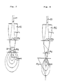
- Fig. 2 is a schematic illustration showing an embodiment of a laser light transmissible substance as a probe for a laser scalpel and a power density distribution diagram of laser light emitted from this probe
- Fig. 3 is an enlarged sectional view of a surface layer formed on a rough surface of a laser light transmissible material
- Fig. 4 is a sectional view of a surface layer on an optical fiber
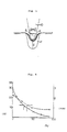
- Fig. 5 is a schematic illustration explaining an experiment of an incision of living tissue with a probe
- Fig. 6 is a graph showing the result of the experiment illustrated in Fig. 5;
- Fig. 6 is a graph showing the result of the experiment illustrated in Fig. 5; Fig.
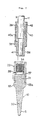
- FIG. 7 is a longitudinal sectional view of an example of a structure of a probe and a holding member therefor;
- Fig. 8 is a schematic illustration showing an embodiment of a conventional probe and a power density distribution diagram of laser light with this conventional probe;
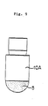
- Fig. 9 is an elevational view of a probe having another shape;
- Fig. 10 is an enlarged sectional view of a surface of a conventional probe.
- Fig. 1 shows an enlarged sectional view of a transmissible substance, which serves as a probe 10 shown in Fig. 2 provided on its surface with a surface layer 5.
- the surface layer 5 contains laser light scattering particles 2 and laser light absorbing particles 3 with laser light transmissible particles which are melted to be a laser light transmissible material 4 as a binder.
- a rough surface 1 a is formed on the transmissible member 1 and the surface layer 5 is provided on the rough surface, the scattering effect of the laser light is increased.
- the probe 10 for example, is held by a holding member shown in Fig. 7.
- This probe 10 comprises a tapered conical inserting portion 30, a main holding portion 31 and a flange 32 formed between them.
- the probe 10 is fitted in a cylindrical female connector 33 and fixed integrally thereto by caulking the mating portions 33a and/or by using a ceramic type adhesive between the mating surfaces.
- the female connector 33 has, on its internal surface, a female thread 34 which is adapted to mate removably with male threads 36 of a male connector 35.
- the female connector 33 has holes 38 which facilitate the passage of cooling water W inside and outside thereof.
- the holes 38 are disposed to be adjacent to the top of a light receiving base 37 of the probe 10 and, for example, oppositely on the circumference of the female connector 33, although only one of them is shown in Fig. 7
- the male connector 35 is pressed to be fitted into an end portion of a flexible tube jacket 39 fabricated of, for example, polytetrafluoroethylene such as Teflon (trademark).
- a flexible tube jacket 39 fabricated of, for example, polytetrafluoroethylene such as Teflon (trademark).
- Teflon trademark
- the male connector 35 has stepped portions 40 at its base portion in order to be firmly held by the tube jacket 39 so as not to be removed.
- a transmitting optical fiber 11 for the laser light is inserted in the tube jacket 39 and the male connector 35. There is a gap 42 between the optical fiber 11 and the tube jacket 39 for supplying cooling water.
- the fore end portion of the transmitting optical fiber 11 is closely fitted in the male connector 35 at its stepped portion 40, however, the stepped portion 40 has, for example, two slits 40a formed oppositely on the circumference of the stepped portion 40 for letting the cooling water W pass through.
- a passage 41 for the cooling water W is further provided between the inner surface of the fore end portion of the male connector 35 and the external surface of the transmitting optical fiber 11.
- This probe held by the above mentioned holding member serves as a laser light emitter while the female connector 33 is connected to mate with the male connector 35.
- the emitter is equipped in an endoscope or some other suitable holders. Then, pulse laser light introduced through the transmitting optical fiber 11 penetrates into the probe 10 from the light receiving base 37, therefore, is emitted from all over the external surface of the inserting portion 30.
- the cooling water W is fed through a gap 42, the slit 40a and a passage 41 to cool the probe 10, further, discharged through the opening 38 to flow out on the surface of the tissue so as to cool it.
- the transmissible member of this invention is preferably fabricated from a natural or artificial ceramic material such as diamond, sapphire, quartz and the like due to their heat resistance.
- the light scattering particle which has a larger refractive index for the laser light than that of the transmissible member, is of a natural or artificial material such as diamond, sapphire, quartz (a melting. point is preferably high), single crystal zirconium oxide (Zr0 2 ), high melting point glass, transmissible and heat resistant synthetic resin, laser light reflective metal, and a particle which is laser light reflective or non-reflective metal particle coated with laser light reflective metal such as gold, aluminum and the like by means of a surface treatment such as gilding.
- a natural or artificial material such as diamond, sapphire, quartz (a melting. point is preferably high), single crystal zirconium oxide (Zr0 2 ), high melting point glass, transmissible and heat resistant synthetic resin, laser light reflective metal, and a particle which is laser light reflective or non-reflective metal particle coated with laser light reflective metal such as gold, aluminum and the like by means of a surface treatment such as gilding.
- the laser light transmissible material of the binder is preferably made from the transmissible particle, which can be melt to form a film and more preferably which has heat resistance, such as natural or artificial sapphire, quartz, glass, transmissible and heat resistant synthetic resin and the like.
- a suitable transmissible material is selected from these materials in consideration of the relation to the transmissible member.
- the laser light absorbing particle is made of carbon, graphite, iron oxide, manganese dioxide and any other materials which can absorb the laser light to generate heat energy.
- a content of each particle in the surface layer(wt%) and each average particle size are preferably within ranges as shown in a following table respectively. More preferable content and particle size are put in parentheses.
- the thickness of the surface layer is preferably l0um - 5mm, more preferably 30pm - lmm.
- the surface layer is formed by one of following methods. If the surface layer can not be formed to be a desired thickness for this once, the operation of the method should be repeated until a desired thickness can be obtained;
- the three kinds of particles are dispersed in a dispersion medium. Then the medium is heated to a temperature which is higher than the melting point of the transmissible particle. Finally, the transmissible member is dipped in the heated dispersion.
- the first method facilitates operation, because what should be done is that only a part of the transmissible member, which is desired to be the surface layer, necessitates being dipped in the dispersion and therefrom pulled up. That is to say, the first method is practical and rational.
- suitable liquid such as water, alcohol or mixture of them can be used. Further sugar or starch is added to increase the viscosity of the dispersion medium.
- the forming of the surface layer 5 on the surface of the transmissible member 1 extends the effective area of laser light irradiation, because, the laser light is emitted widely in many directions from the surface layer 5 as shown in Fig. 2.
- the content of the light scattering particle, that of the transmissible particle, and that of the laser light absorbing particle will be referred as (A), (B) and (C) respectively.
- the inventor investigated each change of following two parameters against (C) under fixed condition of (A) : (B) 2 : 1.
- One investigated parameter is a laser light power level with which an incision to a pig's liver can be started.
- Another is a depth d of a coagulation layer Y below a carbonized layer X. Then, the result of this experiment is obtained as shown in Fig. 6. Then, following things are known.
- the incision can be started with the low power level of the laser light, then it is possible for the probe to be moved quickly. Then, according to the relation of the depth d and the percentage of (C), as the percentage of (C) is increased, the depth d is reduced. Since the effect of hemostasis can be known by the depth d, it is clear that the hemostasis of the treated tissue is reduced as the percentage of (C) is increased.
- the probe with high percentage of (C) in the surface layer can be used effectively for incising the tissue which bear the damage to some extent such as skin, fat layer and the like.
- the probe with low percentage of (C) can be used efficiently for incising the tissue, for which the hemostasis is regarded to be important.
- This type of the tissue is, for example, liver, heart and the like.
- the laser light power level of the output from a laser light generator must be raised and the probe must be moved slowly.
- Equation (1) means that heat generation is progressed as (C) is increased. Accordingly, under high percentage of (C), an incision is carried out by mainly vaporization. Therefore, since most of the incident laser light energy is spent for the heating, the laser light can not penetrate so deeply into the tissue. As a result, the depth of the coagulation layer is reduced.
- Equation (2) means that penetration of the laser light into the tissue is progressed as (C) is decreased. Accordingly, under the low percentage of (C), the tissue absorbing laser light is heated, thus, the coagulation is made in the tissue.
- a suitable probe can be selected in accordance with a medical purpose, thereby a suitable treatment can be carried out easily.
- the probe of the present invention is not limited to the probe shown in Fig. 2. It may be a cylindrical shaped probe 10A having a hemispherical end and a surface layer 5 thereon as shown in Fig. 9 or another shaped probe. Although it is not shown, it may be a cylindrical shaped probe having a surface layer on the inner surface thereof. Further, an optical fiber 11 might serve as a transmissible member and is covered with a surface layer 5 as shown in Fig. 4.
- the laser light transmissible substance of the present invention is applied to a power meter in a thermal therapy, as well as a laser scalpel.
- the transmissible substance of the present invention can be applied effectively when the large effective area of the laser light irradiation for living tissue is required.
Landscapes
- Health & Medical Sciences (AREA)
- Life Sciences & Earth Sciences (AREA)
- Surgery (AREA)
- Physics & Mathematics (AREA)
- Animal Behavior & Ethology (AREA)
- Veterinary Medicine (AREA)
- Biomedical Technology (AREA)
- Heart & Thoracic Surgery (AREA)
- Medical Informatics (AREA)
- Molecular Biology (AREA)
- Otolaryngology (AREA)
- General Health & Medical Sciences (AREA)
- Public Health (AREA)
- Engineering & Computer Science (AREA)
- Nuclear Medicine, Radiotherapy & Molecular Imaging (AREA)
- Optics & Photonics (AREA)
- Electromagnetism (AREA)
- Laser Surgery Devices (AREA)
- Radiation-Therapy Devices (AREA)
- Glass Compositions (AREA)
- Adornments (AREA)
- Optical Elements Other Than Lenses (AREA)
- Manufacture Of Macromolecular Shaped Articles (AREA)
Abstract
Description
- This invention relates to a laser light transmissible substance such as a laser light emitter which permits, for living tissue of an animal such as a human body, an incision and vaporization of the living tissue, a thermal therapy, and the like. Further, this invention relates to a producing method of the laser light transmissible substance.
- Medical treatments such as incisions of living tissue of animal organisms by irradiation with laser light are conspicuous due to its ability of hemostasis in these days.
- It had been the conventional method that the laser light was irradiated from the fore end of an optical fiber system which is brought out of contact with the living tissue' (hereafter "living tissue" is sometimes expressed by "tissue" only). But this method causes severe damage to the fore end of the optical fiber system.
- Therefore, a method which has been utilized lately is as follows; at first, the laser light is transmitted into an optical fiber. Then, the laser light is fed into an emitting probe, which is brought into or out of contact with the tissue being adjacent to the fore end of the optical fiber. Finally, the laser light emitted from the surface of the probe is irradiated on the tissue.
- The inventor developed many kinds of contact probes which are utilized for various purposes. One embodiment is shown in Fig. 8. This probe is made of sapphire, quartz and the like, and usually, its surface is smooth.
- Referring to Fig. 8, laser light L is fed by means of an
optical fiber 51 into theprobe 50, which is of long and narrow conical shape with a round tip end and whose external surface is smooth. The laser light L passing through theprobe 50 is reflected and refracted on an inner surface to reach the tip end, finally is emitted only from the tip end. - In this case, a power density of the laser light L is shown as contour lines H. Then, when the
probe 50 is brought into contact with the tissue, the distribution of the power density in a longitudinal direction in the tissue is shown as a curve Pd. Accordingly, it is obvious that the laser light L is concentratedly emitted from the tip end of theprobe 50. Therefore, the effective area of laser light irradiation is significantly small. - Under these circumstances, as shown in Fig. 10, the inventor found that forming a
rough surface 50a on the external surface of theprobe 50A extends the effective area of laser light irradiation, because the laser light is refracted on therough surface 50a to be emitted in many directions. Asurface layer 5A made of a light transmissible material is formed on therough surface 50a for refraction of the laser light. - Although it is possible to extend the effective area of the laser light irradiation by means of this method, the efficiency is not sufficient coupled with following defects.
- First, in case of the incision of less hemorrhagic tissue such as skin or fat layer, this treatment causes a severe damage to the tissue, and further requires a high power level of the laser light. This necessitates a high power and expensive laser light generator. Further, since the probe must be moved slowly, a medical treatment using this conventional probe can not be carried out quickly.
- Secondly, the material and form (especially form) of this conventional probe and the required power level of the laser light should be changed corresponding to each type of a target area of the tissue and each type of the medical treatment. In other words, it is difficult to apply this conventional probe for various types of medical treatments.
- It is therefore an object of the present invention to provide a laser light transmissible substance which has the large effective area of laser light irradiation, which has the high efficiency of an incision by tissue vaporization, which requires a low power level of laser light and can be moved quickly as a probe in case of an incision for less hemorrhagic tissue and which can be used as a suitable probe for every type of medical treatment and every type of target area by easy selection of the probe from the same shaped several kinds of probes differing in only the content of laser light absorbing particles and light scattering particles. Further, another object of the present invention is to provide a producing method of this laser light transmissible substance.
- In order to solve the above mentioned defects, the present invention features a laser light transmissible substance, which has a laser light transmissible member provided on its surface with a surface layer including laser light absorbing particles and light scattering particles having a larger refractive index than that of the transmissible member.
- In the preferable embodiment of the present invention, the surface layer contains a binder for forming a surface layer having high mechanical strength. In the further preferable embodiment, a rough surface is formed on the laser light transmissible member and the surface layer is provided on the rough surface for further extending the effective area of laser light irradiation.
- On the other hand, a producing method of a laser light transmissible substance of the present invention is forming a surface layer on a laser light transmissible member, which comprises making contact the transmissible member with a dispersion including laser light absorbing particles and light scattering particles having a larger refractive index than that of the transmissible member.
- Further, according to the present invention, a producing method of a laser light transmissible substance by forming a surface layer on a laser transmissible member comprises the steps of;
- (a) making contact a laser light transmissible member with a dispersion including at least laser light absorbing particles, light scattering particles having a larger refractive index than that of the transmissible member and laser light transmissible particles having a melting point same to or lower than that of the transmissible member, and
- (b) baking the transmissible member with the dispersion at a higher temperature than a melting point of the transmissible particles and within a limit temperature so that the transmissible member can keep its shape.
- According to the present invention, as shown in Fig. 1, the transmissible member 1 is provided on its surface with the
surface layer 5 which contains the light scattering particles 2 made of sapphire and the like having a larger refractive index than that of the transmissible member 1. While the laser light L emitted from the transmissible member 1 passes through thesurface layer 5, the laser light L impinges on the light scattering particle 2 in thesurface layer 5 to be partially reflected on the surface of the particle 2, or to be partially penetrated into and emitted from the particle 2 with refraction. Therefore, the laser lights L is emitted in various directions from the whole external surface of thesurface layer 5. This produces the large area of the laser light irradiation. - Further, the
surface layer 5 contains the laserlight absorbing particles 3 made of carbon and the like. Accordingly, when the laser light L impinges on the laserlight absorbing particle 3, the greater part of the energy of the laser light L is converted to heat energy by means of the laserlight absorbing particle 3, and the tissue is heated by the heat energy from thesurface layer 5. - By so doing, as the vaporization of the tissue is accelerated, the tissue can be incised with a low energy of the laser light L penetrated into the transmissible member 1. Therefore, when the tissue is incised, the transmissible member 1 can be moved quickly. Accordingly, the medical treatment can be carried out in short time. Further, since high power level of the laser light L is not required, the medical treatment can be carried out with a cheap and small scaled laser light generator.
- On the other hand, as for the producing method of the surface layer, if a dispersion containing the laser light absorbing particles and the light scattering particles is coated on the surface of the transmissible member, after a vaporization of a dispersion medium, the contact of the laser light transmissible substance serving as a probe having the surface layer with the tissue or other substances causes a damage to the surface layer. Because, the both particles are attached to the surface of the transmissible member only by physical adsorptive power.
- Therefore, by a binder which sticks the laser light absorbing particles and the light scattering particles to the surface of the transmissible member, an adhesion of the surface layer to the transmissible member is enhanced.
- In this case, the binder is preferably made of a light
transmissible material 4 such as quartz and the like to ensure the emitting of the laser light from thesurface layer 5. As thetransmissible material 4, laser light transmissible particles having a melting point same to or lower than that of the transmissible member 1 are used and they are dispersed together with the absorbing particles and the light scattering particles in a proper liquid such as water and alcohol. Then the transmissible member 1 painted with this dispersion is baked at a higher temperature than a melting point of the transmissible particle and within a limit temperature so that the transmissible member 1 can keep its shape. Accordingly, the transmissible particles melt to form the surface layer of high mechanical strength together with the laser light absorbing particles and the light scattering particles. Therefore, the damages to the surface layer can be reduced because of its high strength. - Fig. 1 is an enlarged sectional view of a surface layer of the present invention; Fig. 2 is a schematic illustration showing an embodiment of a laser light transmissible substance as a probe for a laser scalpel and a power density distribution diagram of laser light emitted from this probe; Fig. 3 is an enlarged sectional view of a surface layer formed on a rough surface of a laser light transmissible material; Fig. 4 is a sectional view of a surface layer on an optical fiber; Fig. 5 is a schematic illustration explaining an experiment of an incision of living tissue with a probe; Fig. 6 is a graph showing the result of the experiment illustrated in Fig. 5; Fig. 7 is a longitudinal sectional view of an example of a structure of a probe and a holding member therefor; Fig. 8 is a schematic illustration showing an embodiment of a conventional probe and a power density distribution diagram of laser light with this conventional probe; Fig. 9 is an elevational view of a probe having another shape; Fig. 10 is an enlarged sectional view of a surface of a conventional probe.
- Now, the present invention is described more particularly by way of the embodiments shown in the drawings.
- Fig. 1 shows an enlarged sectional view of a transmissible substance, which serves as a
probe 10 shown in Fig. 2 provided on its surface with asurface layer 5. Then, thesurface layer 5 contains laser light scattering particles 2 and laserlight absorbing particles 3 with laser light transmissible particles which are melted to be a laser lighttransmissible material 4 as a binder. Further, as shown in Fig. 3, if arough surface 1 a is formed on the transmissible member 1 and thesurface layer 5 is provided on the rough surface, the scattering effect of the laser light is increased. - The
probe 10, for example, is held by a holding member shown in Fig. 7. - This
probe 10 comprises a tapered conicalinserting portion 30, amain holding portion 31 and aflange 32 formed between them. Theprobe 10 is fitted in a cylindricalfemale connector 33 and fixed integrally thereto by caulking themating portions 33a and/or by using a ceramic type adhesive between the mating surfaces. Thefemale connector 33 has, on its internal surface, afemale thread 34 which is adapted to mate removably withmale threads 36 of amale connector 35. Thefemale connector 33 hasholes 38 which facilitate the passage of cooling water W inside and outside thereof. Theholes 38 are disposed to be adjacent to the top of alight receiving base 37 of theprobe 10 and, for example, oppositely on the circumference of thefemale connector 33, although only one of them is shown in Fig. 7 - On the other hand, the
male connector 35 is pressed to be fitted into an end portion of aflexible tube jacket 39 fabricated of, for example, polytetrafluoroethylene such as Teflon (trademark). For this press fitting, themale connector 35 has steppedportions 40 at its base portion in order to be firmly held by thetube jacket 39 so as not to be removed. - A transmitting
optical fiber 11 for the laser light is inserted in thetube jacket 39 and themale connector 35. There is agap 42 between theoptical fiber 11 and thetube jacket 39 for supplying cooling water. The fore end portion of the transmittingoptical fiber 11 is closely fitted in themale connector 35 at its steppedportion 40, however, the steppedportion 40 has, for example, twoslits 40a formed oppositely on the circumference of the steppedportion 40 for letting the cooling water W pass through. Apassage 41 for the cooling water W is further provided between the inner surface of the fore end portion of themale connector 35 and the external surface of the transmittingoptical fiber 11. - This probe held by the above mentioned holding member serves as a laser light emitter while the
female connector 33 is connected to mate with themale connector 35. In this way. the emitter is equipped in an endoscope or some other suitable holders. Then, pulse laser light introduced through the transmittingoptical fiber 11 penetrates into theprobe 10 from thelight receiving base 37, therefore, is emitted from all over the external surface of the insertingportion 30. At the same time, the cooling water W is fed through agap 42, theslit 40a and apassage 41 to cool theprobe 10, further, discharged through theopening 38 to flow out on the surface of the tissue so as to cool it. - The transmissible member of this invention is preferably fabricated from a natural or artificial ceramic material such as diamond, sapphire, quartz and the like due to their heat resistance.
- The light scattering particle, which has a larger refractive index for the laser light than that of the transmissible member, is of a natural or artificial material such as diamond, sapphire, quartz (a melting. point is preferably high), single crystal zirconium oxide (Zr02), high melting point glass, transmissible and heat resistant synthetic resin, laser light reflective metal, and a particle which is laser light reflective or non-reflective metal particle coated with laser light reflective metal such as gold, aluminum and the like by means of a surface treatment such as gilding.
- In order to form the surface layer surely, the laser light transmissible material of the binder is preferably made from the transmissible particle, which can be melt to form a film and more preferably which has heat resistance, such as natural or artificial sapphire, quartz, glass, transmissible and heat resistant synthetic resin and the like. A suitable transmissible material is selected from these materials in consideration of the relation to the transmissible member.
- The laser light absorbing particle is made of carbon, graphite, iron oxide, manganese dioxide and any other materials which can absorb the laser light to generate heat energy.
- A content of each particle in the surface layer(wt%) and each average particle size are preferably within ranges as shown in a following table respectively. More preferable content and particle size are put in parentheses.

- The thickness of the surface layer is preferably l0um - 5mm, more preferably 30pm - lmm. The surface layer is formed by one of following methods. If the surface layer can not be formed to be a desired thickness for this once, the operation of the method should be repeated until a desired thickness can be obtained;
- First method; the three kinds of particles are dispersed in a dispersion medium. Then the medium is heated to a temperature which is higher than the melting point of the transmissible particle. Finally, the transmissible member is dipped in the heated dispersion.
- Second method; the three kinds of particles are melted to be sprayed to the transmissible member.
- Further, other suitable methods for forming the surface layer can be used. However, above all, the first method facilitates operation, because what should be done is that only a part of the transmissible member, which is desired to be the surface layer, necessitates being dipped in the dispersion and therefrom pulled up. That is to say, the first method is practical and rational.
- As for the dispersion medium, suitable liquid such as water, alcohol or mixture of them can be used. Further sugar or starch is added to increase the viscosity of the dispersion medium.
- As described above, according to the present invention, the forming of the
surface layer 5 on the surface of the transmissible member 1 extends the effective area of laser light irradiation, because, the laser light is emitted widely in many directions from thesurface layer 5 as shown in Fig. 2. - On the other hand, the inventor performed an experiment as follows, using a probe as shown in Fig. 5;
- In a following section, the content of the light scattering particle, that of the transmissible particle, and that of the laser light absorbing particle will be referred as (A), (B) and (C) respectively. The inventor investigated each change of following two parameters against (C) under fixed condition of (A) : (B) = 2 : 1. One investigated parameter is a laser light power level with which an incision to a pig's liver can be started. Another is a depth d of a coagulation layer Y below a carbonized layer X. Then, the result of this experiment is obtained as shown in Fig. 6. Then, following things are known.
- According to the relation of the power level and the percentage of (C), when the percentage of (C) is high, the incision can be started with the low power level of the laser light, then it is possible for the probe to be moved quickly. Then, according to the relation of the depth d and the percentage of (C), as the percentage of (C) is increased, the depth d is reduced. Since the effect of hemostasis can be known by the depth d, it is clear that the hemostasis of the treated tissue is reduced as the percentage of (C) is increased.
- Therefore, the probe with high percentage of (C) in the surface layer can be used effectively for incising the tissue which bear the damage to some extent such as skin, fat layer and the like.
- On the other hand, the probe with low percentage of (C) can be used efficiently for incising the tissue, for which the hemostasis is regarded to be important. This type of the tissue is, for example, liver, heart and the like. In this case, it is also clear that the laser light power level of the output from a laser light generator must be raised and the probe must be moved slowly.
- Referring to this experiment and the like, the inventor introduced these two equations, (1) and (2).


- Equation (1) means that heat generation is progressed as (C) is increased. Accordingly, under high percentage of (C), an incision is carried out by mainly vaporization. Therefore, since most of the incident laser light energy is spent for the heating, the laser light can not penetrate so deeply into the tissue. As a result, the depth of the coagulation layer is reduced.
- Equation (2) means that penetration of the laser light into the tissue is progressed as (C) is decreased. Accordingly, under the low percentage of (C), the tissue absorbing laser light is heated, thus, the coagulation is made in the tissue.
- Therefore, if some kinds of probes which differs in only percentage of (C) in the surface layers are prepared in advance, a suitable probe can be selected in accordance with a medical purpose, thereby a suitable treatment can be carried out easily.
- The probe of the present invention is not limited to the probe shown in Fig. 2. It may be a cylindrical shaped
probe 10A having a hemispherical end and asurface layer 5 thereon as shown in Fig. 9 or another shaped probe. Although it is not shown, it may be a cylindrical shaped probe having a surface layer on the inner surface thereof. Further, anoptical fiber 11 might serve as a transmissible member and is covered with asurface layer 5 as shown in Fig. 4. - On the other hand, the laser light transmissible substance of the present invention is applied to a power meter in a thermal therapy, as well as a laser scalpel.
- As explained in the foregoing description, the transmissible substance of the present invention can be applied effectively when the large effective area of the laser light irradiation for living tissue is required.
Claims (6)
- l. A laser light transmissible substance having a laser light transmissible member provided on its surface with a surface layer including laser light absorbing particles and light scattering particles which have a larger refractive index than that of said transmissible member.
- 2. A laser light transmissible substance having a laser light transmissible member provided on its surface with a surface layer including laser light absorbing particles, light scattering particles which have a larger refractive index than that of said transmissible member and a laser light transmissible material as a binder.
- 3. A laser light transmissible substance as claimed in claim 1 or 2, wherein a rough surface is formed on said transmissible member and said surface layer is provided on said rough surface.
- 4. A producing method of a laser light transmissible substance by forming a surface layer on a laser light transmissible member, which comprises making contact said transmissible member with a dispersion including laser light absorbing particles and light scattering particles which have a larger refractive index than that of said transmissible member.
- 5. A producing method of a laser light transmissible substance by forming a surface layer on a laser light transmissible member, which comprises the steps of;
- (a) making contact said laser light transmissible member with a dispersion including at least laser light absorbing particles, light scattering particles which have a larger refractive index than that of said transmissible member and laser light transmissible particles having a melting point same to or lower than that of said transmissible member, and(b) baking of the transmissible member with the dispersion at a higher temperature than a melting point of said transmissible particles and within a limit temperature so that said transmissible member can keep its shape.
Applications Claiming Priority (3)
| Application Number | Priority Date | Filing Date | Title |
|---|---|---|---|
| JP313305/88 | 1988-12-12 | ||
| JP63313305A JP2683565B2 (en) | 1988-12-12 | 1988-12-12 | Laser light transmitting body and method of manufacturing the same |
| PCT/JP1989/001243 WO1990006727A1 (en) | 1988-12-12 | 1989-12-12 | Laser beam transmitting member and method of manufacturing the same |
Publications (3)
| Publication Number | Publication Date |
|---|---|
| EP0408757A1 true EP0408757A1 (en) | 1991-01-23 |
| EP0408757A4 EP0408757A4 (en) | 1991-06-19 |
| EP0408757B1 EP0408757B1 (en) | 1995-03-29 |
Family
ID=18039620
Family Applications (1)
| Application Number | Title | Priority Date | Filing Date |
|---|---|---|---|
| EP90900333A Expired - Lifetime EP0408757B1 (en) | 1988-12-12 | 1989-12-12 | Laser beam transmitting member and method of manufacturing the same |
Country Status (11)
| Country | Link |
|---|---|
| EP (1) | EP0408757B1 (en) |
| JP (1) | JP2683565B2 (en) |
| KR (1) | KR960006659B1 (en) |
| CN (1) | CN1043438A (en) |
| AT (1) | ATE120350T1 (en) |
| AU (1) | AU4655289A (en) |
| CA (1) | CA2005299A1 (en) |
| DE (1) | DE68921980T2 (en) |
| ES (1) | ES2071810T3 (en) |
| WO (1) | WO1990006727A1 (en) |
| ZA (1) | ZA899464B (en) |
Cited By (3)
| Publication number | Priority date | Publication date | Assignee | Title |
|---|---|---|---|---|
| EP0404968A1 (en) * | 1989-01-17 | 1991-01-02 | S.L.T. Japan Co, Ltd. | Laser beam emitting probe and method of manufacturing same |
| EP0680283A1 (en) * | 1992-04-24 | 1995-11-08 | Surgical Laser Technologies | Thermally-resistant medical probe |
| EP0799603A2 (en) * | 1996-04-01 | 1997-10-08 | S.L.T. Japan Co., Ltd. | Method of laser treatment for living tissue and target to be used therein |
Families Citing this family (11)
| Publication number | Priority date | Publication date | Assignee | Title |
|---|---|---|---|---|
| DE69229128T2 (en) * | 1992-04-24 | 2000-02-24 | Surgical Laser Tech | MEDICAL DEVICE |
| US5451221A (en) * | 1993-12-27 | 1995-09-19 | Cynosure, Inc. | Endoscopic light delivery system |
| KR20050026404A (en) | 2002-06-19 | 2005-03-15 | 팔로마 메디칼 테크놀로지스, 인코포레이티드 | Method and apparatus for photothermal treatment of tissue at depth |
| US7856985B2 (en) | 2005-04-22 | 2010-12-28 | Cynosure, Inc. | Method of treatment body tissue using a non-uniform laser beam |
| US7586957B2 (en) | 2006-08-02 | 2009-09-08 | Cynosure, Inc | Picosecond laser apparatus and methods for its operation and use |
| KR102183581B1 (en) | 2012-04-18 | 2020-11-27 | 싸이노슈어, 엘엘씨 | Picosecond laser apparatus and methods for treating target tissues with same |
| EP2973894A2 (en) | 2013-03-15 | 2016-01-20 | Cynosure, Inc. | Picosecond optical radiation systems and methods of use |
| WO2019077693A1 (en) * | 2017-10-18 | 2019-04-25 | Meiji Seikaファルマ株式会社 | Optical probe |
| CN107789054A (en) * | 2017-11-13 | 2018-03-13 | 中国医学科学院生物医学工程研究所 | A kind of optical fiber for laser surgery activates devices and methods therefor |
| CA3092248A1 (en) | 2018-02-26 | 2019-08-29 | Mirko Mirkov | Q-switched cavity dumped sub-nanosecond laser |
| CN112121311A (en) * | 2020-02-13 | 2020-12-25 | 上海曌和健康科技有限公司 | Infrared physiotherapy lamp |
Citations (2)
| Publication number | Priority date | Publication date | Assignee | Title |
|---|---|---|---|---|
| GB2154761A (en) * | 1984-02-21 | 1985-09-11 | Quentron Optics Pty Ltd | Diffusive optical fibre termination |
| US4736743A (en) * | 1986-05-12 | 1988-04-12 | Surgical Laser Technology, Inc. | Vaporization contact laser probe |
Family Cites Families (3)
| Publication number | Priority date | Publication date | Assignee | Title |
|---|---|---|---|---|
| JPS6045529B2 (en) * | 1982-12-27 | 1985-10-09 | シイベル機械株式会社 | laser surgical instruments |
| JPH0433843Y2 (en) * | 1986-05-15 | 1992-08-13 | ||
| JP2753578B2 (en) * | 1987-06-22 | 1998-05-20 | サージカル・レーザー・テクノロジーズ・インコーポレーテット | Medical laser probe |
-
1988
- 1988-12-12 JP JP63313305A patent/JP2683565B2/en not_active Expired - Fee Related
-
1989
- 1989-12-12 DE DE68921980T patent/DE68921980T2/en not_active Expired - Fee Related
- 1989-12-12 WO PCT/JP1989/001243 patent/WO1990006727A1/en active IP Right Grant
- 1989-12-12 ZA ZA899464A patent/ZA899464B/en unknown
- 1989-12-12 ES ES90900333T patent/ES2071810T3/en not_active Expired - Lifetime
- 1989-12-12 CN CN89109233A patent/CN1043438A/en active Pending
- 1989-12-12 AT AT90900333T patent/ATE120350T1/en not_active IP Right Cessation
- 1989-12-12 CA CA002005299A patent/CA2005299A1/en not_active Abandoned
- 1989-12-12 EP EP90900333A patent/EP0408757B1/en not_active Expired - Lifetime
- 1989-12-12 KR KR1019900701717A patent/KR960006659B1/en not_active IP Right Cessation
- 1989-12-12 AU AU46552/89A patent/AU4655289A/en not_active Abandoned
Patent Citations (2)
| Publication number | Priority date | Publication date | Assignee | Title |
|---|---|---|---|---|
| GB2154761A (en) * | 1984-02-21 | 1985-09-11 | Quentron Optics Pty Ltd | Diffusive optical fibre termination |
| US4736743A (en) * | 1986-05-12 | 1988-04-12 | Surgical Laser Technology, Inc. | Vaporization contact laser probe |
Non-Patent Citations (1)
| Title |
|---|
| See also references of WO9006727A1 * |
Cited By (7)
| Publication number | Priority date | Publication date | Assignee | Title |
|---|---|---|---|---|
| EP0404968A1 (en) * | 1989-01-17 | 1991-01-02 | S.L.T. Japan Co, Ltd. | Laser beam emitting probe and method of manufacturing same |
| EP0404968B1 (en) * | 1989-01-17 | 1994-11-30 | S.L.T. Japan Co, Ltd. | Laser beam emitting probe and method of manufacturing same |
| EP0680283A1 (en) * | 1992-04-24 | 1995-11-08 | Surgical Laser Technologies | Thermally-resistant medical probe |
| EP0680283B1 (en) * | 1992-04-24 | 1998-05-13 | Surgical Laser Technologies | Thermally-resistant medical probe |
| EP0799603A2 (en) * | 1996-04-01 | 1997-10-08 | S.L.T. Japan Co., Ltd. | Method of laser treatment for living tissue and target to be used therein |
| EP0799603A3 (en) * | 1996-04-01 | 1998-09-16 | S.L.T. Japan Co., Ltd. | Method of laser treatment for living tissue and target to be used therein |
| US5951542A (en) * | 1996-04-01 | 1999-09-14 | S.L.T. Japan Co., Ltd. | Method of laser treatment for living tissue and target to be used therein |
Also Published As
| Publication number | Publication date |
|---|---|
| DE68921980T2 (en) | 1995-11-16 |
| ATE120350T1 (en) | 1995-04-15 |
| EP0408757A4 (en) | 1991-06-19 |
| KR910700026A (en) | 1991-03-13 |
| ZA899464B (en) | 1990-09-26 |
| KR960006659B1 (en) | 1996-05-22 |
| WO1990006727A1 (en) | 1990-06-28 |
| JPH02159269A (en) | 1990-06-19 |
| JP2683565B2 (en) | 1997-12-03 |
| ES2071810T3 (en) | 1995-07-01 |
| EP0408757B1 (en) | 1995-03-29 |
| DE68921980D1 (en) | 1995-05-04 |
| CA2005299A1 (en) | 1990-06-12 |
| CN1043438A (en) | 1990-07-04 |
| AU4655289A (en) | 1990-07-10 |
Similar Documents
| Publication | Publication Date | Title |
|---|---|---|
| EP0404968B1 (en) | Laser beam emitting probe and method of manufacturing same | |
| US5190535A (en) | Laser light transmitting probe | |
| EP0422233B1 (en) | Laser beam emitter | |
| EP0292622B1 (en) | Vaporization contact laser probe | |
| EP0408757B1 (en) | Laser beam transmitting member and method of manufacturing the same | |
| US5290280A (en) | Laser light irradiation apparatus | |
| CA2049013C (en) | Laser light irradiation apparatus for medical treatment | |
| JPS6171039A (en) | Laser probe | |
| US5380318A (en) | Contact or insertion laser probe having wide angle radiation | |
| US5836938A (en) | Hair removal with a laser system and waveguide for radial transmission of laser energy | |
| WO1985005262A1 (en) | Medical and surgical laser probe i | |
| JP2753578B2 (en) | Medical laser probe | |
| EP0424272A2 (en) | Laser light irradiation apparatus | |
| JPH0747082A (en) | Laser probe for operation | |
| JPS62194869A (en) | Fiber probe |
Legal Events
| Date | Code | Title | Description |
|---|---|---|---|
| PUAI | Public reference made under article 153(3) epc to a published international application that has entered the european phase |
Free format text: ORIGINAL CODE: 0009012 |
|
| AK | Designated contracting states |
Kind code of ref document: A1 Designated state(s): AT CH DE ES FR GB IT LI NL SE |
|
| 17P | Request for examination filed |
Effective date: 19901224 |
|
| A4 | Supplementary search report drawn up and despatched |
Effective date: 19910429 |
|
| AK | Designated contracting states |
Kind code of ref document: A4 Designated state(s): AT CH DE ES FR GB IT LI NL SE |
|
| 17Q | First examination report despatched |
Effective date: 19930430 |
|
| GRAA | (expected) grant |
Free format text: ORIGINAL CODE: 0009210 |
|
| AK | Designated contracting states |
Kind code of ref document: B1 Designated state(s): AT CH DE ES FR GB IT LI NL SE |
|
| REF | Corresponds to: |
Ref document number: 120350 Country of ref document: AT Date of ref document: 19950415 Kind code of ref document: T |
|
| REF | Corresponds to: |
Ref document number: 68921980 Country of ref document: DE Date of ref document: 19950504 |
|
| ET | Fr: translation filed | ||
| ITF | It: translation for a ep patent filed |
Owner name: STUDIO TORTA SOCIETA' SEMPLICE |
|
| REG | Reference to a national code |
Ref country code: ES Ref legal event code: FG2A Ref document number: 2071810 Country of ref document: ES Kind code of ref document: T3 |
|
| PLBE | No opposition filed within time limit |
Free format text: ORIGINAL CODE: 0009261 |
|
| STAA | Information on the status of an ep patent application or granted ep patent |
Free format text: STATUS: NO OPPOSITION FILED WITHIN TIME LIMIT |
|
| 26N | No opposition filed | ||
| PGFP | Annual fee paid to national office [announced via postgrant information from national office to epo] |
Ref country code: SE Payment date: 20001117 Year of fee payment: 12 |
|
| PGFP | Annual fee paid to national office [announced via postgrant information from national office to epo] |
Ref country code: NL Payment date: 20001120 Year of fee payment: 12 Ref country code: AT Payment date: 20001120 Year of fee payment: 12 |
|
| PGFP | Annual fee paid to national office [announced via postgrant information from national office to epo] |
Ref country code: FR Payment date: 20001124 Year of fee payment: 12 |
|
| PGFP | Annual fee paid to national office [announced via postgrant information from national office to epo] |
Ref country code: GB Payment date: 20001206 Year of fee payment: 12 |
|
| PGFP | Annual fee paid to national office [announced via postgrant information from national office to epo] |
Ref country code: ES Payment date: 20001212 Year of fee payment: 12 Ref country code: CH Payment date: 20001212 Year of fee payment: 12 |
|
| PGFP | Annual fee paid to national office [announced via postgrant information from national office to epo] |
Ref country code: DE Payment date: 20001228 Year of fee payment: 12 |
|
| PG25 | Lapsed in a contracting state [announced via postgrant information from national office to epo] |
Ref country code: GB Free format text: LAPSE BECAUSE OF NON-PAYMENT OF DUE FEES Effective date: 20011212 Ref country code: AT Free format text: LAPSE BECAUSE OF NON-PAYMENT OF DUE FEES Effective date: 20011212 |
|
| PG25 | Lapsed in a contracting state [announced via postgrant information from national office to epo] |
Ref country code: SE Free format text: LAPSE BECAUSE OF NON-PAYMENT OF DUE FEES Effective date: 20011213 |
|
| PG25 | Lapsed in a contracting state [announced via postgrant information from national office to epo] |
Ref country code: LI Free format text: LAPSE BECAUSE OF NON-PAYMENT OF DUE FEES Effective date: 20011231 Ref country code: CH Free format text: LAPSE BECAUSE OF NON-PAYMENT OF DUE FEES Effective date: 20011231 |
|
| REG | Reference to a national code |
Ref country code: GB Ref legal event code: IF02 |
|
| PG25 | Lapsed in a contracting state [announced via postgrant information from national office to epo] |
Ref country code: NL Free format text: LAPSE BECAUSE OF NON-PAYMENT OF DUE FEES Effective date: 20020701 |
|
| PG25 | Lapsed in a contracting state [announced via postgrant information from national office to epo] |
Ref country code: DE Free format text: LAPSE BECAUSE OF NON-PAYMENT OF DUE FEES Effective date: 20020702 |
|
| EUG | Se: european patent has lapsed |
Ref document number: 90900333.7 |
|
| GBPC | Gb: european patent ceased through non-payment of renewal fee |
Effective date: 20011212 |
|
| REG | Reference to a national code |
Ref country code: CH Ref legal event code: PL |
|
| PG25 | Lapsed in a contracting state [announced via postgrant information from national office to epo] |
Ref country code: FR Free format text: LAPSE BECAUSE OF NON-PAYMENT OF DUE FEES Effective date: 20020830 |
|
| NLV4 | Nl: lapsed or anulled due to non-payment of the annual fee |
Effective date: 20020701 |
|
| REG | Reference to a national code |
Ref country code: FR Ref legal event code: ST |
|
| PG25 | Lapsed in a contracting state [announced via postgrant information from national office to epo] |
Ref country code: ES Free format text: LAPSE BECAUSE OF NON-PAYMENT OF DUE FEES Effective date: 20021213 |
|
| REG | Reference to a national code |
Ref country code: ES Ref legal event code: FD2A Effective date: 20030113 |
|
| PG25 | Lapsed in a contracting state [announced via postgrant information from national office to epo] |
Ref country code: IT Free format text: LAPSE BECAUSE OF NON-PAYMENT OF DUE FEES Effective date: 20051212 |