EP0409447B1 - Méthode de fabrication d'un coupleur de fibres optiques - Google Patents
Méthode de fabrication d'un coupleur de fibres optiques Download PDFInfo
- Publication number
- EP0409447B1 EP0409447B1 EP90307294A EP90307294A EP0409447B1 EP 0409447 B1 EP0409447 B1 EP 0409447B1 EP 90307294 A EP90307294 A EP 90307294A EP 90307294 A EP90307294 A EP 90307294A EP 0409447 B1 EP0409447 B1 EP 0409447B1
- Authority
- EP
- European Patent Office
- Prior art keywords
- fiber
- tube
- uncoated
- midregion
- diameter
- Prior art date
- Legal status (The legal status is an assumption and is not a legal conclusion. Google has not performed a legal analysis and makes no representation as to the accuracy of the status listed.)
- Expired - Lifetime
Links
Images

Classifications
-
- G—PHYSICS
- G02—OPTICS
- G02B—OPTICAL ELEMENTS, SYSTEMS OR APPARATUS
- G02B6/00—Light guides; Structural details of arrangements comprising light guides and other optical elements, e.g. couplings
- G02B6/24—Coupling light guides
- G02B6/36—Mechanical coupling means
-
- C—CHEMISTRY; METALLURGY
- C03—GLASS; MINERAL OR SLAG WOOL
- C03B—MANUFACTURE, SHAPING, OR SUPPLEMENTARY PROCESSES
- C03B23/00—Re-forming shaped glass
- C03B23/04—Re-forming tubes or rods
- C03B23/047—Re-forming tubes or rods by drawing
- C03B23/0473—Re-forming tubes or rods by drawing for forming constrictions
-
- C—CHEMISTRY; METALLURGY
- C03—GLASS; MINERAL OR SLAG WOOL
- C03B—MANUFACTURE, SHAPING, OR SUPPLEMENTARY PROCESSES
- C03B23/00—Re-forming shaped glass
- C03B23/04—Re-forming tubes or rods
- C03B23/047—Re-forming tubes or rods by drawing
-
- G—PHYSICS
- G02—OPTICS
- G02B—OPTICAL ELEMENTS, SYSTEMS OR APPARATUS
- G02B6/00—Light guides; Structural details of arrangements comprising light guides and other optical elements, e.g. couplings
- G02B6/24—Coupling light guides
- G02B6/241—Light guide terminations
- G02B6/243—Light guide terminations as light absorbers
-
- G—PHYSICS
- G02—OPTICS
- G02B—OPTICAL ELEMENTS, SYSTEMS OR APPARATUS
- G02B6/00—Light guides; Structural details of arrangements comprising light guides and other optical elements, e.g. couplings
- G02B6/24—Coupling light guides
- G02B6/255—Splicing of light guides, e.g. by fusion or bonding
- G02B6/2552—Splicing of light guides, e.g. by fusion or bonding reshaping or reforming of light guides for coupling using thermal heating, e.g. tapering, forming of a lens on light guide ends
-
- G—PHYSICS
- G02—OPTICS
- G02B—OPTICAL ELEMENTS, SYSTEMS OR APPARATUS
- G02B6/00—Light guides; Structural details of arrangements comprising light guides and other optical elements, e.g. couplings
- G02B6/24—Coupling light guides
- G02B6/26—Optical coupling means
- G02B6/28—Optical coupling means having data bus means, i.e. plural waveguides interconnected and providing an inherently bidirectional system by mixing and splitting signals
- G02B6/2804—Optical coupling means having data bus means, i.e. plural waveguides interconnected and providing an inherently bidirectional system by mixing and splitting signals forming multipart couplers without wavelength selective elements, e.g. "T" couplers, star couplers
- G02B6/2821—Optical coupling means having data bus means, i.e. plural waveguides interconnected and providing an inherently bidirectional system by mixing and splitting signals forming multipart couplers without wavelength selective elements, e.g. "T" couplers, star couplers using lateral coupling between contiguous fibres to split or combine optical signals
- G02B6/2835—Optical coupling means having data bus means, i.e. plural waveguides interconnected and providing an inherently bidirectional system by mixing and splitting signals forming multipart couplers without wavelength selective elements, e.g. "T" couplers, star couplers using lateral coupling between contiguous fibres to split or combine optical signals formed or shaped by thermal treatment, e.g. couplers
-
- G—PHYSICS
- G02—OPTICS
- G02B—OPTICAL ELEMENTS, SYSTEMS OR APPARATUS
- G02B6/00—Light guides; Structural details of arrangements comprising light guides and other optical elements, e.g. couplings
- G02B6/24—Coupling light guides
- G02B6/26—Optical coupling means
- G02B6/28—Optical coupling means having data bus means, i.e. plural waveguides interconnected and providing an inherently bidirectional system by mixing and splitting signals
- G02B6/2804—Optical coupling means having data bus means, i.e. plural waveguides interconnected and providing an inherently bidirectional system by mixing and splitting signals forming multipart couplers without wavelength selective elements, e.g. "T" couplers, star couplers
- G02B6/2856—Optical coupling means having data bus means, i.e. plural waveguides interconnected and providing an inherently bidirectional system by mixing and splitting signals forming multipart couplers without wavelength selective elements, e.g. "T" couplers, star couplers formed or shaped by thermal heating means, e.g. splitting, branching and/or combining elements
Definitions
- EP-A-302745 entitled “Method of Making an Economical Fiber Coupler”
- EP-A-352957 entitled “Method of Reproducibly Making Fiber Optic Coupler”
- Application No. 90306147.1 entitled “Method of Making Optical Devices”.
- the present invention relates to a method of making fiber optic couplers and is especially applicable to the fabrication of 1xN couplers which couple light from one optical fiber to N optical fibers, wherein N is a number equal to 2 or more.
- such devices can also be designed to perform such functions as wavelength division multiplexing, filtering and the like.
- a usual requirement is that the power be equally coupled from the input fiber to the N output fibers.
- JP-A-63-217314 discloses a method of making a lxN fiber optic coupler.
- a plurality of optical fibers are disposed in a tube such that at least a part of each fiber extends into the bore of the tube.
- the middle part of the tube is drawn by heating. This causes the entire tube to assume a tapered shape, the central portion of the tube having the smallest diameter. Since the fibers are not provided with a protective coating material, the diameter of the tube bore can be made just large enough to accept the assembly of the six fibers surrounding a central fiber.
- NxN single-mode optical fiber couplers have been made by forming NxN couplers and severing and/or terminating N-1 fibers at one end of the device.
- an NxN single-mode optical fiber coupler can be formed in accordance with the teachings of European patent application No. 0302745, published 08 Feb 89.
- a plurality of suitable prepared glass fibers, each having a core and cladding, are disposed within the longitudinal aperture of a glass capillary tube. Each fiber extends beyond at least one end of the tube to form a connection pigtail.
- the pigtails are provided with the same type and diameter of plastic coating as the optical fibers of the system in which the device is intended to be used so that the device can be easily integrated into the system.
- the midregion of the tube is heated and collapsed about the fibers, and the central portion of the collapsed midregion is stretched to reduce the diameter thereof.
- a 1x2 coupler for example, two fibers are employed to initially form a 2x2 coupler, and one of the coupler pigtails or legs is terminated. In this type of coupler, the terminated leg is located external to the glass tube.
- a requirement for certain coupler applications is that the terminated leg be such that the back reflection of optical power therefrom is substantially reduced.
- a common specification for such applications is that the reflected power be no more than -50 dB.
- the preparation of the optical fibers for the above-described method has involved removing the coating from that portion of the fiber which is positioned at the midregion of the tube.
- the coated portions of the fibers are pulled through the tube aperture in order to position the uncoated region in the center of the tube prior to the tube collapse step.
- the coated portions of each fiber extend into the ends of the tube aperture to hold the fibers in proper alignment while the tube is collapsed thereon.
- the aperture must therefore be large enough to accept the coated portions of the fibers.
- the aperture diameter is relatively large, whereby the tube must undergo an inordinate amount of collapse prior to the time that it engages the fibers therein, bubbles are more likely to form in the coupling region, and/or glass is more likely to flow between the fibers during the tube collapse step.
- N When N is large, it becomes more difficult to make 1xN couplers by severing and/or terminating pigtails extending from an NxN coupler.
- the input fiber In such a coupler the input fiber must be centrally located with respect to the output fibers in order to obtain the best distribution of optical power to all output ports.
- Each of the N input ports of the initially formed NxN coupler would have to be measured in order to determine the centrally located port.
- a 16x16 coupler would require 256 measurements.
- One aspect of the invention concerns a method as defined in claim 1
- the uncoated section of the "second fibre" referred to in claim 1 may have a rounded end.
- the end region of the uncoated section may be tapered to a smaller diameter than the remainder of the uncoated section.
- the diameter of the spherically-shaped end is preferably no greater than the diameter of the non-tapered diameter of the fiber, whereby the diameter of the tube bore can be made relatively small, thereby enhancing the step of collapsing the tube.
- the spherically-shaped end may be formed by removing coating from the end of a coated fiber to form an uncoated end region, heating the uncoated end region remote from the end thereof and pulling on opposite sides of the heated region to sever the end. This process leaves on the fiber an uncoated tapered end region.
- the end of the tapered region is heated to lower the viscosity of the material thereof by an amount sufficient to cause the material to recede back along the fiber and form a rounded endface.
- the reflectance of the rounded endface can be monitored during the formation thereof. If such monitoring is performed, the step of heating the end of the tapered region is continued until the reflectance is reduced to a predetermined value.
- the method may comprise positioning the uncoated section of the additional fiber adjacent the uncoated section of the first fiber, and simultaneously moving the uncoated sections into the tube.
- the uncoated section of the second fiber can be attached to the first fiber.
- the point of attachment may be the coating or the uncoated section of the first fiber.
- a quantity of glue can be deposited at both ends of the tube aperture to secure to the tube those portions of the first fiber and the plurality of fibers which extend from the ends of the tube. Any part of an uncoated portion of the plurality of fibers which extends beyond the glue is preferably severed.
- the first fiber is threaded through the aperture until the uncoated section thereof lies below the tube, and the top portion of the first fiber which extends from the top of the tube is restrained.
- the uncoated section of the second fiber is positioned adjacent the uncoated section of the first fiber.
- the top portion of the first fiber is pulled upwardly to position the uncoated section thereof in the aperture.
- the uncoated section of the at least one additional fiber is simultaneously moved into the aperture.
- Another aspect of the invention concerns the resultant coupler as defined in claim 7.
- the end of the second fiber which terminates within the second passageway can have a spherically-shaped end, the diameter of which is smaller than the diameter of that section of the second fiber that is located in the first aperture.
- the spherically-shaped end is capable of reflecting back into - the second fiber less than -50 dB of the power that propagates through the fiber and impinges thereon.
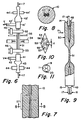
- Fig. 1 is a cross-sectional view of a capillary tube after optical fibers have been inserted therein.
- Fig. 2 is an oblique view of an apparatus for forming an antireflection termination on the end of an optical fiber.
- Fig. 3 is a block diagram illustration of a system for measuring the back-reflectance of an optical fiber.
- Figs. 4 and 5 are schematic illustrations of two steps during the operation of the apparatus of Fig. 2.
- Fig. 6 is a schematic illustration of an apparatus for collapsing a capillary tube and drawing the midregion thereof.
- Fig. 7 is a partial cross-sectional view illustrating the collapse of the glass tube around the fibers to form a solid midregion.
- Fig. 8 is a cross-sectional view through the solid midregion of Fig. 7 along lines 8-8.
- Fig. 9 is a partial cross-sectional illustration of a fiber optic coupler after it has been drawn down and sealed at its ends.
- Figs. 10 and 11 are schematic illustrations of aperture cross-sections having fibers disposed therein.
- a first embodiment pertains to an improved method of making 1x2 fiber optic couplers.
- This method employs a tube 10 (Fig. 1) having a longitudinal bore or aperture 11. Tapered apertures 12 and 13 form funnel-like entrances to aperture 11 at end surfaces 14 and 15, respectively.
- the softening point temperature of tube 10 should be lower than that of the fibers that are to be inserted therein.
- Suitable tube compositions are SiO 2 doped with 1 to 25 wt. % B 2 O 3 and SiO 2 doped with 0.1 to approximately 2.5 wt. % fluorine. Glasses comprising silica and combinations of these dopants can also be employed.
- Tube 10 can be formed by depositing glass particles on a cylindrical mandrel to form a porous, cylindrically-shaped preform.
- Apertures of non-circular cross-section can be formed in the tube by shrinking the tube onto a carbon mandrel of desired cross-section and then burning out the mandrel and stretching the tube to decrease its diameter.
- a short section of tube having tapered apertures 12 and 13 can be formed by attaching a capillary tube to a source of air pressure, and while rotating the tube, directing a flame onto the tube at spaced intervals. The pressure within the tube forms a bubble at each region softened by the flame. The tube is scored and severed at the center of each bubble.
- Coated fibers 17 and 18 comprise glass fibers 19 and 20, respectively, each comprising a core and a cladding and each having a protective coating 21 and 22, respectively. A portion of the coating intermediate the ends of coated fiber 17 is removed for a distance slightly longer than the length of aperture 11 but shorter than the length of tube 10.
- Table 29 is slidable in the x direction along grooves 28a of base 28.
- An oxygen-acetylene torch 24 is mounted on base member 28 so that it can be moved in the y and z directions. The position of torch 24 is initially adjusted in the z direction so nozzle 24′ lies approximately in the plane of the surface of table 29.
- Two closely spaced guides 30 are located at one end of table 29 in alignment with a fiber retaining groove (not shown). A fiber is held in the groove by retainer disk 36.
- Microscope 26 is mounted on table 29 in such a location that the end of a fiber extending beyond table 29 appears in its field of view.
- the coating is removed from the end of coated fiber 18.
- An oxygen-acetylene flame is directed at the uncoated fiber a short distance from the end thereof, and the end of the fiber is pulled until it becomes severed from the remainder of the fiber. As shown in Fig. 4, the fiber now has a tapered end.
- the end of coated fiber 20 remote from the tapered end is connected to the apparatus of Fig. 3 to monitor the reflectance from the tapered end.
- the system of Fig. 3 comprises a 2x2 3 dB coupler having ports 1-4.
- a laser is connected to port 1, and an optical power meter is connected to port 2.
- the end of the optical fiber that comprises port 3 is cleaved, and that end is immersed in a tube of index matching gel to prevent the reflection of light from the immersed end back through the coupler to the power meter.
- the end of fiber 20 remote from the tapered end is fusion spliced to port 4. Laser light which reflects from the tapered end of fiber 20 (and from the rounded end formed by the Fig. 2 apparatus) passes through the coupler to the power meter.
- Fiber 20 is placed between guides 30 such that it lies in the groove in the surface of table 29 with its tapered end extending beyond the table toward nozzle 24′.
- the end of the fiber is positioned in the center of the microscope field.
- torch 24 turned off and table 29 moved to the left of base 28 (as viewed in Fig. 2), the position of torch 24 is adjusted in the y direction such that the end of the fiber is adjacent nozzle 24′ (Fig. 4).
- Table 29 is moved to the right, and the torch is ignited. Only the bright, central portion 23 of the flame is illustrated in Figs. 4 and 5. Table 29 is moved slowly to the left, whereby the tapered tip of fiber 20 is heated by the flame.
- the tapered end is provided with a low reflectance termination by heating it to lower the viscosity of the material thereof by an amount sufficient to cause the material to recede back along the fiber and form a rounded endface 25 (Fig. 5), the final diameter of which is about equal to or slightly smaller than the original uncoated fiber diameter.
- the heating is continued until the power of the laser light that reflects from the rounded end and propagates back through the fiber toward the opposite end is less than a predetermined value.
- a current specification for the reflected power is -50 dB.
- the step of heating the tapered end be terminated before the diameter of the rounded endface becomes larger than the initial diameter of the uncoated fiber.
- fiber end 25 preferably does not extend beyond tube end 14; it may be located within tapered aperture 12 or in the end of longitudinal aperture 11.
- the fibers are wiped to eliminate residual material.
- a small amount of ethyl alcohol may be squirted into the tube to temporarily lubricate the fibers during insertion thereof; it then readily evaporates.
- Coated fiber 17 is inserted through aperture 11 until the uncoated section thereof is situated just beyond tube end 15.
- the uncoated portion of coated fiber 18 is held adjacent the uncoated portion of coated fiber 17, and both coated fibers are moved together toward tube end 14 until the coating end regions, which are adjacent one another, become wedged in tapered aperture 13.
- the uncoated portion of coated fiber 17 is then disposed intermediate end surfaces 14 and 15, the uncoated portion of coated fiber 17 preferably being centered within aperture 11. End 25 of fiber 18 is located between midregion 27 and end 14 of tube 10.
- the stripped portion of fiber 17 could initially be centered in aperture 11, and the stripped end portion of fiber 18 could thereafter be inserted into the aperture. However, the fiber insertion process is facilitated by simultaneously inserting both stripped portions.
- Vacuum attachment 41 which is shown in cross-section in Fig. 1, may comprise a tube 40, a collar 39 threaded thereon, and an O-ring 38 disposed between the collar and tube.
- Vacuum line 42 is connected to tube 40.
- One end of a length of thin rubber tubing 43 is attached to that end of vacuum attachment 41 that is opposite preform 31; the remaining end of the tubing extends between clamp jaws 44.
- Upper vacuum attachment 41′ is similarly associated with line 42′, tubing 43′ and clamp jaws 44′. The coated portions of the fibers extend from tubing 43 and 43′.
- Tube 10 can be secured by chucks 32 and 33 prior to the fiber insertion step. While tube 10 is supported vertically by the chucks, the fibers are inserted as described above. The fibers extending from both ends of the tube are threaded through their respective vacuum apparatus, and vacuum attachments 41 and 41′ are connected to the tube.
- Vacuum is applied to the lower portion of coupler preform 31 by clamping jaws 44 on tubing 43 while the upper vacuum attachment is vented to air or connected to a source of inert gas or a liquid cleaning agent. This washes from aperture 11 any loose debris which has accumulated therein during the fiber insertion step. Jaws 44′ are then clamped against tubing 43′ to apply vacuum to the upper portion of preform 31.
- the flame from ring burner 34 heats tube 10 for a short period of time, typically about 25 seconds, to increase the temperature of midregion 27 of the tube to the softening temperature thereof.
- the matrix glass collapses onto fibers 19 and 20 and urges them into mutual contact.
- the tube matrix glass surrounds the fibers and fills the aperture to form a solid structure as shown in Figs. 7 and 8.
- the longitudinal length of the collapsed region depends upon the temperature and time duration of the flame, the thermal conductivity of the glass tube, and the amount of vacuum applied.
- the flame is reignited, and the center of the collapsed region is reheated to the softening point of the materials thereof.
- the flame duration for the stretch process which depends upon the desired coupler characteristics, is usually between 10 and 20 seconds.
- the shorter heating period for the stretch step results in a stretched region that is shorter than the collapsed region. Stretching only the central portion of the collapsed midregion ensures that the coupling region of the fibers will be embedded in the matrix glass of the capillary tube.
- the fibers are also heated since they are completely surrounded by the matrix glass of the capillary tube and are therefore in thermal contact therewith.
- the flame is extinguished and stages 45 and 46 pull in opposite directions until the coupler length has been increased by a predetermined amount to bring the fiber cores closer together along a distance sufficient to accomplish a predetermined type of coupling.
- the diameter of midregion 27 is reduced as illustrated by region 51 of Fig. 9.
- the diameter of drawn down region 51 depends upon various fiber and operational parameters. The ratio of the drawn down diameter of region 51 to the starting diameter of midregion 27 (the draw down ratio) is determined by the optical characteristics of the particular device being made.
- draw down ratios are a function of the ratio of the signal split between the fibers, the refractive index difference between the tube and the fiber cladding, the outside diameter of the fiber cladding, the diameter of the fiber core, signal operating wavelength, cutoff wavelength, the tolerable excess loss, and the like.
- a preferred range of draw down ratios is between about 1/2 to 1/20; however, couplers can be made having draw down ratios outside this range.
- the amount of stretching to which the coupler preform must be subjected to achieve a given type of coupler is initially determined by injecting light energy into the input fiber of a coupler preform and monitoring the output power at the output fibers during the stretch operation.
- the predetermined ratio of the dynamic output powers from the two fibers can be used as an interrupt to cause stages 45 and 46 to stop pulling the sample.
- the apparatus can be programmed to move the stages that proper stretching distance during the fabrication of subsequent couplers that are to have said predetermined characteristics.
- the coupling characteristics of a coupler change as a newly formed coupler cools down. If the feedback system stops the stretching operation when 50% of the input power is coupled to each output fiber at 1300 nm, the coupling ratio at 1300 nm will not be 50/50 after the coupler cools down. The coupler is therefore monitored at a wavelength that is longer than the desired operating wavelength. If, for example, the output signals are split 50/50 at some wavelength such as 1400 nm at the end of the stretching operation when the coupler is still hot, a 50/50 split may be obtained at a desired operating wavelength such as 1300 nm after the coupler cools to room temperature. A wavelength of 1400 nm would therefore be employed to monitor that coupler output during the stretching operation.
- the vacuum lines are removed from the resultant coupler, and quantities 48 and 49 of glue are applied to the ends of the capillary tube (Fig. 9).
- Heat (arrow H) can be applied locally to the uncollapsed regions of the coupler to drive air from the aperture.
- the heat source is removed, and glue is drawn into the aperture and then cured.
- Glue 48 and 49 increases the pull strength of the fiber pigtails and produces a hermetic seal.
- the resultant fiber optic coupler 50 of Fig. 9 functions to couple a signal propagating in the sole optical fiber at end 14 to the two optical fibers extending from end 15. The coupler is then removed from the draw apparatus and can be packaged if additional stiffness is desired.
- Midregion 27 could be heated by means of a conventional single-flame burner during the tube collapse and stretch steps, in which case the capillary tube is preferably rotated with respect to the flame to provide uniform heating.
- the burner may traverse midregion 27 during the tube collapse step and/or the stretch step.
- the vacuum source could be attached to only one tube end, in which case a traversing burner should traverse the tube toward the evacuated end of the tube.
- stage 45 could be moved at a different velocity than stage 46 and in the same direction as stage 46.
- tube 10 can be disposed in any orientation including vertical and horizontal during the tube collapse and/or drawing operations.
- tube 10 be allowed to cool prior to being reheated for the stretch step.
- This temporal separation of the two steps results in better process control and therefore better reproducibility.
- Couplers can also be made by an alternative embodiment wherein the steps of collapsing the tube onto the fibers and drawing or stretching the midregion of the tube are performed in a single heating operation.
- this modified embodiment can result in a reduction in hermeticity, and it can adversely affect manufacturing reproducibility.
- the size of the tube aperture has been dictated by the diameter of the coating, since the fiber coating extended through the tapered apertures at both ends of the coupler and extended a short distance into the central aperture 53 as shown in Fig. 10.
- the tube aperture was preferably shaped like a diamond or the like so that the coated fibers would be properly positioned by the aperture.
- Coatings 54 and 55 fit snugly into aperture 53; optical fibers 56 and 57 were therefore held in proper alignment at both ends of the tube. Since the aperture cross-section was sufficiently large to accommodate the fiber coating, the fibers were spaced from the aperture walls, and they were separated from each other by a distance, d, which is equal to twice the coating thickness.
- the step of collapsing the tube onto the fibers may occur with less than optimal results, i.e. bubbles may form adjacent the fibers, or glass from the tube wall may enter the region between the fibers.
- bubbles may form adjacent the fibers, or glass from the tube wall may enter the region between the fibers.
- the tube collapse step is enhanced by employing a capillary tube having an aperture of reduced cross-sectional size.
- This improvement is made possible by that feature of the present method whereby the coated portion of only one fiber is passed through aperture 11, the remaining coated fiber or fibers being stripped at the ends thereof, and the stripped ends being inserted in the aperture in such a manner that they do not occupy any portion of the aperture that is occupied by coated fiber.
- Fig. 11 The absence of coatings in aperture 11 enables that aperture to be smaller in cross-section than aperture 53. Since the walls of aperture 11 undergo less inward movement before total collapse is achieved, and since fibers 19 and 20 must be moved a shorter distance to achieve mutual contact, the tube collapse step is more likely to be accomplished without matrix glass from the tube flowing between the fibers and without the deviation of the fibers from a linear path. Furthermore, because of the enhanced tube collapse step, the collapsed tube midregion is more likely to be free from air lines, bubbles, or the like. The process of the present invention should therefore more consistently produce couplers having low loss and predetermined coupling ratio. In addition, the use of preterminated fiber 20 allows the terminated end 25 to be located within glass tube 25. This eliminates the need to sever and terminate a leg after the coupler has been formed.
Landscapes
- Physics & Mathematics (AREA)
- General Physics & Mathematics (AREA)
- Optics & Photonics (AREA)
- Chemical & Material Sciences (AREA)
- Engineering & Computer Science (AREA)
- Materials Engineering (AREA)
- Organic Chemistry (AREA)
- Plasma & Fusion (AREA)
- Mechanical Coupling Of Light Guides (AREA)
- Optical Couplings Of Light Guides (AREA)
- Optical Fibers, Optical Fiber Cores, And Optical Fiber Bundles (AREA)
- Manufacture, Treatment Of Glass Fibers (AREA)
Claims (9)
- Un procédé pour réaliser un coupleur de fibres optiques en disposant deux fibres optiques (17, 18) de telle manière qu'une partie au moins de chaque fibre s'avance dans l'alésage continu (11) d'un tube en verre (10), au moins la partie de chaque fibre qui est située dans la région médiane (27) du tube ne portant pas de revêtement, et en étirant longitudinalement la portion centrale de ladite région médiane, le procédé étant caractériséen ce que ledit alésage de tube présente initialement une région de diamètre constant qui s'étend à travers ladite région moyenne, et une région conique (12, 13) entre chaque extrémité du tube et la région de diamètre constant,et en ce que l'opération de mise en position des fibres comprend les opérations consistant :à fournir une première fibre optique (17) portant un revêtement protecteur sauf en une section non revêtue située à distance de ses extrémités, à fournir une deuxième fibre optique (18) portant un revêtement protecteur sauf en une section non revêtue à l'une de ses extrémités, età insérer la section non revêtue de ladite première fibre dans ledit alésage de tube soit avant, soit simultanément à l'opération d'insertion de la section non revêtue de ladite deuxième fibre dans ledit alésage de tube, l'extrémité de la portion non revêtue de ladite deuxième fibre se terminant entre ladite région médiane et l'extrémité dudit tube,l'opération d'insertion de la section non revêtue de ladite première fibre dans ledit alésage de tube étant poursuivie jusqu'à ce que les portions revêtues desdites première et deuxième fibres se trouvent situées à l'extérieur de ladite portion de diamètre constant dudit alésage,et en ce que la région médiane du tube est chauffée et resserrée sur les fibres avant l'opération d'étirage de la portion centrale de la région médiane du tube,le diamètre de ladite région de diamètre constant étant inférieur à la somme des diamètres d'une section de fibre revêtue et d'une section de fibre non revêtue.
- Un procédé selon la revendication 1, dans lequel l'opération de fourniture d'une deuxième fibre optique (18) comprend la fourniture d'une fibre présentant une section non revêtue (20) à l'une de ses extrémités, ladite section non revêtue présentant une extrémité arrondie (25).
- Un procédé selon la revendication 1, dans lequel l'opération de fourniture d'une deuxième fibre optique (18) comprend la fourniture d'une fibre présentant une section non revêtue (20) à l'une de ses extrémités, la région terminale de ladite section non revêtue allant s'amincissant jusqu'à un diamètre inférieur à celui du reste de ladite section non revêtue, ladite deuxième fibre présentant une extrémité de forme sphérique relativement élargie (25) dont le diamètre n'est pas supérieur au diamètre de la partie non amincie de ladite fibre, ceci permettant de rendre relativement petit le diamètre de l'alésage du tube et d'améliorer ainsi ladite opération de resserrage dudit tube.
- Un procédé selon la revendication 1, dans lequel l'opération de fourniture d'une deuxième fibre optique comprend l'enlèvement du revêtement de l'extrémité d'une fibre revêtue (18) pour former une section terminale non revêtue (20), le chauffage de ladite section terminale non revêtue à distance de son extrémité et une traction de la fibre de chaque côté de la section chauffée pour rompre l'extrémité de ladite section terminale non revêtue, en laissant ainsi sur ladite deuxième fibre optique une section terminale amincie non revêtue, puis le chauffage de l'extrémité de ladite section amincie pour abaisser la viscosité de la matière dont elle est formée à un degré suffisant pour faire reculer la matière le long de la fibre et lui faire former une face terminale arrondie (25).
- Un procédé selon la revendication 4, dans lequel l'opération de fouorniture d'une deuxième fibre optique comprend en outre l'examen du facteur de réflexion de ladite face terminale arrondie (25) et la poursuite de l'opération de chauffage de l'extrémité de ladite section amincie jusqu'à ce que ledit facteur de réflexion se trouve réduit à une valeur prédéterminée.
- Un procédé selon la revendication 1, dans lequel l'opération de mise en place comprend le soutien dudit tube (10) dans une orientation verticale, l'enfilement de ladite première fibre (17) par ladite ouverture jusqu'à ce que sa section non revêtue (19) se situe au-dessous dudit tube, la retenue de la portion sommitale de ladite première fibre qui dépasse du sommet dudit tube, la mise en place de la section non revêtue (20) de ladite deuxième fibre (18) adjacente à la section non revêtue (19) de ladite première fibre, la traction de ladite portion sommitale de ladite première fibre pour amener sa section non revêtue dans ladite ouverture (11), et le déplacement simultané de ladite section non revêtue (20) de ladite deuxième fibre pour l'amener dans ledit tube.
- Un coupleur de fibres optiques comprenantun corps en verre de forme allongée (10) présentant une région médiane pleine et une première et une deuxième portions terminales opposées qui s'étendent respectivement de ladite région médiane à la première et à la deuxième extrémités (14, 15) dudit corps,un premier et un deuxième passages longitudinaux continus s'étendant respectivement de ladite première extrémité et de ladite deuxième extrémité dudit corps à sa région médiane, lesdits passages présentant une région de diamètre constant adjacente à ladite région médiane et une région conique adjacente auxdites extrémités de tube,une première fibre optique en verre (17) comportant un coeur et un gainage, ladite première fibre s'étendant à travers ledit corps et au-delà de la première et de la deuxième extrémités dudit corps, les portions de ladite première fibre qui dépassent dudit corps portant un revêtement protecteur, le revêtement protecteur de ladite première fibre se terminant à l'intérieur desdites régions coniques desdits passages,une deuxième fibre optique en verre (18) comportant un coeur et un gainage, l'une des extrémités de ladite deuxième fibre s'étendant au-delà de la première extrémité dudit corps, la deuxième extrémité de ladite deuxième fibre se terminant à l'intérieur de ladite deuxième portion terminale dudit corps, entre ladite région médiane et l'extrémité dudit corps, la portion de ladite deuxième fibre qui s'étend à l'intérieur de la région médiane pleine et de la deuxième portion terminale dudit corps étant non revêtue,la portion centrale de ladite région médiane ayant un diamètre plus petit que le diamètre du reste dudit corps en verre, les coeurs desdites fibres optiques étant plus proches l'un de l'autre dans la portion centrale de ladite région médiane que dans le reste dudit corps en verre, de manière à permettre à des signaux optiques d'être couplés du coeur de l'une desdites fibres au coeur de l'autre desdites fibres,le diamètre desdites régions de diamètre constant étant inférieur à la somme des diamètres d'une section de fibre revêtue et d'une section de fibre non revêtue,et des moyens (48, 49) dans lesdits premier et deuxième passages pour sceller audit corps toutes les fibres qui en sortent.
- Un coupleur de fibres optiques selon la revendication 7, dans lequel la deuxième extrémité (25) de ladite deuxième fibre se termine à l'intérieur dudit deuxième passage.
- Un coupleur de fibres optiques selon la revendication 8, dans lequel l'extrémité de ladite deuxième fibre (18) qui se termine à l'intérieur dudit deuxième passage présente une extrémité de forme sphérique (25), ladite extrémité de forme sphérique ayant un diamètre plus petit que le diamètre de la section de ladite deuxième fibre qui est située dans ledit premier passage, ladite extrémité de forme sphérique étant capable de rétroréfléchir dans ladite deuxième fibre moins de - 50 dB de la puissance qui se propage dans ladite fibre et arrive sur ladite extrémité de forme sphérique.
Priority Applications (1)
| Application Number | Priority Date | Filing Date | Title |
|---|---|---|---|
| EP96201257A EP0730171B1 (fr) | 1989-07-17 | 1990-07-04 | Méthode et dispositif pour fabriquer une terminaison pour une fibre optique avec faible réflectance |
Applications Claiming Priority (2)
| Application Number | Priority Date | Filing Date | Title |
|---|---|---|---|
| US380877 | 1989-07-17 | ||
| US07/380,877 US4979972A (en) | 1989-07-17 | 1989-07-17 | Method of making fiber optic couplers |
Related Child Applications (2)
| Application Number | Title | Priority Date | Filing Date |
|---|---|---|---|
| EP96201257A Division EP0730171B1 (fr) | 1989-07-17 | 1990-07-04 | Méthode et dispositif pour fabriquer une terminaison pour une fibre optique avec faible réflectance |
| EP96201257.1 Division-Into | 1990-07-04 |
Publications (3)
| Publication Number | Publication Date |
|---|---|
| EP0409447A2 EP0409447A2 (fr) | 1991-01-23 |
| EP0409447A3 EP0409447A3 (en) | 1992-01-02 |
| EP0409447B1 true EP0409447B1 (fr) | 1996-11-20 |
Family
ID=23502800
Family Applications (2)
| Application Number | Title | Priority Date | Filing Date |
|---|---|---|---|
| EP90307294A Expired - Lifetime EP0409447B1 (fr) | 1989-07-17 | 1990-07-04 | Méthode de fabrication d'un coupleur de fibres optiques |
| EP96201257A Expired - Lifetime EP0730171B1 (fr) | 1989-07-17 | 1990-07-04 | Méthode et dispositif pour fabriquer une terminaison pour une fibre optique avec faible réflectance |
Family Applications After (1)
| Application Number | Title | Priority Date | Filing Date |
|---|---|---|---|
| EP96201257A Expired - Lifetime EP0730171B1 (fr) | 1989-07-17 | 1990-07-04 | Méthode et dispositif pour fabriquer une terminaison pour une fibre optique avec faible réflectance |
Country Status (8)
| Country | Link |
|---|---|
| US (1) | US4979972A (fr) |
| EP (2) | EP0409447B1 (fr) |
| JP (1) | JP2665389B2 (fr) |
| KR (1) | KR0168651B1 (fr) |
| AU (1) | AU627598B2 (fr) |
| CA (1) | CA2006346C (fr) |
| DE (2) | DE69033798T2 (fr) |
| ES (1) | ES2097135T3 (fr) |
Cited By (3)
| Publication number | Priority date | Publication date | Assignee | Title |
|---|---|---|---|---|
| US6519388B1 (en) | 1998-12-04 | 2003-02-11 | Cidra Corporation | Tube-encased fiber grating |
| US6810178B2 (en) | 1998-12-04 | 2004-10-26 | Cidra Corporation | Large diameter optical waveguide having blazed grating therein |
| US6996316B2 (en) | 1999-09-20 | 2006-02-07 | Cidra Corporation | Large diameter D-shaped optical waveguide and coupler |
Families Citing this family (32)
| Publication number | Priority date | Publication date | Assignee | Title |
|---|---|---|---|---|
| US5179603A (en) * | 1991-03-18 | 1993-01-12 | Corning Incorporated | Optical fiber amplifier and coupler |
| US5346521A (en) * | 1991-04-11 | 1994-09-13 | Industrial Technology Research Institute | Apparatus and method for fabricating optical fiber coupler |
| US5203898A (en) * | 1991-12-16 | 1993-04-20 | Corning Incorporated | Method of making fluorine/boron doped silica tubes |
| US5255336A (en) * | 1992-04-20 | 1993-10-19 | Hoechst Celanese Corp. | Injection molded optical coupling elements |
| US5268979A (en) * | 1992-07-15 | 1993-12-07 | Corning Incorporated | Achromatic overclad fiber optic coupler |
| US5240489A (en) * | 1992-09-11 | 1993-08-31 | Corning Incorporated | Method of making a fiber optic coupler |
| US5251277A (en) * | 1992-09-11 | 1993-10-05 | Corning Incorporated | Optical fiber coupler exhibiting reduced polarization sensitivity and method of making same |
| US5268014A (en) * | 1992-11-05 | 1993-12-07 | Corning Incorporated | Method of making robust fiber optic coupler |
| US5263103A (en) * | 1992-11-16 | 1993-11-16 | At&T Bell Laboratories | Apparatus comprising a low reflection optical fiber termination |
| WO1994016346A1 (fr) * | 1993-01-15 | 1994-07-21 | Alexandr Alexandrovich Balagur | Convertisseur de mesure de pression, de difference de pression et d'ecoulement a fibres optiques, et procede de production de son element de detection |
| US5522003A (en) | 1993-03-02 | 1996-05-28 | Ward; Robert M. | Glass preform with deep radial gradient layer and method of manufacturing same |
| DE69330563T2 (de) * | 1993-11-08 | 2002-06-27 | Corning Inc | Kopplung von planaren optischen Wellenleitern und optischen Fasern mit geringer Rückreflexion |
| TW291539B (fr) | 1994-09-30 | 1996-11-21 | Corning Inc | |
| CA2184220A1 (fr) * | 1995-09-29 | 1997-03-30 | Joel Patrick Carberry | Appareil servant au micropositionnement de fibres optiques et methode connexe |
| EP0852572A4 (fr) * | 1995-09-29 | 2002-12-04 | Corning Inc | Procede et dispositif de fabrication d'un coupleur a fibres optiques |
| US5889908A (en) * | 1997-07-31 | 1999-03-30 | Corning Incorporated | 1xN fiber optic coupler/splitter |
| WO2000037914A2 (fr) | 1998-12-04 | 2000-06-29 | Cidra Corporation | Sonde manometrique a reseau de bragg |
| CN1153054C (zh) | 1998-12-04 | 2004-06-09 | 塞德拉公司 | 布拉格光栅压力传感器 |
| DE69942749D1 (de) | 1998-12-04 | 2010-10-21 | Cidra Corp | Spannungsisolierter temperatursensor mit einem bragg-gitter |
| US6982996B1 (en) | 1999-12-06 | 2006-01-03 | Weatherford/Lamb, Inc. | Large diameter optical waveguide, grating, and laser |
| US6439055B1 (en) | 1999-11-15 | 2002-08-27 | Weatherford/Lamb, Inc. | Pressure sensor assembly structure to insulate a pressure sensing device from harsh environments |
| US6626043B1 (en) | 2000-01-31 | 2003-09-30 | Weatherford/Lamb, Inc. | Fluid diffusion resistant glass-encased fiber optic sensor |
| US6827508B2 (en) * | 2001-05-24 | 2004-12-07 | Fiber Optic Network Solutions Corporation | Optical fiber fusion system |
| KR100442168B1 (ko) * | 2002-01-14 | 2004-07-30 | (주)에스엘테크놀로지 | 광섬유 커플러 제조장치 |
| US6701057B2 (en) * | 2002-05-21 | 2004-03-02 | Corning Incorporated | Method and apparatus for separating two optical fibers |
| US6959131B2 (en) * | 2002-11-15 | 2005-10-25 | Charles Stark Draper Laboratory, Inc. | Achromatic fiber-optic power splitter and related methods |
| US9366821B2 (en) * | 2012-03-02 | 2016-06-14 | Tyco Electronics Corporation | Method of forming fused coupler |
| US20130236153A1 (en) * | 2012-03-06 | 2013-09-12 | The Royal Institution For The Advancement Of Learning / Mcgill University | Method of manufacturing optical fibers, tapered optical fibers and devices thereof |
| TW201430415A (zh) * | 2013-01-22 | 2014-08-01 | Hon Hai Prec Ind Co Ltd | 光纖耦合連接器 |
| DE102015118010A1 (de) * | 2015-08-31 | 2017-03-02 | Fraunhofer-Gesellschaft zur Förderung der angewandten Forschung e.V. | Herstellung eines Faserkopplers |
| CA3148286A1 (fr) * | 2019-08-21 | 2021-02-25 | Universite Laval | Procede de couplage de fibres optiques et coupleur optique |
| KR102333205B1 (ko) * | 2019-10-30 | 2021-11-30 | 주식회사 이상테크 | 반사광 모니터링 장치 및 이를 포함하는 레이저 빔 결합기 |
Family Cites Families (26)
| Publication number | Priority date | Publication date | Assignee | Title |
|---|---|---|---|---|
| GB1252126A (fr) * | 1967-11-08 | 1971-11-03 | ||
| DE2812346A1 (de) * | 1977-03-23 | 1978-09-28 | Tokyo Shibaura Electric Co | Lichtverteiler |
| US4291940A (en) * | 1977-06-13 | 1981-09-29 | Canadian Patents & Development Ltd. | Low loss access coupler for multimode optical fiber distribution systems |
| FR2430025A1 (fr) * | 1978-06-29 | 1980-01-25 | Lemesle Marcel | Coupleur a fibres optiques |
| JPS55146409A (en) * | 1979-05-02 | 1980-11-14 | Sumitomo Electric Ind Ltd | Photo coupling device |
| CA1123642A (fr) * | 1979-07-04 | 1982-05-18 | Alexander W. Lightstone | Connecteur multimode pour fibres optiques |
| EP0022374B1 (fr) * | 1979-07-09 | 1983-04-06 | The Post Office | Procédé pour positionner précisément l'extrémite d'un guide d'ondes optiques diélectriques dans un dispositif de couplage de guide d'ondes optiques |
| CA1118621A (fr) * | 1979-11-01 | 1982-02-23 | Lawrence C. Smyth | Methode et gabarit de fabrication de raccords pour fibres optiques |
| JPS5692503A (en) * | 1979-12-27 | 1981-07-27 | Nec Corp | Nonreflection terminator of optical fiber |
| JPS56126817A (en) * | 1980-03-11 | 1981-10-05 | Sharp Corp | Working method of optical fiber end lens |
| DE3035089A1 (de) * | 1980-09-17 | 1982-04-22 | Siemens AG, 1000 Berlin und 8000 München | Verfahren zur herstellung von verteiler- und mischerelementen fuer die optische nachrichtentechnik und verfahren zur herstellung einer fuer das erstgenannte verfahren notwendigen vorform |
| US4377403A (en) * | 1980-09-29 | 1983-03-22 | The United States Of America As Represented By The Secretary Of The Navy | Method of fabricating a fused single-mode fiber bidirectional coupler |
| AU544705B2 (en) * | 1981-08-17 | 1985-06-13 | Australian Telecommunications Commission | Tap coupler for optical fibres |
| US4426215A (en) * | 1981-10-07 | 1984-01-17 | International Telephone And Telegraph Corporation | Method of fabricating a low loss fused biconical taper fiber optic coupler |
| US4490163A (en) * | 1982-03-22 | 1984-12-25 | U.S. Philips Corporation | Method of manufacturing a fiber-optical coupling element |
| DE3224518A1 (de) * | 1982-07-01 | 1984-01-05 | Standard Elektrik Lorenz Ag, 7000 Stuttgart | Optischer koppler |
| JPS59195615A (ja) * | 1983-04-21 | 1984-11-06 | Sumitomo Electric Ind Ltd | 光フアイバ分岐の製造方法 |
| GB2150703B (en) * | 1983-11-30 | 1987-03-11 | Standard Telephones Cables Ltd | Single mode fibre directional coupler |
| DE3407820A1 (de) * | 1984-03-02 | 1985-11-07 | Siemens AG, 1000 Berlin und 8000 München | Verfahren zur herstellung eines fasertapers mit brechender linse |
| AU569803B2 (en) * | 1984-09-06 | 1988-02-18 | Hitachi Limited | Optical fibre star coupler |
| JPH0721568B2 (ja) * | 1985-04-01 | 1995-03-08 | 株式会社日立製作所 | 光フアイバカプラ |
| US4927222A (en) * | 1986-06-16 | 1990-05-22 | Shiley Incorporated | Dual optical fiber device |
| JPS63217314A (ja) * | 1987-03-06 | 1988-09-09 | Nippon Telegr & Teleph Corp <Ntt> | 光分岐器の製造方法 |
| US4763272A (en) * | 1987-03-29 | 1988-08-09 | The United States Of America As Represented By The Secretary Of The Navy | Automated and computer controlled precision method of fused elongated optical fiber coupler fabrication |
| US4931076A (en) * | 1987-08-07 | 1990-06-05 | Corning Incorporated | Method of making fiber optic coupler |
| JPH02166408A (ja) * | 1988-11-22 | 1990-06-27 | Itt Corp | 光ファイバを先細にする装置と方法 |
-
1989
- 1989-07-17 US US07/380,877 patent/US4979972A/en not_active Expired - Lifetime
- 1989-12-21 CA CA002006346A patent/CA2006346C/fr not_active Expired - Fee Related
-
1990
- 1990-07-04 EP EP90307294A patent/EP0409447B1/fr not_active Expired - Lifetime
- 1990-07-04 DE DE69033798T patent/DE69033798T2/de not_active Expired - Fee Related
- 1990-07-04 EP EP96201257A patent/EP0730171B1/fr not_active Expired - Lifetime
- 1990-07-04 DE DE69029175T patent/DE69029175T2/de not_active Expired - Fee Related
- 1990-07-04 ES ES90307294T patent/ES2097135T3/es not_active Expired - Lifetime
- 1990-07-09 AU AU58810/90A patent/AU627598B2/en not_active Ceased
- 1990-07-12 KR KR1019900010589A patent/KR0168651B1/ko not_active IP Right Cessation
- 1990-07-16 JP JP2185470A patent/JP2665389B2/ja not_active Expired - Fee Related
Non-Patent Citations (1)
| Title |
|---|
| PATENT ABSTRACTS OF JAPAN vol. 13, no. 9 (P-811)(3357), 11 January 1988 & JP-A-63 217 314 * |
Cited By (3)
| Publication number | Priority date | Publication date | Assignee | Title |
|---|---|---|---|---|
| US6519388B1 (en) | 1998-12-04 | 2003-02-11 | Cidra Corporation | Tube-encased fiber grating |
| US6810178B2 (en) | 1998-12-04 | 2004-10-26 | Cidra Corporation | Large diameter optical waveguide having blazed grating therein |
| US6996316B2 (en) | 1999-09-20 | 2006-02-07 | Cidra Corporation | Large diameter D-shaped optical waveguide and coupler |
Also Published As
| Publication number | Publication date |
|---|---|
| EP0409447A3 (en) | 1992-01-02 |
| DE69029175T2 (de) | 1997-05-22 |
| AU5881090A (en) | 1991-01-17 |
| EP0730171A3 (fr) | 1996-10-09 |
| KR910003413A (ko) | 1991-02-27 |
| DE69029175D1 (de) | 1997-01-02 |
| EP0409447A2 (fr) | 1991-01-23 |
| US4979972A (en) | 1990-12-25 |
| ES2097135T3 (es) | 1997-04-01 |
| CA2006346C (fr) | 2001-10-23 |
| DE69033798T2 (de) | 2002-05-29 |
| DE69033798D1 (de) | 2001-10-18 |
| EP0730171B1 (fr) | 2001-09-12 |
| JPH0351807A (ja) | 1991-03-06 |
| EP0730171A2 (fr) | 1996-09-04 |
| JP2665389B2 (ja) | 1997-10-22 |
| KR0168651B1 (ko) | 1999-04-15 |
| AU627598B2 (en) | 1992-08-27 |
| CA2006346A1 (fr) | 1991-01-17 |
Similar Documents
| Publication | Publication Date | Title |
|---|---|---|
| EP0409447B1 (fr) | Méthode de fabrication d'un coupleur de fibres optiques | |
| EP0431311B1 (fr) | Coupleur à fibre optique achromatique et son procédé de fabrication | |
| EP0578982B1 (fr) | Coupleur à fibres optiques achtomatique et revêtu | |
| US5131735A (en) | Fiber optic coupler | |
| US5295210A (en) | Optical waveguide fiber achromatic coupler | |
| EP0432421B1 (fr) | Composant optique dopé en chlorine | |
| US4902324A (en) | Method of reproducibly making fiber optic coupler | |
| US5339372A (en) | Low loss coupler | |
| US5009692A (en) | Method of making fiber optic coupler | |
| US5754720A (en) | Low loss fiber optic coupler and method | |
| EP0588043B1 (fr) | Coupleur à sensibilité de polarisation réduite | |
| US4983195A (en) | Method of making fiber optic coupler with longitudinal protrusions | |
| US5031300A (en) | Method of making optical devices | |
| US5104434A (en) | Method of making fiber optic couplers |
Legal Events
| Date | Code | Title | Description |
|---|---|---|---|
| PUAI | Public reference made under article 153(3) epc to a published international application that has entered the european phase |
Free format text: ORIGINAL CODE: 0009012 |
|
| AK | Designated contracting states |
Kind code of ref document: A2 Designated state(s): DE ES FR GB IT NL |
|
| RHK1 | Main classification (correction) |
Ipc: G02B 6/28 |
|
| PUAL | Search report despatched |
Free format text: ORIGINAL CODE: 0009013 |
|
| AK | Designated contracting states |
Kind code of ref document: A3 Designated state(s): DE ES FR GB IT NL |
|
| 17P | Request for examination filed |
Effective date: 19920605 |
|
| 17Q | First examination report despatched |
Effective date: 19931227 |
|
| GRAG | Despatch of communication of intention to grant |
Free format text: ORIGINAL CODE: EPIDOS AGRA |
|
| GRAH | Despatch of communication of intention to grant a patent |
Free format text: ORIGINAL CODE: EPIDOS IGRA |
|
| GRAH | Despatch of communication of intention to grant a patent |
Free format text: ORIGINAL CODE: EPIDOS IGRA |
|
| GRAA | (expected) grant |
Free format text: ORIGINAL CODE: 0009210 |
|
| AK | Designated contracting states |
Kind code of ref document: B1 Designated state(s): DE ES FR GB IT NL |
|
| DX | Miscellaneous (deleted) | ||
| REF | Corresponds to: |
Ref document number: 69029175 Country of ref document: DE Date of ref document: 19970102 |
|
| ITF | It: translation for a ep patent filed |
Owner name: ING. A. GIAMBROCONO & C. S.R.L. |
|
| ET | Fr: translation filed | ||
| REG | Reference to a national code |
Ref country code: ES Ref legal event code: FG2A Ref document number: 2097135 Country of ref document: ES Kind code of ref document: T3 |
|
| ET | Fr: translation filed |
Free format text: CORRECTIONS |
|
| PLBE | No opposition filed within time limit |
Free format text: ORIGINAL CODE: 0009261 |
|
| STAA | Information on the status of an ep patent application or granted ep patent |
Free format text: STATUS: NO OPPOSITION FILED WITHIN TIME LIMIT |
|
| 26N | No opposition filed | ||
| PGFP | Annual fee paid to national office [announced via postgrant information from national office to epo] |
Ref country code: NL Payment date: 20010618 Year of fee payment: 12 |
|
| PGFP | Annual fee paid to national office [announced via postgrant information from national office to epo] |
Ref country code: ES Payment date: 20010716 Year of fee payment: 12 |
|
| REG | Reference to a national code |
Ref country code: GB Ref legal event code: IF02 |
|
| PG25 | Lapsed in a contracting state [announced via postgrant information from national office to epo] |
Ref country code: ES Free format text: LAPSE BECAUSE OF NON-PAYMENT OF DUE FEES Effective date: 20020705 |
|
| PG25 | Lapsed in a contracting state [announced via postgrant information from national office to epo] |
Ref country code: NL Free format text: LAPSE BECAUSE OF NON-PAYMENT OF DUE FEES Effective date: 20030201 |
|
| NLV4 | Nl: lapsed or anulled due to non-payment of the annual fee |
Effective date: 20030201 |
|
| REG | Reference to a national code |
Ref country code: ES Ref legal event code: FD2A Effective date: 20030811 |
|
| PGFP | Annual fee paid to national office [announced via postgrant information from national office to epo] |
Ref country code: FR Payment date: 20060717 Year of fee payment: 17 |
|
| PGFP | Annual fee paid to national office [announced via postgrant information from national office to epo] |
Ref country code: GB Payment date: 20060726 Year of fee payment: 17 |
|
| PGFP | Annual fee paid to national office [announced via postgrant information from national office to epo] |
Ref country code: IT Payment date: 20060731 Year of fee payment: 17 |
|
| PGFP | Annual fee paid to national office [announced via postgrant information from national office to epo] |
Ref country code: DE Payment date: 20060831 Year of fee payment: 17 |
|
| GBPC | Gb: european patent ceased through non-payment of renewal fee |
Effective date: 20070704 |
|
| PG25 | Lapsed in a contracting state [announced via postgrant information from national office to epo] |
Ref country code: DE Free format text: LAPSE BECAUSE OF NON-PAYMENT OF DUE FEES Effective date: 20080201 |
|
| PG25 | Lapsed in a contracting state [announced via postgrant information from national office to epo] |
Ref country code: GB Free format text: LAPSE BECAUSE OF NON-PAYMENT OF DUE FEES Effective date: 20070704 |
|
| REG | Reference to a national code |
Ref country code: FR Ref legal event code: ST Effective date: 20080331 |
|
| PG25 | Lapsed in a contracting state [announced via postgrant information from national office to epo] |
Ref country code: FR Free format text: LAPSE BECAUSE OF NON-PAYMENT OF DUE FEES Effective date: 20070731 |
|
| PG25 | Lapsed in a contracting state [announced via postgrant information from national office to epo] |
Ref country code: IT Free format text: LAPSE BECAUSE OF NON-PAYMENT OF DUE FEES Effective date: 20070704 |