EP0411265A1 - Drainage set for ureter drainage - Google Patents
Drainage set for ureter drainage Download PDFInfo
- Publication number
- EP0411265A1 EP0411265A1 EP90110165A EP90110165A EP0411265A1 EP 0411265 A1 EP0411265 A1 EP 0411265A1 EP 90110165 A EP90110165 A EP 90110165A EP 90110165 A EP90110165 A EP 90110165A EP 0411265 A1 EP0411265 A1 EP 0411265A1
- Authority
- EP
- European Patent Office
- Prior art keywords
- drainage
- thickening
- rail
- set according
- guide
- Prior art date
- Legal status (The legal status is an assumption and is not a legal conclusion. Google has not performed a legal analysis and makes no representation as to the accuracy of the status listed.)
- Granted
Links
- HJNUDFCUJGFWIC-UHFFFAOYSA-N C1C2C1CSC2 Chemical compound C1C2C1CSC2 HJNUDFCUJGFWIC-UHFFFAOYSA-N 0.000 description 1
Images

Classifications
-
- A—HUMAN NECESSITIES
- A61—MEDICAL OR VETERINARY SCIENCE; HYGIENE
- A61M—DEVICES FOR INTRODUCING MEDIA INTO, OR ONTO, THE BODY; DEVICES FOR TRANSDUCING BODY MEDIA OR FOR TAKING MEDIA FROM THE BODY; DEVICES FOR PRODUCING OR ENDING SLEEP OR STUPOR
- A61M27/00—Drainage appliance for wounds or the like, i.e. wound drains, implanted drains
- A61M27/002—Implant devices for drainage of body fluids from one part of the body to another
- A61M27/008—Implant devices for drainage of body fluids from one part of the body to another pre-shaped, for use in the urethral or ureteral tract
Definitions
- the proximal end 36 of the rail 3 is placed on the guide mandrel 4 from the distal end 42 to approximately half of the ver Thickness 41 pushed on, as can be seen in Figure 8.
- the distal end 51 of the slider 5 is pushed onto the guide stylet 4 from the proximal end 48 up to half of the thickening 41 and the coming together of the end faces 36 and 51 of the rail 3 and the slider 5.
Landscapes
- Health & Medical Sciences (AREA)
- Urology & Nephrology (AREA)
- Ophthalmology & Optometry (AREA)
- Otolaryngology (AREA)
- Engineering & Computer Science (AREA)
- Anesthesiology (AREA)
- Biomedical Technology (AREA)
- Heart & Thoracic Surgery (AREA)
- Hematology (AREA)
- Life Sciences & Earth Sciences (AREA)
- Animal Behavior & Ethology (AREA)
- General Health & Medical Sciences (AREA)
- Public Health (AREA)
- Veterinary Medicine (AREA)
- Media Introduction/Drainage Providing Device (AREA)
- Prostheses (AREA)
- External Artificial Organs (AREA)
- Sink And Installation For Waste Water (AREA)
- Addition Polymer Or Copolymer, Post-Treatments, Or Chemical Modifications (AREA)
Abstract
Description
Die Erfindung betrifft ein Drainage-Set, insbesondere zur Ureter-Drainage, mit einer Drainage-Schiene, einem Führungsmandrin und einem Schieber.The invention relates to a drainage set, in particular for ureter drainage, with a drainage rail, a guide stylet and a slide.
Im Rahmen der Erfindung werden als Drainage-Schienen solche wie Ureter-Schienen, Katheter oder dergleichen verstanden, die aus relativ flexiblem Material, wie Kunststoff oder Silikon bestehen. Die Drainage-Schienen haben die Form eines zumindest einen gestreckten Abschnitt aufweisenden, flexiblen langen Hohlkörpers mit in der Mantelwandung angeordneten Drainageöffnungen und sind zumindestens proximal stirnseitig offen. Führungsdrähte bestehen vorzugsweise aus Metall, wie Edelstahl, und sind als Wendel mit einem axialen Hohlraum ausgebildet. Schieber sind Rohre, vorzugsweise Kunststoffrohre und besitzen insbesondere eine hinreichende axiale Steifigkeit. Es ist bekannt, im Körper verbleibende Ureter-Schienen in den Harnleiter einzusetzen, um bei Verengungen, Fisteln oder dergleichen den Abfluß aus der Niere sicherzustellen. Zur Festlegung der Schiene wurden Dislokationssicherungen in Form von Widerhaken am Außenumfang des Schienenkörpers oder aber Krümmungen oder hakenartige Ausbildungen der Schiene selbst an einem oder beiden ihrer Enden vorgesehen (Pig-Tail-Katheter). Die Schienen konnten derart eingeführt werden, daß entweder zunächst ein Führungsmandrin in den Ureter eingeführt wird und anschließend die Schiene über diesen in den Katheter eingeschoben wird oder aber alternativ hierzu die Schiene nur mit einem offenen Ende (dem proximalen Ende) versehen ist, während das distale Ende geschlossen ist. In diesem Fall wurde die Schiene über den Führungsmandrin geschoben, der aufgrund seiner relativen Steifheit das oder die Hakenenden streckt, so daß die Schiene dann mit eingeführtem Führungsmandrin und unter Vorschieben desselben gelegt werden konnte. Nachteilig ist in beiden Fällen, daß eine angulare Ausrichtung der Schiene nicht möglich ist. Führungsmandrin und Schiene sind relativ zueinander verdrehbar. Auch kann in gestrecktem Zustand ohne besondere Markierungen an der Schiene, wie röntgen- oder ultraschallsichtbare Markierungen, die Ausrichtung der Schiene vor Herausnehmen des Führungsmandrins nicht, mit Markierungen nur schlecht, festgestellt werden. Ein weiterer Nachteil der unter Vorschieben des Führungsmandrins eingeführten Schiene besteht darin, daß aufgrund der geschlossenen distalen Stirnseite die Drainage nicht so optimal ist, wie sie sein könnte und bei offener Stirnseite ist.In the context of the invention, drainage splints are understood to be those such as ureter splints, catheters or the like, which are made of relatively flexible material, such as plastic or silicone. The drainage rails have the shape of a flexible long hollow body having at least one stretched section with drainage openings arranged in the jacket wall and are at least proximally open on the end face. Guide wires are preferably made of metal, such as stainless steel, and are designed as a helix with an axial cavity. Slides are pipes, preferably plastic pipes and in particular have sufficient axial rigidity. It is known to insert ureteral splints remaining in the body into the ureter to ensure drainage from the kidney in the event of constrictions, fistulas or the like. To secure the splint, dislocation safeguards in the form of barbs on the outer circumference of the splint body or curvatures or hook-like configurations of the splint itself were provided at one or both of its ends (pig-tail catheter). The splints could be inserted in such a way that either a guide stylet is first inserted into the ureter and then the splint is inserted into the catheter via this, or alternatively the splint is only provided with one open end (the proximal end) while the distal end End is closed. In this case, the rail was pushed over the guide stylet, which because of its relative stiffness stretches the hook end (s), so that the rail could then be placed with the guide stylet inserted and with the same being pushed forward. A disadvantage in both cases is that angular alignment of the rail is not possible. The guide stylet and the rail can be rotated relative to one another. Also, in the stretched state without special markings on the rail, such as X-ray or ultrasound-visible markings, the orientation of the rail before removing the guide stylet cannot be determined, with markings only poorly. Another disadvantage of the splint inserted under advancement of the guide mandrel is that due to the closed distal end face, the drainage is not as optimal as it could be and is with the end face open.
Aus der DE-OS 35 11 448 ist ein hohler Führungsmandrin für Drainageschienen bekanntgeworden, der ein offenes distales Ende aufweist und in seinem Mantel achsparallel ein- oder mehrfach gespalten ist. Durch den Mandrin ragt ein Draht, der fest mit einem aus dem distalen Ende des Mandrin herausragenden Keil verbunden ist. Der Keil ist durch den Draht in den Mandrin hereinziehbar, so daß er das Ende des Mandrins aufweitet, wodurch dieses zur Anlage an der Innenwand der Drainageschiene gelangen kann. Hierdurch ist zwar theoretisch auch ein Zurückziehen und Verdrehen der Drainageschiene im Ureter möglich, es bestehen aber Bedenken hinsichtlich der praktischen Verwirklichbarkeit, da der Keil, wenn er in den Ureter hereingezogen ist, mit erheblicher Kraft kraftschlüssig in diesem festsitzt und Bedenken bestehen, daß er durch den mit ihm verbundenen dünnen Draht entgegen diesem Kraftschluß aus dem Führungsmandrin ausgeschoben werden kann, wenn man bedenkt, daß ein solcher Mandrin einen Innendurchmesser im Bereich von wenigen Zehntelmillimetern aufweist, aber eine Länge von bis zu 1 m; der mit dem Keil verbundene Draht dürfte nicht mit einer ausreichenden axialen Steifigkeit erhaltbar sein. Darüberhinaus kann diese Ausgestaltung die Abbiegung des distalen Endes der Drainageschiene nicht zwischen verschiedenen Winkeln kontinuierlich steuern. Auch ist das Steuern und Legen von distal offenen Schienen zur optimalen Drainage nicht möglich, da das offene distale Ende des Führungsmandrins und die Kanten der Schlitze Verletzungsgefahren bedingen.From DE-OS 35 11 448 a hollow guide stylet for drainage splints has become known, which has an open distal end and in or parallel to its jacket is split several times. A wire extends through the stylet and is firmly connected to a wedge protruding from the distal end of the stylet. The wedge can be pulled into the stylet through the wire, so that it widens the end of the stylet, whereby this can come to rest against the inner wall of the drainage rail. In this way, it is theoretically also possible to retract and twist the drainage rail in the ureter, but there are concerns regarding the practical feasibility, since the wedge, when it has been drawn into the ureter, sticks forcefully in the ureter and there are concerns that it will the thin wire connected to it can be pushed out of the guide stylet against this adhesion, if one considers that such a stylet has an inner diameter in the range of a few tenths of a millimeter, but a length of up to 1 m; the wire connected to the wedge should not be obtainable with sufficient axial rigidity. Furthermore, this configuration cannot continuously control the bending of the distal end of the drainage rail between different angles. It is also not possible to control and place distally open splints for optimal drainage, since the open distal end of the guide stylet and the edges of the slots pose a risk of injury.
Der Erfindung liegt daher die Aufgabe zugrunde, ein Drainage-Set zu schaffen, das bei einfachster Ausgestaltung eine optimale Steuerung der Schiene hinsichtlich ihrer angularen Ausrichtung, aber auch ein einfaches Zurückziehen und gegebenenfalls Entfernen der Schiene - unter Freigabe derselben - und insbesondere das Legen von distal offenen Schienen mit optimalen Drainagen ermöglicht.The invention is therefore based on the object of providing a drainage set which, with the simplest design, provides optimal control of the splint with regard to its angular orientation, but also simple retraction and, if appropriate, removal of the splint - with the same being released - and, in particular, distal placement open rails with optimal drainage.
Erfindungsgemäß wird die genannte Aufgabe durch ein Drainage-Set gelöst, welches dadurch gekennzeichnet ist, daß der Führungsmandrin eine fest auf ihm ausgebildete Verdickung aufweist, auf der die Drainage-Schiene mit ihrem Lumen reibschlüssig aufschiebbar ist, und daß der Lumendurchmesser des Schiebers größer oder gleich dem Durchmesser der Verdickung, aber geringer als der Außendurchmesser der Drainage-Schiene ist.According to the invention, the above-mentioned object is achieved by a drainage set, which is characterized in that the guide stylet has a thickening firmly formed on it, on which the drainage rail with its lumen can be slid on, and in that the lumen diameter of the slider is greater or equal the diameter of the thickening, but less than the outer diameter of the drainage rail.
Die Erfindung schafft die Möglichkeit zur radialen kraftschlüssigen Verspannung des in die Schiene eingeführten Führungsmandrins bzw. eines Führungsmandrinabschnitts und der Schiene.The invention creates the possibility of radial non-positive clamping of the guide stylet or a guide stylet section and the rail inserted into the rail.
Das erfindungsgemäße Drainage-Set wird derart eingesetzt, daß zunächst die Schiene mit ihrem proximalen Ende vom distalen Ende des Führungsmandrines über diesen geschoben wird, bis ihr proximales Ende zur Verdickung gelangt. Das proximale Ende der Schiene wird dann kraftschlüssig über die Verdickung des Führungsmandrines geschoben und derart kraftschlüssig axial und angular relativ fest mit dem Führungsmandrin verbunden. Hierdurch werden aufgrund der Steifigkeit des Führungsmandrines die Enden der Drainage-Schiene gestreckt, so daß diese mittels des Führungsmandrines durch ein Zystoskop in den Ureter und durch diesen geschoben werden kann. Jetzt oder auch vorher wird vom proximalen Ende des Führungsmandrines her über diesen ein Schieber geschoben, der unter Gegenhaltung mit seinem distalen Ende am proximalen Ende der Schiene angreift und diese von der Verdickung des Führungsmandrines herunterschieben kann. Dabei ist es wichtig, daß der Innendurchmesser des Schiebers und der Querschnitt der Verdickung angepaßt sind, so daß die Verdickung axial im Schieber verschiebbar ist. Der Führungsmandrin kann anschließend herausgezogen werden, wodurch die Biegekräfte der Enden der Drainage-Schiene freigegeben werden, so daß sich die Ursprungshaken derselben wieder bilden können, die Dislokationssicherungen der Drainage-Schiene, wie bei einer Ureter-Schiene in der Niere und in der Uretra, bilden. Aufgrund der angularen und axialen kraftschlüssigen Verbindung zwischen Verdickung des Führungsmandrines und Drainage-Schiene kann letztere nicht nur eingeschoben, sondern auch zurückgeschoben und mittels des Führungsmandrines angular verdreht werden. Letzteres ist insbesondere vorteilhaft, wenn der Führungsmandrin hohl ausgebildet ist und sich durch ihn eine axial relativ verschiebbare Seele erstreckt, wobei insbesondere die Seele proximal mit einem Handhabungsansatz fest verbunden ist, der eine der Schiene entsprechende Stärke aufweist und die Seitenelastizität des Führungsmandrins in seinem distalen Endbereich bei aus diesem Bereich herausgezogener Seele geringer ist als die Rückstellkraft des hakenförmigen distalen Endes der Drainage-Schiene. Hierdurch kann durch Zurückziehen der Seele im Führungsmandrin die Steifigkeit des distalen Endes desselben reduziert werden, so daß aufgrund der seitlichen Eigenbiegekräfte der Drainage-Schiene deren distales Ende und das distale Ende des Führungsmandrines leicht zur Seite geneigt werden, so daß das Drainage-Set mit der Schiene durch Verdrehen des Führungsmandrines um ein Hindernis herumgesteuert werden kann.The drainage set according to the invention is used in such a way that first the proximal end of the splint is pushed over the distal end of the guide mandrel over the latter until its proximal end becomes thickened. The proximal end of the splint is then pushed non-positively over the thickening of the guiding mandrel and is thus relatively firmly connected axially and angularly to the guiding mandrel. As a result, the ends of the drainage splint are stretched due to the rigidity of the guide mandrel, so that it can be pushed into and through the ureter by means of the guide mandrel through a cystoscope. Now or even before, a slide is pushed from the proximal end of the guide mandrel over it, which engages with its distal end against the proximal end of the rail and can push it down from the thickening of the guide mandrel. It is important that the inside diameter of the slider and the cross-section of the thickening are adapted so that the thickening is axially displaceable in the slider. The guide stylet can then be pulled out, causing the bending forces of the ends of the drainage splint are released so that the original hooks of the same can form again, which form the dislocation safeguards of the drainage splint, as in the case of a ureter splint in the kidney and in the uretra. Due to the angular and axial non-positive connection between the thickening of the guide mandrel and the drainage splint, the latter can not only be pushed in, but also pushed back and rotated angularly by means of the guide mandrel. The latter is particularly advantageous if the guide stylet is hollow and an axially relatively displaceable core extends through it, the core in particular being firmly connected proximally to a handling attachment which has a thickness corresponding to the rail and the side elasticity of the guide stylet in its distal end region when the core is pulled out of this area is less than the restoring force of the hook-shaped distal end of the drainage splint. As a result, the stiffness of the distal end of the same can be reduced by withdrawing the core in the guide mandrel, so that due to the lateral inherent bending forces of the drainage splint, the distal end and the distal end of the guide mandrel are slightly inclined to the side, so that the drainage set with the Rail can be steered around an obstacle by twisting the guide stylet.
Bei einer Ausgestaltung in der Art, daß die Verdickung eine endlich-zählige Rotationsachse parallel der Längsachse des Führungsmandrins aufweist ode daß die Verdickung einen mehrkantigen Querschnitt aufweist, wird ein besonders drehfester Reibschluß zwischen der Verdickung und der Drainage-Schiene gewährleistet. Somit wird der angulare Reibschluß zwischen der Verdickung und der Drainage-Schiene erheblich gesteigert. Zudem hat es sich in Verbindung mit den beiden vorgenannten Ausführungen als sehr vorteilhaft erwiesen, wenn der Schieber so ausgebildet ist, daß die Kontur des lichten Querschnitts des Schiebers an seinem distalen Ende der Kontur der Verdickung angepaßt ist, so daß eine in das distale Ende des Schiebers eingesteckte Verdickung zwar axial verschieblich aber drehfest mit diesem verbunden ist. Dadurch ist es möglich, die Verdickung mit dem Schieber zu verdrehen, wenn die Verdickung zumindest teilweise in das distale Ende des Schiebers eingesteckt ist.In a configuration such that the thickening has a finite rotation axis parallel to the longitudinal axis of the guide mandrel or that the thickening has a polygonal cross section, a particularly rotationally fixed frictional engagement between the thickening and the drainage rail is ensured. Thus, the angular friction between the thickening and the drainage rail is increased considerably. In addition, it has proven to be very advantageous in connection with the two aforementioned designs proved if the slider is designed so that the contour of the clear cross section of the slider is adapted at its distal end to the contour of the thickening, so that a thickening inserted into the distal end of the slider is connected to the latter axially displaceably but non-rotatably. This makes it possible to twist the thickening with the slider if the thickening is at least partially inserted into the distal end of the slider.
Mit dieser Ausbildung ist es also möglich, eine drehfeste Verbindung des Schiebers mit der Drainage-Schiene herzustellen. Daraus ergibt sich der Vorteil, daß der Führungsmandrin nicht so drehfest und dementsprechend dünner ausgebildet sein kann.With this training it is therefore possible to produce a rotationally fixed connection of the slide with the drainage rail. This has the advantage that the guide stylet cannot be designed to be non-rotatable and accordingly thinner.
Weitere bevorzugte Ausgestaltungen sehen vor, daß die Verdickung aus einer am Führungsmandrin befestigten, diesen umgebenden Hülse besteht, wobei entweder vorgesehen sein kann, daß die Verdickung einstückig mit dem Führungsmandrin ausgebildet ist oder daß die Verdickung durch Kleben mit dem Führungsmandrin verbunden ist oder aber daß die Verdickung durch Anschmelzen und anschließendem Erstarren mit dem Führungsmandrin verbunden ist.Further preferred embodiments provide that the thickening consists of a sleeve attached to the guiding stylet and surrounding it, whereby it can either be provided that the thickening is formed in one piece with the guiding stylet or that the thickening is connected to the guiding stylet by gluing or else that Thickening by melting and subsequent solidification is connected to the guide stylet.
Andere bevorzugte Merkmale sind darin zu sehen, daß die Verdickung an ihren Stirnseiten sich konisch verjüngt, daß die Drainage-Schiene im unbelasteten Zustand zumindestens ein, vorzugsweise zwei gekrümmte Ende(n) aufweist und/oder insbesondere daß die Drainage-Schiene ein stirnseitig offenes distales Ende aufweist.Other preferred features can be seen in the fact that the thickening tapers conically on its end faces, that the drainage rail has at least one, preferably two curved end (s) in the unloaded state and / or in particular that the drainage rail has a distal end that is open at the end End.
Weitere Vorteile und Merkmale der Erfindung ergeben sich aus den Ansprüchen und aus der nachfolgenden Beschreibung, in der bevorzugte Ausführungsformen der Erfindung unter Bezugnahme auf die Zeichnung im einzelnen erläutert sind. Dabei zeigt:
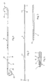
- Figur 1 Eine Drainage-Schiene als Teil des erfindungsgemäßen Drainage-Sets;
- Figur 2 ein erfindungsgemäß ausgebildeter Führungsmandrin als Teil des Drainage-Sets;
Figur 3 einen Schieber des erfindungsgemäßen Drainage-Sets;Figur 4 eine vergrößerte Ausschnittsdarstellung des erfindungsgemäßen Drainage-Sets bei auf die Verdickung aufgeschobener Drainage-Schiene mit angesetztem Schieber;Figur 5 Führungsmandrin mit aufgeschobener Ureter-Schiene bei eingeschobener Seele;- Figur 6 den Gegenstand der
Figur 5 bei zurückgezogener Seele; - Figur 7 eine Ausschnittdarstellung des proximalen Endes einer proximal offenen Ureter-Schiene mit aus dessen offenem Ende herausragenden proximalen Ende des Führungsmandrins;
- Figur 8 wie
Figur 4 jedoch verbindet die Verdickung die Drainage-Schiene und den Schieber; - Figur 9 Schnitt von Figur 8 und
- Figur 10 ein weiterer Querschnitt der Verdickung.
- 1 shows a drainage rail as part of the drainage set according to the invention;
- FIG. 2 shows a guide stylet designed according to the invention as part of the drainage set;
- Figure 3 shows a slide of the drainage set according to the invention;
- FIG. 4 shows an enlarged sectional view of the drainage set according to the invention with the drainage rail pushed onto the thickening with the slide attached;
- FIG. 5 guiding stylet with pushed-on ureter splint with inserted soul;
- Figure 6 shows the subject of Figure 5 with the soul withdrawn;
- FIG. 7 shows a detail of the proximal end of a proximally open ureter splint with the proximal end of the guide stylet protruding from its open end;
- FIG. 8 like FIG. 4, however, the thickening connects the drainage rail and the slide;
- Figure 9 section of Figure 8 and
- Figure 10 shows another cross section of the thickening.
Das erfindungsgemäße Drainage-Set weist eine Drainage-Schiene 3, einen Führungsdraht als Führungsmandrin 4 - in Form eines eng gewickelten Spiraldrahtes - und einen Schieber 5 auf.The drainage set according to the invention has a
Die Drainage-Schiene, wie Ureter-Schiene kann zystoskopisch, perkutan oder intraoperativ eingesetzt werden. Eine solche Ureter-Schiene ist an sich bekannt, wobei sie aus einem langgestreckten Hauptteil 31 besteht, das an seinem distalen Ende 34 und seinem proximalen Ende 36 mit einem Bogen oder Haken 32,33 versehen ist. Im Bereich der beiden Haken 32,33 sind in der seitlichen Wandung zum inneren Hohlraum führende Drainage-Öffnungen 37 ausgebildet. Ebenfalls könnten am langgestreckten Hauptteil 31 Drainage-Öffnungen ausgebildet sein. Weiterhin kann eine solche Schiene umlaufende Rillen oder Erhebungen 35 aufweisen, die über die Länge hin in verschiedener Anzahl gruppiert sind. Während bekannte Ureter-Schienen zumindestens an einem Ende, nämlich dem distalen Ende, vollständig geschlossen sind und sein müssen, damit sie durch einen eingeführten Führungsmandrin eingeschoben werden können und während eine solche, an sich bekannte Ureterschiene ebenfalls bei der Erfindung verwendet werden kann und Teil des erfindungsgemäßen Drainage-Sets sein kann, sieht eine äußerst bevorzugte Ausgestaltung vor, daß die Schiene an beiden Stirnseiten offen ist. Hierdurch wird der herstellungsmäßige Vorteil erreicht, daß die Schiene 3 vom Endlosschlauchmaterial abgeschnitten werden kann, ohne daß ein Ende in einem separaten Schnitt noch verschlossen werden muß. Darüberhinaus liegt ein weiterer wesentlicher Vorteil in der besseren Drainage- Wirkung durch eine distale stirnseitige Öffnung des Hohlraums der Schiene 3.The drainage splints, such as ureter splints, can be used cystoscopically, percutaneously or intraoperatively. Such a ureteral splint is known per se, wherein it consists of an elongated
Der Führungsmandrin 4 weist eine Verdickung 41 auf. Die Verdickung 41 ist vorzugsweise etwa 1 cm lang und weist einen Durchmesser auf, der etwas über dem Durchmesser des Lumens der Ureter-Schiene 3 liegt, so daß diese auf die Verdickung 41 mit ihrem proximalen Ende 36 kraftschlüssig aufschiebbar ist. Der Durchmesser der Verdickung kann dabei von 1 bis 2 mm je nach Stärke der Schiene 3 liegen. Die Verdickung 41 befindet sich vom distalen Ende 42 des Mandrins 4 in einem Abstand, der im wesentlichen der Länge der Schiene 3 entspricht und bei geschlossener Schiene etwas unterhalb der Länge derselben, bei offener Schiene etwas oberhalb, beispielsweise 1 cm oberhalb der Länge der Schiene 3, liegt.The
Die Verdickung 41 ist fest mit dem Mandrin 4 verbunden. Die Verdickung 41 kann einstückig mit dem Mandrin 4 ausgebildet sein. Im dargestellten Ausführungsbeispiel besteht sie aus einer über den Mandrin 4 geschobenen Hülse, die mit diesem fest verklebt ist. Stattdessen könnte eine Kunststoffhülse auch nach Aufschieben bis auf den gewünschten Ort auf dem Führungsmandrin 4 durch Erwärmen und Aufschmelzen mit diesem ohne Klebstoff fest verbunden sein. Die Verbindung kann in diesem Falle vorzugsweise dadurch vorgenommen werden, daß der Mandrin 4 und damit die die Verdickung 41 bildende Hülse von innen her erhitzt wird, beispielsweise durch resistive oder induktive Erhitzung des als Draht ausgebildeten Mandrins 4.The thickening 41 is firmly connected to the
Der Mandrin 4 ist vorzugsweise hohl ausgebildet, beispielsweise als in an sich bekannter Weise gewickelte Drahtwendel, die axial durch einen zumindestens an ihren beiden Enden festgelegten Flachdraht zusammengehalten wird. Das distale Ende 42 ist abgerundet, beispielsweise mit einer Kuppe 43 versehen. Durch den durch die Wendel des Führungsmandrins 4 gebildeten Hohlraum erstreckt sich frei bzw. reibschlüssig eine Seele 44, die am proximalen Ende 46 des Mandrins 4 mit einem Handhabungsansatz 47 fest verbunden ist, der die gleiche Stärke wie der eigentliche Führungsmandrin 4 aufweist. Mittels des Ansatzes 47 kann die Seele 44 im Führungsmandrin 4 relativ zu diesem axial verschoben werden. Der Sinn dieser Ausgestaltung wird weiter unten erläutert. Weiter gehört zum erfindungsgemäßen Drainage-Set ein Schieber 5 (Figur 3). Es handelt sich hierbei um ein Kunststoffhohlrohr, das an beiden Enden offen ist. Der Innendurchmesser des Schiebers 5 ist größer als der Durchmesser der Verdickung 41, so daß der Schieber 5 frei ohne Reibung über die Verdickung 41 gleiten kann. Der Innendurchmesser des Schiebers 5 ist aber geringer als der Außendurchmesser der Schiene 3, so daß der Schieber 5 stirnseitig an der Schiene 3 angreifen und die Schiene 3 mittels des Schiebers verschoben werden kann.The
Während in den Figuren 1 bis 3 die einzelnen Teile des erfindungsgemäßen Drainage-Sets separat dargestellt sind, zeigt die Figur 4 eine Ausschnittsdarstellung des zum Einsatz zusammengesetzten Drainage-Sets. Hierbei ist die Schiene 3 vom distalen Ende 43 des Führungsmandrins 4 her über diesen bis zur Verdickung 41 und über diese geschoben. Die Verdickung 41 ist an ihren Stirnseiten konisch ausgebildet. Da der Durchmesser der Verdickung 41 leicht über dem Innendurchmesser des Lumens der Schiene 3 liegt, sitzt diese kraftschlüssig auf der Verdickung 41 auf. Die beiden Hakenausbildungen 32,33 der Schiene 3 sind dabei durch die Eigensteifigkeit des Führungsmandrins 4 (gegebenenfalls aufgrund voll in diesen eingeschobener Seele 44) gestreckt oder aufgestellt, so daß die Schiene 3 eine gerade gestreckte Form aufweist, wie sie in der Figur 5 dargestellt ist. In diesem Zustand kann die Schiene durch ein Zystoskop in den zu drainierenden Hohlraum, wie den Ureter, eingeschoben werden. Um die Schiene 3 von der Verdickung 41 und damit vom Mandrin 4 zu lösen, so daß dieser nach Legen der Schiene zurückgezogen werden kann, wird der Schieber 5 über den Mandrin 4 (von dessen proximalem Ende 48 her) verschoben, bis seine distale Stirnseite 51 zur Anlage an der proximalen Stirnseite 36 der Schiene 3 gelangt. Bei weiterem Vorschieben des Schiebers 5 unter Gegenhaltung des Führungsmandrins 4 am proximalen Ende 48 (Figur 2) kann die Schiene 3 von der Verdickung 41 durch die Stirnseite 51 des Schiebers 5 abgeschoben werden oder der Schieber 5 wird gegengehalten und der Führungsmandrin 4 mit seiner Verdickung 41 wird zurückgezogen, wobei der Schieber 5 ein Zurückziehen der Drainage-Schiene 3 verhindert. Hierdurch wird der Kraft- oder Reibschluß zwischen Schiene 3 und der Verdickung 41 des Führungsmandrins 4 gelöst. Anschließend kann der Führungsmandrin 4 frei, gegebenenfalls durch den Schieber 5, aus dem Körperhohlraum herausgezogen werden.While the individual parts of the drainage set according to the invention are shown separately in FIGS. 1 to 3, FIG. 4 shows a detail of the drainage set assembled for use. Here, the
Beim Einschieben des Führungsmandrins 4 in die Schiene 3 von deren proximalen Ende 36 her wird der Führungsmandrin bis in den Bereich des distalen Hakens oder der Krümmung 32 am distalen Ende 34 eingeschoben, wobei der Führungsmandrin 4 aufgrund seiner Eigensteifigkeit, wie gesagt, den Haken 32 in an sich bekannter Weise aufstellt, so daß dann das distale Ende 34 der Schiene die zum Einführen erforderliche wesentlich gestreckte Ausgestaltung aufweist (Figur 5).When the
Die Verdickung kommt dadurch zur Anlage an der Innenwandung der Schiene 3 im Bereich des gestreckten Teils 31, beult diese leicht aus, schafft insgesamt aber eine gut reib- bzw. kraftschlüssige Verbindung mit der Innenwandung der Schiene 3. Hiernach kann die Schiene 3 dann gelegt werden, indem sie mittels des Führungsmandrins 4 beispielsweise durch die Harnröhre, die Blase, in den Harnleiter und durch diesen hindurch mit ihrem distalen Ende 34 bis zur Niere geführt wird. Dies kann unter Beobachtung, wie unter Ultraschall- oder Röntgen-Beobachtung, erfolgen. Die Position der Schiene 3 kann wiederholt korrigiert werden. Insbesondere kann sie aufgrund der reibschlüssigen Verbindung zwischen der Verdickung 41 und damit der Einführvorrichtung und der Innenwandung der Schiene 3 nicht nur vorgeschoben, sondern auch zurückgezogen werden, um die Lage zu verbessern. Auch kann durch die reibschlüssige Verbindung die Schiene 3 verdreht werden, was beim Stand der Technik ebenfalls nicht möglich war. Der Reibschluß bezüglich des relativen Verdrehens der Verdickung 41 und der Schiene 3 wird dadurch erhöht, daß die Verdickung 41 mehrkantig ausgebildet ist. Eine bevorzugte Ausführung sieht vor, daß die Verdickung einen quadratischen Querschnitt aufweist (vergleiche Figur 9).The thickening thereby comes to rest on the inner wall of the
Wenn die Schiene 3 ihre richtige Position erreicht hat, so wird die Schiene 3 in der beschriebenen Weise mittels des Schiebers 5 von der Verdickung 41 des Führungsmandrins 4 ab gestreift. Anschließend kann der Führungsmandrin 4 aus der Schiene 3 frei zurückgezogen werden.When the
Wenn die Schiene 3 beim Einschieben in den Körperhohlraum, wie den Ureter, mit ihrem distalen Ende 34 an ein Hindernis, wie eine Stenose oder dergleichen anstößt, um das sie herumgeführt werden muß, so kann, wie oben erläutert, die den Führungsmandrin 4 aussteifende Seele 44 über den Griffansatz 47 in proximale Richtung relativ zum Mandarin 4 zurückgezogen werden. Hierdurch wird das distale Ende 42 des Mandrins 4 weicher und setzt damit der die Hakenform 32,34 anstrebenden Eigenelastizität der Schiene 3 weniger Widerstand entgegen, so daß das distale Ende 34 der Schiene 3 in der aus der Figur 6 ersichtlichen Form leicht zur Seite gebogen werden kann. Weiterhin kann aufgrund der reibschlüssigen Verbindung zwischen Schiene 3 und Führungsmandrin 4 (über die Verdickung 41) die Schiene 3 durch Verdrehen des Führungsmandrins 4 ebenfalls mit verdreht werden, so daß das leicht abgebogene distale Ende 34 (Figur 6) hierdurch angular ausgerichtet werden kann. Es kann daher eine solche angulare Ausrichtung vorgenommen werden, daß das abgebogene distale Ende 34 an dem Hindernis, wie einer Stenose, vorbeizeigt, so daß beim weiteren Einschieben das distale Ende 34 die Schiene 3 um das Hindernis bzw. an diesem vorbeiführen kann. Dies ist ein wesentlicher Vorteil gegenüber dem bekannten Drainage-Set, das mittels Pusher-Technik eingeführt wird, bei dem der Führungsmandrin mit seinem distalen Ende an der distalen Innenwandung der Schiene anliegt (damit er sie derart schieben kann) und Schiene und Führungsmandrin relativ zueinander verdrehbar sind, während bei dem erfindungsgemäßen Drainage-Set Schiene und Führungsmandrin durch die kraftschlüssige Verbindung über die Verdickung 41 nicht nur axial, sondern auch angular zueinander festgelegt sind.As explained above, if the
Es kann vorkommen, daß Hindernisse, wie Stenosen, beispielsweise im Harnleiter, diesen so verschließen, daß das relativ breite distale Ende 34 der Schiene 3 sich durch den Verschluß keinen Weg schaffen kann. In diesem Falle ist es sinnvoll, eine Führungsschiene 3 mit einem stirnseitig offenen distalen Ende 34 zu verwenden und den Führungsmandrin 4 in und durch die Schiene 3 so weit hindurchzuschieben, daß das distale Ende 42 des Führungsmandrins 4 ein Stück aus dem distalen Ende 34 der Schiene 3 hinausragt, wie dies in Figur 7 dargestellt ist. Hierdurch wird eine gegenüber dem distalen Ende 34 der Schiene 3 wesentlich verjüngte Spitze des gesamten Drainage-Sets geschaffen (die durch die Kuppe 43 abgerundet ist). Hierdurch kann bei Verengung, beispielsweise Stenosen oder dergleichen, leichter ein Weg an dieser vorbei gefunden werden, da sich das gegenüber dem distalen Ende 34 der Schiene 3 dünnere distale Ende 42 des Führungsmandrins 4 leichter einen Weg durch die Verengung bahnen kann. Verletzungen werden durch die abgerundete Kuppe 43 des Führungsmandrins 4 vermieden. Eine solche distal offene Schiene 3 zeigt aufgrund des offenen distalen Endes 34 im übrigen eine verbesserte Drainagewirkung.It may happen that obstacles such as stenoses, for example in the ureter, close it so that the relatively wide
Das Herumsteuern der Schiene 3 um ein Hindernis wird im übrigen dadurch vereinfacht, daß bei der Abbiegung des distalen Endes 34 der Schiene 3 dieses unter Ultraschall deutlich erkennbar ist, während bei gestreckter Ausbildung der Haken 32,33 bei Einführen in herkömmlicher Weise diese nicht ohne weiteres unter Ultraschall erkennbar sind.Steering around the
In einer weiteren bevorzugten Ausführung ist vorgesehen, daß die Verdickung 41 und das distale Ende 51 des Schiebers 5 so ausgebildet sind, daß diese im eingesteckten Zustand drehfest zusammenwirken. Es wird dadurch, wie in Figur 8 dargestellt, eine drehfeste Verbindung des Schiebers 5 mit der Schiene 3 über die Verdickung 41, die als Kuppelglied wirkt, ermöglicht. Dazu ist es notwendig, daß die Verdickung 41 zum einen den entsprechenden Querschnitt, um mit dem distalen Ende 51 des Schiebers 5 zusammenwirken zu können, und zum anderen die entsprechende Länge aufweist, um gleichzeitig einen ausreichenden Reibschluß mit der Schiene 3 und die drehfeste Verbindung mit dem Schieber 5 zu gewährleisten.In a further preferred embodiment it is provided that the thickening 41 and the
Um die Möglichkeit auszunutzen, die Schiene 3 mit dem im Gegensatz zum Führungsmandrin 4 wesentlich torsionsstabileren Schieber 5 angular zu verdrehen, wird die Schiene 3 mit ihrem proximalen Ende 36 auf den Führungsmandrin 4 vom distalen Ende 42 her bis etwa zur Hälfte der Ver dickung 41 aufgeschoben, wie in Figur 8 zu sehen ist. Das distale Ende 51 des Schiebers 5 wird auf den Führungsmandrin 4 vom proximalen Ende 48 her bis zur Hälfte der Verdickung 41 und dem Zusammenkommen der Stirnseiten 36 und 51 der Schiene 3 und des Schiebers 5 aufgeschoben. Mit dem so vorbereiteten Drainage-Set kann dann die Schiene 3 optimal plaziert werden, wobei die Schiene 3 mit dem Schieber 5 vorwärts und dem Führungsmandrin zurück bewegt wird, das Verdrehen der Schiene 3 über den Schieber 5 und das Lösen der Schiene 3 durch eine axiale Relativ-Bewegung des Führungsmandrins 4 gegen den Schieber 5 erfolgt, wobei der Schieber 5 auf Druck und der Führungsmandrin auf Zug belastet wird. Dabei bewirkt der Druck des Schiebers 5 auf die Ureter-Schiene 3 deren Aufweitung, so daß sich der Reibschluß zwischen der Schiene 3 und der Verdickung 41 verringert, so daß ein Lösen der Verdickung 41 von der Schiene 3 erleichtert und das Herausziehen des Führungsmandrins 4 aus der Schiene 3 ermöglicht wird.In order to take advantage of the possibility of angularly rotating the
Figur 9 zeigt das drehfeste Zusammenwirken der Verdickung 41 mit dem distalen Ende 51 des Schiebers 5 gemäß der zuletzt beschriebenen vorzugsweisen Ausführung, wobei diese Darstellung jedoch keine Einschränkung auf diesen Querschnitt darstellen soll.FIG. 9 shows the rotationally fixed interaction of the thickening 41 with the
Figur 10 zeigt deshalb als Beispiel einen denkbaren Querschnitt der Verdickung 41. In dieser Ausführung weist die Verdickung 41 eine zweizählige Rotationssymmetrie bezüglich ihrer Längsachse auf.FIG. 10 therefore shows, as an example, a conceivable cross section of the thickening 41. In this embodiment, the thickening 41 has two-fold rotational symmetry with respect to its longitudinal axis.
Die Ureter-Schiene kann Längen von 16 bis 32 cm aufweisen, wobei die Verdickung 41, wie gesagt, vom distalen Ende 42 des Führungsmandrins 4 jeweils einen Abstand aufweist, im wesentlichen der der Länge der entsprechenden Drainage- Schiene 3 (mit den oben genannten Besonderheiten hinsichtlich distal geschlossener bzw. offener Schiene und/oder drehfester Verbindung Schieber/Verdickung) entspricht. Die Länge der Verdickung 41 kann vorzugsweise 0,5 bis 2 cm aufweisen und ihre Dicke im Bereich 1 bis 2 mm liegen. Der Führungsmandrin selbst hat eine Stärke von weniger als 1 mm, seine Gesamtlänge kann in weiten Bereichen variiert werden, beispielsweise zwischen 0,5 und 1 m. Beim offenem distalen Ende 34 der Schiene 3 ragen vorzugsweise wenige mm bis 1 cm aus der Schiene 3 heraus. Die sonstigen Dimensionen sind übliche und an sich bekannt.The ureteral splint can have lengths of 16 to 32 cm, the thickening 41, as mentioned, being at a distance from the
Claims (14)
Priority Applications (1)
| Application Number | Priority Date | Filing Date | Title |
|---|---|---|---|
| AT90110165T ATE93153T1 (en) | 1989-07-29 | 1990-05-29 | DRAINAGE SET FOR URETERAL DRAINAGE. |
Applications Claiming Priority (2)
| Application Number | Priority Date | Filing Date | Title |
|---|---|---|---|
| DE3925263A DE3925263A1 (en) | 1989-07-29 | 1989-07-29 | DRAINAGE SET FOR URETER DRAINAGE |
| DE3925263 | 1989-07-29 |
Publications (2)
| Publication Number | Publication Date |
|---|---|
| EP0411265A1 true EP0411265A1 (en) | 1991-02-06 |
| EP0411265B1 EP0411265B1 (en) | 1993-08-18 |
Family
ID=6386189
Family Applications (1)
| Application Number | Title | Priority Date | Filing Date |
|---|---|---|---|
| EP90110165A Expired - Lifetime EP0411265B1 (en) | 1989-07-29 | 1990-05-29 | Drainage set for ureter drainage |
Country Status (5)
| Country | Link |
|---|---|
| EP (1) | EP0411265B1 (en) |
| AT (1) | ATE93153T1 (en) |
| DE (2) | DE3925263A1 (en) |
| ES (1) | ES2044314T3 (en) |
| HK (1) | HK1007521A1 (en) |
Cited By (2)
| Publication number | Priority date | Publication date | Assignee | Title |
|---|---|---|---|---|
| WO1996041652A1 (en) * | 1995-06-13 | 1996-12-27 | Cogent Light Technologies, Inc. | Illuminating ureteral catheter and method of placement |
| EP0752251A2 (en) * | 1995-07-06 | 1997-01-08 | Uromed Kurt Drews Gmbh | Urologic drainage device with urethral catheter |
Families Citing this family (1)
| Publication number | Priority date | Publication date | Assignee | Title |
|---|---|---|---|---|
| DE10155767B4 (en) * | 2001-11-14 | 2004-07-15 | Walter, Thomas, Dr. | ureter |
Citations (3)
| Publication number | Priority date | Publication date | Assignee | Title |
|---|---|---|---|---|
| US2024982A (en) * | 1934-12-19 | 1935-12-17 | Harry C Scott | Surgical instrument |
| FR2557460A1 (en) * | 1984-01-03 | 1985-07-05 | Bristol Myers Co | URETRAL DRAIN AND EQUIPMENT FOR BRIDGING OBSTRUCTIONS IN THE URETRE COMPRISING SUCH A DRAIN |
| EP0313807A1 (en) * | 1987-09-21 | 1989-05-03 | Advanced Cardiovascular Systems, Inc. | Extendable guidewire for vascular procedures |
-
1989
- 1989-07-29 DE DE3925263A patent/DE3925263A1/en not_active Withdrawn
-
1990
- 1990-05-29 EP EP90110165A patent/EP0411265B1/en not_active Expired - Lifetime
- 1990-05-29 AT AT90110165T patent/ATE93153T1/en not_active IP Right Cessation
- 1990-05-29 DE DE9090110165T patent/DE59002377D1/en not_active Expired - Fee Related
- 1990-05-29 ES ES90110165T patent/ES2044314T3/en not_active Expired - Lifetime
-
1998
- 1998-06-25 HK HK98106666A patent/HK1007521A1/en not_active IP Right Cessation
Patent Citations (3)
| Publication number | Priority date | Publication date | Assignee | Title |
|---|---|---|---|---|
| US2024982A (en) * | 1934-12-19 | 1935-12-17 | Harry C Scott | Surgical instrument |
| FR2557460A1 (en) * | 1984-01-03 | 1985-07-05 | Bristol Myers Co | URETRAL DRAIN AND EQUIPMENT FOR BRIDGING OBSTRUCTIONS IN THE URETRE COMPRISING SUCH A DRAIN |
| EP0313807A1 (en) * | 1987-09-21 | 1989-05-03 | Advanced Cardiovascular Systems, Inc. | Extendable guidewire for vascular procedures |
Cited By (4)
| Publication number | Priority date | Publication date | Assignee | Title |
|---|---|---|---|---|
| WO1996041652A1 (en) * | 1995-06-13 | 1996-12-27 | Cogent Light Technologies, Inc. | Illuminating ureteral catheter and method of placement |
| US5954652A (en) * | 1995-06-13 | 1999-09-21 | Cogent Light Technologies, Inc. | Slipover illuminating ureteral catheter and method of installation |
| EP0752251A2 (en) * | 1995-07-06 | 1997-01-08 | Uromed Kurt Drews Gmbh | Urologic drainage device with urethral catheter |
| EP0752251A3 (en) * | 1995-07-06 | 1997-06-25 | Drews Kurt Uromed Gmbh | Urologic drainage device with urethral catheter |
Also Published As
| Publication number | Publication date |
|---|---|
| DE59002377D1 (en) | 1993-09-23 |
| DE3925263A1 (en) | 1991-01-31 |
| HK1007521A1 (en) | 1999-04-16 |
| ATE93153T1 (en) | 1993-09-15 |
| ES2044314T3 (en) | 1994-01-01 |
| EP0411265B1 (en) | 1993-08-18 |
Similar Documents
| Publication | Publication Date | Title |
|---|---|---|
| EP0366870B1 (en) | Ureteral catheter with a clamp connection onto an advancing tube | |
| DE3831652C2 (en) | ||
| EP0593948B1 (en) | Stent-set | |
| EP0348692B1 (en) | Device for entering a vein or artery by means of a guide wire | |
| EP1893272B1 (en) | Insertion aid for percutaneous tracheostomy | |
| DE3900738C2 (en) | ||
| DE60311414T2 (en) | CATHETER WITH SHAPED RAMP FOR GUIDING WIRE | |
| DE69726147T2 (en) | GUIDE WIRE FEEDER AND METHOD | |
| DE3937531C2 (en) | Dilatation catheter assembly | |
| DE102011009482B4 (en) | Safety cannula | |
| DE8513185U1 (en) | Endotube | |
| DE19916060A1 (en) | Stent device | |
| DE2218901B2 (en) | Operating instrument insertion trocar - comprises thin strip wound in spiral round sleeve and fixed to sleeve | |
| EP0529341B1 (en) | Set of instruments for anaesthesia | |
| EP1559379A1 (en) | Instrument for placing tissue markers | |
| DE4102427C2 (en) | Obturator as an insertion aid for a medical endoscope | |
| DE4113703C2 (en) | Guide catheter with pre-bent end area | |
| DE3444219C2 (en) | Device for intermittent self-catheterization | |
| EP0411265B1 (en) | Drainage set for ureter drainage | |
| DE4129237A1 (en) | TROCAR SLEEVE | |
| DE3446940A1 (en) | URETARY GUIDE CATHETER | |
| DE4103573A1 (en) | Catheter for removing obstructions from urine duct - consists of tube made of plastics material with curved inner end | |
| EP1782745B1 (en) | Tissue marker comprising a preformed wire with a distal slit | |
| DE3824244C2 (en) | Arrangement with a drainage pipe, a stylet and an auxiliary rail | |
| DE4133696A1 (en) | Instrument for widening stenosis in body lumen |
Legal Events
| Date | Code | Title | Description |
|---|---|---|---|
| PUAI | Public reference made under article 153(3) epc to a published international application that has entered the european phase |
Free format text: ORIGINAL CODE: 0009012 |
|
| 17P | Request for examination filed |
Effective date: 19900921 |
|
| AK | Designated contracting states |
Kind code of ref document: A1 Designated state(s): AT BE CH DE ES FR GB IT LI NL SE |
|
| DIN1 | Information on inventor provided before grant (deleted) | ||
| RAP1 | Party data changed (applicant data changed or rights of an application transferred) |
Owner name: ANGIOMED AKTIENGESELLSCHAFT |
|
| 17Q | First examination report despatched |
Effective date: 19920723 |
|
| GRAA | (expected) grant |
Free format text: ORIGINAL CODE: 0009210 |
|
| AK | Designated contracting states |
Kind code of ref document: B1 Designated state(s): AT BE CH DE ES FR GB IT LI NL SE |
|
| REF | Corresponds to: |
Ref document number: 93153 Country of ref document: AT Date of ref document: 19930915 Kind code of ref document: T |
|
| REF | Corresponds to: |
Ref document number: 59002377 Country of ref document: DE Date of ref document: 19930923 |
|
| ITF | It: translation for a ep patent filed |
Owner name: DR. ING. A. RACHELI & C |
|
| GBT | Gb: translation of ep patent filed (gb section 77(6)(a)/1977) |
Effective date: 19931101 |
|
| ET | Fr: translation filed | ||
| REG | Reference to a national code |
Ref country code: ES Ref legal event code: FG2A Ref document number: 2044314 Country of ref document: ES Kind code of ref document: T3 |
|
| PGFP | Annual fee paid to national office [announced via postgrant information from national office to epo] |
Ref country code: BE Payment date: 19940509 Year of fee payment: 5 |
|
| PGFP | Annual fee paid to national office [announced via postgrant information from national office to epo] |
Ref country code: SE Payment date: 19940517 Year of fee payment: 5 |
|
| PGFP | Annual fee paid to national office [announced via postgrant information from national office to epo] |
Ref country code: DE Payment date: 19940528 Year of fee payment: 5 |
|
| PGFP | Annual fee paid to national office [announced via postgrant information from national office to epo] |
Ref country code: NL Payment date: 19940531 Year of fee payment: 5 |
|
| PLBE | No opposition filed within time limit |
Free format text: ORIGINAL CODE: 0009261 |
|
| STAA | Information on the status of an ep patent application or granted ep patent |
Free format text: STATUS: NO OPPOSITION FILED WITHIN TIME LIMIT |
|
| PGFP | Annual fee paid to national office [announced via postgrant information from national office to epo] |
Ref country code: CH Payment date: 19940722 Year of fee payment: 5 |
|
| 26N | No opposition filed | ||
| EAL | Se: european patent in force in sweden |
Ref document number: 90110165.9 |
|
| PG25 | Lapsed in a contracting state [announced via postgrant information from national office to epo] |
Ref country code: SE Effective date: 19950530 |
|
| PG25 | Lapsed in a contracting state [announced via postgrant information from national office to epo] |
Ref country code: BE Effective date: 19950531 Ref country code: CH Effective date: 19950531 Ref country code: LI Effective date: 19950531 |
|
| BERE | Be: lapsed |
Owner name: ANGIOMED A.G. Effective date: 19950531 |
|
| PG25 | Lapsed in a contracting state [announced via postgrant information from national office to epo] |
Ref country code: NL Effective date: 19951201 |
|
| REG | Reference to a national code |
Ref country code: CH Ref legal event code: PL |
|
| NLV4 | Nl: lapsed or anulled due to non-payment of the annual fee |
Effective date: 19951201 |
|
| PG25 | Lapsed in a contracting state [announced via postgrant information from national office to epo] |
Ref country code: DE Effective date: 19960201 |
|
| EUG | Se: european patent has lapsed |
Ref document number: 90110165.9 |
|
| REG | Reference to a national code |
Ref country code: GB Ref legal event code: IF02 |
|
| PG25 | Lapsed in a contracting state [announced via postgrant information from national office to epo] |
Ref country code: IT Free format text: LAPSE BECAUSE OF NON-PAYMENT OF DUE FEES Effective date: 20050529 |
|
| PGFP | Annual fee paid to national office [announced via postgrant information from national office to epo] |
Ref country code: AT Payment date: 20070511 Year of fee payment: 18 |
|
| PG25 | Lapsed in a contracting state [announced via postgrant information from national office to epo] |
Ref country code: AT Free format text: LAPSE BECAUSE OF NON-PAYMENT OF DUE FEES Effective date: 20080529 |
|
| PGFP | Annual fee paid to national office [announced via postgrant information from national office to epo] |
Ref country code: ES Payment date: 20090605 Year of fee payment: 20 |
|
| PGFP | Annual fee paid to national office [announced via postgrant information from national office to epo] |
Ref country code: FR Payment date: 20090515 Year of fee payment: 20 |
|
| PGFP | Annual fee paid to national office [announced via postgrant information from national office to epo] |
Ref country code: GB Payment date: 20090527 Year of fee payment: 20 |
|
| REG | Reference to a national code |
Ref country code: ES Ref legal event code: FD2A Effective date: 20100531 |
|
| PG25 | Lapsed in a contracting state [announced via postgrant information from national office to epo] |
Ref country code: ES Free format text: LAPSE BECAUSE OF EXPIRATION OF PROTECTION Effective date: 20100531 |
|
| PG25 | Lapsed in a contracting state [announced via postgrant information from national office to epo] |
Ref country code: GB Free format text: LAPSE BECAUSE OF EXPIRATION OF PROTECTION Effective date: 20100528 |