EP0413588B1 - Epidural oxygen sensor - Google Patents
Epidural oxygen sensor Download PDFInfo
- Publication number
- EP0413588B1 EP0413588B1 EP90309019A EP90309019A EP0413588B1 EP 0413588 B1 EP0413588 B1 EP 0413588B1 EP 90309019 A EP90309019 A EP 90309019A EP 90309019 A EP90309019 A EP 90309019A EP 0413588 B1 EP0413588 B1 EP 0413588B1
- Authority
- EP
- European Patent Office
- Prior art keywords
- photodetector
- sensor
- light emitting
- emitting diodes
- light
- Prior art date
- Legal status (The legal status is an assumption and is not a legal conclusion. Google has not performed a legal analysis and makes no representation as to the accuracy of the status listed.)
- Expired - Lifetime
Links
Images

Classifications
-
- A—HUMAN NECESSITIES
- A61—MEDICAL OR VETERINARY SCIENCE; HYGIENE
- A61B—DIAGNOSIS; SURGERY; IDENTIFICATION
- A61B5/00—Measuring for diagnostic purposes; Identification of persons
- A61B5/145—Measuring characteristics of blood in vivo, e.g. gas concentration, pH value; Measuring characteristics of body fluids or tissues, e.g. interstitial fluid, cerebral tissue
- A61B5/1455—Measuring characteristics of blood in vivo, e.g. gas concentration, pH value; Measuring characteristics of body fluids or tissues, e.g. interstitial fluid, cerebral tissue using optical sensors, e.g. spectral photometrical oximeters
- A61B5/14551—Measuring characteristics of blood in vivo, e.g. gas concentration, pH value; Measuring characteristics of body fluids or tissues, e.g. interstitial fluid, cerebral tissue using optical sensors, e.g. spectral photometrical oximeters for measuring blood gases
- A61B5/14553—Measuring characteristics of blood in vivo, e.g. gas concentration, pH value; Measuring characteristics of body fluids or tissues, e.g. interstitial fluid, cerebral tissue using optical sensors, e.g. spectral photometrical oximeters for measuring blood gases specially adapted for cerebral tissue
-
- A—HUMAN NECESSITIES
- A61—MEDICAL OR VETERINARY SCIENCE; HYGIENE
- A61B—DIAGNOSIS; SURGERY; IDENTIFICATION
- A61B5/00—Measuring for diagnostic purposes; Identification of persons
- A61B5/03—Detecting, measuring or recording fluid pressure within the body other than blood pressure, e.g. cerebral pressure; Measuring pressure in body tissues or organs
- A61B5/031—Intracranial pressure
Definitions
- This invention relates to sensors for determining the oxygen saturation of tissues within the skull and, in particular, to such sensors which are placed epidurally through the skull to measure oxygen saturation.
- a sensor should then exhibit numerous design and performance criteria in order to operate satisfactorily in this environment.
- the sensor must be capable of insertion through the borehole so as to contact tissue where oxygen saturation is to be measured.
- the sensor must be soft so that it does not damage neurological tissue, yet be sufficiently rigid in certain dimensions so that it can be maneuvered from outside the skull. It also must be sized to fit inside the borehole and in the location where measurements are to be taken.
- the sensor must be designed so as to eliminate detection of ambient light which will interfere with detection of the desired optical signals. The sensor must also prevent the detection of directly transmitted light from the light source of the sensor.
- EP-A-0314937 discloses an implantable blood oxygen sensor, particularly for use in an implantable pacemaker lead.
- a single light emitting diode and phototransistor means are hermetically sealed within a cylindrical body of transparent material, e.g. glass.
- EP-A-0257954 discloses an oxygen sensing pacemaker having the features recited in the preamble of claim 1. As in EP-A-0314937, the light emitting diodes and the photodetector are sealed within a rigid sleeve.
- an optical sensor which is particularly suitable for epidural measurement of blood oxygenation.
- the sensor of the present invention recited in claim 1 comprises a pair of light emitting diodes (LED's), and a photodetector for receiving light emitted by the LED's which has been reflected from adjacent blood perfused tissue.
- the LED's and the photodetector are mounted on flexible printed wiring which transmits signals to the LED's and from the photodiode.
- the components are encapsulated in a soft polymer which is biocompatible. The resultant sensor is thus capable of operation in an epidural environment, and is further capable of being maneuvered into the desired position for epidural measurements.
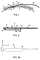
- FIGURE 1 a skull is shown in which a burr hole 12 has been drilled. Underlying the skull is the dura 16 which encases the brain, and beneath the dura is the cerebrum 14.
- An epidural oxygenation sensor 20 is inserted through the burr hole 12 for measurement of the oxygenation of blood flowing in the dura 16.
- the sensor 20 is inserted through the burr hole and slides between the skull 10 and the dura 16, where it is shielded from ambient light entering the burr hole.
- a photodetector 24 and LED's 22 which face the dura through optical windows in the sensor.
- the photodetector and LED's are mounted on flexible printed wiring which is connected to a sensor cable 26.
- the sensor cable is connected to a pulse oximeter (not shown), which provides drive pulses for the LED's, receives electrical signals from the photodetector, and processes the received electrical signals to produce an indication of the oxygen saturation of blood in the dura.
- the sensor is operated in a reflective mode, whereby light at different wavelengths emitted by the LED's is reflected by the blood in the dura and the reflected light is received by the photodetector.
- the sensor 20 comprises a photodetector 24 and an adjacent pair of LED's 22a and 22b which are surface mounted to leads of flexible printed wiring 28 such as 25.4 micron (0.001 inch) KaptonTM wiring.
- flexible printed wiring 28 such as 25.4 micron (0.001 inch) KaptonTM wiring.
- the use of surface mounted components and the printed wiring provide a thin sensor which minimizes cerebral compression.
- Separating the LED's and the photodetector is a light barrier 25 which prevents the direct transmission of light from the LED's to the photodetector.
- the light barrier may be provided by an opaque epoxy material, but in a preferred embodiment the light barrier is formed of a thin sheet of copper foil.
- the copper foil not only effectively blocks light from the LED's, but is also connected to a grounded lead of the flexible printed wiring. The copper foil thus shields the photodetector from radio frequency interference such as that emanated during pulsing of the LED's.
- the foregoing components are encapsulated by a soft coating 30 of silicone rubber or polyurethane material.
- the soft coating smoothly rounds the corners and edges of the sensor which prevents injury to the dura by the sensor.
- the coating also hermetically seals the components from moisture and other environmental factors.
- the coating 30 is optically transmissive to light at the wavelengths of the LED's where it overlies the lower surfaces of the photodetector and the LED's from which light is transmitted and received by these components.
- FIGURE 2a is a perspective view of the sensor 20 of FIGURE 2, referenced to x, y, and z axes.
- the coating 30 provides the sensor with a smooth, gently rounded profile such as the rounded distal end 27.
- the sensor is relatively stiff along the portion of the printed wiring where the components are mounted to maintain their relative alignment.
- the sensor In the x dimension the sensor is fairly stiff so that it may be inserted and guided beneath the skull and in contact with the dura.
- the z dimension the sensor is stiff to provide maneuverability during placement of the sensor.
- the proximal the components is flexible to curve through the burr hole and under the skull, which may have a thickness of 2 to 20 mm depending upon the patient.
- the senor In order to be capable of sliding between the skull and the dura the sensor should be thin in the y dimension so as not to injure the patient.
- the sensor thickness in this dimension should be not greater than 4 mm, and most preferably not greater than 2.5 mm.
- the sensor should also be not less than one millimeter in thickness to maintain continuous contact with the dura. This will reduce the occurrence of motion artifacts, as the dura can move as much as 1 ⁇ 2 mm away from the skull during hyperventilation of the patient, for instance.
- FIGURE 2 the photodetector 24 is located toward the distal end 27 of the sensor with respect to the LED's 22. This distal placement of the photodetector keeps the photodetector well removed from the burr hole and ambient light passing through the burr hole.
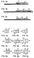
- FIGURES 3a-3c show other component orientations which may be employed in different sensor embodiments.
- the LED's 22′ are canted toward the dura where the dura overlies the photodetector 24, which improves the efficiency of light reflectance.
- the canted LED's are supported by a filler of the coating material 30.
- FIGURE 3b two pairs of LED's 22 ⁇ are located on either side of the phototdetector 24 to illuminate the dura from both sides of the photodetector.
- the pair of LED's 22 is centrally located between a pair of photodetectors 24′, the latter being canted toward the area of the dura illuminated above the LED's.
- FIGURES 4a-6c show component configurations which can fit through a 14 mm diameter burr hole.
- FIGURES 4a-4c show plan views of component layouts for the single photodetector and pair of LED's employed in the sensors of FIGURES 2 and 3a.
- FIGURE 4a the LED's 22′ and the photodetector are arranged in a layout which measures 8.2 mm by 6.3 mm.
- the rectangular layout measures 10.5 mm by 5.3 mm, and in FIGURE 4c the rectangular layout measures 9.3 mm by 5.7 mm.
- the coating material 30 is shown in the area outside the boundaries of the electrical components.
- FIGURES 5a-5c show component layouts for a 14 mm diameter burr hole using two pairs of LED's 22 ⁇ and one photodetector 24.
- the rectangular layout measures 10.8 mm by 7.0 mm
- in FIGURE 5b the layout measures 13.0 mm by 5.5 mm
- in FIGURE 5c the alyout measures 8.2 mm by 7.3 mm.
- FIGURES 6a-6c show component layouts using two photodetectors 24′ and one or two pairs of LED's 22 or 22 ⁇ .
- FIGURE 6a the rectangular layout measures 8.1 mm by 6.8 mm
- in FIGURE 6b the layout measures 11.5 mm by 6.8 mm
- in FIGURE 6c the layout measures 8.6 mm by 7.5 mm.
- each LED pair had an area of 3.0 mm by 4.2 mm.
- the photodetectors in FIGURES 6a and 6c had an area of 2.25 mm by 6.25 mm.
- the photodetectors each had an area of 4.0 mm by 6.25 mm.
- FIGURE 7 is an electrical schematic of the sensor 20 of FIGURE 2.
- the two LED's 22a and 22b are connected in parallel and are parallelled by back-biased diodes 23 and 25.
- the anodes of each pair of components are connected to respective resistors of values chosen in correspondence with the drive current to be supplied to the LED's.
- the connected cathodes of the LED's are likewise coupled to a biasing resistor.
- the resistors may be mounted in line with the flexible printed wiring, such as the points 32a-32d at which the wiring joins the cable to the pulse oximeter monitor.
Abstract
Description
- This invention relates to sensors for determining the oxygen saturation of tissues within the skull and, in particular, to such sensors which are placed epidurally through the skull to measure oxygen saturation.
- During neurological and neurologically related surgical procedures it is oftentimes desirable to continuously monitor the oxygenation of blood which is supplied to the brain. Frequently access is gained to the brain through a borehole in the skull, and a sensor which measures oxygenation can then be inserted through such a borehole. A sensor should then exhibit numerous design and performance criteria in order to operate satisfactorily in this environment. The sensor must be capable of insertion through the borehole so as to contact tissue where oxygen saturation is to be measured. The sensor must be soft so that it does not damage neurological tissue, yet be sufficiently rigid in certain dimensions so that it can be maneuvered from outside the skull. It also must be sized to fit inside the borehole and in the location where measurements are to be taken. Furthermore, the sensor must be designed so as to eliminate detection of ambient light which will interfere with detection of the desired optical signals. The sensor must also prevent the detection of directly transmitted light from the light source of the sensor.
- EP-A-0314937 discloses an implantable blood oxygen sensor, particularly for use in an implantable pacemaker lead. A single light emitting diode and phototransistor means are hermetically sealed within a cylindrical body of transparent material, e.g. glass.
- EP-A-0257954 discloses an oxygen sensing pacemaker having the features recited in the preamble of claim 1. As in EP-A-0314937, the light emitting diodes and the photodetector are sealed within a rigid sleeve.
- In accordance with the principles of the present invention, an optical sensor is provided which is particularly suitable for epidural measurement of blood oxygenation. The sensor of the present invention recited in claim 1 comprises a pair of light emitting diodes (LED's), and a photodetector for receiving light emitted by the LED's which has been reflected from adjacent blood perfused tissue. The LED's and the photodetector are mounted on flexible printed wiring which transmits signals to the LED's and from the photodiode. The components are encapsulated in a soft polymer which is biocompatible. The resultant sensor is thus capable of operation in an epidural environment, and is further capable of being maneuvered into the desired position for epidural measurements.
- In the drawings:
- FIGURE 1 illustrates a cross-sectional view of the use of an epidural oxygenation sensor constructed in accordance with the present invention;
- FIGURE 2 is a side cross-sectional view of an epidural oxygenation sensor constructed in accordance with the principles of the present invention;
- FIGURE 2a is a perspective view of an epidural oxygenation sensor constructed in accordance with the principles of the present invention;
- FIGURES 3a-3c are cross-sectional views of different embodiments of epidural oxygenation sensors of the present invention;
- FIGURES 4a-6c are plan views of different placements of LED's and photodiodes of epidural oxygenation sensors of the present invention;
- FIGURE 7 is an electrical schematic of the components of the epidural oxygenation sensor of FIGURE 2; and
- Referring first to FIGURE 1, a skull is shown in which a
burr hole 12 has been drilled. Underlying the skull is thedura 16 which encases the brain, and beneath the dura is thecerebrum 14. Anepidural oxygenation sensor 20 is inserted through theburr hole 12 for measurement of the oxygenation of blood flowing in thedura 16. Thesensor 20 is inserted through the burr hole and slides between theskull 10 and thedura 16, where it is shielded from ambient light entering the burr hole. At the distal end of thesensor 20 is aphotodetector 24 and LED's 22 which face the dura through optical windows in the sensor. The photodetector and LED's are mounted on flexible printed wiring which is connected to asensor cable 26. The sensor cable is connected to a pulse oximeter (not shown), which provides drive pulses for the LED's, receives electrical signals from the photodetector, and processes the received electrical signals to produce an indication of the oxygen saturation of blood in the dura. The sensor is operated in a reflective mode, whereby light at different wavelengths emitted by the LED's is reflected by the blood in the dura and the reflected light is received by the photodetector. - As shown in FIGURE 2, the
sensor 20 comprises aphotodetector 24 and an adjacent pair of LED's 22a and 22b which are surface mounted to leads of flexible printedwiring 28 such as 25.4 micron (0.001 inch) Kapton™ wiring. The use of surface mounted components and the printed wiring provide a thin sensor which minimizes cerebral compression. Separating the LED's and the photodetector is alight barrier 25 which prevents the direct transmission of light from the LED's to the photodetector. The light barrier may be provided by an opaque epoxy material, but in a preferred embodiment the light barrier is formed of a thin sheet of copper foil. The copper foil not only effectively blocks light from the LED's, but is also connected to a grounded lead of the flexible printed wiring. The copper foil thus shields the photodetector from radio frequency interference such as that emanated during pulsing of the LED's. - The foregoing components are encapsulated by a
soft coating 30 of silicone rubber or polyurethane material. The soft coating smoothly rounds the corners and edges of the sensor which prevents injury to the dura by the sensor. The coating also hermetically seals the components from moisture and other environmental factors. Thecoating 30 is optically transmissive to light at the wavelengths of the LED's where it overlies the lower surfaces of the photodetector and the LED's from which light is transmitted and received by these components. - FIGURE 2a is a perspective view of the
sensor 20 of FIGURE 2, referenced to x, y, and z axes. As mentioned above, thecoating 30 provides the sensor with a smooth, gently rounded profile such as the roundeddistal end 27. The sensor is relatively stiff along the portion of the printed wiring where the components are mounted to maintain their relative alignment. In the x dimension the sensor is fairly stiff so that it may be inserted and guided beneath the skull and in contact with the dura. In the z dimension the sensor is stiff to provide maneuverability during placement of the sensor. In the y dimension the sensor proximal the components is flexible to curve through the burr hole and under the skull, which may have a thickness of 2 to 20 mm depending upon the patient. - In order to be capable of sliding between the skull and the dura the sensor should be thin in the y dimension so as not to injure the patient. Preferably the sensor thickness in this dimension should be not greater than 4 mm, and most preferably not greater than 2.5 mm. The sensor should also be not less than one millimeter in thickness to maintain continuous contact with the dura. This will reduce the occurrence of motion artifacts, as the dura can move as much as ½ mm away from the skull during hyperventilation of the patient, for instance.
- In the embodiment of FIGURE 2 the
photodetector 24 is located toward thedistal end 27 of the sensor with respect to the LED's 22. This distal placement of the photodetector keeps the photodetector well removed from the burr hole and ambient light passing through the burr hole. FIGURES 3a-3c show other component orientations which may be employed in different sensor embodiments. In FIGURE 3a the LED's 22′ are canted toward the dura where the dura overlies thephotodetector 24, which improves the efficiency of light reflectance. The canted LED's are supported by a filler of thecoating material 30. In FIGURE 3b two pairs of LED's 22˝ are located on either side of thephototdetector 24 to illuminate the dura from both sides of the photodetector. In FIGURE 3c the pair of LED's 22 is centrally located between a pair ofphotodetectors 24′, the latter being canted toward the area of the dura illuminated above the LED's. - It is desirable for the optical windows of the components which face the dura to be as large as possible so as to maximize optical transmission efficiency. Opposing this desire is the constraint that the sensor must be sized to fit through the burr hole in the skull. To determine the largest components which may fit through a given burr hole diameter, rectangular configurations of components may be calculated which are capable of fitting through the burr hole. FIGURES 4a-6c show component configurations which can fit through a 14 mm diameter burr hole. FIGURES 4a-4c show plan views of component layouts for the single photodetector and pair of LED's employed in the sensors of FIGURES 2 and 3a. In FIGURE 4a the LED's 22′ and the photodetector are arranged in a layout which measures 8.2 mm by 6.3 mm. In FIGURE 4b the rectangular layout measures 10.5 mm by 5.3 mm, and in FIGURE 4c the rectangular layout measures 9.3 mm by 5.7 mm. In each layout the
coating material 30 is shown in the area outside the boundaries of the electrical components. - FIGURES 5a-5c show component layouts for a 14 mm diameter burr hole using two pairs of LED's 22˝ and one
photodetector 24. In FIGURE 5a the rectangular layout measures 10.8 mm by 7.0 mm; in FIGURE 5b the layout measures 13.0 mm by 5.5 mm; and in FIGURE 5c the alyout measures 8.2 mm by 7.3 mm. In a similar manner, FIGURES 6a-6c show component layouts using twophotodetectors 24′ and one or two pairs of LED's 22 or 22˝ . In FIGURE 6a the rectangular layout measures 8.1 mm by 6.8 mm; in FIGURE 6b the layout measures 11.5 mm by 6.8 mm; and in FIGURE 6c the layout measures 8.6 mm by 7.5 mm. - In FIGURES 4a-6c each LED pair had an area of 3.0 mm by 4.2 mm. The photodetectors in FIGURES 6a and 6c had an area of 2.25 mm by 6.25 mm. In the remaining layouts the photodetectors each had an area of 4.0 mm by 6.25 mm.
- FIGURE 7 is an electrical schematic of the
sensor 20 of FIGURE 2. The two LED's 22a and 22b are connected in parallel and are parallelled by back-biaseddiodes points 32a-32d at which the wiring joins the cable to the pulse oximeter monitor.
Claims (11)
- A sensor for measuring cerebral oxygen saturation through a burr hole (12) in the skull by optical reflectance comprising:
a length of flexible wiring (28) having a distal end and a proximal end which is to be connected to an oximeter;
a photodetector (24) electrically connected to said flexible wiring (28) in the proximity of said distal end;
a pair of light emitting diodes (22a, 22b) connected to said flexible wiring adjacent to said photodetector (24); and
a coating (30) encapsulating said photodetector (24) and said light emitting diodes (22a, 22b) and said flexible wiring (28) in the proximity of said photodetector (24) and light emitting diodes (22a, 22b), said coating including optical windows where said coating overlies the optical windows of said photodetector and light emitting diodes which is transmissive to light at the wavelengths of said light emitting diodes,
characterised in that said flexible wiring (28) comprises flexible printed wiring, and said light emitting diodes (22a, 22b) and said photodetector (24) are mounted on said flexible printed wiring. - The sensor of claim 1, further including a light barrier (25) which shields said photodetector (24) from the direct reception of light from said light emitting diodes (22a, 22b).
- The sensor of claim 2, wherein said light barrier (25) comprises opaque epoxy.
- The sensor of claim 2, wherein said light barrier (25) comprises a metal foil.
- The sensor of any one of claims 1 to 4, wherein said coating (30) is silicone rubber.
- The sensor of any one of claims 1 to 4, wherein said coating (30) is polyurethane.
- The sensor of any one of claims 1 to 6, wherein the optical window of said light emitting diodes (22a, 22b) is canted toward the area above said photodetector.
- The sensor of any one of claim 1 to 6, further comprising a second pair of light emitting diodes located adjacent said photodetector (24) and on the opposite side of said photodetector as said first-named pair of light emitting diodes.
- The sensor of any one of claims 1 to 6, further comprising a second photodetector located adjacent said light emitting diodes (22) on the opposite side of said light emitting diodes as said first-named photodetector.
- The sensor of claim 9, wherein said photodetectors (24') are canted toward the area above said light emitting diodes (22).
- The sensor of any one of claims 1 to 10, wherein said photodetector (24) and said light emitting diodes (22) occupy an area sized to fit through a burr hole of a given diameter.
Priority Applications (1)
| Application Number | Priority Date | Filing Date | Title |
|---|---|---|---|
| EP95200028A EP0651968B1 (en) | 1989-08-17 | 1990-08-16 | Epidural oxygen sensor |
Applications Claiming Priority (2)
| Application Number | Priority Date | Filing Date | Title |
|---|---|---|---|
| US07/394,997 US5024226A (en) | 1989-08-17 | 1989-08-17 | Epidural oxygen sensor |
| US394997 | 1989-08-17 |
Related Child Applications (1)
| Application Number | Title | Priority Date | Filing Date |
|---|---|---|---|
| EP95200028.9 Division-Into | 1990-08-16 |
Publications (3)
| Publication Number | Publication Date |
|---|---|
| EP0413588A2 EP0413588A2 (en) | 1991-02-20 |
| EP0413588A3 EP0413588A3 (en) | 1991-10-23 |
| EP0413588B1 true EP0413588B1 (en) | 1996-03-06 |
Family
ID=23561272
Family Applications (2)
| Application Number | Title | Priority Date | Filing Date |
|---|---|---|---|
| EP95200028A Expired - Lifetime EP0651968B1 (en) | 1989-08-17 | 1990-08-16 | Epidural oxygen sensor |
| EP90309019A Expired - Lifetime EP0413588B1 (en) | 1989-08-17 | 1990-08-16 | Epidural oxygen sensor |
Family Applications Before (1)
| Application Number | Title | Priority Date | Filing Date |
|---|---|---|---|
| EP95200028A Expired - Lifetime EP0651968B1 (en) | 1989-08-17 | 1990-08-16 | Epidural oxygen sensor |
Country Status (10)
| Country | Link |
|---|---|
| US (2) | US5024226A (en) |
| EP (2) | EP0651968B1 (en) |
| JP (1) | JPH03228746A (en) |
| KR (1) | KR100191230B1 (en) |
| AT (2) | ATE148323T1 (en) |
| CA (1) | CA2023355A1 (en) |
| DE (2) | DE69025673T2 (en) |
| DK (2) | DK0651968T3 (en) |
| ES (2) | ES2097063T3 (en) |
| GR (1) | GR1001029B (en) |
Families Citing this family (164)
| Publication number | Priority date | Publication date | Assignee | Title |
|---|---|---|---|---|
| FR2652928B1 (en) | 1989-10-05 | 1994-07-29 | Diadix Sa | INTERACTIVE LOCAL INTERVENTION SYSTEM WITHIN A AREA OF A NON-HOMOGENEOUS STRUCTURE. |
| US5361759A (en) * | 1990-07-04 | 1994-11-08 | Charing Cross & Westminster Medical School | Meconium monitoring system |
| DK0471898T3 (en) | 1990-08-22 | 1999-09-06 | Nellcor Puritan Bennett Inc | Fetal Pulse Oximetry Device |
| US5218962A (en) * | 1991-04-15 | 1993-06-15 | Nellcor Incorporated | Multiple region pulse oximetry probe and oximeter |
| US5284139A (en) * | 1991-12-30 | 1994-02-08 | Abbot Laboratories | Hemometrix temperature compensation |
| FR2685865B1 (en) * | 1992-01-08 | 1998-04-10 | Distr App Medicaux Off | OPTICAL SENSOR, PARTICULARLY FOR MEASURING THE OXYGEN SATURATION RATE IN ARTERIAL BLOOD. |
| US5913820A (en) | 1992-08-14 | 1999-06-22 | British Telecommunications Public Limited Company | Position location system |
| WO1994004073A1 (en) * | 1992-08-25 | 1994-03-03 | Zertl Medical Inc. | Blood flow monitoring system |
| US5419322A (en) * | 1993-07-22 | 1995-05-30 | Joseph; Barry M. | Internal apparatus for continuous electrical and oximetric intrapartum monitoring of the fetus |
| DE19506197A1 (en) * | 1995-02-23 | 1996-09-05 | Aesculap Ag | Method and device for determining the location of a body part |
| US5592939A (en) | 1995-06-14 | 1997-01-14 | Martinelli; Michael A. | Method and system for navigating a catheter probe |
| US5839439A (en) * | 1995-11-13 | 1998-11-24 | Nellcor Puritan Bennett Incorporated | Oximeter sensor with rigid inner housing and pliable overmold |
| US6735471B2 (en) * | 1996-04-30 | 2004-05-11 | Medtronic, Inc. | Method and system for endotracheal/esophageal stimulation prior to and during a medical procedure |
| US8036741B2 (en) * | 1996-04-30 | 2011-10-11 | Medtronic, Inc. | Method and system for nerve stimulation and cardiac sensing prior to and during a medical procedure |
| US7269457B2 (en) | 1996-04-30 | 2007-09-11 | Medtronic, Inc. | Method and system for vagal nerve stimulation with multi-site cardiac pacing |
| US6532388B1 (en) | 1996-04-30 | 2003-03-11 | Medtronic, Inc. | Method and system for endotracheal/esophageal stimulation prior to and during a medical procedure |
| US6628987B1 (en) | 2000-09-26 | 2003-09-30 | Medtronic, Inc. | Method and system for sensing cardiac contractions during vagal stimulation-induced cardiopalegia |
| US7225019B2 (en) | 1996-04-30 | 2007-05-29 | Medtronic, Inc. | Method and system for nerve stimulation and cardiac sensing prior to and during a medical procedure |
| US6904318B2 (en) * | 2000-09-26 | 2005-06-07 | Medtronic, Inc. | Method and system for monitoring and controlling systemic and pulmonary circulation during a medical procedure |
| US6449507B1 (en) | 1996-04-30 | 2002-09-10 | Medtronic, Inc. | Method and system for nerve stimulation prior to and during a medical procedure |
| US6231514B1 (en) | 1996-06-26 | 2001-05-15 | Tobo, Llc | Device for use in temporary insertion of a sensor within a patient's body |
| US20040220455A1 (en) * | 1996-06-26 | 2004-11-04 | Lowe Robert I. | Method for monitoring blood characteristics and cardiopulmonary function |
| US5995857A (en) * | 1996-07-01 | 1999-11-30 | Toomim; I. Hershel | Biofeedback of human central nervous system activity using radiation detection |
| US7172143B2 (en) * | 1996-07-22 | 2007-02-06 | Antoine Vandeputte | Method and plant for separating polymeric materials |
| US7014132B2 (en) * | 1996-07-22 | 2006-03-21 | Antoine Vandeputte | Method and plant for separating polymeric materials |
| US5776058A (en) | 1996-08-13 | 1998-07-07 | Nellcor Puritan Bennett Incorporated | Pressure-attached presenting part fetal pulse oximetry sensor |
| DE19638813C1 (en) * | 1996-09-20 | 1998-03-05 | Sican F & E Gmbh Sibet | Measuring device for medical applications with an intracorporeally usable sensor element and method for its production |
| US5851179A (en) | 1996-10-10 | 1998-12-22 | Nellcor Puritan Bennett Incorporated | Pulse oximeter sensor with articulating head |
| US20010003800A1 (en) * | 1996-11-21 | 2001-06-14 | Steven J. Frank | Interventional photonic energy emitter system |
| WO1998022184A1 (en) * | 1996-11-21 | 1998-05-28 | Boston Scientific Corporation | Mucosal ablation using light |
| US6119031A (en) | 1996-11-21 | 2000-09-12 | Boston Scientific Corporation | Miniature spectrometer |
| JP2000508955A (en) * | 1997-02-13 | 2000-07-18 | ジカン・エフ・ウント・エー・ゲーエムベーハー | Implantable measuring device for in vivo measurement of patient data |
| US6238348B1 (en) | 1997-07-22 | 2001-05-29 | Scimed Life Systems, Inc. | Miniature spectrometer system and method |
| US6096065A (en) * | 1997-09-29 | 2000-08-01 | Boston Scientific Corporation | Sheath for tissue spectroscopy |
| US5984861A (en) * | 1997-09-29 | 1999-11-16 | Boston Scientific Corporation | Endofluorescence imaging module for an endoscope |
| US6185443B1 (en) | 1997-09-29 | 2001-02-06 | Boston Scientific Corporation | Visible display for an interventional device |
| US6324418B1 (en) | 1997-09-29 | 2001-11-27 | Boston Scientific Corporation | Portable tissue spectroscopy apparatus and method |
| US6479523B1 (en) * | 1997-08-26 | 2002-11-12 | Emory University | Pharmacologic drug combination in vagal-induced asystole |
| US6226548B1 (en) | 1997-09-24 | 2001-05-01 | Surgical Navigation Technologies, Inc. | Percutaneous registration apparatus and method for use in computer-assisted surgical navigation |
| US6021343A (en) | 1997-11-20 | 2000-02-01 | Surgical Navigation Technologies | Image guided awl/tap/screwdriver |
| US6348058B1 (en) | 1997-12-12 | 2002-02-19 | Surgical Navigation Technologies, Inc. | Image guided spinal surgery guide, system, and method for use thereof |
| US6289229B1 (en) | 1998-01-20 | 2001-09-11 | Scimed Life Systems, Inc. | Readable probe array for in vivo use |
| US6080294A (en) * | 1998-07-15 | 2000-06-27 | Atwood Industries, Inc. | Gas sensor with dual electrolytes |
| US6477400B1 (en) | 1998-08-20 | 2002-11-05 | Sofamor Danek Holdings, Inc. | Fluoroscopic image guided orthopaedic surgery system with intraoperative registration |
| US6482182B1 (en) * | 1998-09-03 | 2002-11-19 | Surgical Navigation Technologies, Inc. | Anchoring system for a brain lead |
| US6321104B1 (en) * | 1998-11-05 | 2001-11-20 | Medtronic, Inc. | Burr hole cap for fixation of cranial lead |
| US6470207B1 (en) | 1999-03-23 | 2002-10-22 | Surgical Navigation Technologies, Inc. | Navigational guidance via computer-assisted fluoroscopic imaging |
| JP2003503119A (en) * | 1999-06-25 | 2003-01-28 | エモリ ユニバーシティ | Vagal nerve stimulation device and method |
| US6381485B1 (en) | 1999-10-28 | 2002-04-30 | Surgical Navigation Technologies, Inc. | Registration of human anatomy integrated for electromagnetic localization |
| US6438397B1 (en) * | 1999-10-28 | 2002-08-20 | Gerald G. Bosquet | Method and apparatus for analyte detection using intradermally implanted skin port |
| US8644907B2 (en) | 1999-10-28 | 2014-02-04 | Medtronic Navigaton, Inc. | Method and apparatus for surgical navigation |
| US6493573B1 (en) | 1999-10-28 | 2002-12-10 | Winchester Development Associates | Method and system for navigating a catheter probe in the presence of field-influencing objects |
| US11331150B2 (en) | 1999-10-28 | 2022-05-17 | Medtronic Navigation, Inc. | Method and apparatus for surgical navigation |
| US7366562B2 (en) | 2003-10-17 | 2008-04-29 | Medtronic Navigation, Inc. | Method and apparatus for surgical navigation |
| US8239001B2 (en) | 2003-10-17 | 2012-08-07 | Medtronic Navigation, Inc. | Method and apparatus for surgical navigation |
| US6499488B1 (en) | 1999-10-28 | 2002-12-31 | Winchester Development Associates | Surgical sensor |
| US6474341B1 (en) | 1999-10-28 | 2002-11-05 | Surgical Navigation Technologies, Inc. | Surgical communication and power system |
| US6725080B2 (en) | 2000-03-01 | 2004-04-20 | Surgical Navigation Technologies, Inc. | Multiple cannula image guided tool for image guided procedures |
| US6535756B1 (en) | 2000-04-07 | 2003-03-18 | Surgical Navigation Technologies, Inc. | Trajectory storage apparatus and method for surgical navigation system |
| US7085400B1 (en) | 2000-06-14 | 2006-08-01 | Surgical Navigation Technologies, Inc. | System and method for image based sensor calibration |
| US7010351B2 (en) | 2000-07-13 | 2006-03-07 | Northstar Neuroscience, Inc. | Methods and apparatus for effectuating a lasting change in a neural-function of a patient |
| US7756584B2 (en) | 2000-07-13 | 2010-07-13 | Advanced Neuromodulation Systems, Inc. | Methods and apparatus for effectuating a lasting change in a neural-function of a patient |
| US7024247B2 (en) | 2001-10-15 | 2006-04-04 | Northstar Neuroscience, Inc. | Systems and methods for reducing the likelihood of inducing collateral neural activity during neural stimulation threshold test procedures |
| US7831305B2 (en) | 2001-10-15 | 2010-11-09 | Advanced Neuromodulation Systems, Inc. | Neural stimulation system and method responsive to collateral neural activity |
| US7672730B2 (en) | 2001-03-08 | 2010-03-02 | Advanced Neuromodulation Systems, Inc. | Methods and apparatus for effectuating a lasting change in a neural-function of a patient |
| US7236831B2 (en) * | 2000-07-13 | 2007-06-26 | Northstar Neuroscience, Inc. | Methods and apparatus for effectuating a lasting change in a neural-function of a patient |
| US7146217B2 (en) * | 2000-07-13 | 2006-12-05 | Northstar Neuroscience, Inc. | Methods and apparatus for effectuating a change in a neural-function of a patient |
| US7305268B2 (en) | 2000-07-13 | 2007-12-04 | Northstar Neurscience, Inc. | Systems and methods for automatically optimizing stimulus parameters and electrode configurations for neuro-stimulators |
| JP3718500B2 (en) | 2000-07-21 | 2005-11-24 | ウニヴェルシュタート チューリッヒ | Probe and apparatus for measuring brain hemodynamics and oxygen treatment |
| US6487446B1 (en) * | 2000-09-26 | 2002-11-26 | Medtronic, Inc. | Method and system for spinal cord stimulation prior to and during a medical procedure |
| US6466809B1 (en) | 2000-11-02 | 2002-10-15 | Datex-Ohmeda, Inc. | Oximeter sensor having laminated housing with flat patient interface surface |
| US7299096B2 (en) | 2001-03-08 | 2007-11-20 | Northstar Neuroscience, Inc. | System and method for treating Parkinson's Disease and other movement disorders |
| KR100400838B1 (en) * | 2001-05-07 | 2003-10-08 | 대한민국 | Automated apparatus identifying the epidural space to assist epidural anesthesia |
| US6636757B1 (en) | 2001-06-04 | 2003-10-21 | Surgical Navigation Technologies, Inc. | Method and apparatus for electromagnetic navigation of a surgical probe near a metal object |
| US6947786B2 (en) | 2002-02-28 | 2005-09-20 | Surgical Navigation Technologies, Inc. | Method and apparatus for perspective inversion |
| US7221981B2 (en) | 2002-03-28 | 2007-05-22 | Northstar Neuroscience, Inc. | Electrode geometries for efficient neural stimulation |
| US6990368B2 (en) | 2002-04-04 | 2006-01-24 | Surgical Navigation Technologies, Inc. | Method and apparatus for virtual digital subtraction angiography |
| US7998062B2 (en) | 2004-03-29 | 2011-08-16 | Superdimension, Ltd. | Endoscope structures and techniques for navigating to a target in branched structure |
| US6717804B1 (en) * | 2002-09-30 | 2004-04-06 | Hewlett-Packard Development Company, L.P. | Light-emitting lock device control element and electronic device including the same |
| US6716176B1 (en) | 2002-09-30 | 2004-04-06 | Tobo, Llc | Device for use in temporary insertion of a sensor within a patient's body |
| US7010337B2 (en) * | 2002-10-24 | 2006-03-07 | Furnary Anthony P | Method and apparatus for monitoring blood condition and cardiopulmonary function |
| US6731962B1 (en) * | 2002-10-31 | 2004-05-04 | Smiths Medical Pm Inc | Finger oximeter with remote telecommunications capabilities and system therefor |
| US7236830B2 (en) | 2002-12-10 | 2007-06-26 | Northstar Neuroscience, Inc. | Systems and methods for enhancing or optimizing neural stimulation therapy for treating symptoms of Parkinson's disease and/or other movement disorders |
| US7697972B2 (en) | 2002-11-19 | 2010-04-13 | Medtronic Navigation, Inc. | Navigation system for cardiac therapies |
| US7599730B2 (en) | 2002-11-19 | 2009-10-06 | Medtronic Navigation, Inc. | Navigation system for cardiac therapies |
| US7302298B2 (en) | 2002-11-27 | 2007-11-27 | Northstar Neuroscience, Inc | Methods and systems employing intracranial electrodes for neurostimulation and/or electroencephalography |
| US20050075680A1 (en) | 2003-04-18 | 2005-04-07 | Lowry David Warren | Methods and systems for intracranial neurostimulation and/or sensing |
| US7565199B2 (en) | 2002-12-09 | 2009-07-21 | Advanced Neuromodulation Systems, Inc. | Methods for treating and/or collecting information regarding neurological disorders, including language disorders |
| US7660623B2 (en) | 2003-01-30 | 2010-02-09 | Medtronic Navigation, Inc. | Six degree of freedom alignment display for medical procedures |
| US7542791B2 (en) | 2003-01-30 | 2009-06-02 | Medtronic Navigation, Inc. | Method and apparatus for preplanning a surgical procedure |
| US20040215067A1 (en) * | 2003-04-24 | 2004-10-28 | Stiger Mark L. | Flow sensor device for endoscopic third ventriculostomy |
| WO2005000090A2 (en) * | 2003-05-30 | 2005-01-06 | Medi-Screw, Inc. | Medical implant systems |
| US7559931B2 (en) | 2003-06-09 | 2009-07-14 | OrthAlign, Inc. | Surgical orientation system and method |
| AU2004261290A1 (en) | 2003-08-01 | 2005-02-10 | Northstar Neuroscience, Inc. | Apparatus and methods for applying neural stimulation to a patient |
| US7313430B2 (en) | 2003-08-28 | 2007-12-25 | Medtronic Navigation, Inc. | Method and apparatus for performing stereotactic surgery |
| EP2316328B1 (en) | 2003-09-15 | 2012-05-09 | Super Dimension Ltd. | Wrap-around holding device for use with bronchoscopes |
| ES2432616T3 (en) | 2003-09-15 | 2013-12-04 | Covidien Lp | Accessory system for use with bronchoscopes |
| US7835778B2 (en) | 2003-10-16 | 2010-11-16 | Medtronic Navigation, Inc. | Method and apparatus for surgical navigation of a multiple piece construct for implantation |
| US7840253B2 (en) | 2003-10-17 | 2010-11-23 | Medtronic Navigation, Inc. | Method and apparatus for surgical navigation |
| CA2446663A1 (en) * | 2003-10-24 | 2005-04-24 | Shane Burch | Bone-treatment instrument and method |
| US8764725B2 (en) | 2004-02-09 | 2014-07-01 | Covidien Lp | Directional anchoring mechanism, method and applications thereof |
| US7567834B2 (en) | 2004-05-03 | 2009-07-28 | Medtronic Navigation, Inc. | Method and apparatus for implantation between two vertebral bodies |
| US7604658B2 (en) * | 2004-05-04 | 2009-10-20 | Codman & Shurtleff, Inc. | Multiple lumen sensor attachment |
| NL1026137C2 (en) * | 2004-05-07 | 2005-11-08 | Vanderlande Ind Nederland | Device for sorting products. |
| US7483747B2 (en) | 2004-07-15 | 2009-01-27 | Northstar Neuroscience, Inc. | Systems and methods for enhancing or affecting neural stimulation efficiency and/or efficacy |
| US7565200B2 (en) | 2004-11-12 | 2009-07-21 | Advanced Neuromodulation Systems, Inc. | Systems and methods for selecting stimulation sites and applying treatment, including treatment of symptoms of Parkinson's disease, other movement disorders, and/or drug side effects |
| DE102005008454B4 (en) * | 2005-02-24 | 2014-11-13 | Raumedic Ag | Arrangement with a device for measuring brain parameters |
| US20060282134A1 (en) * | 2005-06-10 | 2006-12-14 | Shapiro Ronald S | Photo-thermal therapeutic device |
| US7835784B2 (en) | 2005-09-21 | 2010-11-16 | Medtronic Navigation, Inc. | Method and apparatus for positioning a reference frame |
| US7856264B2 (en) * | 2005-10-19 | 2010-12-21 | Advanced Neuromodulation Systems, Inc. | Systems and methods for patient interactive neural stimulation and/or chemical substance delivery |
| US20070088404A1 (en) * | 2005-10-19 | 2007-04-19 | Allen Wyler | Methods and systems for improving neural functioning, including cognitive functioning and neglect disorders |
| US8929991B2 (en) | 2005-10-19 | 2015-01-06 | Advanced Neuromodulation Systems, Inc. | Methods for establishing parameters for neural stimulation, including via performance of working memory tasks, and associated kits |
| US7729773B2 (en) | 2005-10-19 | 2010-06-01 | Advanced Neuromodualation Systems, Inc. | Neural stimulation and optical monitoring systems and methods |
| US9168102B2 (en) | 2006-01-18 | 2015-10-27 | Medtronic Navigation, Inc. | Method and apparatus for providing a container to a sterile environment |
| US8112292B2 (en) | 2006-04-21 | 2012-02-07 | Medtronic Navigation, Inc. | Method and apparatus for optimizing a therapy |
| US8660635B2 (en) | 2006-09-29 | 2014-02-25 | Medtronic, Inc. | Method and apparatus for optimizing a computer assisted surgical procedure |
| US8905920B2 (en) | 2007-09-27 | 2014-12-09 | Covidien Lp | Bronchoscope adapter and method |
| US8473032B2 (en) | 2008-06-03 | 2013-06-25 | Superdimension, Ltd. | Feature-based registration method |
| US8218847B2 (en) | 2008-06-06 | 2012-07-10 | Superdimension, Ltd. | Hybrid registration method |
| US8932207B2 (en) | 2008-07-10 | 2015-01-13 | Covidien Lp | Integrated multi-functional endoscopic tool |
| AU2009273863B2 (en) | 2008-07-24 | 2014-12-18 | OrthAlign, Inc. | Systems and methods for joint replacement |
| EP2358310B1 (en) | 2008-09-10 | 2019-07-31 | OrthAlign, Inc. | Hip surgery systems |
| US8165658B2 (en) | 2008-09-26 | 2012-04-24 | Medtronic, Inc. | Method and apparatus for positioning a guide relative to a base |
| US8175681B2 (en) | 2008-12-16 | 2012-05-08 | Medtronic Navigation Inc. | Combination of electromagnetic and electropotential localization |
| KR101034798B1 (en) * | 2009-03-18 | 2011-05-17 | 한국과학기술연구원 | Apparatus for detecting brain conditions |
| KR101081360B1 (en) | 2009-03-25 | 2011-11-08 | 한국과학기술연구원 | Photostimulation array apparatus |
| US8611984B2 (en) | 2009-04-08 | 2013-12-17 | Covidien Lp | Locatable catheter |
| US8118815B2 (en) | 2009-07-24 | 2012-02-21 | OrthAlign, Inc. | Systems and methods for joint replacement |
| US10869771B2 (en) | 2009-07-24 | 2020-12-22 | OrthAlign, Inc. | Systems and methods for joint replacement |
| US8494613B2 (en) | 2009-08-31 | 2013-07-23 | Medtronic, Inc. | Combination localization system |
| US8494614B2 (en) | 2009-08-31 | 2013-07-23 | Regents Of The University Of Minnesota | Combination localization system |
| US8792951B1 (en) | 2010-02-23 | 2014-07-29 | Vioptix, Inc. | Bone oxygenation measurement |
| US8406868B2 (en) | 2010-04-29 | 2013-03-26 | Medtronic, Inc. | Therapy using perturbation and effect of physiological systems |
| US8620425B2 (en) | 2010-04-29 | 2013-12-31 | Medtronic, Inc. | Nerve signal differentiation in cardiac therapy |
| US8639327B2 (en) | 2010-04-29 | 2014-01-28 | Medtronic, Inc. | Nerve signal differentiation in cardiac therapy |
| WO2011159834A1 (en) | 2010-06-15 | 2011-12-22 | Superdimension, Ltd. | Locatable expandable working channel and method |
| US8706223B2 (en) | 2011-01-19 | 2014-04-22 | Medtronic, Inc. | Preventative vagal stimulation |
| US8718763B2 (en) | 2011-01-19 | 2014-05-06 | Medtronic, Inc. | Vagal stimulation |
| US8781583B2 (en) | 2011-01-19 | 2014-07-15 | Medtronic, Inc. | Vagal stimulation |
| US8781582B2 (en) | 2011-01-19 | 2014-07-15 | Medtronic, Inc. | Vagal stimulation |
| US8725259B2 (en) | 2011-01-19 | 2014-05-13 | Medtronic, Inc. | Vagal stimulation |
| WO2013090658A1 (en) | 2011-12-14 | 2013-06-20 | The Trustees Of The University Of Pennsylvania | Fiber optic flow and oxygenation monitoring using diffuse correlation and reflectance |
| WO2013173700A1 (en) | 2012-05-18 | 2013-11-21 | OrthAlign, Inc. | Devices and methods for knee arthroplasty |
| US9649160B2 (en) | 2012-08-14 | 2017-05-16 | OrthAlign, Inc. | Hip replacement navigation system and method |
| EP2906365B1 (en) | 2012-10-12 | 2021-06-09 | Blue Sky Mines Ltd. | Method of and system for treating incinerated waste |
| DE102012110358B4 (en) * | 2012-10-30 | 2016-04-07 | Leibniz-Institut für Neurobiologie Magdeburg | Microelectrode array |
| KR101599603B1 (en) * | 2013-08-26 | 2016-03-03 | 경북대학교 산학협력단 | Medical inserting apparatus |
| US10952593B2 (en) | 2014-06-10 | 2021-03-23 | Covidien Lp | Bronchoscope adapter |
| KR101639887B1 (en) | 2014-11-11 | 2016-07-14 | 경북대학교 산학협력단 | A system for fixing cervical vertebrae and a driver used for an appratus for fixing cervical vertebrae |
| KR101608949B1 (en) | 2014-11-19 | 2016-04-04 | 경북대학교 산학협력단 | A system for fixing cervical vertebrae, an appratus for fixing cervical vertebrae and a driver used for an appratus for fixing cervical vertebrae |
| US10363149B2 (en) | 2015-02-20 | 2019-07-30 | OrthAlign, Inc. | Hip replacement navigation system and method |
| US10716499B1 (en) * | 2015-03-24 | 2020-07-21 | Zoll Medical Corporation | Physiological monitoring by optical spectroscopy |
| US10426555B2 (en) | 2015-06-03 | 2019-10-01 | Covidien Lp | Medical instrument with sensor for use in a system and method for electromagnetic navigation |
| KR101670768B1 (en) | 2015-07-16 | 2016-10-31 | 경북대학교 산학협력단 | Screw anchor assembly |
| US10874445B2 (en) | 2015-10-13 | 2020-12-29 | Kyungpook National University Industry-Academic Cooperation Foundation | Screw fixing apparatus |
| US9962134B2 (en) | 2015-10-28 | 2018-05-08 | Medtronic Navigation, Inc. | Apparatus and method for maintaining image quality while minimizing X-ray dosage of a patient |
| KR101712610B1 (en) | 2015-12-29 | 2017-03-06 | 경북대학교 산학협력단 | A rod connecter |
| US10478254B2 (en) | 2016-05-16 | 2019-11-19 | Covidien Lp | System and method to access lung tissue |
| KR101791004B1 (en) | 2016-06-08 | 2017-10-27 | 경북대학교 산학협력단 | Screw anchor assembly and a method for using the same to pedicle screw instrumentation |
| AU2018236205B2 (en) | 2017-03-14 | 2023-10-12 | OrthAlign, Inc. | Soft tissue measurement and balancing systems and methods |
| JP2020511231A (en) | 2017-03-14 | 2020-04-16 | オースアライン・インコーポレイテッド | Hip replacement navigation system and method |
| US10383610B2 (en) | 2017-10-27 | 2019-08-20 | Intuitap Medical, Inc. | Tactile sensing and needle guidance device |
| US11219489B2 (en) | 2017-10-31 | 2022-01-11 | Covidien Lp | Devices and systems for providing sensors in parallel with medical tools |
| EP4292524A1 (en) | 2022-06-17 | 2023-12-20 | Carag Ag | Intracranial catheter for measuring a flow of blood |
Citations (1)
| Publication number | Priority date | Publication date | Assignee | Title |
|---|---|---|---|---|
| EP0257954A2 (en) * | 1986-08-15 | 1988-03-02 | Medtronic, Inc. | Oxygen sensing pacemaker |
Family Cites Families (19)
| Publication number | Priority date | Publication date | Assignee | Title |
|---|---|---|---|---|
| US4281645A (en) * | 1977-06-28 | 1981-08-04 | Duke University, Inc. | Method and apparatus for monitoring metabolism in body organs |
| US4328813A (en) * | 1980-10-20 | 1982-05-11 | Medtronic, Inc. | Brain lead anchoring system |
| JPS57177735A (en) * | 1981-04-27 | 1982-11-01 | Toyoda Chuo Kenkyusho Kk | Telemeter type brain nanometer |
| US4541439A (en) * | 1982-04-23 | 1985-09-17 | American Home Products Corporation (Del.) | Monitoring of capillary blood flow |
| US4621643A (en) * | 1982-09-02 | 1986-11-11 | Nellcor Incorporated | Calibrated optical oximeter probe |
| US4658825A (en) * | 1982-09-24 | 1987-04-21 | International Biomedics, Inc. | Spiral probe for simultaneous electrical and chemical monitoring of a fetus |
| JPS59140711U (en) * | 1983-03-10 | 1984-09-20 | 塩野義製薬株式会社 | Insertion needle for brain tissue exploration |
| US4646752A (en) * | 1983-04-25 | 1987-03-03 | Swann Karl W | Adjustable intracranial pressure measuring screw |
| EP0135840A3 (en) * | 1983-08-30 | 1986-06-11 | Nellcor Incorporated | Perinatal oximeter |
| US4938218A (en) * | 1983-08-30 | 1990-07-03 | Nellcor Incorporated | Perinatal pulse oximetry sensor |
| EP0248103A1 (en) * | 1986-06-06 | 1987-12-09 | Hellige GmbH | Adapter for exchangeably implanting bio-sensors in the skull bone |
| US4714080A (en) * | 1986-10-06 | 1987-12-22 | Nippon Colin Co., Ltd. | Method and apparatus for noninvasive monitoring of arterial blood oxygen saturation |
| US4865038A (en) * | 1986-10-09 | 1989-09-12 | Novametrix Medical Systems, Inc. | Sensor appliance for non-invasive monitoring |
| US4784150A (en) * | 1986-11-04 | 1988-11-15 | Research Corporation | Surgical retractor and blood flow monitor |
| JPS63252239A (en) * | 1987-04-09 | 1988-10-19 | Sumitomo Electric Ind Ltd | Reflection type oxymeter |
| DE3854781T2 (en) * | 1987-10-08 | 1996-05-02 | Pacesetter Ab | Implantable blood oxygen sensor and method of using it |
| EP0323535A1 (en) * | 1988-01-05 | 1989-07-12 | Hellige GmbH | Adapter for exchangeable implantation of biosensors in the skull bone |
| US4825872A (en) * | 1988-08-05 | 1989-05-02 | Critikon, Inc. | Finger sensor for pulse oximetry system |
| AU4968790A (en) * | 1989-01-10 | 1990-08-13 | Neurodynamics, Inc. | Infrared oximetry measuring device |
-
1989
- 1989-08-17 US US07/394,997 patent/US5024226A/en not_active Expired - Fee Related
-
1990
- 1990-08-15 CA CA002023355A patent/CA2023355A1/en not_active Abandoned
- 1990-08-16 GR GR900100617A patent/GR1001029B/en unknown
- 1990-08-16 DK DK95200028.9T patent/DK0651968T3/da active
- 1990-08-16 ES ES95200028T patent/ES2097063T3/en not_active Expired - Lifetime
- 1990-08-16 AT AT95200028T patent/ATE148323T1/en not_active IP Right Cessation
- 1990-08-16 DE DE69025673T patent/DE69025673T2/en not_active Expired - Fee Related
- 1990-08-16 EP EP95200028A patent/EP0651968B1/en not_active Expired - Lifetime
- 1990-08-16 AT AT90309019T patent/ATE134849T1/en not_active IP Right Cessation
- 1990-08-16 ES ES90309019T patent/ES2084662T3/en not_active Expired - Lifetime
- 1990-08-16 DE DE69029869T patent/DE69029869T2/en not_active Expired - Fee Related
- 1990-08-16 EP EP90309019A patent/EP0413588B1/en not_active Expired - Lifetime
- 1990-08-16 DK DK90309019.9T patent/DK0413588T3/en active
- 1990-08-17 KR KR1019900012643A patent/KR100191230B1/en not_active IP Right Cessation
- 1990-08-17 JP JP2218009A patent/JPH03228746A/en active Pending
- 1990-11-13 US US07/612,744 patent/US5127407A/en not_active Expired - Fee Related
Patent Citations (1)
| Publication number | Priority date | Publication date | Assignee | Title |
|---|---|---|---|---|
| EP0257954A2 (en) * | 1986-08-15 | 1988-03-02 | Medtronic, Inc. | Oxygen sensing pacemaker |
Also Published As
| Publication number | Publication date |
|---|---|
| KR910004155A (en) | 1991-03-28 |
| GR900100617A (en) | 1991-12-30 |
| DK0413588T3 (en) | 1996-07-22 |
| JPH03228746A (en) | 1991-10-09 |
| ES2084662T3 (en) | 1996-05-16 |
| US5024226A (en) | 1991-06-18 |
| DE69025673T2 (en) | 1996-08-01 |
| US5127407A (en) | 1992-07-07 |
| DE69029869D1 (en) | 1997-03-13 |
| ATE134849T1 (en) | 1996-03-15 |
| DE69025673D1 (en) | 1996-04-11 |
| DK0651968T3 (en) | 1997-02-24 |
| DE69029869T2 (en) | 1997-06-05 |
| ATE148323T1 (en) | 1997-02-15 |
| EP0413588A2 (en) | 1991-02-20 |
| EP0413588A3 (en) | 1991-10-23 |
| EP0651968B1 (en) | 1997-01-29 |
| EP0651968A1 (en) | 1995-05-10 |
| ES2097063T3 (en) | 1997-03-16 |
| GR1001029B (en) | 1993-03-31 |
| CA2023355A1 (en) | 1991-02-18 |
| KR100191230B1 (en) | 1999-06-15 |
Similar Documents
| Publication | Publication Date | Title |
|---|---|---|
| EP0413588B1 (en) | Epidural oxygen sensor | |
| US20210353190A1 (en) | Noninvasive oximetry optical sensor including disposable and reusable elements | |
| EP1691190B1 (en) | Near infrared spectroscopy device with reusable portion | |
| US5584296A (en) | Patient sensor for optical cerebral oximeters and the like | |
| AU705934B2 (en) | Pulse oximeter and sensor optimized for low saturation | |
| CA2724017C (en) | Non-invasive optical sensor | |
| US11064919B2 (en) | Non-invasive monitor for measuring regional saturation of oxygen | |
| WO1992021281A1 (en) | Apparatus for indicating characteristics of a patient undergoing mri | |
| CA2179303A1 (en) | Fetal pulse oximetry sensor | |
| EP1080683A2 (en) | Laser diode optical transducer assembly for non-invasive spectrophotometric blood oxygenation monitoring | |
| EP1206214A1 (en) | Shielded optical probe and method | |
| EP0821911A1 (en) | Patient monitoring system | |
| CN111657960A (en) | Sensor arrangement | |
| US20230119921A1 (en) | Methods and apparatus for performing physiological measurements using diffuse optical imaging | |
| US20220346673A1 (en) | Methods and apparatus for near infrared spectroscopy |
Legal Events
| Date | Code | Title | Description |
|---|---|---|---|
| PUAI | Public reference made under article 153(3) epc to a published international application that has entered the european phase |
Free format text: ORIGINAL CODE: 0009012 |
|
| AK | Designated contracting states |
Kind code of ref document: A2 Designated state(s): AT BE CH DE DK ES FR GB IT LI LU NL SE |
|
| PUAL | Search report despatched |
Free format text: ORIGINAL CODE: 0009013 |
|
| RHK1 | Main classification (correction) |
Ipc: A61B 5/00 |
|
| AK | Designated contracting states |
Kind code of ref document: A3 Designated state(s): AT BE CH DE DK ES FR GB IT LI LU NL SE |
|
| 17P | Request for examination filed |
Effective date: 19920330 |
|
| 17Q | First examination report despatched |
Effective date: 19940606 |
|
| GRAA | (expected) grant |
Free format text: ORIGINAL CODE: 0009210 |
|
| AK | Designated contracting states |
Kind code of ref document: B1 Designated state(s): AT BE CH DE DK ES FR GB IT LI LU NL SE |
|
| REF | Corresponds to: |
Ref document number: 134849 Country of ref document: AT Date of ref document: 19960315 Kind code of ref document: T |
|
| XX | Miscellaneous (additional remarks) |
Free format text: TEILANMELDUNG 95200028.9 EINGEREICHT AM 16/08/90. |
|
| REG | Reference to a national code |
Ref country code: CH Ref legal event code: NV Representative=s name: E. BLUM & CO. PATENTANWAELTE |
|
| REF | Corresponds to: |
Ref document number: 69025673 Country of ref document: DE Date of ref document: 19960411 |
|
| ET | Fr: translation filed | ||
| REG | Reference to a national code |
Ref country code: ES Ref legal event code: FG2A Ref document number: 2084662 Country of ref document: ES Kind code of ref document: T3 |
|
| ITF | It: translation for a ep patent filed |
Owner name: SOCIETA' ITALIANA BREVETTI S.P.A. |
|
| REG | Reference to a national code |
Ref country code: DK Ref legal event code: T3 |
|
| PLBE | No opposition filed within time limit |
Free format text: ORIGINAL CODE: 0009261 |
|
| STAA | Information on the status of an ep patent application or granted ep patent |
Free format text: STATUS: NO OPPOSITION FILED WITHIN TIME LIMIT |
|
| 26N | No opposition filed | ||
| PG25 | Lapsed in a contracting state [announced via postgrant information from national office to epo] |
Ref country code: DE Effective date: 19970501 |
|
| PGFP | Annual fee paid to national office [announced via postgrant information from national office to epo] |
Ref country code: GB Payment date: 19970807 Year of fee payment: 8 |
|
| PGFP | Annual fee paid to national office [announced via postgrant information from national office to epo] |
Ref country code: FR Payment date: 19970811 Year of fee payment: 8 |
|
| PGFP | Annual fee paid to national office [announced via postgrant information from national office to epo] |
Ref country code: AT Payment date: 19970813 Year of fee payment: 8 |
|
| PGFP | Annual fee paid to national office [announced via postgrant information from national office to epo] |
Ref country code: DK Payment date: 19970815 Year of fee payment: 8 |
|
| PGFP | Annual fee paid to national office [announced via postgrant information from national office to epo] |
Ref country code: SE Payment date: 19970818 Year of fee payment: 8 |
|
| PGFP | Annual fee paid to national office [announced via postgrant information from national office to epo] |
Ref country code: CH Payment date: 19970822 Year of fee payment: 8 |
|
| PGFP | Annual fee paid to national office [announced via postgrant information from national office to epo] |
Ref country code: NL Payment date: 19970826 Year of fee payment: 8 |
|
| PGFP | Annual fee paid to national office [announced via postgrant information from national office to epo] |
Ref country code: LU Payment date: 19970924 Year of fee payment: 8 |
|
| PGFP | Annual fee paid to national office [announced via postgrant information from national office to epo] |
Ref country code: BE Payment date: 19970925 Year of fee payment: 8 |
|
| PGFP | Annual fee paid to national office [announced via postgrant information from national office to epo] |
Ref country code: ES Payment date: 19980814 Year of fee payment: 9 |
|
| PG25 | Lapsed in a contracting state [announced via postgrant information from national office to epo] |
Ref country code: LU Free format text: LAPSE BECAUSE OF NON-PAYMENT OF DUE FEES Effective date: 19980816 Ref country code: GB Free format text: LAPSE BECAUSE OF NON-PAYMENT OF DUE FEES Effective date: 19980816 Ref country code: AT Free format text: LAPSE BECAUSE OF NON-PAYMENT OF DUE FEES Effective date: 19980816 |
|
| PG25 | Lapsed in a contracting state [announced via postgrant information from national office to epo] |
Ref country code: SE Free format text: LAPSE BECAUSE OF NON-PAYMENT OF DUE FEES Effective date: 19980817 |
|
| PG25 | Lapsed in a contracting state [announced via postgrant information from national office to epo] |
Ref country code: LI Free format text: LAPSE BECAUSE OF NON-PAYMENT OF DUE FEES Effective date: 19980831 Ref country code: DK Free format text: LAPSE BECAUSE OF NON-PAYMENT OF DUE FEES Effective date: 19980831 Ref country code: CH Free format text: LAPSE BECAUSE OF NON-PAYMENT OF DUE FEES Effective date: 19980831 Ref country code: BE Free format text: LAPSE BECAUSE OF NON-PAYMENT OF DUE FEES Effective date: 19980831 |
|
| BERE | Be: lapsed |
Owner name: CRITIKON INC. Effective date: 19980831 |
|
| PG25 | Lapsed in a contracting state [announced via postgrant information from national office to epo] |
Ref country code: NL Free format text: LAPSE BECAUSE OF NON-PAYMENT OF DUE FEES Effective date: 19990301 |
|
| GBPC | Gb: european patent ceased through non-payment of renewal fee |
Effective date: 19980816 |
|
| REG | Reference to a national code |
Ref country code: CH Ref legal event code: PL |
|
| PG25 | Lapsed in a contracting state [announced via postgrant information from national office to epo] |
Ref country code: FR Free format text: LAPSE BECAUSE OF NON-PAYMENT OF DUE FEES Effective date: 19990430 |
|
| EUG | Se: european patent has lapsed |
Ref document number: 90309019.9 |
|
| NLV4 | Nl: lapsed or anulled due to non-payment of the annual fee |
Effective date: 19990301 |
|
| REG | Reference to a national code |
Ref country code: FR Ref legal event code: ST |
|
| PG25 | Lapsed in a contracting state [announced via postgrant information from national office to epo] |
Ref country code: ES Free format text: LAPSE BECAUSE OF NON-PAYMENT OF DUE FEES Effective date: 19990817 |
|
| REG | Reference to a national code |
Ref country code: DK Ref legal event code: EBP |
|
| REG | Reference to a national code |
Ref country code: ES Ref legal event code: FD2A Effective date: 20000911 |
|
| PG25 | Lapsed in a contracting state [announced via postgrant information from national office to epo] |
Ref country code: IT Free format text: LAPSE BECAUSE OF NON-PAYMENT OF DUE FEES;WARNING: LAPSES OF ITALIAN PATENTS WITH EFFECTIVE DATE BEFORE 2007 MAY HAVE OCCURRED AT ANY TIME BEFORE 2007. THE CORRECT EFFECTIVE DATE MAY BE DIFFERENT FROM THE ONE RECORDED. Effective date: 20050816 |