EP0413992A2 - Process and apparatus for aerobic, fermentative hydrolysis, particularly for composting of organic materials - Google Patents
Process and apparatus for aerobic, fermentative hydrolysis, particularly for composting of organic materials Download PDFInfo
- Publication number
- EP0413992A2 EP0413992A2 EP19900114499 EP90114499A EP0413992A2 EP 0413992 A2 EP0413992 A2 EP 0413992A2 EP 19900114499 EP19900114499 EP 19900114499 EP 90114499 A EP90114499 A EP 90114499A EP 0413992 A2 EP0413992 A2 EP 0413992A2
- Authority
- EP
- European Patent Office
- Prior art keywords
- exhaust air
- air
- heat exchanger
- fresh air
- heat
- Prior art date
- Legal status (The legal status is an assumption and is not a legal conclusion. Google has not performed a legal analysis and makes no representation as to the accuracy of the status listed.)
- Granted
Links
Images


Classifications
-
- F—MECHANICAL ENGINEERING; LIGHTING; HEATING; WEAPONS; BLASTING
- F24—HEATING; RANGES; VENTILATING
- F24V—COLLECTION, PRODUCTION OR USE OF HEAT NOT OTHERWISE PROVIDED FOR
- F24V99/00—Subject matter not provided for in other main groups of this subclass
-
- C—CHEMISTRY; METALLURGY
- C05—FERTILISERS; MANUFACTURE THEREOF
- C05F—ORGANIC FERTILISERS NOT COVERED BY SUBCLASSES C05B, C05C, e.g. FERTILISERS FROM WASTE OR REFUSE
- C05F17/00—Preparation of fertilisers characterised by biological or biochemical treatment steps, e.g. composting or fermentation
- C05F17/10—Addition or removal of substances other than water or air to or from the material during the treatment
- C05F17/15—Addition or removal of substances other than water or air to or from the material during the treatment the material being gas
-
- C—CHEMISTRY; METALLURGY
- C05—FERTILISERS; MANUFACTURE THEREOF
- C05F—ORGANIC FERTILISERS NOT COVERED BY SUBCLASSES C05B, C05C, e.g. FERTILISERS FROM WASTE OR REFUSE
- C05F17/00—Preparation of fertilisers characterised by biological or biochemical treatment steps, e.g. composting or fermentation
- C05F17/60—Heating or cooling during the treatment
-
- C—CHEMISTRY; METALLURGY
- C05—FERTILISERS; MANUFACTURE THEREOF
- C05F—ORGANIC FERTILISERS NOT COVERED BY SUBCLASSES C05B, C05C, e.g. FERTILISERS FROM WASTE OR REFUSE
- C05F17/00—Preparation of fertilisers characterised by biological or biochemical treatment steps, e.g. composting or fermentation
- C05F17/90—Apparatus therefor
- C05F17/964—Constructional parts, e.g. floors, covers or doors
- C05F17/971—Constructional parts, e.g. floors, covers or doors for feeding or discharging materials to be treated; for feeding or discharging other material
- C05F17/979—Constructional parts, e.g. floors, covers or doors for feeding or discharging materials to be treated; for feeding or discharging other material the other material being gaseous
-
- Y—GENERAL TAGGING OF NEW TECHNOLOGICAL DEVELOPMENTS; GENERAL TAGGING OF CROSS-SECTIONAL TECHNOLOGIES SPANNING OVER SEVERAL SECTIONS OF THE IPC; TECHNICAL SUBJECTS COVERED BY FORMER USPC CROSS-REFERENCE ART COLLECTIONS [XRACs] AND DIGESTS
- Y02—TECHNOLOGIES OR APPLICATIONS FOR MITIGATION OR ADAPTATION AGAINST CLIMATE CHANGE
- Y02P—CLIMATE CHANGE MITIGATION TECHNOLOGIES IN THE PRODUCTION OR PROCESSING OF GOODS
- Y02P20/00—Technologies relating to chemical industry
- Y02P20/141—Feedstock
- Y02P20/145—Feedstock the feedstock being materials of biological origin
-
- Y—GENERAL TAGGING OF NEW TECHNOLOGICAL DEVELOPMENTS; GENERAL TAGGING OF CROSS-SECTIONAL TECHNOLOGIES SPANNING OVER SEVERAL SECTIONS OF THE IPC; TECHNICAL SUBJECTS COVERED BY FORMER USPC CROSS-REFERENCE ART COLLECTIONS [XRACs] AND DIGESTS
- Y02—TECHNOLOGIES OR APPLICATIONS FOR MITIGATION OR ADAPTATION AGAINST CLIMATE CHANGE
- Y02W—CLIMATE CHANGE MITIGATION TECHNOLOGIES RELATED TO WASTEWATER TREATMENT OR WASTE MANAGEMENT
- Y02W30/00—Technologies for solid waste management
- Y02W30/40—Bio-organic fraction processing; Production of fertilisers from the organic fraction of waste or refuse
Definitions
- the invention relates to a method for aerobic, fermentative hydrolysis, in particular for composting organic substances in a closed container, in which fresh air is supplied to the organic substances and the exhaust air laden with heat and moisture is removed and cooled, the heat of the exhaust air being passed through a heat exchanger is transferred to the fresh air supplied. Furthermore, the invention relates to a device for performing such a method, consisting of a closed fermentation container for receiving the organic substances to be processed with a fresh air supply and an exhaust air discharge and a heat exchanger in which the heat of the exhaust air can be given off to the fresh air.
- the object of the invention is to improve the metabolic conditions in a method and a device of the type specified above.
- this object is achieved by a flow divider provided in the exhaust air discharge for dividing the exhaust air flow into at least two partial flows and a second heat exchanger which is connected in series behind the first heat exchanger in the fresh air flow direction, with each heat exchanger having an exhaust air partial flow is feedable.
- compost from organic waste implies safe disinfection, i.e. Killing pathogenic germs ahead. Pathogens can be dangerous for humans, animals and plants and must therefore be destroyed by appropriate treatment during composting of the waste, i.e. be brought into a non-viable state.
- this is achieved in that the temperature of the fresh air supplied is increased.
- the fresh air is heated in two stages.
- the first heat exchanger occurs warmed fresh air into a downstream, second heat exchanger, which can also be referred to as a reheater.
- An exhaust air parallel flow or exhaust air partial flow of the same temperature as in the first stage or the first heat exchanger flows through the second heat exchanger.
- the resulting increase in the fresh air temperature now leads to such a high fresh air inlet temperature in the organic matter (rotting mixture) that ambient temperatures are already reached at the bottom and in the peripheral zones of the rotting mixture, at which pathogenic germs become inoperable.
- the metabolic conditions in the organic substances are thus decisively improved.
- the method according to the invention and the device according to the invention it is possible to disinfect the entire mass to be composted inside the organic matter and in all peripheral zones (bottom, side and top layers) in one process during intensive rotting without the supply of external heat energy.
- the water vapor energy which is present during the aerobic metabolism and which is discharged from the rotting mixture with the air or exhaust air which is passed through is transferred to the supply air via the heat exchangers.
- the method and the device according to the invention thus make it possible to heat the rotting fresh air to the decontamination temperature without supplying external heat. This is achieved in that exhaust air streams connected in parallel or partial exhaust air streams are passed over heat exchangers connected in series in the fresh air flow direction.
- the maximum temperature in the exhaust air is automatically regulated by the microbiological metabolic activity in the organic substances. If the temperature becomes too high, those forms or microorganisms cease their metabolic activity that survive relatively high temperatures of, for example, over 70 to 80 ° C without damage. The consequence of this is that the temperature remains the same or drops with the same amount of air.
- the heat exchangers are preferably air-air heat exchangers.
- the heat exchangers are preferably provided and dimensioned such that the moisture in the exhaust air is condensed out.
- the almost complete transfer of the enthalpy of biologically released vapors to the supply air and the associated cooling of the exhaust air mean that vaporous odorous substances and other substances are separated out by condensation.
- the odorous substances are removed from the exhaust air so that they do not pollute the atmosphere.
- the exhaust air is passed through a water bath, preferably the condensate. Since the air at least partially passes through the condensate liquid, a washing effect occurs.
- the outlet temperature of the exhaust air from the heat exchangers or air-air heat exchangers is still relatively high and, under certain circumstances, it may at least partially contain condensable metabolic products, according to an advantageous development of the invention, it can again be passed through a further heat exchanger in the direction of flow is behind the heat exchangers specified above.
- This further heat exchanger is preferably an air-water heat exchanger.
- the cooling water temperature of this further heat exchanger or air-water heat exchanger selected so that all condensable components of the exhaust air condense out. These condensed components can then be derived in liquid form and, if necessary, aftertreated.
- connection of a fixed bed filter with a sorptive effect, for example with compost filling, and / or a gas washing system for non-condensable components of the exhaust air has also proven useful.
- the invention further relates to a method for aerobic, fermentative hydrolysis, in particular for composting organic substances in a closed container, in which fresh air is supplied to the organic substances with overpressure, preferably by means of a pressure blower, and the exhaust air laden with heat and moisture is removed, and a device for performing such a method, consisting of a closed fermentation container for receiving the organic substances to be processed with a fresh air supply and an exhaust air discharge and a pressure blower provided in the fresh air supply.
- Such a method and such a device are known from DE-PS 36 37 393.
- the fresh air is supplied to the organic matter by a pressure blower. Under the organic matter there is an apertured floor under which air supply ducts are arranged.
- the fresh air is supplied to these air supply ducts by the pressure blower.
- the fresh air flows through the openings in the floor and then flows through the organic substances.
- an exhaust air opening is provided, to which the exhaust air line connects.
- the object on which the invention is based to improve the metabolic conditions, is achieved in that the exhaust air is removed with a vacuum, preferably by means of a vacuum blower.
- the object on which the invention is based is achieved by a suction fan provided in the exhaust air discharge.
- the special switching of the ventilation fans according to the invention is provided.
- two blowers are used, which are switched so that one blower blows the air into the rotting mixture and the other blower first, i.e. on the rotting mixture, has a suction effect and the exhaust air with the metabolic products aspirated above the rotting mixture.
- This mode of operation has the further advantage that the pressure above the rotting mixture is so low that there is no compression of the rotting mixture and thus no deterioration in the air supply. If the rotting mixture has largely been broken down so that it becomes dry, the risk of compaction is no longer as great.
- the measures according to the invention evaporate biologically released water and / or adhesive water in an even shorter time.
- the suction blower has approximately the same performance as the push blower.
- the air throughput can be increased accordingly by connecting the fans in parallel.
- the performance of both fans is always well coordinated.
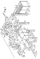
- the embodiment shown in Fig. 1 has a first Heat exchanger 1 and a second heat exchanger 2 connected in series in the fresh air flow direction 3.
- the fresh air is fed in the first heat exchanger 1 through the pipe 4. After passing through the first heat exchanger 1, it arrives at the second heat exchanger 2 and there into the manifold 5 for heated fresh air.
- Several fresh air lines 6 for heated fresh air branch off from this collecting line 5. Each of these lines 6 leads to the fresh air inlet of one or more fermentation tanks, not shown in FIG. 1.
- Exhaust air lines lead from these fermentation containers to the exhaust air collecting line 7, in which a flow divider 8 is provided.
- the flow divider 8 consists of two connections 9, 10 to which two exhaust air partial flow lines 31, 32 are connected.
- Each of the exhaust air partial flow lines leads to one of the two heat exchangers 1, 2, which are designed as air-air heat exchangers.
- the fresh air enters through the fresh air line 41. It is conveyed by the fresh air blower 42 into the fresh air supply line 43, 44 and from there reaches the first heat exchanger 1 in the fresh air supply direction 3 via the pipe 4.
- a further line 45 which connects the exhaust air collecting line 7 to the input of the further air-water heat exchanger 34, serves to bridge the heat exchangers 1, 2, that is to say to bypass.
- this normally closed line 45 is opened, the exhaust air is fed directly to the air-water heat exchanger 34 and cooled by it without heating the fresh air.
- the further line 46 connects the outlet of the air-water heat exchanger 34 to the fresh air supply line 41.
- the further line 47 connects the line 46 to a blower 48, to which the line 49 connects, which leads to the fresh air line (pressure side) 44 .
- Line 50 branches off from line 49 to exhaust air line 38. A portion of the exhaust air can be supplied to the fresh air coming from line 41 via line 46. The mixture of fresh air and exhaust air then passes via line 47 and the blower 48 into line 49, from where it is fed to the fresh air line (pressure side) 44.
- the line 50 serves to admix fresh air to the exhaust air.
- the fresh air passes from line 41 via line 47 into the blower 48 and from there via line 49 into line 50, from where it is mixed with the exhaust air in line 38.
- the line 61 represents the input of the first heat exchanger 1.
- the exhaust air supplied via the line 31 has a temperature of 80 ° C.
- the fresh air supplied via line 4 has a temperature of 10 ° C.
- the temperature profile shown in area 62 is created.
- the exhaust air temperature drops to 50 ° C, while the fresh air temperature rises to 40 ° C.
- the fresh air therefore leaves the first heat exchanger 1 at 40 ° C. and enters the heat exchanger 2 at this temperature.
- Lines 63 and 64 in FIG. 2 represent the output of the first heat exchanger 1 and the input of the second heat exchanger 2, respectively.
- the second partial flow of the exhaust air enters via line 32 at a temperature of 80 ° C. Furthermore, the fresh air which has already been heated to 40 ° C. by the first heat exchanger enters the second heat exchanger 2.
- the temperature curve shown in area 65 takes place in the second heat exchanger.
- the exhaust air cools down to 60 ° C, the supply air, which has already been heated to 40 ° C, also continues to heat up to 60 ° C.
- Line 66 represents the outlet of the second heat exchanger 2.
- the fresh air leaves this second heat exchanger 2 at 60 ° C and enters the fresh air manifold 5.
- the exhaust air also leaves the second heat exchanger 2 at 60 ° C. Both partial exhaust air streams emerging from the two heat exchangers 1 and 2 are combined in the exhaust air line 33.
- FIG. 3 shows a closed fermentation container 21 for holding the organic substances to be processed, that is to say the rotting mixture 71.
- the rotting mixture 71 lies on a floor 11 provided with through-openings, below which there is a fresh air channel 36.
- Above the composting mixture 71 is the free space 72, to which the upper end wall of the container 21 connects.
- the exhaust air opening 22 In the upper end wall 73 there is the exhaust air opening 22, to which the exhaust air pipe 23 connects. It leads via a filter 24 and an outlet connection 25 into an exhaust air pipe 74, which is connected to the exhaust air manifold 7 in FIG. 1.
- the fresh air supply pipe 75 is connected to the fresh air manifold 6 or the fresh air supply lines 6 in FIG. 1.
- the heated fresh air passes from the fresh air manifold 5 via the fresh air lines 6 into the fresh air supply line 75. From there it flows in the direction of the arrow 28 into the pressure blower 27. The fresh air is therefore from this Druckge blower 27 into the fresh air channel 36 and pressed from there through the openings in the bottom 11 into the rotting mixture 71.
- a suction blower 76 is located above the exhaust air opening 22 in the exhaust air pipe 23. The air flow path through the rotting mixture is indicated by the arrows 77.
- the rotting mixture 71 is located on the suction side of the suction fan 76, the exhaust air line 74, through which the exhaust air flows in the direction of the arrow 77, is located on its pressure side.
Landscapes
- Chemical & Material Sciences (AREA)
- Engineering & Computer Science (AREA)
- Microbiology (AREA)
- Life Sciences & Earth Sciences (AREA)
- Biochemistry (AREA)
- Biotechnology (AREA)
- Chemical Kinetics & Catalysis (AREA)
- General Chemical & Material Sciences (AREA)
- Health & Medical Sciences (AREA)
- Molecular Biology (AREA)
- Organic Chemistry (AREA)
- Physics & Mathematics (AREA)
- Thermal Sciences (AREA)
- Combustion & Propulsion (AREA)
- Mechanical Engineering (AREA)
- General Engineering & Computer Science (AREA)
- Fertilizers (AREA)
- Processing Of Solid Wastes (AREA)
- Preparation Of Compounds By Using Micro-Organisms (AREA)
Abstract
Description
Die Erfindung betrifft ein Verfahren zur aeroben, fermentativen Hydrolyse, insbesondere zur Kompostierung von organischen Stoffen in einem geschlossenen Behälter, bei dem den organischen Stoffen Frischluft zugeführt und die mit Wärme und Feuchtigkeit beladene Abluft abgeführt und gekühlt wird, wobei die Wärme der Abluft durch einen Wärmetauscher auf die zugeführte Frischluft übertragen wird. Weiterhin betrifft die Erfindung eine Vorrichtung zur Durchführung eines derartigen Verfahrens, bestehend aus einem geschlossenen Fermentationsbehälter zur Aufnahme der zu verarbeitenden organischen Stoffe mit einer Frischluftzuführung und einer Abluftabführung und einem Wärmetauscher, in dem die Wärme der Abluft an die Frischluft abgebbar ist.The invention relates to a method for aerobic, fermentative hydrolysis, in particular for composting organic substances in a closed container, in which fresh air is supplied to the organic substances and the exhaust air laden with heat and moisture is removed and cooled, the heat of the exhaust air being passed through a heat exchanger is transferred to the fresh air supplied. Furthermore, the invention relates to a device for performing such a method, consisting of a closed fermentation container for receiving the organic substances to be processed with a fresh air supply and an exhaust air discharge and a heat exchanger in which the heat of the exhaust air can be given off to the fresh air.
Ein derartiges Verfahren ist aus der DE-OS 38 11 399 bekannt. Die Frischluft wird vor der Zuführung zu den organischen Stoffen erwärmt, was eine Energieeinsparung mit sich bringt. Die Abluft wird gekühlt und vorzugsweise kondensiert, um die Geruchsbelastung zu vermindern.Such a method is known from DE-OS 38 11 399. The fresh air is heated before being fed to the organic substances, which results in energy savings. The exhaust air is cooled and preferably condensed in order to reduce odor pollution.
Aufgabe der Erfindung ist es, bei einem Verfahren und einer Vorrichtung der oben angegebenen Art die Stoffwechselbedingungen zu verbessern.The object of the invention is to improve the metabolic conditions in a method and a device of the type specified above.
Bei einem Verfahren der eingangs angegebenen Art wird diese Auf gabe dadurch gelöst, daß die Abluft in mindestens zwei Teilströme aufgeteilt wird, daß die Wärme des ersten Abluftstroms durch einen ersten Wärmetauscher auf die zugeführte Frischluft übertragen wird und daß die Wärme des zweiten Abluftstroms durch einen zweiten Wärmetauscher auf die den ersten Wärmetauscher verlassende, durch diesen erwärmte Frischluft übertragen wird.In a method of the type specified at the beginning, this solved in that the exhaust air is divided into at least two partial streams, that the heat of the first exhaust air stream is transferred to the fresh air supplied through a first heat exchanger and that the heat of the second exhaust air stream is transferred through a second heat exchanger to those leaving the first heat exchanger heated fresh air is transmitted.
Bei einer Vorrichtung der eingangs angegebenen Art wird diese Aufgabe gelöst durch einen in der Abluftabführung vorgesehenen Stromteiler zur Teilung des Abluftstromes in mindestens zwei Teilströme und einen zweiten Wärmetauscher, der in Frischluftströmungsrichtung hinter den ersten Wärmetauscher in Reihe geschaltet ist, wobei jedem Wärmetauscher ein Abluft-Teilstrom zuführbar ist.In a device of the type specified at the outset, this object is achieved by a flow divider provided in the exhaust air discharge for dividing the exhaust air flow into at least two partial flows and a second heat exchanger which is connected in series behind the first heat exchanger in the fresh air flow direction, with each heat exchanger having an exhaust air partial flow is feedable.
Die Verwendung von Kompost aus organischen Abfällen setzt eine sichere Entseuchung, d.h. Abtötung von krankheitserregenden Keimen voraus. Krankheitserregende Keime können für Menschen, Tiere und Pflanzen gefährlich sein und müssen daher durch eine geeignete Behandlung während der Kompostierung der Abfälle vernichtet, d.h. in einen lebensunfähigen Zustand überführt werden.The use of compost from organic waste implies safe disinfection, i.e. Killing pathogenic germs ahead. Pathogens can be dangerous for humans, animals and plants and must therefore be destroyed by appropriate treatment during composting of the waste, i.e. be brought into a non-viable state.
Es ist bekannt, daß dieser Zustand dann erreicht wird, wenn lebensfähige Zellen durch Erhöhung der Umgebungstemperatur oder durch antibiotisch wirkende Stoffe zerstört werden. Es ist daher wünschenswert, die Umgebungstemperatur in den organischen Stoffen zu erhöhen.It is known that this state is achieved when viable cells are destroyed by increasing the ambient temperature or by antibiotic substances. It is therefore desirable to raise the ambient temperature in the organics.
Nach der vorliegenden Erfindung wird dies dadurch erreicht, daß die Temperatur der zugeführten Frischluft erhöht wird. Um eine hohe Luftaustrittstemperatur der Frischluft zu erreichen, wird eine zweistufige Erwärmung der Frischluft durchgeführt. Dabei tritt die in der ersten Stufe vom ersten Wärmetauscher vorer wärmte Frischluft in einen nachgeschalteten, zweiten Wärmetauscher ein, der auch als Nacherhitzer bezeichnet werden kann. Der zweite Wärmetauscher wird von einem Abluft-Parallelstrom bzw. Abluft-Teilstrom der gleich hohen Temperatur wie bei der ersten Stufe bzw. dem ersten Wärmetauscher durchströmt. Die hierdurch bewirkte Erhöhung der Frischlufttemperatur führt nun zu einer so hohen Frischluft-Eintrittstemperatur in die organischen Stoffe (Rottegemisch), daß bereits am Boden und in den Randzonen des Rottegemischs Umgebungstemperaturen erreicht werden, bei denen krankheitserregende Keime lebensunfähig werden. Die Stoffwechselbedingungen in den organischen Stoffen werden also entscheidend verbessert. Mit dem erfindungsgemäßen Verfahren und der erfindungsgemäßen Vorrichtung ist es möglich, ohne die Zuführung von Fremdwärmeenergie die gesamte zu kompostierende Masse im Inneren der organischen Stoffe und in allen Randzonen (Boden-, Seiten- und Deckschichten) in einem Vorgang während der Intensivrotte zu entseuchen. Die während des aeroben Stoffwechsels stehende Wasserdampfenergie, die mit der durchgesetzten Luft bzw. Abluft aus dem Rottegemisch abgeführt wird, wird über die Wärmetauscher auf die Zuluft übertragen. Durch das erfindungsgemäße Verfahren und die erfindungsgemäße Vorrichtung wird es also ermöglicht, die Rottefrischluft ohne Fremdwärmezuführung auf Entseuchungstemperatur zu erwärmen. Dies wird dadurch erreicht, daß parallel geschaltete Abluftströme bzw. Abluft-Teilströme über in Frischluftströmungsrichtung in Reihe geschaltete Wärmetauscher geleitet werden.According to the present invention, this is achieved in that the temperature of the fresh air supplied is increased. In order to achieve a high fresh air outlet temperature, the fresh air is heated in two stages. In the first stage, the first heat exchanger occurs warmed fresh air into a downstream, second heat exchanger, which can also be referred to as a reheater. An exhaust air parallel flow or exhaust air partial flow of the same temperature as in the first stage or the first heat exchanger flows through the second heat exchanger. The resulting increase in the fresh air temperature now leads to such a high fresh air inlet temperature in the organic matter (rotting mixture) that ambient temperatures are already reached at the bottom and in the peripheral zones of the rotting mixture, at which pathogenic germs become inoperable. The metabolic conditions in the organic substances are thus decisively improved. With the method according to the invention and the device according to the invention, it is possible to disinfect the entire mass to be composted inside the organic matter and in all peripheral zones (bottom, side and top layers) in one process during intensive rotting without the supply of external heat energy. The water vapor energy which is present during the aerobic metabolism and which is discharged from the rotting mixture with the air or exhaust air which is passed through is transferred to the supply air via the heat exchangers. The method and the device according to the invention thus make it possible to heat the rotting fresh air to the decontamination temperature without supplying external heat. This is achieved in that exhaust air streams connected in parallel or partial exhaust air streams are passed over heat exchangers connected in series in the fresh air flow direction.
Die Höchsttemperatur in der Abluft wird durch die mikrobiologische Stoffwechselaktivität in den organischen Stoffen selbsttätig geregelt. Wenn die Temperatur zu hoch wird, stellen auch jene Formen bzw. Mikroorganismen ihre Stoffwechseltätigkeit ein, die relativ hohe Temperaturen von beispielsweise über 70 bis 80° C noch schadlos überstehen. Die Folge davon ist, daß die Temperatur bei gleicher Luftmenge gleichbleibt oder absinkt.The maximum temperature in the exhaust air is automatically regulated by the microbiological metabolic activity in the organic substances. If the temperature becomes too high, those forms or microorganisms cease their metabolic activity that survive relatively high temperatures of, for example, over 70 to 80 ° C without damage. The consequence of this is that the temperature remains the same or drops with the same amount of air.
Vorteilhafte Weiterbildungen sind in den Unteransprüchen beschrieben.Advantageous further developments are described in the subclaims.
Es können noch weitere, in Frischluftströmungsrichtung in Reihe geschaltete Wärmetauscher vorgesehen sein. Jedem dieser Wärmetauscher wird ein Abluft-Teilstrom zugeführt, wobei diese Abluft-Teilströme parallel geschaltet sind.Further heat exchangers connected in series in the fresh air flow direction can also be provided. An exhaust air partial flow is fed to each of these heat exchangers, these exhaust air partial flows being connected in parallel.
Die Wärmetauscher sind vorzugsweise Luft-Luft-Wärmetauscher.The heat exchangers are preferably air-air heat exchangers.
Vorzugsweise sind die Wärmetauscher derart vorgesehen und dimensioniert, daß die Feuchtigkeit der Abluft auskondensiert wird. Die nahezu vollständige Übertragung der Enthalpie biologisch freigesetzter Dämpfe auf die Zuluft und die damit verbundene Abkühlung der Abluft führen dazu, daß dampfförmige Geruchsstoffe und sonstige Stoffe durch Kondensation abgeschieden werden. Die Geruchsstoffe werden aus der Abluft entfernt, so daß sie die Atmosphäre nicht belasten.The heat exchangers are preferably provided and dimensioned such that the moisture in the exhaust air is condensed out. The almost complete transfer of the enthalpy of biologically released vapors to the supply air and the associated cooling of the exhaust air mean that vaporous odorous substances and other substances are separated out by condensation. The odorous substances are removed from the exhaust air so that they do not pollute the atmosphere.
Nach einer weiteren vorteilhaften Weiterbildung wird die Abluft durch ein Wasserbad, vorzugsweise das Kondensat, geleitet. Da die Luft hierbei zumindest teilweise durch die Kondensatflüssigkeit hindurchtritt, entsteht ein Wascheffekt.According to a further advantageous development, the exhaust air is passed through a water bath, preferably the condensate. Since the air at least partially passes through the condensate liquid, a washing effect occurs.
Da die Austrittstemperatur der Abluft aus den Wärmetauschern bzw. Luft-Luft-Wärmetauschern noch relativ hoch ist und sie damit unter Umständen zumindest teilweise noch kondensierbare Stoffwechselprodukte enthält, kann sie nach einer vorteilhaften Weiterbildung der Erfindung nochmals über einen weiteren Wärmetauscher geleitet werden, der in Strömungsrichtung hinter den oben angegebenen Wärmetauschern liegt. Dieser weitere Wärmetauscher ist vorzugsweise ein Luft-Wasser-Wärmetauscher. Vorzugsweise wird die Kühlwassertemperatur dieses weiteren Wärme tauschers bzw. Luft-Wasser-Wärmetauschers so gewählt, daß alle kondensierbaren Bestandteile der Abluft auskondensieren. Diese auskondensierten Bestandteile können dann in flüssiger Form abgeleitet und ggf. nachbehandelt werden.Since the outlet temperature of the exhaust air from the heat exchangers or air-air heat exchangers is still relatively high and, under certain circumstances, it may at least partially contain condensable metabolic products, according to an advantageous development of the invention, it can again be passed through a further heat exchanger in the direction of flow is behind the heat exchangers specified above. This further heat exchanger is preferably an air-water heat exchanger. Preferably the cooling water temperature of this further heat exchanger or air-water heat exchanger selected so that all condensable components of the exhaust air condense out. These condensed components can then be derived in liquid form and, if necessary, aftertreated.
Bewährt hat sich weiterhin die Nachschaltung eines sorptiv wirkenden Festbettfilters, beispielsweise mit Kompostfüllung, und/oder einer Gaswaschanlage für nicht kondensierbare Bestandteile der Abluft.The connection of a fixed bed filter with a sorptive effect, for example with compost filling, and / or a gas washing system for non-condensable components of the exhaust air has also proven useful.
Die Erfindung betrifft weiterhin ein Verfahren zur aeroben, fermentativen Hydrolyse, insbesondere zur Kompostierung von organischen Stoffen in einem geschlossenen Behälter, bei dem den organischen Stoffen mit Überdruck, vorzugsweise durch ein Druckgebläse, Frischluft zugeführt und die mit Wärme und Feuchtigkeit beladene Abluft abgeführt wird, sowie eine Vorrichtung zur Durchführung eines derartigen Verfahrens, bestehend aus einem geschlossenen Fermentationsbehälter zur Aufnahme der zu verarbeitenden organischen Stoffe mit einer Frischluftzuführung und einer Abluftabführung und einem in der Frischluftzuführung vorgesehenen Druckgebläse.The invention further relates to a method for aerobic, fermentative hydrolysis, in particular for composting organic substances in a closed container, in which fresh air is supplied to the organic substances with overpressure, preferably by means of a pressure blower, and the exhaust air laden with heat and moisture is removed, and a device for performing such a method, consisting of a closed fermentation container for receiving the organic substances to be processed with a fresh air supply and an exhaust air discharge and a pressure blower provided in the fresh air supply.
Ein derartiges Verfahren und eine derartige Vorrichtung sind aus der DE-PS 36 37 393 bekannt. Die Frischluft wird den organischen Stoffen durch ein Druckgebläse zugeführt. Unter den organischen Stoffen befindet sich ein mit Öffnungen versehener Boden, unter dem Luftzuführungskanäle angeordnet sind. Diesen Luftzuführungskanälen wird die Frischluft durch das Druckgebläse zugeführt. Die Frischluft durchströmt die Öffnungen in dem Boden und durchströmt anschließend die organischen Stoffe. Über dem Rottegemisch befindet sich in dem geschlossenen Behälter ein mehr oder weniger großer Freiraum. In der oberen Abschlußfläche des geschlossenen Behälters ist ein Abluftöffnung vorgesehen, an die sich die Abluftleitung anschließt.Such a method and such a device are known from DE-PS 36 37 393. The fresh air is supplied to the organic matter by a pressure blower. Under the organic matter there is an apertured floor under which air supply ducts are arranged. The fresh air is supplied to these air supply ducts by the pressure blower. The fresh air flows through the openings in the floor and then flows through the organic substances. There is a more or less large free space above the rotting mixture in the closed container. In the upper end surface of the closed container, an exhaust air opening is provided, to which the exhaust air line connects.
Bei einem Verfahren dieser Art wird die der Erfindung zugrundeliegende Aufgabe, die Stoffwechselbedingungen zu verbessern, dadurch gelöst, daß die Abluft mit Unterdruck, vorzugsweise durch ein Unterdruckgebläse, abgeführt wird. Bei einer Vorrichtung dieser Art wird die der Erfindung zugrundeliegende Aufgabe durch ein in der Abluftabführung vorgesehenes Sauggebläse gelöst.In a method of this type, the object on which the invention is based, to improve the metabolic conditions, is achieved in that the exhaust air is removed with a vacuum, preferably by means of a vacuum blower. In a device of this type, the object on which the invention is based is achieved by a suction fan provided in the exhaust air discharge.
Da für biologisches Leben auch der Wasserdampfpartialdruck und die Substratfeuchte von Bedeutung sind, wird die erfindungsgemäße besondere Schaltung der Belüftungsgebläse vorgesehen. Um einen niedrigen Wasserdampfpartialdruck und damit günstige Stoffwechselbedingungen zu erreichen, werden zwei Gebläse benutzt, die so geschaltet werden, daß ein Gebläse die Luft blasend in das Rottegemisch fördert und das andere Gebläse zunächst, also auf das Rottegemisch, saugend wirkt und die Abluft mit den Stoffwechselprodukten über dem Rottegemisch absaugt. Über dem Rottegemisch entsteht dadurch ein leichter Unterdruck. Diese Betriebsweise hat den weiteren Vorteil, daß der Druck über dem Rottegemisch so gering ist, daß keine Verdichtung des Rottegemischs und damit auch keine Verschlechterung der Luftversorgung eintritt. Wenn das Rottegemisch schon weitgehend abgebaut ist, so daß es trocken wird, ist die Gefahr der Verdichtung nicht mehr so groß. Durch die erfindungsgemäßen Maßnahmen wird in noch kürzerer Zeit biologisch freigesetztes Wasser und/oder Haftwasser verdunstet.Since the water vapor partial pressure and the substrate moisture are also important for biological life, the special switching of the ventilation fans according to the invention is provided. In order to achieve a low water vapor partial pressure and thus favorable metabolic conditions, two blowers are used, which are switched so that one blower blows the air into the rotting mixture and the other blower first, i.e. on the rotting mixture, has a suction effect and the exhaust air with the metabolic products aspirated above the rotting mixture. This creates a slight negative pressure above the rotting mixture. This mode of operation has the further advantage that the pressure above the rotting mixture is so low that there is no compression of the rotting mixture and thus no deterioration in the air supply. If the rotting mixture has largely been broken down so that it becomes dry, the risk of compaction is no longer as great. The measures according to the invention evaporate biologically released water and / or adhesive water in an even shorter time.
Vorteilhafte Weiterbildungen sind in Unteransprüchen beschrieben.Advantageous further developments are described in the subclaims.
Es ist vorteilhaft, wenn die Frischluft den organischen Stoffen von unter zugeführt wird und wenn die Abluft über den organischen Stoffen abgeführt bzw. abgesaugt wird. Das Rottegemisch wird dann von unten nach oben durchströmt.It is advantageous if the fresh air is supplied to the organic substances from below and if the exhaust air is removed or extracted via the organic substances. The rotting mix is then flowed through from bottom to top.
Vorzugsweise hat das saugende Gebläse ungefähr die gleiche Leistung wie das drückende Gebläse.Preferably, the suction blower has approximately the same performance as the push blower.
Durch Parallelschaltung der Gebläse kann die Luftdurchsatzleistung entsprechend erhöht werden. Die Leistungen beider Gebläse sind dann stets gut aufeinander abgestimmt.The air throughput can be increased accordingly by connecting the fans in parallel. The performance of both fans is always well coordinated.
Besonders vorteilhaft ist es, wenn die beiden oben beschriebenen Verfahren, für die selbständig Schutz beansprucht wird, miteinander kombiniert werden. In gleicher Weise ist es besonders vorteilhaft, wenn die beiden oben beschriebenen Vorrichtungen, für die ebenfalls selbständig Schutz beansprucht wird, miteinander kombiniert werden.It is particularly advantageous if the two methods described above, for which protection is claimed independently, are combined with one another. In the same way, it is particularly advantageous if the two devices described above, for which protection is also claimed independently, are combined with one another.
Ein Ausführungsbeispiel der Erfindung wird nachstehend anhand der beigefügten Zeichnung im einzelnen beschrieben. In der Zeichnung zeigt
- Fig. 1 zwei in Frischluftströmungsrichtung in Reihe geschaltete Luft-Luft-Wärmetauscher mit zugehörigem Leitungssystem in einer isometrischen Darstellung,
- Fig. 2 die Temperatur im Frischluftstrom und in zwei parallelen Abluftströmen in einer schematischen Darstellung und
- Fig. 3 einen geschlossenen Fermentationsbehälter mit Druckgebläse und Unterdruckgebläse in einer Schnittdarstellung.
- 1 is an isometric view of two air-air heat exchangers connected in series in the fresh air flow direction, with an associated line system,
- Fig. 2 shows the temperature in the fresh air flow and in two parallel exhaust air flows in a schematic representation
- Fig. 3 shows a closed fermentation tank with pressure blower and vacuum blower in a sectional view.
Das in Fig. 1 gezeigte Ausführungsbeispiel besitzt einen ersten Wärmetauscher 1 und einen in Frischluftströmungsrichtung 3 dahinter liegenden, in Reihe geschalteten zweiten Wärmetauscher 2. Die Frischluft wird im ersten Wärmetauscher 1 durch das Rohr 4 zugeführt. Sie gelangt nach Durchlaufen des ersten Wärmetauschers 1 zum zweiten Wärmetauscher 2 und dort in die Sammelleitung 5 für erwärmte Frischluft. Von dieser Sammelleitung 5 zweigen mehrere Frischluftleitungen 6 für erwärmte Frischluft ab. Jede dieser Leitungen 6 führt zum Frischlufteingang eines oder mehrerer, in Fig. 1 nicht gezeigter Fermentationsbehälter.The embodiment shown in Fig. 1 has a
Von diesen Fermentationsbehältern führen Abluftleitungen zur Abluft-Sammelleitung 7, in der ein Stromteiler 8 vorgesehen ist. Der Stromteiler 8 besteht aus zwei Anschlüssen 9, 10, an die sich zwei Abluft-Teilstromleitungen 31, 32 anschließen. Jede der Abluft-Teilstromleitungen führt zu einem der beiden Wärmetauscher 1, 2, die als Luft-Luft-Wärmetauscher ausgebildet sind.Exhaust air lines lead from these fermentation containers to the exhaust air collecting line 7, in which a flow divider 8 is provided. The flow divider 8 consists of two
Am Abluft-Ausgang der Wärmetauscher 1, 2 befindet sich die Leitung 33 für abgekühlte Abluft. An diese schließt sich ein weiterer Luft-Wasser-Wärmetauscher 34 an, dessen Ausgang mit der Abluftleitung 37, 38 verbunden ist. Am Ende der Abluftleitung 38 befindet sich das sorptiv wirkende Festbett-Filter 39, das von unten nach oben durchströmt wird und von dem gefilterte, gekühlte Abluft in Richtung des Pfeiles 40 austritt.At the exhaust air outlet of the
Die Frischluft tritt durch die Frischluftleitung 41 ein. Sie wird durch das Frischluftgebläse 42 in die Frischluft-Zuleitung 43, 44 gefördert und gelangt von dort in Frischluft-Zuführrichtung 3 über das Rohr 4 in den ersten Wärmetauscher 1.The fresh air enters through the fresh air line 41. It is conveyed by the
Eine weitere Leitung 45, die die Abluft-Sammelleitung 7 mit dem Eingang des weiteren Luft-Wasser-Wärmetauschers 34 verbindet, dient dazu, die Wärmetauscher 1, 2 zu überbrücken, also zu umgehen. Wenn diese normalerweise geschlossene Leitung 45 geöffnet wird, wird die Abluft ohne Erwärmung der Frischluft unmittelbar dem Luft-Wasser-Wärmetauscher 34 zugeführt und von diesem abgekühlt.A
Die weitere Leitung 46 verbindet den Ausgang des Luft-Wasser-Wärmetauschers 34 mit der Frischluft-Zuführleitung 41. Die weitere Leitung 47 verbindet die Leitung 46 mit einem Gebläse 48, an das sich die Leitung 49 anschließt, die zur Frischluftleitung (druckseitig) 44 führt. Von der Leitung 49 zweigt die Leitung 50 zur Abluftleitung 38 ab. Über die Leitung 46 kann ein Teil der Abluft der von der Leitung 41 kommenden Frischluft zugeführt werden. Das Gemisch aus Frischluft und Abluft gelangt dann über die Leitung 47 und das Gebläse 48 in die Leitung 49, von wo es der Frischluftleitung (druckseitig) 44 zugeführt wird.The
Die Leitung 50 dient zur Zumischung von Frischluft zur Abluft. Die Frischluft gelangt von der Leitung 41 über die Leitung 47 in das Gebläse 48 und von dort über die Leitung 49 in die Leitung 50, von wo sie der Abluft in der Leitung 38 zugemischt wird.The
Die Fig. 2 zeigt den Temperaturverlauf der Zuluft und der Abluft in den Wärmetauschern 1 und 2. Die Linie 61 repräsentiert den Eingang des ersten Wärmetauschers 1. In dem gewählten Ausführungsbeispiel hat dort die über die Leitung 31 zugeführte Abluft eine Temperatur von 80° C und die über die Leitung 4 zugeführte Frischluft eine Temperatur von 10° C. Im ersten Wärmetauscher (erste Stufe) entsteht der im Bereich 62 dargestellte Temperaturverlauf. Die Ablufttemperatur sinkt auf 50° C ab, während die Frischlufttemperatur auf 40° C ansteigt. Die Frischluft verläßt also den ersten Wärmetauscher 1 mit 40° C und tritt mit dieser Temperatur in den Wärmetauscher 2 ein. Die Linien 63 und 64 in Fig. 2 repräsentieren den Ausgang des ersten Wärmetauschers 1 bzw. den Eingang des zweiten Wärmetauschers 2.2 shows the temperature profile of the supply air and the exhaust air in the
In dem zweiten Wärmetauscher 2 tritt der zweite Teilstrom der Abluft über die Leitung 32 mit einer Temperatur von 80° C ein. Weiterhin tritt in den zweiten Wärmetauscher 2 die bereits vom ersten Wärmetauscher auf 40° C erwärmte Frischluft ein. Im zweiten Wärmetauscher findet der im Bereich 65 gezeigte Temperaturverlauf statt. Die Abluft kühlt sich auf 60° C ab, die bereits auf 40° C erwärmte Zuluft erwärmt sich noch weiter auf ebenfalls 60° C. Die Linie 66 repräsentiert den Ausgang des zweiten Wärmetauschers 2. Die Frischluft verläßt diesen zweiten Wärmetauscher 2 mit 60° C und tritt in die Frischluft-Sammelleitung 5 ein. Auch die Abluft verläßt den zweiten Wärmetauscher 2 mit 60° C. Beide Abluft-Teilströme, die aus den beiden Wärmetauschern 1 und 2 austreten, werden in der Abluftleitung 33 zusammengefaßt.In the
Die Fig. 3 zeigt einen geschlossenen Fermentationsbehälter 21 zur Aufnahme der zu verarbeitenden organischen Stoffe, also des Rottegemischs 71. Das Rottegemisch 71 liegt auf einem mit Durchtrittsöffnungen versehenen Boden 11 auf, unter dem sich ein Frischluftkanal 36 befindet. Über dem Rottegemisch 71 befindet sich der Freiraum 72, an den sich die obere Endwand des Behälters 21 anschließt. In der oberen Endwand 73 befindet sich die Abluftöffnung 22, an die sich das Abluftrohr 23 anschließt. Es führt über einen Filter 24 und einen Austrittsstutzen 25 in ein Abluftrohr 74, welches an die Abluft-Sammelleitung 7 in Fig. 1 angeschlossen ist. Das Frischluft-Zuführrohr 75 ist an die Frischluft-Sammelleitung 6 bzw. die Frischluft-Zuführleitungen 6 in Fig. 1 angeschlossen.FIG. 3 shows a
Die erwärmte Frischluft gelangt von der Frischluft-Sammelleitung 5 über die Frischluft-Leitungen 6 in die Frischluft-Zuführleitung 75. Sie strömt von dort in Richtung des Pfeiles 28 in das Druckgebläse 27. Die Frischluft wird also von diesem Druckge bläse 27 in den Frischluftkanal 36 und von dort über die Öffnungen in dem Boden 11 in das Rottegemisch 71 hineingedrückt. Oberhalb der Abluftöffnung 22 befindet sich in dem Abluftrohr 23 ein Sauggebläse 76. Der Luftströmungsverlauf durch das Rottegemisch wird durch die Pfeile 77 angedeutet. Das Rottegemisch 71 befindet sich auf der Saugseite des Sauggebläses 76, die Abluftleitung 74, die von der Abluft in Richtung des Pfeiles 77 durchströmt wird, befindet sich auf dessen Druckseite.The heated fresh air passes from the fresh air manifold 5 via the fresh air lines 6 into the fresh
Claims (22)
bei dem den organischen Stoffen (71) Frischluft zugeführt und die mit Wärme und Feuchtigkeit beladene Abluft abgeführt und gekühlt wird,
wobei die Wärme der Abluft durch einen Wärmetauscher (1) auf die zugeführte Frischluft übertragen wird,
dadurch gekennzeichnet,
daß die Abluft in mindestens zwei Teilströme (31, 32) aufgeteilt wird
daß die Wärme des ersten Abluftstroms durch einen ersten Wärmetauscher (1) auf die zugeführte Frischluft übertragen wird
und daß die Wärme des zweiten Abluftstroms (32) durch einen zweiten Wärmetauscher (2) auf die den ersten Wärmetauscher (1) verlassende, durch diesen erwärmte Frischluft übertragen wird.1. A method for aerobic, fermentative hydrolysis, in particular for composting organic substances (71) in a closed container (21),
in which fresh air is supplied to the organic substances (71) and the exhaust air laden with heat and moisture is removed and cooled,
the heat of the exhaust air being transferred to the fresh air supplied through a heat exchanger (1),
characterized,
that the exhaust air is divided into at least two partial flows (31, 32)
that the heat of the first exhaust air stream is transferred to the fresh air supplied through a first heat exchanger (1)
and that the heat of the second exhaust air flow (32) is transferred through a second heat exchanger (2) to the fresh air leaving the first heat exchanger (1) and heated by the latter.
einem geschlossenen Fermentationsbehälter (21) zur Aufnahme der zu verarbeitenden organischen Stoffe (71) mit einer Frischluftzuführung (5, 75) und einer Abluftabführung (74, 7)
und einem Wärmetauscher (1), in dem die Wärme der Abluft an die Frischluft abgebbar ist,
gekennzeichnet durch
einen in der Abluftabführung (7) vorgesehen Stromteiler (8) zur Teilung des Abluftstromes in mindestens zwei Teilströme (31, 32)
und einen zweiten Wärmetauscher (2), der in Frischluftströmungsrichtung (3) hinter dem ersten Wärmetauscher (1) in Reihe geschaltet ist,
wobei jedem Wärmetauscher (1, 2) ein Abluft-Teilstrom (31, 32) zuführbar ist.9. Device for performing the method according to one of claims 1 to 8, consisting of
a closed fermentation container (21) for receiving the organic substances to be processed (71) with a fresh air supply (5, 75) and an exhaust air discharge (74, 7)
and a heat exchanger (1) in which the heat of the exhaust air can be given off to the fresh air,
marked by
a flow divider (8) provided in the exhaust air discharge (7) for dividing the exhaust air flow into at least two partial flows (31, 32)
and a second heat exchanger (2) which is connected in series in the fresh air flow direction (3) behind the first heat exchanger (1),
An exhaust air partial flow (31, 32) can be fed to each heat exchanger (1, 2).
dadurch gekennzeichnet,
daß die Abluft mit Unterdruck, vorzugsweise durch ein Unterdruckgebläse (76), abgeführt wird.14. A method for aerobic, fermentative hydrolysis, in particular for composting organic substances (71) in a closed container (21), in which the organic substances (71) are supplied with fresh air, preferably by means of a pressure blower (27), and with Exhaust air laden with heat and moisture is removed,
characterized,
that the exhaust air is removed with vacuum, preferably by a vacuum blower (76).
einem geschlossenen Fermentationsbehälter (21) zur Aufnahme der zu verarbeitenden organischen Stoffe (71) mit einer Frischluftzuführung (75) und einer Abluftabführung (23, 74)
und einem in der Frischluftzuführung (75) vorgesehenen Druckgebläse (27),
gekennzeichnet durch
ein in der Abluftabführung (23) vorgesehenes Sauggebläse (76).18. Device for performing the method according to one of claims 14 to 17, consisting of
a closed fermentation container (21) for receiving the organic substances to be processed (71) with a fresh air supply (75) and an exhaust air discharge (23, 74)
and a pressure blower (27) provided in the fresh air supply (75),
marked by
a suction fan (76) provided in the exhaust air outlet (23).
Applications Claiming Priority (2)
| Application Number | Priority Date | Filing Date | Title |
|---|---|---|---|
| DE3925905 | 1989-08-04 | ||
| DE19893925905 DE3925905A1 (en) | 1989-08-04 | 1989-08-04 | METHOD AND DEVICE FOR AEROBIC, FERMENTATIVE HYDROLYSIS, IN PARTICULAR FOR COMPOSTING ORGANIC SUBSTANCES |
Publications (3)
| Publication Number | Publication Date |
|---|---|
| EP0413992A2 true EP0413992A2 (en) | 1991-02-27 |
| EP0413992A3 EP0413992A3 (en) | 1991-08-14 |
| EP0413992B1 EP0413992B1 (en) | 1994-06-15 |
Family
ID=6386557
Family Applications (1)
| Application Number | Title | Priority Date | Filing Date |
|---|---|---|---|
| EP19900114499 Expired - Lifetime EP0413992B1 (en) | 1989-08-04 | 1990-07-27 | Process and apparatus for aerobic, fermentative hydrolysis, particularly for composting of organic materials |
Country Status (3)
| Country | Link |
|---|---|
| EP (1) | EP0413992B1 (en) |
| AT (1) | ATE107268T1 (en) |
| DE (2) | DE3925905A1 (en) |
Cited By (6)
| Publication number | Priority date | Publication date | Assignee | Title |
|---|---|---|---|---|
| WO1993023351A1 (en) * | 1992-05-09 | 1993-11-25 | Klaus Grabbe | Composting device with several separate reactors and one central ventilation device |
| WO1993023350A1 (en) * | 1992-05-09 | 1993-11-25 | Klaus Grabbe | Composting device with a ventilation system for closed rotting devices |
| WO1994027932A1 (en) * | 1993-05-25 | 1994-12-08 | Innosepe Oy | Method for composting solid organic material and a composter for applying said method |
| WO1997022842A3 (en) * | 1995-12-18 | 1997-08-14 | Ml Entsorgungs Und Energieanla | Process and device for drying organic waste |
| FR2896243A1 (en) * | 2006-01-13 | 2007-07-20 | Vinci Environnement Soc Par Ac | PROCESS FOR COMPOSTING OR STABILIZING ORGANIC MATERIALS AND INSTALLATION FOR CARRYING OUT SAID METHOD |
| CN112934918A (en) * | 2021-02-04 | 2021-06-11 | 智旅环保科技(上海)有限公司 | Safe biological digestion method for kitchen wet garbage |
Families Citing this family (1)
| Publication number | Priority date | Publication date | Assignee | Title |
|---|---|---|---|---|
| CN110903110A (en) * | 2019-11-25 | 2020-03-24 | 浙江万泰环境工程有限公司 | Quick good oxygen system of becoming fertile of natural pond sediment |
Citations (2)
| Publication number | Priority date | Publication date | Assignee | Title |
|---|---|---|---|---|
| DE3811399A1 (en) * | 1987-04-03 | 1988-10-13 | Hermann Hofmann | Process for the aerobic fermentative hydrolysis, in particular composting, of organic substances and apparatus for carrying out this process |
| GB2214910A (en) * | 1987-12-11 | 1989-09-13 | Green Land Ltd | Apparatus and a method for preparing composts |
-
1989
- 1989-08-04 DE DE19893925905 patent/DE3925905A1/en not_active Withdrawn
-
1990
- 1990-07-27 DE DE59006119T patent/DE59006119D1/en not_active Expired - Fee Related
- 1990-07-27 EP EP19900114499 patent/EP0413992B1/en not_active Expired - Lifetime
- 1990-07-27 AT AT90114499T patent/ATE107268T1/en not_active IP Right Cessation
Patent Citations (2)
| Publication number | Priority date | Publication date | Assignee | Title |
|---|---|---|---|---|
| DE3811399A1 (en) * | 1987-04-03 | 1988-10-13 | Hermann Hofmann | Process for the aerobic fermentative hydrolysis, in particular composting, of organic substances and apparatus for carrying out this process |
| GB2214910A (en) * | 1987-12-11 | 1989-09-13 | Green Land Ltd | Apparatus and a method for preparing composts |
Cited By (8)
| Publication number | Priority date | Publication date | Assignee | Title |
|---|---|---|---|---|
| WO1993023351A1 (en) * | 1992-05-09 | 1993-11-25 | Klaus Grabbe | Composting device with several separate reactors and one central ventilation device |
| WO1993023350A1 (en) * | 1992-05-09 | 1993-11-25 | Klaus Grabbe | Composting device with a ventilation system for closed rotting devices |
| US5693528A (en) * | 1992-05-09 | 1997-12-02 | Grabbe; Klaus | Composting unit having a ventilation system for closed rotting units |
| WO1994027932A1 (en) * | 1993-05-25 | 1994-12-08 | Innosepe Oy | Method for composting solid organic material and a composter for applying said method |
| WO1997022842A3 (en) * | 1995-12-18 | 1997-08-14 | Ml Entsorgungs Und Energieanla | Process and device for drying organic waste |
| FR2896243A1 (en) * | 2006-01-13 | 2007-07-20 | Vinci Environnement Soc Par Ac | PROCESS FOR COMPOSTING OR STABILIZING ORGANIC MATERIALS AND INSTALLATION FOR CARRYING OUT SAID METHOD |
| EP1808425A3 (en) * | 2006-01-13 | 2010-07-21 | Vinci Environnement | Method of composting or stabilising organic matter and installation for implementing said method |
| CN112934918A (en) * | 2021-02-04 | 2021-06-11 | 智旅环保科技(上海)有限公司 | Safe biological digestion method for kitchen wet garbage |
Also Published As
| Publication number | Publication date |
|---|---|
| EP0413992A3 (en) | 1991-08-14 |
| DE59006119D1 (en) | 1994-07-21 |
| DE3925905A1 (en) | 1991-02-28 |
| ATE107268T1 (en) | 1994-07-15 |
| EP0413992B1 (en) | 1994-06-15 |
Similar Documents
| Publication | Publication Date | Title |
|---|---|---|
| EP0322424B1 (en) | Process for composting organic material and device for carrying out this process | |
| WO2008095685A2 (en) | Apparatus and method for drying fermentation residues | |
| EP1363855B1 (en) | Method and device for treating liquids | |
| EP3066187B1 (en) | Device and method for drying fermentation residues | |
| DE112020005882T5 (en) | INTEGRATED MATERIAL DRYING AND COOLING MACHINE | |
| EP1064954A1 (en) | Steam steriliser | |
| EP0458221B1 (en) | Process for drying sludge | |
| DE3637700A1 (en) | METHOD FOR REGENERATING A DRYING CARTRIDGE LOADED WITH MOISTURE AND DEVICE FOR CARRYING OUT SUCH A METHOD | |
| EP0705791A1 (en) | Process and apparatus for obtaining nitrogen | |
| EP0413992B1 (en) | Process and apparatus for aerobic, fermentative hydrolysis, particularly for composting of organic materials | |
| WO2003050046A1 (en) | Method and device for drying sludge, particularly sewage sludge | |
| DE4208390A1 (en) | Compost exhaust air cooling, used for e.g. for organic, domestic waste - comprises transferring heat from exhaust to feed air through air-air heat exchanger, which is fed with liq., e.g. water, etc. | |
| CH645333A5 (en) | Moist composting process for organic waste materials, for example sewage sludge, and apparatus for carrying out the process | |
| DE3603985C2 (en) | ||
| DE102007053212A1 (en) | Drying of solid portions from the separation of fermentation remainders of a biogas plant and/or of liquid manure, comprises supplying an exhaust gas flow into a drying mechanism having the solid portions, and drying the solid portions | |
| DE3522890C2 (en) | Device and method for generating sterile air | |
| EP0545214A2 (en) | Process for waste air purification from oil-mill plants | |
| DE4422855C1 (en) | Waste composting plant | |
| DE19513262C1 (en) | Process for composting organic matter, especially waste | |
| DE4300188C2 (en) | Method and device for the rapid composting of decomposable material | |
| DE202007019055U1 (en) | Drying plant for drying a solid fraction from the solid-liquid separation of a dispersion containing biological material | |
| EP0422509B1 (en) | Method for degasing plants | |
| AT403549B (en) | METHOD FOR PURIFYING EXHAUST AIR AND EXHAUST AIR PURIFICATION SYSTEM | |
| DE2837892C2 (en) | Device for condensing steam | |
| DE10125408A1 (en) | Treatment of municipal waste comprises removing recyclable materials, mechanically grinding and sieving remaining material and mixing medium with part of fermenter, product being fermented to produce biogas used to generate electricity |
Legal Events
| Date | Code | Title | Description |
|---|---|---|---|
| PUAI | Public reference made under article 153(3) epc to a published international application that has entered the european phase |
Free format text: ORIGINAL CODE: 0009012 |
|
| AK | Designated contracting states |
Kind code of ref document: A2 Designated state(s): AT DE IT |
|
| PUAL | Search report despatched |
Free format text: ORIGINAL CODE: 0009013 |
|
| AK | Designated contracting states |
Kind code of ref document: A3 Designated state(s): AT DE IT |
|
| 17P | Request for examination filed |
Effective date: 19920117 |
|
| 17Q | First examination report despatched |
Effective date: 19921113 |
|
| GRAA | (expected) grant |
Free format text: ORIGINAL CODE: 0009210 |
|
| AK | Designated contracting states |
Kind code of ref document: B1 Designated state(s): AT DE IT |
|
| PG25 | Lapsed in a contracting state [announced via postgrant information from national office to epo] |
Ref country code: IT Free format text: LAPSE BECAUSE OF FAILURE TO SUBMIT A TRANSLATION OF THE DESCRIPTION OR TO PAY THE FEE WITHIN THE PRE;WARNING: LAPSES OF ITALIAN PATENTS WITH EFFECTIVE DATE BEFORE 2007 MAY HAVE OCCURRED AT ANY TIME BEFORE 2007. THE CORRECT EFFECTIVE DATE MAY BE DIFFERENT FROM THE ONE RECORDED.SCRIBED TIME-LIMIT Effective date: 19940615 |
|
| REF | Corresponds to: |
Ref document number: 107268 Country of ref document: AT Date of ref document: 19940715 Kind code of ref document: T |
|
| REF | Corresponds to: |
Ref document number: 59006119 Country of ref document: DE Date of ref document: 19940721 |
|
| PLBE | No opposition filed within time limit |
Free format text: ORIGINAL CODE: 0009261 |
|
| STAA | Information on the status of an ep patent application or granted ep patent |
Free format text: STATUS: NO OPPOSITION FILED WITHIN TIME LIMIT |
|
| 26N | No opposition filed | ||
| PGFP | Annual fee paid to national office [announced via postgrant information from national office to epo] |
Ref country code: AT Payment date: 19960705 Year of fee payment: 7 |
|
| PGFP | Annual fee paid to national office [announced via postgrant information from national office to epo] |
Ref country code: DE Payment date: 19960730 Year of fee payment: 7 |
|
| PG25 | Lapsed in a contracting state [announced via postgrant information from national office to epo] |
Ref country code: AT Free format text: LAPSE BECAUSE OF NON-PAYMENT OF DUE FEES Effective date: 19970727 |
|
| PG25 | Lapsed in a contracting state [announced via postgrant information from national office to epo] |
Ref country code: DE Free format text: LAPSE BECAUSE OF NON-PAYMENT OF DUE FEES Effective date: 19980401 |