EP0415691A1 - Cap device for a bag-in-box type container - Google Patents
Cap device for a bag-in-box type container Download PDFInfo
- Publication number
- EP0415691A1 EP0415691A1 EP19900309365 EP90309365A EP0415691A1 EP 0415691 A1 EP0415691 A1 EP 0415691A1 EP 19900309365 EP19900309365 EP 19900309365 EP 90309365 A EP90309365 A EP 90309365A EP 0415691 A1 EP0415691 A1 EP 0415691A1
- Authority
- EP
- European Patent Office
- Prior art keywords
- film member
- mouthpiece
- inner hollow
- container
- cap device
- Prior art date
- Legal status (The legal status is an assumption and is not a legal conclusion. Google has not performed a legal analysis and makes no representation as to the accuracy of the status listed.)
- Granted
Links
Images


Classifications
-
- B—PERFORMING OPERATIONS; TRANSPORTING
- B65—CONVEYING; PACKING; STORING; HANDLING THIN OR FILAMENTARY MATERIAL
- B65D—CONTAINERS FOR STORAGE OR TRANSPORT OF ARTICLES OR MATERIALS, e.g. BAGS, BARRELS, BOTTLES, BOXES, CANS, CARTONS, CRATES, DRUMS, JARS, TANKS, HOPPERS, FORWARDING CONTAINERS; ACCESSORIES, CLOSURES, OR FITTINGS THEREFOR; PACKAGING ELEMENTS; PACKAGES
- B65D75/00—Packages comprising articles or materials partially or wholly enclosed in strips, sheets, blanks, tubes, or webs of flexible sheet material, e.g. in folded wrappers
- B65D75/38—Articles or materials enclosed in two or more wrappers disposed one inside the other
-
- B—PERFORMING OPERATIONS; TRANSPORTING
- B65—CONVEYING; PACKING; STORING; HANDLING THIN OR FILAMENTARY MATERIAL
- B65B—MACHINES, APPARATUS OR DEVICES FOR, OR METHODS OF, PACKAGING ARTICLES OR MATERIALS; UNPACKING
- B65B7/00—Closing containers or receptacles after filling
- B65B7/16—Closing semi-rigid or rigid containers or receptacles not deformed by, or not taking-up shape of, contents, e.g. boxes or cartons
- B65B7/28—Closing semi-rigid or rigid containers or receptacles not deformed by, or not taking-up shape of, contents, e.g. boxes or cartons by applying separate preformed closures, e.g. lids, covers
- B65B7/2842—Securing closures on containers
- B65B7/2878—Securing closures on containers by heat-sealing
-
- B—PERFORMING OPERATIONS; TRANSPORTING
- B65—CONVEYING; PACKING; STORING; HANDLING THIN OR FILAMENTARY MATERIAL
- B65D—CONTAINERS FOR STORAGE OR TRANSPORT OF ARTICLES OR MATERIALS, e.g. BAGS, BARRELS, BOTTLES, BOXES, CANS, CARTONS, CRATES, DRUMS, JARS, TANKS, HOPPERS, FORWARDING CONTAINERS; ACCESSORIES, CLOSURES, OR FITTINGS THEREFOR; PACKAGING ELEMENTS; PACKAGES
- B65D47/00—Closures with filling and discharging, or with discharging, devices
- B65D47/04—Closures with discharging devices other than pumps
- B65D47/20—Closures with discharging devices other than pumps comprising hand-operated members for controlling discharge
-
- B—PERFORMING OPERATIONS; TRANSPORTING
- B65—CONVEYING; PACKING; STORING; HANDLING THIN OR FILAMENTARY MATERIAL
- B65D—CONTAINERS FOR STORAGE OR TRANSPORT OF ARTICLES OR MATERIALS, e.g. BAGS, BARRELS, BOTTLES, BOXES, CANS, CARTONS, CRATES, DRUMS, JARS, TANKS, HOPPERS, FORWARDING CONTAINERS; ACCESSORIES, CLOSURES, OR FITTINGS THEREFOR; PACKAGING ELEMENTS; PACKAGES
- B65D51/00—Closures not otherwise provided for
- B65D51/18—Arrangements of closures with protective outer cap-like covers or of two or more co-operating closures
- B65D51/20—Caps, lids, or covers co-operating with an inner closure arranged to be opened by piercing, cutting, or tearing
-
- B—PERFORMING OPERATIONS; TRANSPORTING
- B65—CONVEYING; PACKING; STORING; HANDLING THIN OR FILAMENTARY MATERIAL
- B65D—CONTAINERS FOR STORAGE OR TRANSPORT OF ARTICLES OR MATERIALS, e.g. BAGS, BARRELS, BOTTLES, BOXES, CANS, CARTONS, CRATES, DRUMS, JARS, TANKS, HOPPERS, FORWARDING CONTAINERS; ACCESSORIES, CLOSURES, OR FITTINGS THEREFOR; PACKAGING ELEMENTS; PACKAGES
- B65D75/00—Packages comprising articles or materials partially or wholly enclosed in strips, sheets, blanks, tubes, or webs of flexible sheet material, e.g. in folded wrappers
- B65D75/52—Details
- B65D75/58—Opening or contents-removing devices added or incorporated during package manufacture
- B65D75/5861—Spouts
- B65D75/5872—Non-integral spouts
- B65D75/5877—Non-integral spouts connected to a planar surface of the package wall
-
- B—PERFORMING OPERATIONS; TRANSPORTING
- B67—OPENING, CLOSING OR CLEANING BOTTLES, JARS OR SIMILAR CONTAINERS; LIQUID HANDLING
- B67D—DISPENSING, DELIVERING OR TRANSFERRING LIQUIDS, NOT OTHERWISE PROVIDED FOR
- B67D1/00—Apparatus or devices for dispensing beverages on draught
- B67D1/04—Apparatus utilising compressed air or other gas acting directly or indirectly on beverages in storage containers
- B67D1/0462—Squeezing collapsible or flexible beverage containers, e.g. bag-in-box containers
-
- B—PERFORMING OPERATIONS; TRANSPORTING
- B65—CONVEYING; PACKING; STORING; HANDLING THIN OR FILAMENTARY MATERIAL
- B65D—CONTAINERS FOR STORAGE OR TRANSPORT OF ARTICLES OR MATERIALS, e.g. BAGS, BARRELS, BOTTLES, BOXES, CANS, CARTONS, CRATES, DRUMS, JARS, TANKS, HOPPERS, FORWARDING CONTAINERS; ACCESSORIES, CLOSURES, OR FITTINGS THEREFOR; PACKAGING ELEMENTS; PACKAGES
- B65D2251/00—Details relating to container closures
- B65D2251/0003—Two or more closures
- B65D2251/0006—Upper closure
- B65D2251/0015—Upper closure of the 41-type
-
- B—PERFORMING OPERATIONS; TRANSPORTING
- B65—CONVEYING; PACKING; STORING; HANDLING THIN OR FILAMENTARY MATERIAL
- B65D—CONTAINERS FOR STORAGE OR TRANSPORT OF ARTICLES OR MATERIALS, e.g. BAGS, BARRELS, BOTTLES, BOXES, CANS, CARTONS, CRATES, DRUMS, JARS, TANKS, HOPPERS, FORWARDING CONTAINERS; ACCESSORIES, CLOSURES, OR FITTINGS THEREFOR; PACKAGING ELEMENTS; PACKAGES
- B65D2251/00—Details relating to container closures
- B65D2251/0003—Two or more closures
- B65D2251/0068—Lower closure
- B65D2251/0093—Membrane
-
- Y—GENERAL TAGGING OF NEW TECHNOLOGICAL DEVELOPMENTS; GENERAL TAGGING OF CROSS-SECTIONAL TECHNOLOGIES SPANNING OVER SEVERAL SECTIONS OF THE IPC; TECHNICAL SUBJECTS COVERED BY FORMER USPC CROSS-REFERENCE ART COLLECTIONS [XRACs] AND DIGESTS
- Y10—TECHNICAL SUBJECTS COVERED BY FORMER USPC
- Y10T—TECHNICAL SUBJECTS COVERED BY FORMER US CLASSIFICATION
- Y10T137/00—Fluid handling
- Y10T137/8593—Systems
- Y10T137/87917—Flow path with serial valves and/or closures
- Y10T137/88054—Direct response normally closed valve limits direction of flow
Definitions
- This invention relates to a cap device for sealing a mouthpiece of a container such as a bag-in-box which is required to have sterilizing ability and methods of sealing a mouthpiece portion of the container by utilizing the cap device and opening the same.
- a container which is required to be hermetically sealed and, as one example of the container of this character, is known so-called a bag-in-box of the type in which a foldable plastic bag container is accommodated in a corrugated fiberboard box for an outer package so as to utilize the box as a container suitable for conveying and reserving liquid content.
- the bag-in-box container and the cap device are subjected to sterilizing treatment (for example, irradiation of ⁇ -ray) beforehand.
- sterilizing treatment for example, irradiation of ⁇ -ray
- a certain conventional cap device for the container such as bag-in-box is provided with a function as a connector.
- Such cap device is provided with a connector member to which a coupling member is connected to thereby form a dispenser means (external connection line) for optionally taking out the content in the bag-in-box.
- a dispenser means external connection line
- the bag-in-box container of this type it is also required to be provided with the sterilization maintaining property.
- the connector member of the mouthpiece of the conventional cap device is, in general, sealed by one valve member. Therefore, when the dispenser means is assembled by connecting the coupling member to the connector member as described above, the content in the bag-in-box is always communicated with contaminated portions of the connector member and the coupling member.
- the insufficient control of the dispenser means to microorganisms may be resulted, in an adverse case, in the degradation of the content or food poisoning for a person.
- An object of this invention is to substantially eliminate the defects and drawbacks encountered to the prior art described above and to provide cap devices to be mounted to mouthpiece portions of containers and methods of sealing and opening the mouthpiece capable of maintaining suitable sterilized and sanitary condition of the mouthpiece portion during the connection of the cap device and the usage thereof.
- a cap device to be mounted to a mouthpiece of a container, comprising a cap member provided with an inner hollow portion and a film member accommodated in the inner hollow portion of the cap member, the cap member being provided with a projection formed on an inner surface thereof and projecting inwardly of the inner hollow portion for temporarily supporting the film member in the inner hollow portion to prevent the film member from falling therefrom and the film member comprising a layered structure composed of at least one metal including layer and a fusing layer abutting against an open end face of the mouthpiece mounted to the container.
- a cap device to be mounted to a mouthpiece of a container, comprising a connecting portion to be connected to the mouthpiece of the container, the connecting portion being provided with an inner hollow portion, a coupling projecting portion formed integrally with the connecting portion and adapted to be connected to an external connection line, the coupling projecting portion being provided with an axial through hole communicated with the inner hollow portion of the connecting portion, and a movable valve member disposed in the axial through hole to be axially movable.
- the movable valve member comprises a first seal member for sealing one end of the through hole of the coupling projecting portion, a second seal member for sealing the other end of the through hole and an elastic member disposed between the first and second seal members for outwardly urging the first and second seal members.
- a cap device to be mounted to a mouthpiece of a container, comprising a connecting portion provided with an inner hollow portion to be connected to the mouthpiece of the container, a coupling projecting portion integrally connected to the connecting portion and adapted to be connected to an external connection line, the coupling projecting portion being provided with an inner axial through hole communicated with the inner hollow portion of the connecting portion, a film member accommodated in the inner hollow portion of the connecting portion, and a movable valve member accommodated in the through hole of the coupling projecting portion to be axially expandable and shrinkable, the film member having a layered structure composed of two fusing layers constituting inner and outer layers of the film member and at least one metal including layer disposed between the two fusing layers.
- a method of sealing a mouthpiece of a container by a cap device comprising a cap member provided with an inner hollow portion and a film member accommodated in the inner hollow portion of the cap member, the film member having a layered structure composed of a fusing layer abutting against an opening end face of the mouthpiece of the container and at least one metal including layer and the cap member being provided with a projection formed on an inner surface thereof and projecting inwardly of the inner hollow portion for temporarily supporting the film member in the inner hollow portion, the method being characterized by comprising the steps of mounting the cap device to the mouthpiece of the container with the film member being accommodated in the inner hollow portion of the cap member, heating the film member by means of high frequency induction heating to heat the metal including layer and fuse the fusing layer and sealing the open end face of the mouthpiece of the container with the fused fusing layer.
- a method of opening a mouthpiece of a container from a cap device, after sealing the same comprising a cap member provided with an inner hollow portion and a film member accommodated in the inner hollow portion of the cap member, the film member having a layered structure composed of a fusing layer abutting against an open end face of the mouthpiece of the container and at least one metal including layer and the cap member being provided with a projection formed on an inner surface thereof and projecting inwardly of the inner hollow portion for temporarily supporting the film member in the inner hollow portion, the method being characterized by comprising the steps of removing a cap member, connecting a connection line to the mouthpiece portion and applying a pressure to the film member from either one of outer and inner sides of the container to break the film member to thereby establish communication betweeen an interior of the container and the connection line without being exposed to an atmosphere.
- a method of opening a mouthpiece of a container from a cap device, after sealing the same comprising a cap member provided with an inner hollow portion and a film member accommodated in the inner hollow portion of the cap member, the film member having a layered structure composed of a fusing layer abutting against an open end face of the mouthpiece of the container and at least one metal including layer and the cap member being provided with a projection formed on an inner surface thereof and projecting inwardly of the inner hollow portion for temporarily supporting the film member in the inner hollow portion, the method being characterized by comprising the steps of preparing a connector having a cutter and a connection line, removing the cap member, connecting the connector to the mouthpiece of the container so that the cutter is directed to the film member, connecting the connection line to an outer end of the connector, projecting the cutter towards the film member to break the film member to thereby establish communication between an interior of the container and the connection line without being exposed to an atmosphere.
- a method of sealing a mouthpiece of a container by a cap device comprising a connecting portion provided with an inner hollow portion to be connected to the mouthpiece of the container, a coupling projecting portion integrally connected to the connecting portion and adapted to be connected to an external connection line, the coupling projection portion being provided with an inner axial through hole communicated with the inner hollow portion of the connecting portion and a film member accommodated in the inner hollow portion of the connecting portion, the film member having a layered structure composed of two fusing layers constituting inner and outer layers of the film member and at least one metal including layer disposed between the two fusing layers, the method being characterized by comprising the steps of mounting the cap device to the mouthpiece of the container with the film member being accommodated in the inner hollow portion of the connecting portion, heating the film member by means of high frequency induction heating to heat the metal including layer and fuse the fusing layers to an open end face of the mouthpiece and a top portion of the inner hollow portion of
- a method of opening a mouthpiece of a container from a cap device, after sealing the same comprising a connecting portion provided with an inner hollow portion to be connected to the mouthpiece of the container, a coupling projecting portion integrally connected to the connecting portion and adapted to be connected to an external connection line, the coupling projecting portion being provided with an inner axial through hole communicated with the inner hollow portion of the connecting portion, a film member accommodated in the hollow portion of the connecting portion, and a movable valve member accommodated in the through hole of the coupling projecting portion to be axially expandable and shrinkable, the film member having a layered structure composed of two fusing layers constituting inner and outer layers of the film member and at least one metal including layer disposed between the two fusing layers, the method being characterized by comprising the steps of preparing a connector having an inner hollow portion in which a projecting pin is provided, connecting a connector to an outer end portion of the coupling projecting portion so that the pin extend
- the cap device to be mounted to the mouthpiece portion of a container preferably a bag-in-box container
- the mouthpiece portion can be easily sealed and opened without being exposed to the atmosphere, thus being sanitory and the content can be easily taken out.
- the connection line can also be connected to the cap device under the sterilized condition.
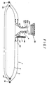
- Fig. 1 shows a sectional view of a cap device 20, as the first embodiment of this invention, in a condition before the sealing of the cap device to a bag-in-box 1 provided with a connection mouthpiece 4.
- the bag-in-box 1 is formed as a double-bag structure comprising an inner bag 2 and an outer bag 3 enclosing the inner bag 2, and the connection mouthpiece 4 of unitary structure for filling and taking out a content in and from the inner bag 2.
- connection mouthpiece 4 comprises a cylindrical mouthpiece body 45, a lower flanged portion 46 as an adhesive portion for the inner bag 2 and an upper flanged portion 47 as an adhesive portion for the outer bag 3, the lower and upper flanged portions 46 and 47 being integrally formed to the lower and upper portions of the mouthpiece body 45.
- Two projections 45a and 45b in form of threads are formed to a portion near the periphery of the upper end of the mouthpiece body 45.
- the mouthpiece body 45 is provided with a base portion from which a connection plug 48 is projected upwardly as viewed.
- the mouthpiece body 45 is also provided with an axial opening having relatively large diameter and communicating with an interior of the inner bag 2.
- the opening constitutes a communication hole 10 with respect to the inner bag 2 for filling the content into the inner bag 2 or taking out the content therefrom.
- Another hole having relatively small diameter is bored in the connection plug 48 and the mouthpiece body 45 so as to form a communication hole 11 with respect to the outer bag 3.
- the inner and outer bags 2 and 3 are formed of a plastic film material such as polyethlene by forming the plastic film materials into multi-cylindrical portions having slightly mutually different inner diameters and the both open end portions of the cylindrical portions are heat fused by a heat sealer, for example, to form seal portions 2a and 3a, thus forming the plastic film materials into double bag structure.
- a plastic film material such as polyethlene
- the attachment of the mouthpiece 4 to the inner and outer bags 2 and 3 are performed by first forming holes to the film materials of the inner and outer bags 2 and 3 in vertical alignment, inserting the lower portion of the mouthpiece body 45 into these holes and then heat fusing the lower and upper flanged portions 46 and 47 of the lower portion of the mouthpiece body 45 to the film materials of the inner and outer bags 2 and 3.
- the film member 21 is, of a disk-shape having flexibility and is directly contacted to an open end face 45c of the mouthpiece 4 as described hereunder.
- the film member 21, as shown in Fig. 3, has a laminated structure, for example, three-layered structure comprising a supporting layer 21a, a metal including layer 21b and a fusing layer 21c with the metal including layer 21b being interposed between the other two layers 21a and 21c.
- the metal including layer 21b may be formed of an aluminum foil having a thickness of about 30 ⁇ m or a material made by blending metal particles into resin material.
- the metal including layer 21b attains its function when the film member 21 is subjected to high frequency fusing treatment.
- Fig. 6 is an enlarged sectional view of the cap device 50 according to the second embodiment before the mounting to the mouthpiece 4.
- the cap device 50 comprises a connection portion J to be connected to the mouthpiece 4 of the bag-in-box container and a coupling portion P formed integrally with the connection portion J so as to extend upwardly as viewed.
- the film member 121 is not limited to the three-layered structure and, in an alternation, the film member 121 may be formed to have laminated structure having more than four layers by interposing other intermediate layers as occasion demands.
- a recess g2 having a shape of linear cutout groove for example, in a portion of the flat surface of the film member 121 (it is preferred to form the recess g2 without cutting the fusing layer 121c) for providing a suitable seal opening function.
- the fusing layers 121a and 121c may be cutout without cutting out the metal including layer 121b and, in such a case, substantially identical preferable effect may be attained.
- the first seal member 60 comprises a sealing portion 61 having a predetermined curved surface suitable for attaining the abut-sealing function to the valve seat 56 formed as a stepped portion at one end portion of the through hole C end a base portion 63 provided with a cylindrical slidable portion 64 integrally projecting from the sealing portion 61.
- a flanged portion 62 is integrally formed to the sealing portion 61.
- Figs. 10 and 11 represent modifications of the movable valve member utilized for the cap device 50 of the second embodiment of this invention.
- the first seal member 200 of substantially spherical shape comprises an outer sealing portion 201 to seal the through hole C in abutment against one end thereof formed as a stepped portion and an inner engaging portion 202 so as to abut against one end 220a of the coil spring 220.
- the second seal member 210 of substantially spherical shape comprises an outer sealing portion 211 to seal the through hole C in abutment against the other end thereof formed as a stepped portion and an inner engaging portion 212 so as to abut against the other end 220b of the coil spring 220.
- the sealing surface is formed to be spherical, the improved sealing effect can be attained. It is desired to form a ring-shaped projection 213 on the peripheral surface of the second seal member 210 as shown in Fig. 10 for the purpose of achieving accurate abutting engagement with the engaging portion 52 of the through hole C.
- the elastic material for the movable valve member shown in fig. 11 is utilized a various kind of elastomers such as natural rubber, synthetic rubber or plastic material having elasticity. It is desired as shown in Fig. 11 to disposed a rigid disk-shaped washer 95 to the neck portion of the second sealing portion 70a for achieving the firm abutting engagement with the engaging portion 52 of the through hole C.
- the cap device 20 having the cap member 25 having the inner hollow portion in which the film member 21 is accommodated is first prepared.
- the cap device 20 is fitted to the mouthpiece 4 of the bag-in-box container 1 so as to maintain the inner sealed condition from the outer atmosphere by the locations of two projections 45a and 45b formed on the outer periphery of the mouthpiece 4 and the two projections 25a and 25b formed on the inner periphery of the inner hollow portion of the cap member 25.
- the sterilizing process by use of ⁇ -ray, for example, is performed.
- the cap device 20 is separated from the mouthpiece 4 by mechanical means, not shown, while maintaining the sterilized condition, and a sterilized nozzle member N is press connected to the mouthpiece 4 to fill the inner bag 2 with liquid such as sirup.
- the cap device 20 is again fitted to the mouthpiece 4 as shown in Fig. 12D.
- the cap device 20 is moved to a station directly below a head H of a high frequency induction heating coil and the film member 21 disposed inside the cap device 20 is fused to the open end face 45c of the mouthpiece 4 by passing current through the high frequency induction heating coil having the head H which is lowered and pressed against the cap device 20 as shown in Fig. 12E.
- the metal including layer 21b of the film member 21 is heated by the high frequency heating treatment and accordingly the fusing layer 21c having a low melting point is fused hermetically to the open end opening face 45c of the mouthpiece 4.
- a pressure is additionally applied to the bag-in-box and a pressure is also applied to the film member 21, thus establishing the communication between the interior of the bag-in-box and the connector L without being exposed to the atmosphere, thus being sanitary.
- the liquid content in the bag-in-box can be taken out in the sterilized condition without being exposed to the atmosphere.
- the grooved cutout g1 As described hereinbefore, for this seal opening and content take-out method, it is desired to preliminarily form the grooved cutout g1, as shown in Fig. 4, in the flat surface portion of the film member 21.
- the grooved cutout g1 may be formed by the irradiation of laser beam, for example.
- a connector 100 to which a cutter blade 75 is equipped is connected to the mouthpiece 4 and a conduit line 110 is connected to the rear portion, upper portion as viewed, of the connector 100.
- the cutter blade 75 is projected forwardly, downwardly as viewed, by pushing the rear end 77a of a shaft 77 supporting the cutter blade 75, thereby breaking the film member 21 and establishing the communication between the interior of the bag-in-box and the conduit line 110.
- the adoption of the cap device and the sealing and seal opening methods according to this invention make it possible to communicate the interior of the bag-in-box with the connector under the completely sterilized condition.
- the bag-in-box can be hermetically connected to the connector in the sterilized condition, the sterilized condition of the connector line can be also maintained, thus achieving the remarkable effects in comparison with the prior art technique, particularly as the countermeasure to the microorganism.
- the frequency of the sterilizing processes can be remarkably reduced during the feeding or taking out of the content such as drink solution in comparison with the prior art technique, thus making it possible to simplify the sanitary system and sterilizing working.
- the sanitation operation has been carried out every or every other day in the prior art technique, but, according to this invention, it was found that the sterilized condition can be effectively maintained by carrying out the sanitation operation every one or two weeks.
- the basic principle of the method of mounting the cap device 50 represented by Figs. 14A to 14E is substantially identical to that of the method of mounting the cap device 20 of the first embodiment represented by Figs. 12A to 12F and the respective steps represented by Figs. 14A to 14E substantially correspond to the steps represented by Figs. 12A to 12E.
- the difference of the method of Fig. 14 from the method of Fig. 12 resides in that both surfaces of the film member 121 are fused respectively to the open end face 45c of the mothpiece 4 and to the top surface 125c of the inner hollow portion E3 of the cap device 50 to thereby integrate the cap device 50 and the mouthpiece 4 through the film member 121.
- the film member 121 is broken by a liquid pressure caused by the applicatin of the pressure applied to the bag-in-box, whereby the communication between the interior of the bag-in-box, and the connection couduit line can be achieved without being exposed to the atmosphere.
- cap device 50 of the second embodiment The function or operation of the cap device 50 of the second embodiment at a time when the inner liquid such as sirup is taken out from the bag-in-box will be explained hereunder.
- the sealing condition of the cap device 50 becomes to the state shown in Fig. 15. Since the interior of the bag-in-box is shut out from the connection conduit line by the first sealing member 60 during this operation, the content in the bag-in-box is not contaminated. Accordingly, in a time when the content is not taken out from the bag-in-box, the end portion of the through hole C on the side of the bag-in-box is always sealed by the first sealing member 60.
Landscapes
- Engineering & Computer Science (AREA)
- Mechanical Engineering (AREA)
- Packages (AREA)
- Closures For Containers (AREA)
Abstract
Description
- This invention relates to a cap device for sealing a mouthpiece of a container such as a bag-in-box which is required to have sterilizing ability and methods of sealing a mouthpiece portion of the container by utilizing the cap device and opening the same.
- There is known a container which is required to be hermetically sealed and, as one example of the container of this character, is known so-called a bag-in-box of the type in which a foldable plastic bag container is accommodated in a corrugated fiberboard box for an outer package so as to utilize the box as a container suitable for conveying and reserving liquid content.
- It is important to keep the sterilized condition for drink liquid and chemical liquid in a case where such liquids are fed into the bag-in-box of the character described above. In addition, for such a bag-in-box, it is also required to be easily used and handled. Accordingly, the bag-in-box container and the cap device are subjected to sterilizing treatment (for example, irradiation of γ-ray) beforehand. Many improvements for the structure of the cap device have been made for this purpose. However, almost all existing cap devices are constructed as single unit caps.
- In the prior technique, in the actual usage of the bag-in-box container which is filled up with liquid under sterilized condition, a cap is manually removed and a mouth portion of the bag-in-box is then connected to a take-out jig such as a connector to take out the liquid in the bag-in-box. Accordingly, a mouthpiece of the bag-in-box container is temporarily directly exposed to an outer atmosphere at a time of being connected to the connector and there may cause a case where the outer atmosphere is intruded into the bag-in-box container or air of a head space in the container is flown out.
- In view of the maintenance of the sterilization of the bag-in-box, it is not desired that the mouth portion is directly exposed to the outer atmosphere even in temporarily and many technical attempts have been tried to eliminate this problem.
- A certain conventional cap device for the container such as bag-in-box is provided with a function as a connector. Such cap device is provided with a connector member to which a coupling member is connected to thereby form a dispenser means (external connection line) for optionally taking out the content in the bag-in-box. For the bag-in-box container of this type, it is also required to be provided with the sterilization maintaining property.
- However, the connector member of the mouthpiece of the conventional cap device is, in general, sealed by one valve member. Therefore, when the dispenser means is assembled by connecting the coupling member to the connector member as described above, the content in the bag-in-box is always communicated with contaminated portions of the connector member and the coupling member.
- The insufficient control of the dispenser means to microorganisms may be resulted, in an adverse case, in the degradation of the content or food poisoning for a person.
- An object of this invention is to substantially eliminate the defects and drawbacks encountered to the prior art described above and to provide cap devices to be mounted to mouthpiece portions of containers and methods of sealing and opening the mouthpiece capable of maintaining suitable sterilized and sanitary condition of the mouthpiece portion during the connection of the cap device and the usage thereof.
- This and other object can be achieved according to this invention, in one aspect, by providing a cap device to be mounted to a mouthpiece of a container, comprising a cap member provided with an inner hollow portion and a film member accommodated in the inner hollow portion of the cap member, the cap member being provided with a projection formed on an inner surface thereof and projecting inwardly of the inner hollow portion for temporarily supporting the film member in the inner hollow portion to prevent the film member from falling therefrom and the film member comprising a layered structure composed of at least one metal including layer and a fusing layer abutting against an open end face of the mouthpiece mounted to the container.
- In another aspect of this invention, there is provided a cap device to be mounted to a mouthpiece of a container, comprising a connecting portion to be connected to the mouthpiece of the container, the connecting portion being provided with an inner hollow portion, a coupling projecting portion formed integrally with the connecting portion and adapted to be connected to an external connection line, the coupling projecting portion being provided with an axial through hole communicated with the inner hollow portion of the connecting portion, and a movable valve member disposed in the axial through hole to be axially movable. The movable valve member comprises a first seal member for sealing one end of the through hole of the coupling projecting portion, a second seal member for sealing the other end of the through hole and an elastic member disposed between the first and second seal members for outwardly urging the first and second seal members.
- In a further aspect of this invention, there is provided a cap device to be mounted to a mouthpiece of a container, comprising a connecting portion provided with an inner hollow portion to be connected to the mouthpiece of the container, a coupling projecting portion integrally connected to the connecting portion and adapted to be connected to an external connection line, the coupling projecting portion being provided with an inner axial through hole communicated with the inner hollow portion of the connecting portion, a film member accommodated in the inner hollow portion of the connecting portion, and a movable valve member accommodated in the through hole of the coupling projecting portion to be axially expandable and shrinkable, the film member having a layered structure composed of two fusing layers constituting inner and outer layers of the film member and at least one metal including layer disposed between the two fusing layers.
- In a still further aspect of this invention, there is provided a method of sealing a mouthpiece of a container by a cap device comprising a cap member provided with an inner hollow portion and a film member accommodated in the inner hollow portion of the cap member, the film member having a layered structure composed of a fusing layer abutting against an opening end face of the mouthpiece of the container and at least one metal including layer and the cap member being provided with a projection formed on an inner surface thereof and projecting inwardly of the inner hollow portion for temporarily supporting the film member in the inner hollow portion, the method being characterized by comprising the steps of mounting the cap device to the mouthpiece of the container with the film member being accommodated in the inner hollow portion of the cap member, heating the film member by means of high frequency induction heating to heat the metal including layer and fuse the fusing layer and sealing the open end face of the mouthpiece of the container with the fused fusing layer.
- In a still further aspect of this invention, there is provided a method of opening a mouthpiece of a container from a cap device, after sealing the same, comprising a cap member provided with an inner hollow portion and a film member accommodated in the inner hollow portion of the cap member, the film member having a layered structure composed of a fusing layer abutting against an open end face of the mouthpiece of the container and at least one metal including layer and the cap member being provided with a projection formed on an inner surface thereof and projecting inwardly of the inner hollow portion for temporarily supporting the film member in the inner hollow portion, the method being characterized by comprising the steps of removing a cap member, connecting a connection line to the mouthpiece portion and applying a pressure to the film member from either one of outer and inner sides of the container to break the film member to thereby establish communication betweeen an interior of the container and the connection line without being exposed to an atmosphere.
- In a still further aspect of this invention, there is provided a method of opening a mouthpiece of a container from a cap device, after sealing the same, comprising a cap member provided with an inner hollow portion and a film member accommodated in the inner hollow portion of the cap member, the film member having a layered structure composed of a fusing layer abutting against an open end face of the mouthpiece of the container and at least one metal including layer and the cap member being provided with a projection formed on an inner surface thereof and projecting inwardly of the inner hollow portion for temporarily supporting the film member in the inner hollow portion, the method being characterized by comprising the steps of preparing a connector having a cutter and a connection line, removing the cap member, connecting the connector to the mouthpiece of the container so that the cutter is directed to the film member, connecting the connection line to an outer end of the connector, projecting the cutter towards the film member to break the film member to thereby establish communication between an interior of the container and the connection line without being exposed to an atmosphere.
- In a still further aspect of this invention, there is provided a method of sealing a mouthpiece of a container by a cap device, after sealing the same, comprising a connecting portion provided with an inner hollow portion to be connected to the mouthpiece of the container, a coupling projecting portion integrally connected to the connecting portion and adapted to be connected to an external connection line, the coupling projection portion being provided with an inner axial through hole communicated with the inner hollow portion of the connecting portion and a film member accommodated in the inner hollow portion of the connecting portion, the film member having a layered structure composed of two fusing layers constituting inner and outer layers of the film member and at least one metal including layer disposed between the two fusing layers, the method being characterized by comprising the steps of mounting the cap device to the mouthpiece of the container with the film member being accommodated in the inner hollow portion of the connecting portion, heating the film member by means of high frequency induction heating to heat the metal including layer and fuse the fusing layers to an open end face of the mouthpiece and a top portion of the inner hollow portion of the connecting portion of the cap device and sealing the mouthpiece of the container with the fused fusing layers of the film member.
- In a still further aspect of this invention, there is provided a method of opening a mouthpiece of a container from a cap device, after sealing the same, comprising a connecting portion provided with an inner hollow portion to be connected to the mouthpiece of the container, a coupling projecting portion integrally connected to the connecting portion and adapted to be connected to an external connection line, the coupling projecting portion being provided with an inner axial through hole communicated with the inner hollow portion of the connecting portion, a film member accommodated in the hollow portion of the connecting portion, and a movable valve member accommodated in the through hole of the coupling projecting portion to be axially expandable and shrinkable, the film member having a layered structure composed of two fusing layers constituting inner and outer layers of the film member and at least one metal including layer disposed between the two fusing layers, the method being characterized by comprising the steps of preparing a connector having an inner hollow portion in which a projecting pin is provided, connecting a connector to an outer end portion of the coupling projecting portion so that the pin extends inward of the coupling projecting portion, applying a pressure to one end of the movable valve member by the pin to depress and open the one end thereof, applying a pressure to the film member from either one of outer and inner sides of the container to break the film member and open the other end of the movable member to thereby establish communication between an interior of the container and an outer connection line without being exposed to an atmosphere.
- According to this invention of the characters described above, the cap device to be mounted to the mouthpiece portion of a container, preferably a bag-in-box container, has a structure hermetically mounted to the mouthpiece portion of the container. The mouthpiece portion can be easily sealed and opened without being exposed to the atmosphere, thus being sanitory and the content can be easily taken out. The connection line can also be connected to the cap device under the sterilized condition.
- For a better understanding of this invention and to show how the invention can be carried out, reference will be made, by way of preferred embodiments, to the accompanying drawings, in which:
- Fig. 1 is a longitudinal sectional view of a bag-in-box of double bag structure provided with a mouthpiece and a cap device of the first embodiment of this invention;
- Fig. 2 is a sectional view, in an enlarged scale, of the cap device shown in Fig. 1;
- Figs. 3 and 4 are sectional views showing layered structures of film members to be accommodated in the cap device shown in Fig. 2;
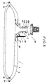
- Fig. 5 is a longitudinal sectional view of a bag-in-box of double bag structure provided with a mouthpiece and a cap device of the second embodiment of this invention
- Fig. 6 is a sectional view, in an enlarged scale, of the cap device shown in Fig. 5;
- Figs. 7 and 8 are sectional views showing layered structures of film members to be accommodated in the cap device shown in Fig. 6;
- Figs. 9A and 9B are plan and sectional views of the second sealing member of the cap device shown in Fig. 6;
- Fig. 10 is a sectional view of a modified example of a movable valve member of the cap device shown in Fig. 6;
- Figs. 11A and 11B are sectional views of another modified example of the movable valve member;
- Figs. 12A to 12F are sectional views of the cap device of the first embodiment for the explanatory of the cap device sealing and opening method in respective steps;
- Fig. 13 is a sectional view of the cap device shown in Fig. 12 showing a condition that the film member is cut out by means of a cutter blade;
- Figs. 14A to 14E are sectional views of the cap device of the second embodiment showing conditions similar to those of Figs. 12A to 12E; and
- Figs. 15 and 16 are sectional views of the cap device of the second embodiment for the explanatory of the operation of the movable valve member.
- This invention will be described in detail hereunder with reference to a cap device to be connected to a mouthpiece of a bag-in-box as one typical example of a cap device for the mouthpiece of a container in which liquid content is contained.
- Fig. 1 shows a sectional view of a
cap device 20, as the first embodiment of this invention, in a condition before the sealing of the cap device to a bag-in-box 1 provided with aconnection mouthpiece 4. - The bag-in-
box 1 is formed as a double-bag structure comprising aninner bag 2 and anouter bag 3 enclosing theinner bag 2, and theconnection mouthpiece 4 of unitary structure for filling and taking out a content in and from theinner bag 2. - In the illustration of Fig. 1, an outer box as an outer package in which the bag-in-
box 1 is accommodated is eliminated for the sake of convenience. - As shown in Fig. 1, the
connection mouthpiece 4 comprises acylindrical mouthpiece body 45, a lowerflanged portion 46 as an adhesive portion for theinner bag 2 and an upper flangedportion 47 as an adhesive portion for theouter bag 3, the lower and upper flangedportions mouthpiece body 45. Twoprojections mouthpiece body 45. - The
mouthpiece body 45 is provided with a base portion from which aconnection plug 48 is projected upwardly as viewed. Themouthpiece body 45 is also provided with an axial opening having relatively large diameter and communicating with an interior of theinner bag 2. The opening constitutes acommunication hole 10 with respect to theinner bag 2 for filling the content into theinner bag 2 or taking out the content therefrom. Another hole having relatively small diameter is bored in theconnection plug 48 and themouthpiece body 45 so as to form acommunication hole 11 with respect to theouter bag 3. - The inner and
outer bags seal portions 2a and 3a, thus forming the plastic film materials into double bag structure. - The attachment of the
mouthpiece 4 to the inner andouter bags outer bags mouthpiece body 45 into these holes and then heat fusing the lower and upper flangedportions mouthpiece body 45 to the film materials of the inner andouter bags - The
cap device 20 of the first embodiment of this invention to be mounted to theconnection mouthpiece 4 of the character described hereinabove will be described hereunder with reference to the accompanying drawings. - Referring to Fig. 2, showing a sectional view of the
cap device 20 before the mounting to themouthpiece 4, thecap device 20 comprises anouter cap member 25 of substantially cylindrical shape having an inner hollow portion E1 and afilm member 21 disposed in the inner hollow portion E1. - The
film member 21 is, of a disk-shape having flexibility and is directly contacted to anopen end face 45c of themouthpiece 4 as described hereunder. - The
film member 21, as shown in Fig. 3, has a laminated structure, for example, three-layered structure comprising a supporting layer 21a, ametal including layer 21b and afusing layer 21c with themetal including layer 21b being interposed between the other twolayers 21a and 21c. - In a preferred example, the
metal including layer 21b may be formed of an aluminum foil having a thickness of about 30 µm or a material made by blending metal particles into resin material. Themetal including layer 21b attains its function when thefilm member 21 is subjected to high frequency fusing treatment. - The supporting layer 21a may be made of a resin material having a flexibility such as polyethylene terephthalate (PET) having a thickness of about 15 µm.
- It is preferred to form the
fusing layer 21c with the same material as that constituting themouthpiece 4 for the reason that thefusing layer 21c is fused to theopen end face 45c of themouthpiece 4. For this reason, thefusing layer 21c may be formed of polyethylene (PE) having thickness of about 45 µm. - The
film member 21 is not limited to the three-layered structure and, in an alternation, the supporting layer 21a may be removed or thefilm member 21 may be formed to have multilayered structures having more than four layers by interposing other intermedicate layers as occasion demands. - As shown in Fig. 4, it may be desired to form a recess g1 having a shape of cutout groove, for example, in a portion of the flat surface of the film member 21 (it is preferred to form the recess g1 without cutting the
fusing layer 21c) for providing a suitable seal opening function as described hereunder. In an alternation, the supporting layer 21a and thefusing layer 21c may be cutout without cutting out themetal including layer 21b. - The cylindrical
outer cap member 25 has twoprojections 25a and 25b projected inwardly of the inner hollow portion E1 so that theflexible film member 21 is disposed temporarily, without being dripped out, in an uppermost space E2 as viewed in the inner hollow portion E1. Namely, since the inner diameter of the upper projection 25a is slightly smaller than the outer diameter of theflexible film member 21, thefilm member 21 forcibly fitted into the space E2 cannot be easily dropped out. - The second embodiment of the cap device provided with a connection means, i.e. connector, according to this invention will be described hereunder with reference to the accompanying drawings.
- Fig. 5 is a sectional view of the bag-in-
box container 1 of double bag structure provided with theconnection mouthpiece 4 and acap device 50, before the sealing, according to the second embodiment of this invention. - Referring to Fig. 5, the structure of the bag-in-
box 1 of this embodiment is substantially the same as that of the first embodiment, so that the details thereof are omitted herein and, accordingly, thecap device 50 to be mounted to themouthpiece 4 of the bag-in-box 1 is now described hereunder. - Fig. 6 is an enlarged sectional view of the
cap device 50 according to the second embodiment before the mounting to themouthpiece 4. Thecap device 50 comprises a connection portion J to be connected to themouthpiece 4 of the bag-in-box container and a coupling portion P formed integrally with the connection portion J so as to extend upwardly as viewed. - The connection portion J is provided with an inner hollow portion E3 into which the
mouthpiece 4 is inserted. In a preferred example, aflexible film member 121 is disposed in the hollow portion E3. The connection portion J is also provided with twoprojections 125a and 125b, for example, so as to project inwardly of the hollow portion E3 as described with reference to the first embodiment as theprojections 25a and 25b, and the disk-shapedflexible film member 121 is temporarily disposed in an uppermost space E4 in the hollow portion E3. Since the inner diameter of the projection 125a is slightly smaller than the outer diameter of theflexible film member 121, thefilm member 121 forcibly inserted into the space E4 cannot be easily dropped out. - As shown in Fig. 7, the
film member 121 has a laminated structure, for example, three-layered structure comprising afusing layer 121a, ametal including layer 121b and afusing layer 121c with themetal including layer 121b being interposed between the other two fusinglayers - In a preferred example, the
metal including layer 121b may be formed of an aluminum foil having a thickness of about 30 um or a material made by blending metal particles into resin material. Themetal including layer 21b attains its function when thefilm member 21 is subjected to high frequency induction heating and fusing treatment as described with reference to the first embodiment. - The fusing layers 121a and 121c abut against the
top surface 125c of the hollow portion E3 (Fig. 6) and theopen end face 45c (Fig. 5) of themouthpiece 4 and both of the layers are heat fused in this state. For this purpose, it is desired to form thefusing layers mouthpiece 4. For this reason, the fusinglayers - The
film member 121 is not limited to the three-layered structure and, in an alternation, thefilm member 121 may be formed to have laminated structure having more than four layers by interposing other intermediate layers as occasion demands. - As shown in Fig. 8 and as described with reference to the first embodiment, it may be desired to form a recess g2 having a shape of linear cutout groove, for example, in a portion of the flat surface of the film member 121 (it is preferred to form the recess g2 without cutting the
fusing layer 121c) for providing a suitable seal opening function. In an alternation, the fusinglayers metal including layer 121b and, in such a case, substantially identical preferable effect may be attained. - The coupling portion P of the
cap device 50 shown in fig. 6 is provided with an inner axial through hole C in which is disposed an axially expandable valve member having both end openings optionally opened and closed. - The one end, lower end as viewed, of the through hole C is communicated with the inner hollow portion E3 of the connection portion J of the
cap device 50 so that the wall portion of this end portion forms avalve seat 56 having a predetermined curved surface. In the like manner, the wall portion of the other end portion of the through hole C forms avalve seat 57 having a predetermined curved surface. - A ring-shaped engaging
portion 52 is formed to the intermedicate wall portion of the through hole C and, as described hereunder, the engagingportion 52 abuts, in an engaged manner, against aprojection 72 of asecond seal member 70. - The movable valve member disposed in the through hole C having the structure described above is composed of a
first seal member 60 for sealing the one end of the through hole C, thesecond seal member 70 for sealing the other end of the through hole C and anelastic member 80, in form of spring in the illustration of Fig. 6, disposed between the first andsecond seal members - The
first seal member 60 comprises a sealingportion 61 having a predetermined curved surface suitable for attaining the abut-sealing function to thevalve seat 56 formed as a stepped portion at one end portion of the through hole C end abase portion 63 provided with a cylindricalslidable portion 64 integrally projecting from the sealingportion 61. Aflanged portion 62 is integrally formed to the sealingportion 61. - The
second seal member 70 comprises a sealingportion 71 having a predetermined curved surface suitable for attaining the abut-sealing function to thevalve seat 57 formed as a stepped portion at the other end portion of the through hole C and abase portion 73 provided with a cylindricalslidable portion 74, having an inner hollow portion, integrally projecting from the sealingportion 71. Fourprojections 72 are formed on the outer periphery of thebase portion 73. Fig. 9 shows the state described above in which the projectedprojections 72 abut against the ring-shaped engagingportion 52 when thesecond seal member 70 is depressed in the through hole C. - The inner hollow portion of the
slidable portion 74 of thesecond seal member 70 has a shape corresponding to the outer shape of theslidable projection 64 of thefirst seal member 60 and when theprojection 64 is slidably fitted into the inner hollow portion of theslidable portion 74, the first andsecond seal members elastic member 80 is disposed between theflanged portion 62 of thefirst seal member 60 and theprojections 72 of thesecond seal member 70 so as to always urge outwardly both the seal members. In a preferred example, a coil spring may be utilized for theelastic member 80. - Figs. 10 and 11 represent modifications of the movable valve member utilized for the
cap device 50 of the second embodiment of this invention. - The movable valve member shown in Fig. 10 is composed of a
first seal member 200 for sealing one end of the through hole C, asecond seal member 210 for sealing the other end of the through hole C and anelastic member 220 in form of coil spring disposed between the first andsecond seal members - The
first seal member 200 of substantially spherical shape comprises anouter sealing portion 201 to seal the through hole C in abutment against one end thereof formed as a stepped portion and an innerengaging portion 202 so as to abut against oneend 220a of thecoil spring 220. Thesecond seal member 210 of substantially spherical shape comprises anouter sealing portion 211 to seal the through hole C in abutment against the other end thereof formed as a stepped portion and an innerengaging portion 212 so as to abut against theother end 220b of thecoil spring 220. - In this embodiment, since the sealing surface is formed to be spherical, the improved sealing effect can be attained. It is desired to form a ring-shaped
projection 213 on the peripheral surface of thesecond seal member 210 as shown in Fig. 10 for the purpose of achieving accurate abutting engagement with the engagingportion 52 of the through hole C. - The movable valve member shown in Fig. 11 comprises a
first sealing portion 60a for sealing one end, formed as a stepped portion, of the through hole C, asecond sealing portion 70a for sealing the other end, formed as a stepped portion, of the through hole C and a connectingportion 90a in shape of column connecting the first andsecond sealing portions second sealing portions portion 90a are integrally formed of an elastic material. In addition, as occasion demands, it may be desired to form a linear slit 5 as an elongated hole in the connectingportion 90a so as to extend in the axial direction thereof for easily laterally expanding the movable valve member. Namely, as shown in Fig. 11B, when an axial, vertical as viewed, force is applied to the movable valve member from axial one or both ends thereof, the movable valve member is axially shrunk while laterally expanding the slit S. - As the elastic material for the movable valve member shown in fig. 11, is utilized a various kind of elastomers such as natural rubber, synthetic rubber or plastic material having elasticity. It is desired as shown in Fig. 11 to disposed a rigid disk-shaped
washer 95 to the neck portion of thesecond sealing portion 70a for achieving the firm abutting engagement with the engagingportion 52 of the through hole C. - The usage of the integrated elastic material as the movable valve member can effectively eliminate assembling processes thereof and reduce parts or elements to be composed, resulting in the improvement of the quality of the product as well as the decreasing of cost.
- Hereinafter, a method of sealing, after filling the content in the
inner bag 2, the cap devices according to the first and second embodiments described hereinbefore to the mouthpiece of the bag-in-box container will be explained. - First, a method of sealing the
cap device 20 of the first embodiment to themouthpiece 4 of the bag-in-box 1 will be described with reference to Figs. 12A to 12F. - As shown in Fig. 12A, the
cap device 20 having thecap member 25 having the inner hollow portion in which thefilm member 21 is accommodated is first prepared. - Next, as shown in Fig. 12B, the
cap device 20 is fitted to themouthpiece 4 of the bag-in-box container 1 so as to maintain the inner sealed condition from the outer atmosphere by the locations of twoprojections mouthpiece 4 and the twoprojections 25a and 25b formed on the inner periphery of the inner hollow portion of thecap member 25. - Under such fitted condition and the no-filling condition of the content, the sterilizing process by use of γ-ray, for example, is performed.
- Thereafter, as shown in Fig. 12c, the
cap device 20 is separated from themouthpiece 4 by mechanical means, not shown, while maintaining the sterilized condition, and a sterilized nozzle member N is press connected to themouthpiece 4 to fill theinner bag 2 with liquid such as sirup. - After the completion of the liquid filling, the
cap device 20 is again fitted to themouthpiece 4 as shown in Fig. 12D. - In the next step, as shown in Fig. 12E, the
cap device 20 is moved to a station directly below a head H of a high frequency induction heating coil and thefilm member 21 disposed inside thecap device 20 is fused to theopen end face 45c of themouthpiece 4 by passing current through the high frequency induction heating coil having the head H which is lowered and pressed against thecap device 20 as shown in Fig. 12E. Namely, themetal including layer 21b of thefilm member 21 is heated by the high frequency heating treatment and accordingly thefusing layer 21c having a low melting point is fused hermetically to the openend opening face 45c of themouthpiece 4. - With reference to Fig. 12F, when it is required to take out the content such as sirup from the bag-in-box, the
cap member 25 is quickly removed and the connector L, preliminarily sterilized, constituting a conduit line is fitted to the outer periphery of the top portion of themouthpiece 4 in the sterilized manner. Thereafter, a pressure is additionally applied to the bag-in-box and a pressure is also applied to thefilm member 21, thus establishing the communication between the interior of the bag-in-box and the connector L without being exposed to the atmosphere, thus being sanitary. - According to the seal opening method described above, the liquid content in the bag-in-box can be taken out in the sterilized condition without being exposed to the atmosphere.
- As described hereinbefore, for this seal opening and content take-out method, it is desired to preliminarily form the grooved cutout g1, as shown in Fig. 4, in the flat surface portion of the
film member 21. The grooved cutout g1 may be formed by the irradiation of laser beam, for example. - It is of course possible to break the
film member 21 by using the cutter blade for breaking thefilm member 21 is illustrated in Fig. 13. Referring to Fig. 13, aconnector 100 to which acutter blade 75 is equipped is connected to themouthpiece 4 and aconduit line 110 is connected to the rear portion, upper portion as viewed, of theconnector 100. Thecutter blade 75 is projected forwardly, downwardly as viewed, by pushing therear end 77a of ashaft 77 supporting thecutter blade 75, thereby breaking thefilm member 21 and establishing the communication between the interior of the bag-in-box and theconduit line 110. - As described above, although, in the prior art technique, the connecting portion of the cap device and the mouthpiece of the bag-in-box is exposed, even in temporarily, to the atmosphere, the adoption of the cap device and the sealing and seal opening methods according to this invention make it possible to communicate the interior of the bag-in-box with the connector under the completely sterilized condition.
- According to this invention, since the bag-in-box can be hermetically connected to the connector in the sterilized condition, the sterilized condition of the connector line can be also maintained, thus achieving the remarkable effects in comparison with the prior art technique, particularly as the countermeasure to the microorganism.
- Furthermore, according to this invention, the frequency of the sterilizing processes can be remarkably reduced during the feeding or taking out of the content such as drink solution in comparison with the prior art technique, thus making it possible to simplify the sanitary system and sterilizing working. Namely, the sanitation operation has been carried out every or every other day in the prior art technique, but, according to this invention, it was found that the sterilized condition can be effectively maintained by carrying out the sanitation operation every one or two weeks.
- A method of sealing the cap device of the second embodiment described hereinbefore according to this invention will be described hereunder with reference to Figs. 14A to 14E.
- The basic principle of the method of mounting the
cap device 50 represented by Figs. 14A to 14E is substantially identical to that of the method of mounting thecap device 20 of the first embodiment represented by Figs. 12A to 12F and the respective steps represented by Figs. 14A to 14E substantially correspond to the steps represented by Figs. 12A to 12E. The difference of the method of Fig. 14 from the method of Fig. 12 resides in that both surfaces of thefilm member 121 are fused respectively to theopen end face 45c of themothpiece 4 and to thetop surface 125c of the inner hollow portion E3 of thecap device 50 to thereby integrate thecap device 50 and themouthpiece 4 through thefilm member 121. After the connection of thecap device 50 and other outer connection line, thefilm member 121 is broken by a liquid pressure caused by the applicatin of the pressure applied to the bag-in-box, whereby the communication between the interior of the bag-in-box, and the connection couduit line can be achieved without being exposed to the atmosphere. - As described, according to this method, the liquid content filling the bag-in-box can be taken out without being exposed to the atmosphere in the sanitarily sterilized state.
- As described hereinbefore, for this seal opening and content take-out method, it is desired to preliminarily form the groove cutout g2 may be formed by a cutter knife or irradiation of laser beam, for example.
- The function or operation of the
cap device 50 of the second embodiment at a time when the inner liquid such as sirup is taken out from the bag-in-box will be explained hereunder. - As shown in Fig. 15, a
female connector 300 constituting one portion of an outer connection couduit line is fitted to the outer periphery of the coupling projection P of thecap device 50 by applying a force of about 7 kg to theconnector 300. A rod-shapedpin 301 is provided in the inner hollow portion of thefemale connector 300 so as to axially down wardly extend as viewed at the substantially the central portion of the inner hollow portion. Accordingly, when thefemale connector 300 is press connected to the projection P of thecap device 50, thepin 301 depresses the second sealingmember 70 of thecap device 50 thereby break the sealed condition of the upper end sealed portion. - In the next step, as shown in Fig. 16, the first sealing
member 60 is moved upwardly as viewed by the liquid pressure caused by the application of pressure to the bag-in-box, whereby the sealed condition of the other end sealed portion is released. In this process, if thefilm member 121 is hermetically contacted to the lower end face of thecap device 50, thefilm member 121 is broken by the liquid pressure, in thus manner, the communication between the interior of the bag-in-box and the connection conduit line being established. In such a case, the liquid pressure is in general of 0.5 kg/cm² and it is desired to utilize thecoil spring 80 having an urging force suitable for this liquid pressure. - When the pressure application to the bag-in-box is stopped after the pouring of the predetermined amount of the liquid content, the sealing condition of the
cap device 50 becomes to the state shown in Fig. 15. Since the interior of the bag-in-box is shut out from the connection conduit line by the first sealingmember 60 during this operation, the content in the bag-in-box is not contaminated. Accordingly, in a time when the content is not taken out from the bag-in-box, the end portion of the through hole C on the side of the bag-in-box is always sealed by the first sealingmember 60. As described above, the interior of the bag-in-box is hermetically shut out from the connection conduit line during the bag-in-box connecting process and the bag-in-box using time, whereby the content in the bag-in-box is substantially completely free from the contamination in comparison with the prior art technique. - In the foregoing descriptions, there were proposed examples in which the pressure is applied to the bag-in-box, but the embodiments of this invention can be carried out by sucking the content in the bag-in-box from the outer connection conduit line.
- It is to be understood that this invention is not limited to the described embodiments and many other changes and modifications may be made without departing from the spirit of the appended claims and, for example, containers other than the bag-in-box container may be utilized.
Claims (28)
a cap member (25) provided with an inner hollow portion (E1); and
a film member (21) accommodated in the inner hollow portion of said cap member,
said cap member being provided with a projection (25a) formed on an inner surface thereof and projecting inwardly of the inner hollow portion for temporarily supporting said film member in the inner hollow portion to prevent the film member from falling therefrom and said film member comprising a laminated structure composed of at least one metal including layer (21b) and a fusing layer (21c) abutting against an open end face of the mouthpiece (4) mounted to the container.
a connecting portion (J) to be connected to the mouthpiece (4) of the container, said connecting portion being provided with an inner hollow portion (E3);
a coupling projecting portion (P) formed integrally with said connecting portion and adapted to be connected to an external connection line, said coupling projecting portion being provided with an axial through hole (C) communicated with the inner hollow portion of said connecting portion; and
a movable valve means disposed in said axial through hole to be axially movable.
a connecting portion (J) provided with an inner hollow portion to be connected to the mouthpiece of the container;
a coupling projecting portion (P) integrally connected to said connecting portion and adapted to be connected to an external connection line (L), said coupling projecting portion being provided with an inner axial through hole communicated with the inner hollow portion of said connecting portion;
a film member (121) accommodated in the inner hollow portion of said connecting portion; and
a movable valve means accommodated in the through hole of said coupling projecting portion to be axially expandable and shrinkable,
said film member (121) having a layered structure composed of two fusing layers (121a, 121c) constituting inner and outer layers of the film member and at least one metal including layer (121b) disposed between said two fusing layers.
Applications Claiming Priority (4)
| Application Number | Priority Date | Filing Date | Title |
|---|---|---|---|
| JP220827/89 | 1989-08-28 | ||
| JP1220827A JPH0723173B2 (en) | 1989-08-28 | 1989-08-28 | Lid for container mouthpiece, method for sealing container mouthpiece using the same, and method for opening lid |
| JP2453790U JPH0752029Y2 (en) | 1990-03-12 | 1990-03-12 | Connector for container base |
| JP24537/90 | 1990-03-12 |
Publications (2)
| Publication Number | Publication Date |
|---|---|
| EP0415691A1 true EP0415691A1 (en) | 1991-03-06 |
| EP0415691B1 EP0415691B1 (en) | 1995-04-19 |
Family
ID=26362078
Family Applications (1)
| Application Number | Title | Priority Date | Filing Date |
|---|---|---|---|
| EP19900309365 Expired - Lifetime EP0415691B1 (en) | 1989-08-28 | 1990-08-28 | Cap device for a bag-in-box type container |
Country Status (4)
| Country | Link |
|---|---|
| US (1) | US5145083A (en) |
| EP (1) | EP0415691B1 (en) |
| AU (1) | AU633960B2 (en) |
| DE (1) | DE69018738T2 (en) |
Cited By (7)
| Publication number | Priority date | Publication date | Assignee | Title |
|---|---|---|---|---|
| US5551590A (en) * | 1995-05-30 | 1996-09-03 | Amtrol Inc. | Non-metallic pressure vessel fitting |
| EP0741087A1 (en) * | 1995-05-02 | 1996-11-06 | Goglio Luigi Milano S.P.A. | Container with filling spout, particularly for aseptic packaging systems and relative manufacturing method |
| WO1998056685A1 (en) * | 1997-06-10 | 1998-12-17 | Unilever Plc | Flexible pouch and dispensing nozzle assembly |
| FR2852922A1 (en) * | 2003-03-27 | 2004-10-01 | Fruitiere Du Val Evel | Sterile packaging procedure for foodstuff or drink has plastic stopper heat-sealed on to sterilized sachet after filling |
| AU2002300136B2 (en) * | 1997-06-10 | 2005-10-27 | Unilever Plc | Flexible pouch and dispensing nozzle assembly |
| FR3056204A1 (en) * | 2016-09-22 | 2018-03-23 | Cryl | IMPROVED LIQUID RECOVERY DEVICE |
| WO2021133949A1 (en) * | 2019-12-26 | 2021-07-01 | L'oreal | Valve system for formula cartridge |
Families Citing this family (39)
| Publication number | Priority date | Publication date | Assignee | Title |
|---|---|---|---|---|
| JP2999071B2 (en) * | 1992-08-12 | 2000-01-17 | 麒麟麦酒株式会社 | Bag body and bag-in-box for bag-in-box |
| US5312009A (en) * | 1993-06-07 | 1994-05-17 | Sage Products, Inc. | Liquid specimen collector with removable extraction device |
| US6068011A (en) * | 1993-10-13 | 2000-05-30 | Paradis; Joseph R. | Control of fluid flow |
| US5454896A (en) * | 1994-07-07 | 1995-10-03 | The Procter & Gamble Company | Method for attaching a flexible inner bag to the inside of a squeezebottle |
| US5416303A (en) * | 1994-07-07 | 1995-05-16 | The Proctor & Gamble Company | Method for induction sealing an inner bag to an outer container |
| US5429702A (en) * | 1994-07-07 | 1995-07-04 | The Procter & Gamble Company | Method for sealing an inner bag to an outer container |
| US5699832A (en) * | 1996-12-06 | 1997-12-23 | Moen Incorporated | Faucet water input connection |
| US6093313A (en) * | 1996-12-06 | 2000-07-25 | Moen Incorporated | Multiple discharge water faucet with self-contained filter |
| US5934512A (en) * | 1997-04-09 | 1999-08-10 | The Coca-Cola Company | Dispensing valve closure with inner seal |
| US5850908A (en) * | 1997-10-29 | 1998-12-22 | Jasek; Sidney Joseph | Pressure sensitive cap closure and valve |
| US6294761B1 (en) * | 1999-12-01 | 2001-09-25 | Raymond David Diederich | Heat-resisting package for hot-melt adhesive |
| US6273286B1 (en) * | 2000-04-12 | 2001-08-14 | Evergreen Custom Molding, Inc. | Ventilating system |
| US6334555B1 (en) | 2000-05-25 | 2002-01-01 | Seaquist Closures Foreign, Inc. | Fitment and resealable dispensing closure assembly for high-pressure sealing and bi-modal dispensing |
| US7331944B2 (en) | 2000-10-23 | 2008-02-19 | Medical Instill Technologies, Inc. | Ophthalmic dispenser and associated method |
| MXPA03003556A (en) | 2000-10-23 | 2005-04-11 | Medical Instill Tech Inc | Fluid dispenser having a rigid vial and flexible inner bladder. |
| US7798185B2 (en) | 2005-08-01 | 2010-09-21 | Medical Instill Technologies, Inc. | Dispenser and method for storing and dispensing sterile food product |
| AU2003244078B2 (en) * | 2002-06-26 | 2009-05-14 | Daizo Co., Ltd. | Packaging container for discharge of plurality of contents, packaging product including the packaging container and process for producing the packaging product |
| US6892906B2 (en) | 2002-08-13 | 2005-05-17 | Medical Instill Technologies, Inc. | Container and valve assembly for storing and dispensing substances, and related method |
| CN100512905C (en) | 2003-04-08 | 2009-07-15 | 梅德拉股份有限公司 | Fluid delivery systems, devices and methods for delivery of hazardous fluids |
| EP1636091A2 (en) | 2003-05-12 | 2006-03-22 | Medical Instill Technologies, Inc. | Dispenser and apparatus for filling a dispenser |
| US7226231B2 (en) | 2003-07-17 | 2007-06-05 | Medical Instill Technologies, Inc. | Piston-type dispenser with one-way valve for storing and dispensing metered amounts of substances |
| US20050147773A1 (en) * | 2004-01-06 | 2005-07-07 | Saliaris George P. | Thermally conductive cap |
| US7264142B2 (en) | 2004-01-27 | 2007-09-04 | Medical Instill Technologies, Inc. | Dispenser having variable-volume storage chamber and depressible one-way valve assembly for dispensing creams and other substances |
| CN101107176B (en) * | 2004-12-04 | 2012-04-18 | 因斯蒂尔医学技术有限公司 | Flexible bag and assembly of valves, and device and method for storing and distributing fluid |
| US7810677B2 (en) * | 2004-12-04 | 2010-10-12 | Medical Instill Technologies, Inc. | One-way valve and apparatus and method of using the valve |
| US7770360B2 (en) * | 2005-12-05 | 2010-08-10 | Ds Smith Plastics Limited | Form fill and seal container |
| EP2084075A4 (en) | 2006-09-08 | 2011-04-20 | Medical Instill Tech Inc | Apparatus and method for dispensing fluids |
| US7896199B2 (en) * | 2007-05-01 | 2011-03-01 | Daniel Steven Kaczmarek | Portable liquid-dispensing bag |
| DE202010017615U1 (en) * | 2010-02-01 | 2012-03-22 | Georg Menshen Gmbh & Co. Kg | Closure for a container |
| CA2798641C (en) | 2010-05-07 | 2015-07-07 | Alps, Llc | Dispensing machine valve and method |
| WO2011153457A1 (en) | 2010-06-04 | 2011-12-08 | Medrad, Inc. | System and method for planning and monitoring multi-dose radiopharmaceutical usage on radiopharmaceutical injectors |
| FR2964888B1 (en) * | 2010-09-20 | 2016-01-08 | Peugeot Citroen Automobiles Sa | DEVICE COMPRISING AN ANTI-RETURN VALVE |
| US20120074167A1 (en) * | 2010-09-27 | 2012-03-29 | Adco Products, Inc. | Adhesive package |
| US9534831B2 (en) * | 2010-10-29 | 2017-01-03 | Whirlpool Corporation | Liquid dispenser with collapsible container |
| AU2012261799B2 (en) | 2011-06-03 | 2017-03-23 | Bayer Healthcare, Llc | System and method for rapid quantitative dynamic molecular imaging scans |
| ITBO20130319A1 (en) * | 2013-06-21 | 2014-12-22 | F R I D A S R L | CONTAINER FOR LIQUIDS FOR FOOD USE |
| WO2017096319A1 (en) * | 2015-12-03 | 2017-06-08 | Kuvee, Inc. | Spill prevention for interchangeable liquid containers |
| FR3084343B1 (en) * | 2018-07-27 | 2020-07-17 | Flexikeg | CONTAINER FOR LIQUID |
| US11435019B2 (en) * | 2019-07-25 | 2022-09-06 | Eaton Intelligent Power Limited | Valve guide with integral assembly support |
Citations (5)
| Publication number | Priority date | Publication date | Assignee | Title |
|---|---|---|---|---|
| FR1470658A (en) * | 1965-03-05 | 1967-02-24 | Fisher & Ludlow Ltd | Transport and distribution method and new container for liquids |
| US3632004A (en) * | 1969-09-17 | 1972-01-04 | Shell Oil Co | Fused container closure and means facilitating removal of the same |
| US4044941A (en) * | 1976-04-12 | 1977-08-30 | Knudsen David S | Container closed by a membrane type seal |
| EP0026055A1 (en) * | 1979-09-06 | 1981-04-01 | Diemoulders Proprietary Limited | Filling-dispensing neck and closure member combination for a bag-like container |
| US4719740A (en) * | 1986-10-22 | 1988-01-19 | Sunbeam Plastics Corporation | Tamper indicating hermetic seal |
Family Cites Families (18)
| Publication number | Priority date | Publication date | Assignee | Title |
|---|---|---|---|---|
| US1260502A (en) * | 1917-02-05 | 1918-03-26 | Henry Alfred Wood | Valve. |
| US1874914A (en) * | 1930-01-13 | 1932-08-30 | John C Crowley | Valve mechanism |
| US1862794A (en) * | 1931-11-19 | 1932-06-14 | Porter P Lamb | Collapsible tube closure |
| US2755974A (en) * | 1952-09-18 | 1956-07-24 | William H Godfrey | Self-sealing cap for collapsible tubes |
| US3129919A (en) * | 1961-09-08 | 1964-04-21 | Band It Company | Valved quick coupler |
| US3144237A (en) * | 1962-02-07 | 1964-08-11 | Tap Rite Products Corp | Angular disconnect coupling |
| US4013188A (en) * | 1973-03-01 | 1977-03-22 | General Foods Corporation | Induction sealed closure |
| FR2273647A1 (en) * | 1974-06-04 | 1976-01-02 | Ramond Louis | INJECTION NOZZLE FOR PLASTICS |
| US4109815A (en) * | 1976-12-08 | 1978-08-29 | Aluminum Company Of America | Induction heat sealed containers |
| IT1087232B (en) * | 1977-11-17 | 1985-06-04 | Coster Tecnologie Speciali Spa | MANUALLY CONTROLLED DISPENSING PUMP FOR LIQUID CONTAINERS |
| CH657106B (en) * | 1981-02-03 | 1986-08-15 | ||
| US4396655A (en) * | 1982-03-08 | 1983-08-02 | Owens-Illinois, Inc. | Method of sealing a glass container with a thin membrane closure |
| US4418834A (en) * | 1982-09-13 | 1983-12-06 | Container Corporation Of America | Overcap ring with an integral peelable laminated structure |
| US4561559A (en) * | 1984-11-07 | 1985-12-31 | Deere & Company | Fuel tank venting valve |
| US4733786A (en) * | 1986-11-07 | 1988-03-29 | Minnesota Mining And Manufacturing Company | Container and innerseal capable of indicating heat tampering |
| US4757914A (en) * | 1987-01-27 | 1988-07-19 | Continental Can Company, Inc. | Laminated closure for a plastic container |
| US4810541A (en) * | 1987-11-27 | 1989-03-07 | Continental Can Company, Inc. | Plastic container having a surface to which a lid may be peelably sealed |
| US4909434A (en) * | 1988-05-20 | 1990-03-20 | The Procter & Gamble Company | Moisture impervious carton having one-piece pouring spout sealed to innermost and outermost surfaces |
-
1990
- 1990-08-27 US US07/573,625 patent/US5145083A/en not_active Expired - Fee Related
- 1990-08-28 DE DE1990618738 patent/DE69018738T2/en not_active Expired - Fee Related
- 1990-08-28 AU AU61928/90A patent/AU633960B2/en not_active Ceased
- 1990-08-28 EP EP19900309365 patent/EP0415691B1/en not_active Expired - Lifetime
Patent Citations (5)
| Publication number | Priority date | Publication date | Assignee | Title |
|---|---|---|---|---|
| FR1470658A (en) * | 1965-03-05 | 1967-02-24 | Fisher & Ludlow Ltd | Transport and distribution method and new container for liquids |
| US3632004A (en) * | 1969-09-17 | 1972-01-04 | Shell Oil Co | Fused container closure and means facilitating removal of the same |
| US4044941A (en) * | 1976-04-12 | 1977-08-30 | Knudsen David S | Container closed by a membrane type seal |
| EP0026055A1 (en) * | 1979-09-06 | 1981-04-01 | Diemoulders Proprietary Limited | Filling-dispensing neck and closure member combination for a bag-like container |
| US4719740A (en) * | 1986-10-22 | 1988-01-19 | Sunbeam Plastics Corporation | Tamper indicating hermetic seal |
Cited By (10)
| Publication number | Priority date | Publication date | Assignee | Title |
|---|---|---|---|---|
| EP0741087A1 (en) * | 1995-05-02 | 1996-11-06 | Goglio Luigi Milano S.P.A. | Container with filling spout, particularly for aseptic packaging systems and relative manufacturing method |
| CN1071690C (en) * | 1995-05-02 | 2001-09-26 | 戈格里奥·卢格米兰公司 | Container with filling spout, particularly for aseptic packaging systems and relative manufacturing method |
| US5551590A (en) * | 1995-05-30 | 1996-09-03 | Amtrol Inc. | Non-metallic pressure vessel fitting |
| WO1998056685A1 (en) * | 1997-06-10 | 1998-12-17 | Unilever Plc | Flexible pouch and dispensing nozzle assembly |
| AU2002300136B2 (en) * | 1997-06-10 | 2005-10-27 | Unilever Plc | Flexible pouch and dispensing nozzle assembly |
| FR2852922A1 (en) * | 2003-03-27 | 2004-10-01 | Fruitiere Du Val Evel | Sterile packaging procedure for foodstuff or drink has plastic stopper heat-sealed on to sterilized sachet after filling |
| FR3056204A1 (en) * | 2016-09-22 | 2018-03-23 | Cryl | IMPROVED LIQUID RECOVERY DEVICE |
| WO2021133949A1 (en) * | 2019-12-26 | 2021-07-01 | L'oreal | Valve system for formula cartridge |
| CN114845816A (en) * | 2019-12-26 | 2022-08-02 | 莱雅公司 | Valve system for a formulation cartridge |
| US11896102B2 (en) | 2019-12-26 | 2024-02-13 | L'oreal | Valve system for formula cartridge |
Also Published As
| Publication number | Publication date |
|---|---|
| US5145083A (en) | 1992-09-08 |
| DE69018738T2 (en) | 1996-01-04 |
| EP0415691B1 (en) | 1995-04-19 |
| DE69018738D1 (en) | 1995-05-24 |
| AU633960B2 (en) | 1993-02-11 |
| AU6192890A (en) | 1991-02-28 |
Similar Documents
| Publication | Publication Date | Title |
|---|---|---|
| US5145083A (en) | Cap device for mouthpiece of container and methods of sealing mouthpiece portion of container and opening the same | |
| EP0441181B1 (en) | A container and method of manufacturing the same | |
| US2670885A (en) | Plastic spout for liquid containers | |
| US5348525A (en) | Method of constructing flexible containers with tubular fitments | |
| EP0548840B1 (en) | Viscous liquid-dispensing container | |
| EP3048064B1 (en) | Piercing fitment assembly for flexible container and flexible container | |
| EP0749387B1 (en) | Apparatus for sealing a container | |
| US6066081A (en) | Method and apparatus for attaching a fitment to and sterilizing a container | |
| EP2479118A1 (en) | Dispensing closure system, flexible package with a dispensing closure system, method of filling the same by a form-fill-seal machine and method of dispensing a flowable product from said package | |
| EP0562649A1 (en) | A cap with an induction seal closure | |
| US4384440A (en) | Method for the continuous manufacture of packing containers | |
| US4976798A (en) | Method of applying a plastic wrap to a contoured container | |
| EP0528272B1 (en) | Process and apparatus for manufacturing fluid container | |
| US20100150478A1 (en) | Flexible pouch with a tube spout fitment and flexible sleeve | |
| GB1580572A (en) | Method and apparatus for applying a lid and tamper indicating sheet to a container | |
| EP0972723A3 (en) | Double chamber aerosol container and manufacturing method therefor | |
| EP0626312B1 (en) | Method and apparatus for making a vacuum package filled with granular material | |
| CN105263815A (en) | Cap assembly and method for capping same | |
| US5865351A (en) | Pressurized device for the dispensing of liquid of creamy products | |
| US20090272712A1 (en) | Plastic drinks bottle with cap | |
| JP5132931B2 (en) | Composite container | |
| CA2085794A1 (en) | Viscous liquid-dispensing container | |
| EP0007216A1 (en) | Container for pressurized products | |
| EP0640462A1 (en) | A device in thermoforming | |
| EP4115987A1 (en) | Device for containing and dispensing fluid substances |
Legal Events
| Date | Code | Title | Description |
|---|---|---|---|
| PUAI | Public reference made under article 153(3) epc to a published international application that has entered the european phase |
Free format text: ORIGINAL CODE: 0009012 |
|
| AK | Designated contracting states |
Kind code of ref document: A1 Designated state(s): CH DE FR GB LI |
|
| 17P | Request for examination filed |
Effective date: 19910823 |
|
| RAP1 | Party data changed (applicant data changed or rights of an application transferred) |
Owner name: KIRIN BEVERAGE CORPORATION |
|
| 17Q | First examination report despatched |
Effective date: 19921217 |
|
| GRAA | (expected) grant |
Free format text: ORIGINAL CODE: 0009210 |
|
| AK | Designated contracting states |
Kind code of ref document: B1 Designated state(s): CH DE FR GB LI |
|
| PG25 | Lapsed in a contracting state [announced via postgrant information from national office to epo] |
Ref country code: FR Effective date: 19950419 |
|
| REF | Corresponds to: |
Ref document number: 69018738 Country of ref document: DE Date of ref document: 19950524 |
|
| PG25 | Lapsed in a contracting state [announced via postgrant information from national office to epo] |
Ref country code: GB Effective date: 19950828 |
|
| PG25 | Lapsed in a contracting state [announced via postgrant information from national office to epo] |
Ref country code: LI Effective date: 19950831 Ref country code: CH Effective date: 19950831 |
|
| EN | Fr: translation not filed | ||
| PLBE | No opposition filed within time limit |
Free format text: ORIGINAL CODE: 0009261 |
|
| STAA | Information on the status of an ep patent application or granted ep patent |
Free format text: STATUS: NO OPPOSITION FILED WITHIN TIME LIMIT |
|
| 26N | No opposition filed | ||
| REG | Reference to a national code |
Ref country code: CH Ref legal event code: PL |
|
| GBPC | Gb: european patent ceased through non-payment of renewal fee |
Effective date: 19950828 |
|
| PG25 | Lapsed in a contracting state [announced via postgrant information from national office to epo] |
Ref country code: DE Effective date: 19960501 |