EP0417009A1 - Device and installation for the cleaning of drains especially in an oil production well - Google Patents
Device and installation for the cleaning of drains especially in an oil production well Download PDFInfo
- Publication number
- EP0417009A1 EP0417009A1 EP90402457A EP90402457A EP0417009A1 EP 0417009 A1 EP0417009 A1 EP 0417009A1 EP 90402457 A EP90402457 A EP 90402457A EP 90402457 A EP90402457 A EP 90402457A EP 0417009 A1 EP0417009 A1 EP 0417009A1
- Authority
- EP
- European Patent Office
- Prior art keywords
- fluid
- duct
- deflector
- downstream
- conduits
- Prior art date
- Legal status (The legal status is an assumption and is not a legal conclusion. Google has not performed a legal analysis and makes no representation as to the accuracy of the status listed.)
- Granted
Links
Images
Classifications
-
- E—FIXED CONSTRUCTIONS
- E21—EARTH DRILLING; MINING
- E21B—EARTH DRILLING, e.g. DEEP DRILLING; OBTAINING OIL, GAS, WATER, SOLUBLE OR MELTABLE MATERIALS OR A SLURRY OF MINERALS FROM WELLS
- E21B41/00—Equipment or details not covered by groups E21B15/00 - E21B40/00
- E21B41/0078—Nozzles used in boreholes
-
- B—PERFORMING OPERATIONS; TRANSPORTING
- B05—SPRAYING OR ATOMISING IN GENERAL; APPLYING FLUENT MATERIALS TO SURFACES, IN GENERAL
- B05B—SPRAYING APPARATUS; ATOMISING APPARATUS; NOZZLES
- B05B1/00—Nozzles, spray heads or other outlets, with or without auxiliary devices such as valves, heating means
- B05B1/26—Nozzles, spray heads or other outlets, with or without auxiliary devices such as valves, heating means with means for mechanically breaking-up or deflecting the jet after discharge, e.g. with fixed deflectors; Breaking-up the discharged liquid or other fluent material by impinging jets
- B05B1/262—Nozzles, spray heads or other outlets, with or without auxiliary devices such as valves, heating means with means for mechanically breaking-up or deflecting the jet after discharge, e.g. with fixed deflectors; Breaking-up the discharged liquid or other fluent material by impinging jets with fixed deflectors
- B05B1/267—Nozzles, spray heads or other outlets, with or without auxiliary devices such as valves, heating means with means for mechanically breaking-up or deflecting the jet after discharge, e.g. with fixed deflectors; Breaking-up the discharged liquid or other fluent material by impinging jets with fixed deflectors the liquid or other fluent material being deflected in determined directions
-
- B—PERFORMING OPERATIONS; TRANSPORTING
- B08—CLEANING
- B08B—CLEANING IN GENERAL; PREVENTION OF FOULING IN GENERAL
- B08B9/00—Cleaning hollow articles by methods or apparatus specially adapted thereto
- B08B9/02—Cleaning pipes or tubes or systems of pipes or tubes
- B08B9/027—Cleaning the internal surfaces; Removal of blockages
- B08B9/032—Cleaning the internal surfaces; Removal of blockages by the mechanical action of a moving fluid, e.g. by flushing
- B08B9/035—Cleaning the internal surfaces; Removal of blockages by the mechanical action of a moving fluid, e.g. by flushing by suction
-
- B—PERFORMING OPERATIONS; TRANSPORTING
- B08—CLEANING
- B08B—CLEANING IN GENERAL; PREVENTION OF FOULING IN GENERAL
- B08B9/00—Cleaning hollow articles by methods or apparatus specially adapted thereto
- B08B9/02—Cleaning pipes or tubes or systems of pipes or tubes
- B08B9/027—Cleaning the internal surfaces; Removal of blockages
- B08B9/04—Cleaning the internal surfaces; Removal of blockages using cleaning devices introduced into and moved along the pipes
- B08B9/043—Cleaning the internal surfaces; Removal of blockages using cleaning devices introduced into and moved along the pipes moved by externally powered mechanical linkage, e.g. pushed or drawn through the pipes
- B08B9/0433—Cleaning the internal surfaces; Removal of blockages using cleaning devices introduced into and moved along the pipes moved by externally powered mechanical linkage, e.g. pushed or drawn through the pipes provided exclusively with fluid jets as cleaning tools
-
- E—FIXED CONSTRUCTIONS
- E21—EARTH DRILLING; MINING
- E21B—EARTH DRILLING, e.g. DEEP DRILLING; OBTAINING OIL, GAS, WATER, SOLUBLE OR MELTABLE MATERIALS OR A SLURRY OF MINERALS FROM WELLS
- E21B21/00—Methods or apparatus for flushing boreholes, e.g. by use of exhaust air from motor
- E21B21/12—Methods or apparatus for flushing boreholes, e.g. by use of exhaust air from motor using drilling pipes with plural fluid passages, e.g. closed circulation systems
-
- E—FIXED CONSTRUCTIONS
- E21—EARTH DRILLING; MINING
- E21B—EARTH DRILLING, e.g. DEEP DRILLING; OBTAINING OIL, GAS, WATER, SOLUBLE OR MELTABLE MATERIALS OR A SLURRY OF MINERALS FROM WELLS
- E21B37/00—Methods or apparatus for cleaning boreholes or wells
Definitions
- the present invention relates to apparatus and installations for cleaning horizontal drains in oil production wells.
- Patent US-A-4,744,420 discloses a device for cleaning such horizontal drains, which comprises at the end of two concentric casings a body provided with nozzles or nozzles for projecting a cleaning fluid, this body delimiting a cleaning fluid supply path, connected to said nozzles, as well as a return path of this fluid charged with solid particles of sand or other sediments, these two paths being respectively connected to one of the two conduits delimited by the two concentric casings.
- the spray nozzles for cleaning fluid are arranged at the end of the body and oriented substantially parallel to the axis of the drain. Such an arrangement tends to expel in front of the device the sand and the other sediments accumulated in the drain.
- the invention proposes to solve, so as to achieve more effective cleaning of such horizontal or substantially horizontal drains.
- the subject of the invention is an apparatus for cleaning a horizontal or gently sloping drain, adapted to be arranged at the downstream end of two concentric casings delimiting two equally concentric conduits, this apparatus comprising a body which is provided at its end with at least one fluid projection nozzle and which delimits on the one hand a cleaning fluid supply path and on the other hand a return path for the fluid loaded with solid particles of sand or other sediments, these two paths being intended to be connected respectively to the two conduits delimited by the casings, characterized in that it comprises deflector means suitable for directing the jet of fluid leaving the or each nozzle towards the wall of the drain .
- the deflector is arranged so as to orient the jet of fluid downwards
- the deflector is articulated on a support itself fixed on the downstream part of the body
- the fluid supply path comprises, from upstream to downstream, in the body, an annular conduit, at least one radial passage and an axial conduit
- the return path of the fluid loaded with particles comprises, downstream upstream, at least one duct extending from the side wall of the front part of the body, at least one longitudinal duct, an annular duct surrounding a driving fluid injector and an axial duct, the annular duct and the axial duct of the return path form a venturi which constitutes with the injector a suction device
- the injector is supplied with working fluid from the radial passage and the axial duct of the supply path, the fluid flow being distributed in the axial duct in two opposite flows, directed respectively towards the nozzle and towards the injector
- the body is connected at its rear or upstream part to a connector comprising two sets of conduits which
- the invention also relates to an installation comprising such an apparatus and further characterized in that it comprises a connection box divided into two chambers connected at their upstream part to two casings arranged side by side and at their downstream part to the two concentric casings.
- FIG. 1 shows a horizontal or substantially horizontal drain section 10 connected to a main casing 1 (FIG. 6).
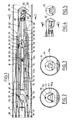
- This device comprises a body 20 produced in several parts, in this case three, produced and arranged so as to fulfill several functions which will be described in more detail below. These three parts are: an external part 22, a front central part 24 and a rear central part 26.
- the outer part 22 is received in a sheath 28 whose inner surface 29 preferably has a frustoconical shape, this sheath being fixed in any suitable known manner to the end of the casing 16, for example by means of a collar 30.
- This outer part 22 is hollow and has at its end directed downstream of the device a head 32 projecting from the sheath and which is pierced with an axial duct 34 and three conduits 35, separated from the conduit 34 and which open into the side wall of the head 32.
- the conduits 35 are arranged at 120 o relative to one another. Depending on the size of the device, a greater number of such conduits can be provided, for example 6.
- the conduit 34 opens into a housing 36 in which is fixed a nozzle 38 for spraying fluid.
- the deflector 44 is mounted on a ball joint 46 and has an unbalance sufficient to occupy a determined position relative to the adjacent drain, the concave wall 45 of this deflector being directed towards the bottom wall of this drain.
- this concave part 45 to 45 b can take various forms, depending on whether one wishes to obtain a wide jet (Fig. 2) or a narrower jet (Fig. 3).
- the part 22 of the body comprises a housing 48 in which is received the central part 24 of the body which delimits, on the one hand, an axial through conduit 50 arranged in the extension of the conduit 34, at least one radial passage 52 making this central duct communicate with an annular duct 54 delimited between the central parts of the body and the external part, and at least one longitudinal duct 56, which is part of the return path of the fluid loaded with solid particles.
- three conduits 56 are provided, arranged in the extension of the three conduits 35.
- the outer part of the body has a tubular shape with a frustoconical intermediate portion 22 a and two cylindrical end portions 22 b , 22 c , the end portion 22 b of smaller diameter being connected to the inner casing 14 by a fitting 60.
- the latter includes two sets of conduits: a first set of three conduits 62 which provide communication between the interior 19 of the casing 14 and an annular conduit 64 delimited between the exterior part of the body and the rear central part 26 of this same body, - A second set of three conduits 66 ensuring communication between the annular space 17 delimited between the two casings, and the axial conduit 73 of the body.
- the rear central part 26 of the body is fixed on the one hand to the internal downstream end of the connector 60 and on the other hand to the external wall of the front central body 24.
- the part 26 forms a venturi and delimits a converging cone 68, a neck 70 then a divergent cone 72 to constitute with an injector 74 fixed in the central body a suction device whose function will be specified below.
- the outer casing is held in the drain 10 by an elastic centering device 76 of known construction.
- a cup 78 is interposed between the outer casing 16 and the connector 60 in order to avoid the deposit of sand or other solid particles at the end of the annular gap 80 delimited between the body and the outer casing.
- the inner casing 14 is supplied with fluid, in this case water, from the surface.
- fluid in this case water
- This fluid, arriving in the connector 60 passes from the axial duct 19 to the annular duct 64 delimited between the central and external parts of the body, to reach the radial passage 58.
- the working fluid is divided into two directed flows, one towards the nozzle 38 and the other towards the injector 74.
- the respective sections of the nozzle and the injector are chosen so as to obtain a determined distribution of the flow rate, which can be for example 3 / 5th of the incident flow in the direction of the injector and 2 / 5th in the direction of the nozzle 38.
- the jet of fluid emitted by the nozzle 38 is deflected by the deflector 44 towards the lower wall of the drain and causes effective agitation of the solid particles of sand or other sediments accumulated in the drain.
- the fluid charged with these particles is sucked at the level of the conduit 35, this suction effect being caused in the venturi 68-72 by the second flow of working liquid, emitted by the injector 74.
- the working fluid and the working liquid particles mix in the part 70, 72 of the body and are directed towards the surface by crossing the connection 60 by the conduits 66 and by traversing the annular conduit 17 delimited between the two casings.
- the concave shape of the deflector makes it possible to give the jet an optimal shape, according to the size and the consistency of the sandy deposits.
- this deposit is often made coherent by deposits of hydrocarbons, which makes the energy concentration effect obtained by the apparatus according to the invention all the more important.
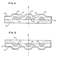
- FIG. 4 and 5 There is shown in Figures 4 and 5 a mounting variant of the deflector, according to which the ball joint of Figure 1 is replaced by a mounting around an axis 82 on which the deflector is mounted oscillating.
- the unbalance of the deflector can be obtained by various means such as the asymmetrical shape of the deflector, the asymmetrical lightening of the latter or the use of materials with different densities.
- the device can be the subject of many other variants, both in the production of the parts that compose it and in the number and arrangement of the various supply and return conduits for the cleaning fluid.
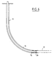
- FIG. 6 represents a main casing 12 which extends from the surface and which comprises a substantially vertical part, then a curved part, to be extended by the substantially horizontal drain 10.
- the external casing 16 provided with its centering device 76 and carrying the sleeve 28 at its end is introduced into this main casing.
- the casings 14 and 16 can be formed either by rigid tubes screwed to each other, or by continuous elements unwound from the surface.
- the installation can of course be completed by connecting the inner casing to a pump supplying water under an appropriate pressure, and by connecting the outer casing to known means for extracting the liquid laden with particles.
- connection box 100 is used for this purpose making it possible to switch from a concentric arrangement of the casings 14, 16 downstream of this box, to a side-by-side arrangement, upstream of said box.
- the connection box 100 is divided into two chambers 102, 104 of which the first 102 can be connected at its upper part to a casing 106 whose section corresponds to the section of the annular gap between the two concentric casings 14 and 16 while it opens at its lower end into a section of tube 108 which can be connected by a connector 110 to the upper part of the outer casing 16.
- Figure 9 is a block diagram, the shapes are actually adapted to assume a good flow.
- the second chamber 104 is connected at its upper part to a casing 112 of the same section as the inner casing 14, while at its lower part it opens into a section of tube 114 which can be connected to the inner casing 14, either by a simple connection if the two inner and outer casings are substantially at the same level, preferably by a sleeve 116 and a fitting 118, as is generally the case, the two concentric casings do not have the same length.
- connection box 100 is lowered into the main casing, the additional casing elements 106 and 112 being added to the upper part of this box, when the device must be advanced down the drain.
- the casing 112 is connected to a pump 114 and the casing 106 to a settling tank 116.
- Such an arrangement is particularly advantageous because it facilitates the addition of additional tubing, the side-by-side arrangement being in this respect much more favorable than the concentric arrangement.
- the device according to the invention also has great flexibility of use and adaptation.
- the orientable or articulated deflector can be replaced by a fixed deflector disposed substantially perpendicular to the axial jet, and which projects the fluid onto a 360 o angle.
- the conduits 35 may in particular have an axial direction.
Abstract
Selon une caractéristique importante de cette invention, l'appareil comprend une duse ou buse (38) de projection de fluide de nettoyage, associées à un déflecteur (44) qui dirige le jet de fluide en direction de la paroi du drain et en particulier vers la paroi inférieure de ce dernier où les sédiments solides s'accumulent. Selon une variante de la présente invention, le jet de fluide émis par la duse (38), chargé des particules retirées du drain est aspiré par effet Venturi et ramené à la surface.According to an important characteristic of this invention, the apparatus comprises a nozzle or nozzle (38) for spraying cleaning fluid, associated with a deflector (44) which directs the jet of fluid towards the wall of the drain and in particular towards the lower wall of the latter where solid sediments accumulate. According to a variant of the present invention, the jet of fluid emitted by the nozzle (38), charged with the particles removed from the drain is sucked in by the Venturi effect and brought back to the surface.
Description
La présente invention concerne les appareils et installations destinés à effectuer le nettoyage de drains horizontaux dans des puits de production pétrolière.The present invention relates to apparatus and installations for cleaning horizontal drains in oil production wells.
On sait que la mise en production de puits dans des gisements sableux, au moyen de drains horizontaux, conduit à l'entraînement de sable par le fluide s'écoulant du gisement et à des dépots importants dans ce sable ou d'autres sédiments, principalement dans la partie horizontale des drains. Il en résulte une diminution sensible de la production du puits.We know that the putting into production of wells in sandy deposits, by means of horizontal drains, leads to the entrainment of sand by the fluid flowing from the deposit and to significant deposits in this sand or other sediments, mainly in the horizontal part of the drains. This results in a significant decrease in the production of the well.
On connait par le brevet US-A-4.744.420 un appareil de nettoyage de tels drains horizontaux, qui comporte à l'extrémité de deux tubages concentriques un corps muni de duses ou buses de projection d'un fluide de nettoyage, ce corps délimitant un trajet d'alimentation en fluide de nettoyage, relié auxdites duses, ainsi qu'un trajet de retour de ce fluide chargé de particules solides de sable ou autres sédiments, ces deux trajets étant reliés respectivement à l'un des deux conduits délimités par les deux tubages concentriques.Patent US-A-4,744,420 discloses a device for cleaning such horizontal drains, which comprises at the end of two concentric casings a body provided with nozzles or nozzles for projecting a cleaning fluid, this body delimiting a cleaning fluid supply path, connected to said nozzles, as well as a return path of this fluid charged with solid particles of sand or other sediments, these two paths being respectively connected to one of the two conduits delimited by the two concentric casings.
Dans cet appareil connu, les duses de projection du fluide de nettoyage sont disposées à l'extrémité du corps et orientées sensiblement parallèlement à l'axe du drain. Une telle disposition tend à chasser en avant de l'appareil le sable et les autres sédiments accumulés dans le drain.In this known device, the spray nozzles for cleaning fluid are arranged at the end of the body and oriented substantially parallel to the axis of the drain. Such an arrangement tends to expel in front of the device the sand and the other sediments accumulated in the drain.
C'est notamment ce problème que l'invention se propose de résoudre, de façon à réaliser un nettoyage plus efficace de tels drains horizontaux ou sensiblement horizontaux.It is this problem in particular that the invention proposes to solve, so as to achieve more effective cleaning of such horizontal or substantially horizontal drains.
A cet effet, l'invention a pour objet un appareil pour le nettoyage d'un drain horizontal ou à faible pente, adapté pour être disposé à l'extrémité aval de deux tubages concentriques délimitant deux conduits également concentriques, cet appareil comprenant un corps qui est muni à son extrémité d'au moins une duse de projection de fluide et qui délimite d'une part un trajet d'alimentation en fluide de nettoyage et d'autre part un trajet de retour pour le fluide chargé de particules solides de sable ou autres sédiments, ces deux trajets étant destinés à être reliés respectivement aux deux conduits délimités par les tubages, caractérisé en ce qu'il comporte des moyens déflecteurs adaptés pour diriger le jet de fluide sortant de la ou chaque duse en direction de la paroi du drain.To this end, the subject of the invention is an apparatus for cleaning a horizontal or gently sloping drain, adapted to be arranged at the downstream end of two concentric casings delimiting two equally concentric conduits, this apparatus comprising a body which is provided at its end with at least one fluid projection nozzle and which delimits on the one hand a cleaning fluid supply path and on the other hand a return path for the fluid loaded with solid particles of sand or other sediments, these two paths being intended to be connected respectively to the two conduits delimited by the casings, characterized in that it comprises deflector means suitable for directing the jet of fluid leaving the or each nozzle towards the wall of the drain .
Suivant d'autres caractéristiques :
- le déflecteur est agencé de façon à orienter le jet de fluide vers le bas,
- le déflecteur est articulé sur un support lui-même fixé sur la partie aval du corps,
- le trajet d'alimentation en fluide comprend, de l'amont vers l'aval, dans le corps, un conduit annulaire, au moins un passage radial et un conduit axial, et le trajet de retour du fluide chargé de particules comprend, de l'aval vers l'amont, au moins un conduit s'étendant à partir de la paroi latérale de la partie avant du corps, au moins un conduit longitudinal, un conduit annulaire entourant un injecteur de fluide moteur et un conduit axial,
- le conduit annulaire et le conduit axial du trajet de retour forment un venturi qui constitue avec l'injecteur un dispositif d'aspiration,
- l'injecteur est alimenté en fluide moteur à partir du passage radial et du conduit axial du trajet d'alimentation, le débit de fluide se répartissant dans le conduit axial en deux flux opposés, dirigés respectivement vers la duse et vers l'injecteur,
- le corps est relié à sa partie arrière ou amont à un raccord comportant deux jeux de conduits qui font communiquer respectivement un conduit axial amont avec un conduit annulaire aval et un conduit annulaire amont avec un conduit axial aval.According to other characteristics:
- the deflector is arranged so as to orient the jet of fluid downwards,
- the deflector is articulated on a support itself fixed on the downstream part of the body,
the fluid supply path comprises, from upstream to downstream, in the body, an annular conduit, at least one radial passage and an axial conduit, and the return path of the fluid loaded with particles comprises, downstream upstream, at least one duct extending from the side wall of the front part of the body, at least one longitudinal duct, an annular duct surrounding a driving fluid injector and an axial duct,
the annular duct and the axial duct of the return path form a venturi which constitutes with the injector a suction device,
the injector is supplied with working fluid from the radial passage and the axial duct of the supply path, the fluid flow being distributed in the axial duct in two opposite flows, directed respectively towards the nozzle and towards the injector,
- The body is connected at its rear or upstream part to a connector comprising two sets of conduits which communicate respectively an upstream axial conduit with a downstream annular conduit and an upstream annular conduit with a downstream axial conduit.
L'invention a également pour objet une installation comportant un tel appareil et caractérisée de plus en ce qu'elle comprend une boîte de raccordement divisée en deux chambres reliées à leur partie amont à deux tubages disposés côte à côte et à leur partie aval aux deux tubages concentriques.The invention also relates to an installation comprising such an apparatus and further characterized in that it comprises a connection box divided into two chambers connected at their upstream part to two casings arranged side by side and at their downstream part to the two concentric casings.
L'invention va être décrite plus en détail ci-dessous en se référant aux dessins annexés, donnés uniquement à titre d'exemple et sur lesquels :
- - la figure 1 est une vue en coupe longitudinale d'un appareil suivant l'invention,
- - la figure 2 est une vue en coupe suivant la ligne 2-2 de la figure 1,
- - la figure 3 est une vue en coupe analogue à celle de la figure 2 d'une variante de réalisation,
- - la figure 4 est une vue partielle en coupe longitudunale d'une autre variante de réalisation,
- - la figure 5 est une vue en coupe suivant la ligne 5-5 de la figure 4,
- - les figures 6, 7 et 8 sont trois vues schématiques illustrant trois phases successives de la mise en oeuvre d'une installation selon l'invention,
- - la figure 9 est une vue de détail en coupe d'une boïte de raccordement utilisée dans une telle installation.
- FIG. 1 is a view in longitudinal section of an apparatus according to the invention,
- FIG. 2 is a sectional view along line 2-2 of FIG. 1,
- FIG. 3 is a sectional view similar to that of FIG. 2 of an alternative embodiment,
- FIG. 4 is a partial view in longitudinal section of another alternative embodiment,
- FIG. 5 is a sectional view along line 5-5 of FIG. 4,
- FIGS. 6, 7 and 8 are three schematic views illustrating three successive phases of the implementation of an installation according to the invention,
- - Figure 9 is a detailed sectional view of a connection box used in such an installation.
On voit sur la figure 1 un tronçon de drain 10 horizontal ou sensiblement horizontal relié à un tubage principal 1 (Fig. 6).FIG. 1 shows a horizontal or substantially
Dans ce drain, sont disposés deux tubages concentriques 14, 16 délimitant entre eux un conduit annulaire 17, tandis que le tubage intérieur délimite un conduit axial 19. L'extrémité aval du tubage intérieur 14 est située en retrait par rapport à l'extrémité aval du tubage extérieur et c'est entre ces deux extrémités qu'est disposé l'appareil selon l'invention.In this drain, are arranged two
Cet appareil comprend un corps 20 réalisé en plusieurs parties en l'occurence trois, réalisées et agencées de façon à remplir plusieurs fonctions qui vont être décrites plus en détail ci-après. Ces trois parties sont : une partie extérieure 22, une partie centrale avant 24 et une partie centrale arrière 26.This device comprises a
La partie extérieure 22 est reçue dans un fourreau 28 dont la surface intérieure 29 a de préférence une forme tronconique, ce fourreau étant fixé de toute façon convenable connue à l'extrémité du tubage 16, par exemple au moyen d'un collier 30.The
Cette partie extérieure 22 est creuse et comporte à son extrémité dirigée vers l'aval de l'appareil une tête 32 en saillie par rapport au fourreau et qui est percée d'un conduit axial 34 et de trois conduits 35, séparés du conduit 34 et qui débouchent dans la paroi latérale de la tête 32. Les conduits 35 sont disposés à 120o l'un uns par rapport aux autres. Selon la dimension de l'appareil, un nombre supérieur de tels conduits peut être prévu, par exemple 6. Le conduit 34 débouche dans un logement 36 dans lequel est fixée une duse 38 de projection de fluide.This
Sur cette mëme tête est fixé par des organes de liaison tels que, par exemple, les trois entretoises 40, un support 42 pour un déflecteur 44 qui se trouve en face de la duse 38. Dans le mode de réalisation représenté à la figure 1, le déflecteur 44 est monté sur une rotule 46 et présente un balourd suffisant pour occuper une position déterminée par rapport au drain adjacent, la paroi concave 45 de ce déflecteur étant dirigée vers la paroi inférieure de ce drain.On this same head is fixed by connecting members such as, for example, the three
Comme représenté aux figures 2 et 3, cett partie concave 45a 45b peut prendre diverses formes, selon que l'on souhaite obtenir un jet large (Fig. 2) ou un jet plus étroit (Fig. 3).As shown in Figures 2 and 3, this
En arrière du conduit 34, la partie 22 du corps comporte un logement 48 dans lequel est reçue la partie centrale 24 du corps qui délimite d'une part un conduit axial traversant 50 disposé dans le prolongement du conduit 34, au moins un passage radial 52 faisant communiquer ce conduit central avec un conduit annulaire 54 délimité entre les parties centrales du corps et la partie extérieure, et au moins un conduit longitudinal 56, qui fait partie du trajet de retour du fluide chargé de particules solides. Dans le mode de réalisation représenté, il est prévu trois conduits 56, disposés dans le prolongement des trois conduits 35.Behind the
En remontant vers l'arrière, la partie extérieure du corps présente une forme tubulaire avec une portion intermédiaire tronconique 22a et deux portions d'extrémité cylindriques 22b, 22c, la partie d'extrémité 22b de plus petit diamètre étant reliée au tubage intérieur 14 par un raccord 60.Going backwards, the outer part of the body has a tubular shape with a frustoconical
Ce dernier comporte deux jeux de conduits :
- un premier jeu de trois conduits 62 qui assurent la communication entre l'intérieur 19 du tubage 14 et un conduit annulaire 64 délimité entre la partie extérieure du corps et la partie centrale arrière 26 de ce même corps,
- un deuxième jeu de trois conduits 66 assurant la communication entre l'espace annulaire 17 délimité entre les deux tubages, et le conduit axial 73 du corps.The latter includes two sets of conduits:
a first set of three
- A second set of three
La partie centrale arrière 26 du corps est fixée d'une part à l'extrémité aval interne du raccord 60 et d'autre part sur la paroi externe du corps central avant 24. La pièce 26 forme un venturi et délimite un cône convergent 68, un col 70 puis un cône divergent 72 pour constituer avec un injecteur 74 fixé dans le corps central un dispositif d'aspiration dont la fonction sera précisée ci-après.The rear
Le tubage extérieur est maintenu dans le drain 10 par un dispositif de centrage élastique 76 de construction connue.The outer casing is held in the
Par ailleurs, une coupelle 78 est interposée entre le tubage extérieur 16 et le raccord 60 afin d'éviter le dépot de sable ou autres particules solides à l'extrémité de l'intervalle annulaire 80 délimité entre le corps et le tubage extérieur.Furthermore, a
Le fonctionnement de cet appareil est le suivant :The operation of this device is as follows:
Le tubage intérieur 14 est alimenté en fluide, en l'occurence de l'eau, à partir de la surface. Ce fluide, parvenant dans le raccord 60 passe du conduit axial 19 vers le conduit annulaire 64 délimité entre les parties centrales et extérieure du corps, pour parvenir jusqu'au passage radial 58.The
Parvenu dans le conduit axial 50, le fluide moteur se divise en deux flux dirigés, l'un vers la duse 38 et l'autre vers l'injecteur 74. Les sections respectives de la duse et de l'injecteur sont choisies de façon à obtenir une répartition déterminée du débit, qui peut être par exemple de 3/5e du débit incident en direction de l'injecteur et 2/5e en direction de la duse 38.Arrived in the
Le jet de fluide émis par la duse 38 est dévié par le déflecteur 44 vers la paroi inférieure du drain et provoque une agitation efficace des particules solides de sable ou autres sédiments accumulés dans le drain. Le fluide chargé de ces particules est aspiré au niveau du conduit 35, cet effet d'aspiration étant provoqué dans le venturi 68-72 par le deuxième flux de liquide moteur, émis par l'injecteur 74. Le fluide moteur et le liquide chargé de particules se mélangent dans la partie 70, 72 du corps et sont dirigés vers la surface en traversant le raccord 60 par les conduits 66 et en parcourant le conduit annulaire 17 délimité entre les deux tubages.The jet of fluid emitted by the
La présence d'une duse unique et d'un déflecteur orientant le jet de fluide vers le drain, ont pour effet de concentrer l'énergie du jet vers le dépot sableux et l'on obtient ainsi une efficacité sensiblement améliorée.The presence of a single nozzle and of a deflector orienting the jet of fluid towards the drain, have the effect of concentrating the energy of the jet towards the sandy deposit and a substantially improved efficiency is thus obtained.
Par ailleurs, la forme concave du déflecteur permet de donner au jet une forme optimale, selon l'importance et la consistance des dépots sableux. A cet égard, on peut noter que ce dépot est souvent rendu cohérent par des dépots d'hydrocarbures, ce qui rend d'autant plus important l'effet de concentration d'énergie obtenu par l'appareil selon l'invention.Furthermore, the concave shape of the deflector makes it possible to give the jet an optimal shape, according to the size and the consistency of the sandy deposits. In this regard, it can be noted that this deposit is often made coherent by deposits of hydrocarbons, which makes the energy concentration effect obtained by the apparatus according to the invention all the more important.
Il est par ailleurs avantageux d'utiliser un conduit annulaire pour le retour du fluide chargé de particules car la section disponible est plus importante.It is also advantageous to use an annular conduit for the return of the fluid charged with particles because the available section is larger.
On a représenté aux figures 4 et 5 une variante de montage du déflecteur, selon laquelle la rotule de la figure 1 est remplacée par un montage autour d'un axe 82 sur lequel le déflecteur est monté oscillant.There is shown in Figures 4 and 5 a mounting variant of the deflector, according to which the ball joint of Figure 1 is replaced by a mounting around an
A cet égard, on peut ajouter que le balourd du déflecteur peut être obtenu par différents moyens tels que forme dissymétrique du déflecteur, allégement dissymétrique de ce dernier ou utilisation de matériaux de masses volumiques différentes.In this regard, it can be added that the unbalance of the deflector can be obtained by various means such as the asymmetrical shape of the deflector, the asymmetrical lightening of the latter or the use of materials with different densities.
D'une façon plus générale, l'appareil peut faire l'objet de nombreuses autres variantes, tant dans la réalisation des pièces qui le composent que dans le nombre et la disposition des différents conduits d'amenée et de retour du fluide de nettoyage.More generally, the device can be the subject of many other variants, both in the production of the parts that compose it and in the number and arrangement of the various supply and return conduits for the cleaning fluid.
On va maintenant décrire à propos des autres figures une installation à laquelle est intégré l'appareil décrit ci-dessus, ainsi qu'un mode opératoire.We will now describe in connection with the other figures an installation in which the apparatus described above is integrated, as well as an operating mode.
La figure 6 représente un tubage principal 12 qui s'étend à partir de la surface et qui comporte une partie sensiblement verticale, puis une partie courbe, pour se prolonger par le drain 10 sensiblement horizontal.FIG. 6 represents a
On introduit tout d'abord dans ce tubage principal le tubage extérieur 16 muni de son dispositif de centrage 76 et portant à son extrémité le fourreau 28.First of all, the
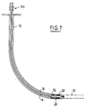
Puis, comme représenté sur la figure 7, on descend à l'intérieur du tubage 16 le tubage intérieur 14 portant à son extrémité l'appareil proprement dit qui prend place dans le siège constitué par le fourreau 28.Then, as shown in FIG. 7, one descends inside the
Comme cela est connu dans la technique, les tubages 14 et 16 peuvent être constitués soit par des tubes rigides vissés les uns aux autres, soit par des éléments continus déroulés depuis la surface.As is known in the art, the
L'installation peut bien entendu être complétée en reliant le tubage intérieur à une pompe fournissant de l'eau sous une pression appropriée, et en reliant le tubage extérieur à des moyens connus d'extraction du liquide chargé de particules.The installation can of course be completed by connecting the inner casing to a pump supplying water under an appropriate pressure, and by connecting the outer casing to known means for extracting the liquid laden with particles.
Cependant, suivant une caractéristique supplémentaire de l'invention, on utilise à cet effet une boîte de raccordement 100 permettant de passer d'une disposition concentrique des tubages 14, 16 en aval de cette boîte, à une disposition côte à côte, en amont de ladite boîte. Ce résultat est obtenu grâce à l'agencement représenté à la figure 9 sur laquelle on peut voir que la boîte de raccordement 100 est divisée en deux chambres 102, 104 dont la première 102 peut être reliée à sa partie supérieure à un tubage 106 dont la section correspond à la section de l'intervalle annulaire entre les deux tubages concentriques 14 et 16 tandis qu'elle débouche à son extrémité inférieure dans un tronçon de tube 108 pouvant être relié par un raccord 110 à la partie supérieure du tubage extérieur 16.However, according to an additional characteristic of the invention, a
La figure 9 est un schéma de principe, les formes étant en réalité adaptées à assumer un bon écoulement.Figure 9 is a block diagram, the shapes are actually adapted to assume a good flow.
La deuxième chambre 104 est reliée à sa partie supérieure à un tubage 112 de même section que le tubage intérieur 14, tandis qu'à sa partie inférieure elle débouche dans un tronçon de tube 114 qui peut être relié au tubage intérieur 14, soit par un raccord simple si les deux tubages intérieur et extérieur sont sensiblement au même niveau, soit de préférence par un manchon 116 et un raccord 118, se comme cela est généralement le cas, les deux tubages concentriques n'ont pas la même longueur.The second chamber 104 is connected at its upper part to a
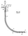
C'est un tel agencement qui est représenté sur la figure 8 où l'on peut voir que la boîte de raccordement 100 est descendue dans le tubage principal, les éléments supplémentaires de tubage 106 et 112 étant rajoutés à la partie supérieure de cette boîte, lorsque l'appareil doit être avancé dans le drain. Le tubage 112 est relié à une pompe 114 et le tubage 106 à un bac de décantation 116.It is such an arrangement which is shown in FIG. 8 where it can be seen that the
Une telle disposition est particulièrement avantageuse car elle facilite l'adjonction de tubages supplémentaires, la disposition côte à côte étant à cet égard beaucoup plus favorable que la disposition concentrique.Such an arrangement is particularly advantageous because it facilitates the addition of additional tubing, the side-by-side arrangement being in this respect much more favorable than the concentric arrangement.
L'appareil suivant l'invention présente par ailleurs de grandes souplesses d'utilisation et d'adaptation. En effet, si l'on souhaite effectuer une opération de nettoyage périphérique de tubage principal ou du drain, on peut remplacer le déflecteur orientable ou articulé par un déflecteur fixe disposé sensiblement perpendiculairement au jet axial, et qui projette le fluide sur un angle de 360o.The device according to the invention also has great flexibility of use and adaptation. In fact, if it is desired to perform a peripheral cleaning operation of the main casing or of the drain, the orientable or articulated deflector can be replaced by a fixed deflector disposed substantially perpendicular to the axial jet, and which projects the fluid onto a 360 o angle.
Les conduits 35 pourront avoir notamment une direction axiale.The
Par ailleurs, la direction de ces conduits 35 ainsi que la distance séparant ces conduits du déflecteur 44 pourront être déterminées pour permettre une évacuation efficace des déblais.Furthermore, the direction of these
Claims (15)
Applications Claiming Priority (2)
| Application Number | Priority Date | Filing Date | Title |
|---|---|---|---|
| FR8911693 | 1989-09-07 | ||
| FR8911693A FR2651451B1 (en) | 1989-09-07 | 1989-09-07 | APPARATUS AND INSTALLATION FOR CLEANING DRAINS, ESPECIALLY IN A WELL FOR OIL PRODUCTION. |
Publications (2)
| Publication Number | Publication Date |
|---|---|
| EP0417009A1 true EP0417009A1 (en) | 1991-03-13 |
| EP0417009B1 EP0417009B1 (en) | 1994-08-17 |
Family
ID=9385209
Family Applications (1)
| Application Number | Title | Priority Date | Filing Date |
|---|---|---|---|
| EP90402457A Expired - Lifetime EP0417009B1 (en) | 1989-09-07 | 1990-09-06 | Device and installation for the cleaning of drains especially in an oil production well |
Country Status (6)
| Country | Link |
|---|---|
| US (1) | US5086842A (en) |
| EP (1) | EP0417009B1 (en) |
| CA (1) | CA2024866C (en) |
| DK (1) | DK0417009T3 (en) |
| FR (1) | FR2651451B1 (en) |
| NO (1) | NO300282B1 (en) |
Cited By (5)
| Publication number | Priority date | Publication date | Assignee | Title |
|---|---|---|---|---|
| WO1992018749A1 (en) * | 1991-04-23 | 1992-10-29 | Den Norske Stats Oljeselskap A.S | Device for collecting particulate matter and debris in horizontal or high deviation oil or gas wells |
| EP0519793A2 (en) * | 1991-06-21 | 1992-12-23 | Institut Français du Pétrole | Device and installation for the cleaning of drain pipes, in particular in oil production wells |
| FR2687084A1 (en) * | 1992-02-06 | 1993-08-13 | Framatome Sa | Device for the remote cleaning of the inside walls of a tube |
| EP0623396A1 (en) * | 1993-05-04 | 1994-11-09 | Friedhelm Ehle | Apparatus for cleaning sewers or pipelines |
| EP0768436A2 (en) * | 1995-10-09 | 1997-04-16 | Norbert Giesler | Device to separate solid substances from liquids, in particular gully, kit and cover for making the same and flushing- and suction pipe for its cleaning |
Families Citing this family (85)
| Publication number | Priority date | Publication date | Assignee | Title |
|---|---|---|---|---|
| US6676627B1 (en) * | 1990-08-06 | 2004-01-13 | Possis Medical, Inc. | Crossflow thrombectomy catheter and system |
| US5435854A (en) * | 1990-08-10 | 1995-07-25 | Pipeline Sewer Services, Inc. | Pipe cleaning modules and systems and methods for their use |
| US5269384A (en) * | 1991-11-08 | 1993-12-14 | Cherrington Corporation | Method and apparatus for cleaning a bore hole |
| US5439174A (en) * | 1994-03-15 | 1995-08-08 | Nelson Irrigation Corporation | Nutating sprinkler |
| US5588595A (en) * | 1994-03-15 | 1996-12-31 | Nelson Irrigation Corporation | Nutating sprinkler |
| CA2122163C (en) * | 1994-04-26 | 1999-04-27 | Jim Edward Best | Method and apparatus for erosive stimulation of open hole formations |
| US5447200A (en) * | 1994-05-18 | 1995-09-05 | Dedora; Garth | Method and apparatus for downhole sand clean-out operations in the petroleum industry |
| US5462118A (en) * | 1994-11-18 | 1995-10-31 | Mobil Oil Corporation | Method for enhanced cleanup of horizontal wells |
| AU3277495A (en) | 1995-07-25 | 1997-02-26 | Downhole Systems Technology Canada | Safeguarded method and apparatus for fluid communication usig coiled tubing, with application to drill stem testing |
| US6128799A (en) * | 1995-10-20 | 2000-10-10 | Nagata; Yukiaki | Conduit interior smoothing device |
| US5671885A (en) * | 1995-12-18 | 1997-09-30 | Nelson Irrigation Corporation | Nutating sprinkler with rotary shaft and seal |
| CA2193923C (en) | 1996-12-24 | 2007-01-23 | Tadeus Sudol | Method of oil/gas stimulation |
| NO306027B1 (en) * | 1997-10-27 | 1999-09-06 | Testtech Services As | Apparatus for removing sand in an underwater well |
| US7879022B2 (en) | 1998-02-06 | 2011-02-01 | Medrad, Inc. | Rapid exchange fluid jet thrombectomy device and method |
| US9586023B2 (en) | 1998-02-06 | 2017-03-07 | Boston Scientific Limited | Direct stream hydrodynamic catheter system |
| US6640897B1 (en) | 1999-09-10 | 2003-11-04 | Bj Services Company | Method and apparatus for through tubing gravel packing, cleaning and lifting |
| US6712150B1 (en) | 1999-09-10 | 2004-03-30 | Bj Services Company | Partial coil-in-coil tubing |
| GB9922378D0 (en) | 1999-09-22 | 1999-11-24 | Specialised Petroleum Serv Ltd | Apparatus incorporating jet pump for well head cleaning |
| US6374838B1 (en) * | 2000-02-01 | 2002-04-23 | Benton F. Baugh | Collapsible pig |
| US6341733B1 (en) | 2000-02-03 | 2002-01-29 | Nelson Irrigation Corporation | Nutating sprinkler |
| US6439477B1 (en) | 2000-02-03 | 2002-08-27 | Nelson Irrigation Corporation | Nutating sprinkler |
| US6427776B1 (en) | 2000-03-27 | 2002-08-06 | Weatherford/Lamb, Inc. | Sand removal and device retrieval tool |
| US6267299B1 (en) | 2000-04-05 | 2001-07-31 | Nelson Irrigation Corporation | Nutating sprinkler with gimbal bearing |
| US6607607B2 (en) | 2000-04-28 | 2003-08-19 | Bj Services Company | Coiled tubing wellbore cleanout |
| US6527050B1 (en) | 2000-07-31 | 2003-03-04 | David Sask | Method and apparatus for formation damage removal |
| GB2371818B (en) * | 2001-02-06 | 2004-09-22 | Ruff Pup Ltd | A casing scraper |
| US6389613B1 (en) | 2001-03-14 | 2002-05-21 | James Comas | Pressure flush control system |
| WO2003062590A1 (en) * | 2002-01-22 | 2003-07-31 | Presssol Ltd. | Two string drilling system using coil tubing |
| US6834722B2 (en) | 2002-05-01 | 2004-12-28 | Bj Services Company | Cyclic check valve for coiled tubing |
| US6755916B1 (en) * | 2002-06-14 | 2004-06-29 | Tdw Delaware, Inc. | Method of dispensing inhibitor in a gas pipeline |
| TW540858U (en) * | 2002-08-28 | 2003-07-01 | Hon Hai Prec Ind Co Ltd | Electrical contact |
| US20060129091A1 (en) | 2004-12-10 | 2006-06-15 | Possis Medical, Inc. | Enhanced cross stream mechanical thrombectomy catheter with backloading manifold |
| US7572244B2 (en) | 2004-08-02 | 2009-08-11 | Medrad, Inc. | Miniature cross stream thrombectomy catheter |
| GB0509962D0 (en) * | 2005-05-17 | 2005-06-22 | Specialised Petroleum Serv Ltd | Device and method for retrieving debris from a well |
| US8012117B2 (en) * | 2007-02-06 | 2011-09-06 | Medrad, Inc. | Miniature flexible thrombectomy catheter |
| US20080188793A1 (en) | 2007-02-06 | 2008-08-07 | Possis Medical, Inc. | Miniature flexible thrombectomy catheter |
| US8162878B2 (en) * | 2005-12-05 | 2012-04-24 | Medrad, Inc. | Exhaust-pressure-operated balloon catheter system |
| US8974418B2 (en) * | 2007-06-12 | 2015-03-10 | Boston Scientific Limited | Forwardly directed fluid jet crossing catheter |
| US20080319386A1 (en) * | 2007-06-20 | 2008-12-25 | Possis Medical, Inc. | Forwardly directable fluid jet crossing catheter |
| US8303538B2 (en) * | 2007-12-17 | 2012-11-06 | Medrad, Inc. | Rheolytic thrombectomy catheter with self-inflating distal balloon |
| WO2009082669A1 (en) | 2007-12-26 | 2009-07-02 | Medrad, Inc. | Rheolytic thrombectomy catheter with self-inflating proximal balloon with drug infusion capabilities |
| DE112009000700T5 (en) | 2008-03-20 | 2011-02-10 | Medrad, Inc. | Hydrodynamic direct current catheter system |
| US9138786B2 (en) | 2008-10-17 | 2015-09-22 | Foro Energy, Inc. | High power laser pipeline tool and methods of use |
| US9244235B2 (en) | 2008-10-17 | 2016-01-26 | Foro Energy, Inc. | Systems and assemblies for transferring high power laser energy through a rotating junction |
| US8627901B1 (en) | 2009-10-01 | 2014-01-14 | Foro Energy, Inc. | Laser bottom hole assembly |
| US9360631B2 (en) | 2008-08-20 | 2016-06-07 | Foro Energy, Inc. | Optics assembly for high power laser tools |
| US9347271B2 (en) * | 2008-10-17 | 2016-05-24 | Foro Energy, Inc. | Optical fiber cable for transmission of high power laser energy over great distances |
| US10301912B2 (en) * | 2008-08-20 | 2019-05-28 | Foro Energy, Inc. | High power laser flow assurance systems, tools and methods |
| US8571368B2 (en) | 2010-07-21 | 2013-10-29 | Foro Energy, Inc. | Optical fiber configurations for transmission of laser energy over great distances |
| US9664012B2 (en) | 2008-08-20 | 2017-05-30 | Foro Energy, Inc. | High power laser decomissioning of multistring and damaged wells |
| US9719302B2 (en) | 2008-08-20 | 2017-08-01 | Foro Energy, Inc. | High power laser perforating and laser fracturing tools and methods of use |
| AU2009340454A1 (en) * | 2008-08-20 | 2010-08-26 | Foro Energy Inc. | Method and system for advancement of a borehole using a high power laser |
| US9027668B2 (en) | 2008-08-20 | 2015-05-12 | Foro Energy, Inc. | Control system for high power laser drilling workover and completion unit |
| US9267330B2 (en) | 2008-08-20 | 2016-02-23 | Foro Energy, Inc. | Long distance high power optical laser fiber break detection and continuity monitoring systems and methods |
| US9242309B2 (en) | 2012-03-01 | 2016-01-26 | Foro Energy Inc. | Total internal reflection laser tools and methods |
| US9669492B2 (en) | 2008-08-20 | 2017-06-06 | Foro Energy, Inc. | High power laser offshore decommissioning tool, system and methods of use |
| US9080425B2 (en) | 2008-10-17 | 2015-07-14 | Foro Energy, Inc. | High power laser photo-conversion assemblies, apparatuses and methods of use |
| US9089928B2 (en) | 2008-08-20 | 2015-07-28 | Foro Energy, Inc. | Laser systems and methods for the removal of structures |
| US7878247B2 (en) * | 2009-01-08 | 2011-02-01 | Baker Hughes Incorporated | Methods for cleaning out horizontal wellbores using coiled tubing |
| US8783361B2 (en) | 2011-02-24 | 2014-07-22 | Foro Energy, Inc. | Laser assisted blowout preventer and methods of use |
| US8783360B2 (en) | 2011-02-24 | 2014-07-22 | Foro Energy, Inc. | Laser assisted riser disconnect and method of use |
| US8684088B2 (en) | 2011-02-24 | 2014-04-01 | Foro Energy, Inc. | Shear laser module and method of retrofitting and use |
| US8720584B2 (en) | 2011-02-24 | 2014-05-13 | Foro Energy, Inc. | Laser assisted system for controlling deep water drilling emergency situations |
| JP2011104520A (en) * | 2009-11-18 | 2011-06-02 | Birukan Co Ltd | Cleaning apparatus |
| US8398579B2 (en) | 2009-12-16 | 2013-03-19 | Medrad, Inc. | Catheter including composite guide and methods for use of the same |
| US7979944B1 (en) * | 2010-03-23 | 2011-07-19 | Bluewater Pipeline Solutions LLC | Tubular cleaning device |
| US8316501B1 (en) | 2010-03-23 | 2012-11-27 | Blue Water Pipeline Solutions, LLC | Tubular cleaning device |
| GB201010192D0 (en) * | 2010-06-17 | 2010-07-21 | Servwell Engineering Ltd | Downhole mixing tool |
| WO2012024285A1 (en) | 2010-08-17 | 2012-02-23 | Foro Energy Inc. | Systems and conveyance structures for high power long distance laster transmission |
| WO2012116155A1 (en) | 2011-02-24 | 2012-08-30 | Foro Energy, Inc. | Electric motor for laser-mechanical drilling |
| WO2012116153A1 (en) | 2011-02-24 | 2012-08-30 | Foro Energy, Inc. | High power laser-mechanical drilling bit and methods of use |
| EP2715887A4 (en) | 2011-06-03 | 2016-11-23 | Foro Energy Inc | Rugged passively cooled high power laser fiber optic connectors and methods of use |
| EP2890859A4 (en) | 2012-09-01 | 2016-11-02 | Foro Energy Inc | Reduced mechanical energy well control systems and methods of use |
| US9211572B2 (en) | 2013-03-05 | 2015-12-15 | Horizon Systems, Inc. | System and method for sanitizing pneumatic conveying piping |
| US9371716B2 (en) * | 2014-05-09 | 2016-06-21 | Chevron U.S.A. Inc. | Self-extendable hydraulic wellbore cleaning tool |
| CN104863532B (en) * | 2015-04-17 | 2017-07-07 | 西安石油大学 | A kind of twin-stage waterpower driven rotary jet Cleaning device for pipeline |
| GB2534243B (en) * | 2015-05-22 | 2017-10-04 | Fourphase As | Selective solid particle separation in oil and/or gas production |
| US10221687B2 (en) | 2015-11-26 | 2019-03-05 | Merger Mines Corporation | Method of mining using a laser |
| NO342858B1 (en) * | 2016-04-01 | 2018-08-20 | Centraflow As | Method and device for directing a fluid flow in an annulus around a pipe string |
| WO2017171556A1 (en) * | 2016-04-01 | 2017-10-05 | Centraflow As | Downhole annular flow diverter |
| US10480275B2 (en) * | 2016-07-06 | 2019-11-19 | Oil & Gas Tech Enterprises C.V. | Coiled tubing spiral venturi tool |
| CN110662612B (en) * | 2017-03-21 | 2022-06-21 | 威廉姆·西伯格 | Cleaning device |
| PL237762B1 (en) * | 2018-03-01 | 2021-05-31 | Eurotech Spolka Z Ograniczona Odpowiedzialnoscia | In-depth tool for hydraulical mining and method for simulation of hydrocarbons extraction |
| US11253883B1 (en) | 2021-06-09 | 2022-02-22 | Russell R. Gohl | Cavity cleaning and coating system |
| US11535321B1 (en) * | 2022-08-24 | 2022-12-27 | Russell R. Gohl | Trailer system |
Citations (5)
| Publication number | Priority date | Publication date | Assignee | Title |
|---|---|---|---|---|
| GB355316A (en) * | 1930-05-09 | 1931-08-10 | Sidney Charles Sladden | Improvements in nozzles |
| US3730592A (en) * | 1971-06-01 | 1973-05-01 | Fmc Corp | Method of subterranean drilling and mining |
| US4630691A (en) * | 1983-05-19 | 1986-12-23 | Hooper David W | Annulus bypass peripheral nozzle jet pump pressure differential drilling tool and method for well drilling |
| US4671359A (en) * | 1986-03-11 | 1987-06-09 | Atlantic Richfield Company | Apparatus and method for solids removal from wellbores |
| US4744420A (en) * | 1987-07-22 | 1988-05-17 | Atlantic Richfield Company | Wellbore cleanout apparatus and method |
Family Cites Families (3)
| Publication number | Priority date | Publication date | Assignee | Title |
|---|---|---|---|---|
| US2735794A (en) * | 1956-02-21 | fletcher | ||
| US4031971A (en) * | 1976-10-08 | 1977-06-28 | Continental Oil Company | Jet nozzle drilling assembly |
| US4909325A (en) * | 1989-02-09 | 1990-03-20 | Baker Hughes Incorporated | Horizontal well turbulizer and method |
-
1989
- 1989-09-07 FR FR8911693A patent/FR2651451B1/en not_active Expired - Lifetime
-
1990
- 1990-09-05 NO NO903864A patent/NO300282B1/en not_active IP Right Cessation
- 1990-09-06 EP EP90402457A patent/EP0417009B1/en not_active Expired - Lifetime
- 1990-09-06 DK DK90402457.7T patent/DK0417009T3/en active
- 1990-09-07 US US07/578,452 patent/US5086842A/en not_active Expired - Lifetime
- 1990-09-07 CA CA002024866A patent/CA2024866C/en not_active Expired - Lifetime
Patent Citations (5)
| Publication number | Priority date | Publication date | Assignee | Title |
|---|---|---|---|---|
| GB355316A (en) * | 1930-05-09 | 1931-08-10 | Sidney Charles Sladden | Improvements in nozzles |
| US3730592A (en) * | 1971-06-01 | 1973-05-01 | Fmc Corp | Method of subterranean drilling and mining |
| US4630691A (en) * | 1983-05-19 | 1986-12-23 | Hooper David W | Annulus bypass peripheral nozzle jet pump pressure differential drilling tool and method for well drilling |
| US4671359A (en) * | 1986-03-11 | 1987-06-09 | Atlantic Richfield Company | Apparatus and method for solids removal from wellbores |
| US4744420A (en) * | 1987-07-22 | 1988-05-17 | Atlantic Richfield Company | Wellbore cleanout apparatus and method |
Cited By (9)
| Publication number | Priority date | Publication date | Assignee | Title |
|---|---|---|---|---|
| WO1992018749A1 (en) * | 1991-04-23 | 1992-10-29 | Den Norske Stats Oljeselskap A.S | Device for collecting particulate matter and debris in horizontal or high deviation oil or gas wells |
| EP0519793A2 (en) * | 1991-06-21 | 1992-12-23 | Institut Français du Pétrole | Device and installation for the cleaning of drain pipes, in particular in oil production wells |
| FR2678021A1 (en) * | 1991-06-21 | 1992-12-24 | Inst Francais Du Petrole | APPARATUS AND INSTALLATION FOR CLEANING DRAINS, IN PARTICULAR IN A PETROLEUM PRODUCTION WELL. |
| EP0519793A3 (en) * | 1991-06-21 | 1993-03-10 | Institut Francais Du Petrole | Device and installation for the cleaning of drain pipes, in particular in oil production wells |
| US5280825A (en) * | 1991-06-21 | 1994-01-25 | Institut Francais Du Petrole | Device and installation for the cleaning of drains, particularly in a petroleum production well |
| FR2687084A1 (en) * | 1992-02-06 | 1993-08-13 | Framatome Sa | Device for the remote cleaning of the inside walls of a tube |
| EP0623396A1 (en) * | 1993-05-04 | 1994-11-09 | Friedhelm Ehle | Apparatus for cleaning sewers or pipelines |
| EP0768436A2 (en) * | 1995-10-09 | 1997-04-16 | Norbert Giesler | Device to separate solid substances from liquids, in particular gully, kit and cover for making the same and flushing- and suction pipe for its cleaning |
| EP0768436A3 (en) * | 1995-10-09 | 1997-07-23 | Norbert Giesler | Device to separate solid substances from liquids, in particular gully, kit and cover for making the same and flushing- and suction pipe for its cleaning |
Also Published As
| Publication number | Publication date |
|---|---|
| US5086842A (en) | 1992-02-11 |
| CA2024866A1 (en) | 1991-03-08 |
| FR2651451B1 (en) | 1991-10-31 |
| FR2651451A1 (en) | 1991-03-08 |
| NO903864L (en) | 1991-03-08 |
| EP0417009B1 (en) | 1994-08-17 |
| NO300282B1 (en) | 1997-05-05 |
| CA2024866C (en) | 2000-09-19 |
| DK0417009T3 (en) | 1994-09-12 |
| NO903864D0 (en) | 1990-09-05 |
Similar Documents
| Publication | Publication Date | Title |
|---|---|---|
| EP0417009B1 (en) | Device and installation for the cleaning of drains especially in an oil production well | |
| EP0519793B1 (en) | Device and installation for the cleaning of drain pipes, in particular in oil production wells | |
| EP2100668B1 (en) | Spray nozzle and liquid spraying device comprising said spray nozzle | |
| FR2812015A1 (en) | Robot for cleaning swimming pool includes suction head and unstable valve causing intermittent action to move robot through pool | |
| EP0086694B1 (en) | Top-blown lance for a metallurgical converter | |
| BE1005201A4 (en) | Crown core. | |
| EP1231326A1 (en) | Pressure injection head | |
| US5720309A (en) | Sewer cleaning nozzle | |
| EP0506534B1 (en) | Liquid sampling head | |
| WO2000021693A1 (en) | Hydrodynamic stirring device and jet pipe | |
| FR2620491A1 (en) | JET PUMP WITH PROPELLER PIPE | |
| EP0216674B1 (en) | Spraying device for spraying powder | |
| EP0037338A2 (en) | Pneumatic transport means for a precision seed drill | |
| EP0327526B1 (en) | Device for cooling a metal during casting | |
| FR3112294A3 (en) | Rotary air conduction spray apparatus with inner and outer air flow channels and rotary air conduction spray unit thereof | |
| FR2595205A1 (en) | Improved spreading boom assembly | |
| FR2529102A1 (en) | SPRAY, ESPECIALLY FOR HEADLIGHTS OF VEHICLES | |
| EP0072746A2 (en) | Hand held spraygun for dispersing a plant treatment liquid | |
| FR2534548A1 (en) | Underwater cleaning apparatus equipped with a suction device for the dirt. | |
| WO2007090957A1 (en) | Window washing device including a spraying means | |
| FR2559050A1 (en) | IMPROVED EQUIPMENT FOR DEEP CLEANING OF TEXTILE SURFACES, MATS, CARPETS OR THE LIKE | |
| FR2552344A1 (en) | Wetting device having several jets for a guniting (shotcreting) gun | |
| FR2679468A1 (en) | Nozzle generating a laminar-flow jet | |
| FR2550098A1 (en) | Device for moistening finely divided solid matter | |
| FR2512048A1 (en) | MULTI-HOLE PRESSURE INJECTOR FOR COKE OVEN |
Legal Events
| Date | Code | Title | Description |
|---|---|---|---|
| PUAI | Public reference made under article 153(3) epc to a published international application that has entered the european phase |
Free format text: ORIGINAL CODE: 0009012 |
|
| 17P | Request for examination filed |
Effective date: 19900921 |
|
| AK | Designated contracting states |
Kind code of ref document: A1 Designated state(s): DK GB IT NL |
|
| 17Q | First examination report despatched |
Effective date: 19921028 |
|
| ITF | It: translation for a ep patent filed |
Owner name: MARIETTI E GISLON S.R.L. |
|
| GRAA | (expected) grant |
Free format text: ORIGINAL CODE: 0009210 |
|
| AK | Designated contracting states |
Kind code of ref document: B1 Designated state(s): DK GB IT NL |
|
| REG | Reference to a national code |
Ref country code: DK Ref legal event code: T3 |
|
| GBT | Gb: translation of ep patent filed (gb section 77(6)(a)/1977) |
Effective date: 19940901 |
|
| PLBE | No opposition filed within time limit |
Free format text: ORIGINAL CODE: 0009261 |
|
| STAA | Information on the status of an ep patent application or granted ep patent |
Free format text: STATUS: NO OPPOSITION FILED WITHIN TIME LIMIT |
|
| 26N | No opposition filed | ||
| PGFP | Annual fee paid to national office [announced via postgrant information from national office to epo] |
Ref country code: DK Payment date: 20000915 Year of fee payment: 11 |
|
| PGFP | Annual fee paid to national office [announced via postgrant information from national office to epo] |
Ref country code: NL Payment date: 20000930 Year of fee payment: 11 |
|
| PG25 | Lapsed in a contracting state [announced via postgrant information from national office to epo] |
Ref country code: DK Free format text: LAPSE BECAUSE OF NON-PAYMENT OF DUE FEES Effective date: 20010906 |
|
| REG | Reference to a national code |
Ref country code: GB Ref legal event code: IF02 |
|
| PG25 | Lapsed in a contracting state [announced via postgrant information from national office to epo] |
Ref country code: NL Free format text: LAPSE BECAUSE OF NON-PAYMENT OF DUE FEES Effective date: 20020401 |
|
| NLV4 | Nl: lapsed or anulled due to non-payment of the annual fee |
Effective date: 20020401 |
|
| REG | Reference to a national code |
Ref country code: DK Ref legal event code: EBP |
|
| NLV4 | Nl: lapsed or anulled due to non-payment of the annual fee |
Effective date: 20020401 |
|
| PGFP | Annual fee paid to national office [announced via postgrant information from national office to epo] |
Ref country code: GB Payment date: 20030818 Year of fee payment: 14 |
|
| PG25 | Lapsed in a contracting state [announced via postgrant information from national office to epo] |
Ref country code: GB Free format text: LAPSE BECAUSE OF NON-PAYMENT OF DUE FEES Effective date: 20040906 |
|
| GBPC | Gb: european patent ceased through non-payment of renewal fee |
Effective date: 20040906 |
|
| PG25 | Lapsed in a contracting state [announced via postgrant information from national office to epo] |
Ref country code: IT Free format text: LAPSE BECAUSE OF NON-PAYMENT OF DUE FEES Effective date: 20050906 |