EP0417675A1 - Vacuum fill system - Google Patents
Vacuum fill system Download PDFInfo
- Publication number
- EP0417675A1 EP0417675A1 EP90117336A EP90117336A EP0417675A1 EP 0417675 A1 EP0417675 A1 EP 0417675A1 EP 90117336 A EP90117336 A EP 90117336A EP 90117336 A EP90117336 A EP 90117336A EP 0417675 A1 EP0417675 A1 EP 0417675A1
- Authority
- EP
- European Patent Office
- Prior art keywords
- container
- vacuum
- flowable materials
- fill system
- flowable
- Prior art date
- Legal status (The legal status is an assumption and is not a legal conclusion. Google has not performed a legal analysis and makes no representation as to the accuracy of the status listed.)
- Granted
Links
Images
Classifications
-
- B—PERFORMING OPERATIONS; TRANSPORTING
- B65—CONVEYING; PACKING; STORING; HANDLING THIN OR FILAMENTARY MATERIAL
- B65B—MACHINES, APPARATUS OR DEVICES FOR, OR METHODS OF, PACKAGING ARTICLES OR MATERIALS; UNPACKING
- B65B1/00—Packaging fluent solid material, e.g. powders, granular or loose fibrous material, loose masses of small articles, in individual containers or receptacles, e.g. bags, sacks, boxes, cartons, cans, or jars
- B65B1/20—Reducing volume of filled material
- B65B1/26—Reducing volume of filled material by pneumatic means, e.g. suction
Definitions
- This invention relates to a vacuum fill system for deaerating flowable materials for storage in a container, and in particular, to a vacuum fill system for deaerating and compacting flowable materials used in flexible bulk containers.
- Containers used in the storage, transportation, and dispensation of flowable materials have been around for as long as civilization itself.
- the use of such containers has always been limited by (1) the weight, density, and other physical properties of the material being stored, and (2) by the process and type of container used to store the material.
- the shipment of smaller sized containers using vacuum sealed packages such as, e.g., vacuum sealed coffee containers, has alleviated many of the above problems of cost and time.
- the present invention substantially eliminates settling and the inherent problems associated therewith by providing a vacuum filling system that deaerates the flowable material during filling.
- the present invention thus allows more product to be transported in the same size container than is possible using prior techniques.
- the present invention allows for the far more efficient total use of all of the container materials and space. No longer is money being spent for container material that is not used. Therefore, the present invention overcomes many of the difficulties inherent in prior filling systems.
- the present invention relates to a vacuum filling system for deaerating flowable materials, and in particular, to a vacuum system for use with flexible bulk containers used to store, transport and dispense flowable materials in semi-bulk quantities.
- the vacuum fill system of the present invention generally comprises a first container for holding the flowable material; means for controlling the flow of the flowable material into the first container; means for creating a vacuum in the first container for deaerating the flowable materials; means for compacting the deaerated material; and means for controlling the flow of the deaerated, compacted flowable material from the first container into a storage container for shipment.
- a first conventional slide or knife gate and valve assembly is located at one end of the first container for controlling the flow of flowable materials into the first container.
- a conventional vacuum pump capable of pulling a vacuum of eighteen (18) inches of mercury, for deaerating the flowable materials is connected to the first container through a series of butterfly valves and vacuum lines.
- a second conventional slide or knife gate and valve assembly is located at the opposite end of the first container for controlling the flow of deaerated flowable material into the storage container.
- Operation of the vacuum fill system is simple and easy.
- the flowable material is placed inside of the first container.
- a vacuum is created through the use of a plurality of valves and a conventional vacuum pump. After sufficient deaeration of the flowable material is achieved, the vacuum is released and the interior of the container is returned to atmosphere pressure substantially instantaneously causing the material to compact.
- the compacted, deaerated flowable material then drops from the first container into a flexible container for shipment.
- compressed air is introduced into the first container to force the compacted, deaerated flowable material from the first container into the flexible container.
- the present invention allows for complete utilization of the flexible container, eliminating wasted space and allowing for the shipment of more material without any increase in the container volume. Therefore, the present invention has numerous advantages over the prior art.
- the vacuum fill system 10 has a hollow, cylindrical container 20, having inner and outer chambers 22 and 24, respectively. Chambers 22 and 24 have first and second ends 26 and 28.
- the inner chamber 22 connects with the outer chamber 24 at the first end 26 of the two chambers.
- the inner chamber 22 has a plurality of openings 30 which allow for the venting of air during use.
- the inner chamber 22 may also be made of a perforated or woven material to allow for better evacuation and compaction.
- a ccnventional knife or slide gate valve 32 and associated air cylinder 34 Attached to the first end 26 of the hollow, cylindrical container 20 and its inner and outer chambers 22 and 24 is a ccnventional knife or slide gate valve 32 and associated air cylinder 34 which controls the opening and closing of the gate 32.
- the slide gate valve 32 and air cylinder 34 are of conventional types well known in the art. When the gate valve 32 is in the open position, flowable material flows through the gate valve 32 and into inner chamber 22 of the hollow, cylindrical container 20.
- a second slide or knife gate valve 36 which is normally of a slightly larger diameter than slide gate valve 32.
- the slide gate valve 36 also has associated with it an air cylinder 38 and switch 40, both well known in the art, which are utilized to open or close the slide gate valve 36 to allow flowable materials to exit from the hollow, cylindrical container 20 after deaeration and compaction.
- a gap 42 between the bottom of the inner chamber 22 and outer chamber 24 of the container 20. The gap 42 allows air to vent and is utilized to help form a vacuum during the deaeration process.
- the outer chamber 24 of the hollow, cylindrical container 20 has a plurality of openings 44 into which vacuum lines 46 run.
- the vacuum lines 46 do not, however, connect to the inner chamber 22.
- One of the vacuum lines 46 is connected to a solenoid actuated butterfly valve 48 which in turn connects to a conventional dust collector (not shown).
- the second vacuum line 46 is connected to a series of solenoid actuated butterfly valves 50 and 52, and from there to a conventional vacuum pump (not shown).
- the vacuum pump must be capable of pulling a minimum of eighteen (18) inches of mercury during operation.
- a conventional pressure switch 54 is Also connected to the second vacuum line 46, which is utilized to control the opening and closing of the valves 50 and 52.
- FIGURES 2 through 5 illustrate the operation of the vacuum fill system of the present invention.
- the vacuum fill system 10 illustrated in FIGURES 2 through 5
- the present invention is capable of being utilized with any type of container no matter how large or small where it is desired to compact, deaerate and densify the flowable materials for packing into a container for shipment and storage.
- FIGURE 2 therein is illustrated the initial start up position of the vacuum fill system 10.
- valves 32, 36, 48 and 50 are closed.
- the flowable material 56 is contained within a conventional holding/storage device 58, such as a hopper.
- the vacuum fill system 10 is connected to a semi-bulk bag 60 through conventional means.
- FIGURE 3 therein it is shown that the hollow, cylindrical container 20 has been filled with flowable material 56.
- valves 32 and 48 have been opened. This results in the opening of slide gate valve 32 and the venting of air through valve 48 to the dust collector during the filling process.
- slide gate valve 32 Once slide gate valve 32 is opened, the flowable material fills the inner chamber 22 up to the level of the openings 30. Openings 30 and gap 42 allow the dust to be vented to the dust collector through valve 48 and vacuum lines 46.
- valve 32 automatically closes preventing the flow of further flowable material 56 into the inner chamber 22 of the hollow, cylindrical container 20.
- valves 48 and 52 are also closed automatically and valve 50 is opened. This creates a vacuum in the space between the inner and outer chambers 22 and 24.
- FIGURE 4 therein is illustrated that flowable material 56 has been deaerated and compacted and that the volume of material 56 is now significantly less than when first introduced into the hollow, cylindrical container 20.
- the volume of flowable material 56 actually increases slightly as the internal air passes through it and the vacuum is created. Thus, there is actually a volume gain until the chamber is returned to atmospheric pressure.
- valve 52 is opened immediately. Valve 52 must be opened suddenly and fully in order to get a high impact on the material 56 from the entering air. The impact of the entering air compresses and compacts the deaerated, flowable material 56, both axially and radially, due to the internal low pressure previously created by the vacuum.
- valve 36 is opened and the compacted, deaerated flowable material 56 flows as a compact "slug" of material into the desired container or, as illustrated, bulk bag 60. Since the compacted and deaerated material is highly densified and only drops a short distance before entering the container 60, there is very little chance of reaeration.
- slide gate valve 36 closes and the vacuum fill system 10 is ready to begin a new cycle.
- a second embodiment of the vacuum fill system 100 has a hollow, tapered chamber 120 having a first end 122 and a second end 124. Attached to the first end 122 of the hollow, tapered chamber 120 is a conventional knife or slide gate valve 126 and an associated air cylinder 128 which controls the opening and closing of the slide gate valve 126.
- the slide gate valve 126 and the air cylinder 128 are of conventional types well known in the art.
- a second knife or slide gate valve 132 At the second end 124 of the hollow, tapered chamber 120, there is a second knife or slide gate valve 132.
- An associated air cylinder 134 and a switch 136 are utilized to open or close the slide gate valve 132 to allow flowable materials to exit the hollow, tapered chamber 120 through a discharge chute 138 after deaeration and compaction.
- the slide gate valve 132, the air cylinder 134 and the switch 136 are of conventional types well known in the art.
- Line 140 runs into an opening 142 in the hollow, tapered chamber 120, and is connected to a solenoid actuated butterfly valve 144 which is in turn connected to a compressed air source (not shown).
- a vacuum line 141 runs into an opening 143 in the hollow, tapered chamber 12u, and is connected to a series of solenoid actuated butterfly valves 146, 148, and 150, and from there to a conventional dust collector 152.
- the dust collector 152 has a knife or slide gate valve 151 and an associated air cylinder 153 to allow discharge of dust and particles from the dust collector.
- Mounted on top of the dust collector is a fan 155.
- Connected to the vacuum line 141 on both sides of the butterfly valve 150 is a vacuum pump or high vacuum venturi 154.
- the vacuum fill system 100 is preferably used in connection with the filling of a semi-bulk container for handling flowable materials, it must be understood that the vacuum fill system 100 is capable of being utilized with any type of container, no matter how large or small, where it is desired to compact, deaerate, and densify the flowable materials for packing into a container for shipment and storage.
- a semi-bulk bag 156 is connected to the vacuum fill system 100 through ccnventional means such as hooks 157 mounted in a frame 159.
- Support loops 161 on the bag 156 are placed over the hooks 157 to suspend the bag below the discharge chute 138.
- a collar 163 on the bag 156 is placed around the discharge chute 138 to prevent spillage while filling the bag 156.
- the slide gate valves 126 and 132 and the solenoid actuated butterfly valves 144, 146, and 150 are closed to allow evacuation of air from the chamber 120.
- the slide gate valve 126 is then opened to fill the hollow, tapered chamber 120 with flowable material.
- the slide gate valve 126 is then closed, the valve 148 remains open and the valve 150 is opened to initiate evacuation of air from the filled tapered chamber 120.
- the valves 146 and 150 are closed and the valve 148 remains open drawing air from the chamber 120 through action of the vacuum pump or high vacuum venturi 154.
- valve 148 is closed and the valve 146 is opened to suddenly vent vacuum line 141 and the tapered chamber 120 to the atmosphere, thereby compacting the deaerated flowable materials within the tapered chamber 120.
- the slide gate valve 132 and the valve 144 are then opened to allow compressed air to be injected into the tapered chamber 120, thereby forcing the flowable materials as a compact "slug" of material from the tapered chamber 120 and into the desired container or, as illustrated, bulk bag 156.
- the slide gate valve 132 closes and the vacuum fill system 100 is ready to begin a new cycle.
- first and second embodiments of the vacuum fill system 10 and 100 may be performed either manually or automatically through the use of conventional electronic circuitry.
Abstract
Description
- This application is a continuation-in-part of co-pending U.S. Application Serial No. 407,901, filed September 15, 1989.
- This invention relates to a vacuum fill system for deaerating flowable materials for storage in a container, and in particular, to a vacuum fill system for deaerating and compacting flowable materials used in flexible bulk containers.
- Containers used in the storage, transportation, and dispensation of flowable materials have been around for as long as civilization itself. The use of such containers, however, has always been limited by (1) the weight, density, and other physical properties of the material being stored, and (2) by the process and type of container used to store the material.
- Traditional filling processes and containers have long been encumbered by a simple phenomenon that has exasperated consumers for decades - settling. Settling, as any purchaser of a bag of potato chips knows, means the bag is never completely filled when opened. This occurs due to the settling of the product inside during its filling and shipment. This simple settling phenomenon causes tremendous economic waste each year because of the misuse of storage space and container materials. This has been particularly true in the storage, transportation, and dispensation of flowable materials in semi-bulk quantities such as grains, chemicals and other bulky substances stored in flexible, bulk containers, such as those disclosed in U.S. Patent Nos. 4,143,796 and 4,194,652.
- It has long been known that the settling process is caused by the natural aeration of flowable materials as the materials are placed inside a container. As the container is shipped to its final destination, the air escapes from the aerated material mixture causing the product to compact and reduce in volume. Thus, when the container is opened, the flowable material has settled to the bottom of the container, i.e. the bag of potato chips is only half full.
- Any process or system, such as the present invention, for storing materials in a container for shipment that allows all of the container to be filled with product and eliminates the excess air results in an enormous cost savings. Indeed, the shipment of smaller sized containers using vacuum sealed packages such as, e.g., vacuum sealed coffee containers, has alleviated many of the above problems of cost and time.
- Although vacuum sealed packaging has proved to be an efficient, cost-saving and consumer pleasing method of shipping small quantities of goods, before now, it has been impossible to apply such techniques into other areas of storage, transportation and dispensation of flowable materials. This has been particularly true in the market for semi-bulk flowable materials.
- The present invention, however, substantially eliminates settling and the inherent problems associated therewith by providing a vacuum filling system that deaerates the flowable material during filling. The present invention thus allows more product to be transported in the same size container than is possible using prior techniques.
- Additionally, by utilizing all of the container space, the present invention allows for the far more efficient total use of all of the container materials and space. No longer is money being spent for container material that is not used. Therefore, the present invention overcomes many of the difficulties inherent in prior filling systems.
- The present invention relates to a vacuum filling system for deaerating flowable materials, and in particular, to a vacuum system for use with flexible bulk containers used to store, transport and dispense flowable materials in semi-bulk quantities.
- The vacuum fill system of the present invention generally comprises a first container for holding the flowable material; means for controlling the flow of the flowable material into the first container; means for creating a vacuum in the first container for deaerating the flowable materials; means for compacting the deaerated material; and means for controlling the flow of the deaerated, compacted flowable material from the first container into a storage container for shipment.
- In the preferred embodiment of the invention, a first conventional slide or knife gate and valve assembly is located at one end of the first container for controlling the flow of flowable materials into the first container. A conventional vacuum pump, capable of pulling a vacuum of eighteen (18) inches of mercury, for deaerating the flowable materials is connected to the first container through a series of butterfly valves and vacuum lines. A second conventional slide or knife gate and valve assembly is located at the opposite end of the first container for controlling the flow of deaerated flowable material into the storage container.
- Operation of the vacuum fill system is simple and easy. The flowable material is placed inside of the first container. A vacuum is created through the use of a plurality of valves and a conventional vacuum pump. After sufficient deaeration of the flowable material is achieved, the vacuum is released and the interior of the container is returned to atmosphere pressure substantially instantaneously causing the material to compact. The compacted, deaerated flowable material then drops from the first container into a flexible container for shipment. In a second embodiment of the invention, compressed air is introduced into the first container to force the compacted, deaerated flowable material from the first container into the flexible container.
- By deaerating and compacting the flowable material before filling the flexible container, through the use of the vacuum fill system, the flowable material is presettled and will not settle during shipment. Thus, the present invention allows for complete utilization of the flexible container, eliminating wasted space and allowing for the shipment of more material without any increase in the container volume. Therefore, the present invention has numerous advantages over the prior art.
- A more complete understanding of the invention may be had by reference to the following Detailed Description when taken in conjunction with the accompanying Drawings, in which:
- FIGURE 1 is a partial sectional view of the vacuum fill system;
- FIGURE 2 is a partial sectional view of the vacuum fill system illustrating its use with semi-bulk bags used for containing flowable materials;
- FIGURE 3 is a partial sectional view of the vacuum fill system illustrating the filling of the first container with flowable material before deaerating;
- FIGURE 4 is a partial sectional view of the vacuum fill system illustrating the deaerated flowable material;
- FIGURE 5 is a partial sectional view of the vacuum fill system illustrating the deaerated flowable material inside the storage container; and
- Figure 6 is a partial sectional view of a second embodiment of the invention.
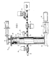
- Referring to FIGURE 1, the
vacuum fill system 10 has a hollow,cylindrical container 20, having inner andouter chambers second ends inner chamber 22 connects with theouter chamber 24 at thefirst end 26 of the two chambers. In the preferred embodiment, theinner chamber 22 has a plurality ofopenings 30 which allow for the venting of air during use. Theinner chamber 22 may also be made of a perforated or woven material to allow for better evacuation and compaction. - Attached to the
first end 26 of the hollow,cylindrical container 20 and its inner andouter chambers slide gate valve 32 and associatedair cylinder 34 which controls the opening and closing of thegate 32. Theslide gate valve 32 andair cylinder 34 are of conventional types well known in the art. When thegate valve 32 is in the open position, flowable material flows through thegate valve 32 and intoinner chamber 22 of the hollow,cylindrical container 20. - At the
second end 28 of the hollow,cylindrical container 20, there is a second slide orknife gate valve 36, which is normally of a slightly larger diameter thanslide gate valve 32. Theslide gate valve 36 also has associated with it anair cylinder 38 andswitch 40, both well known in the art, which are utilized to open or close theslide gate valve 36 to allow flowable materials to exit from the hollow,cylindrical container 20 after deaeration and compaction. Also at thesecond end 28 of thecontainer 20, is agap 42 between the bottom of theinner chamber 22 andouter chamber 24 of thecontainer 20. Thegap 42 allows air to vent and is utilized to help form a vacuum during the deaeration process. - The
outer chamber 24 of the hollow,cylindrical container 20 has a plurality ofopenings 44 into whichvacuum lines 46 run. Thevacuum lines 46 do not, however, connect to theinner chamber 22. In the preferred embodiment of the invention, there are at least twoopenings 44 and twovacuum lines 46 running in opposite directions. One of thevacuum lines 46 is connected to a solenoid actuatedbutterfly valve 48 which in turn connects to a conventional dust collector (not shown). Thesecond vacuum line 46 is connected to a series of solenoid actuatedbutterfly valves - Although any conventional vacuum pump may be utilized with the present invention, the vacuum pump must be capable of pulling a minimum of eighteen (18) inches of mercury during operation. Also connected to the
second vacuum line 46 is aconventional pressure switch 54, which is utilized to control the opening and closing of thevalves - FIGURES 2 through 5 illustrate the operation of the vacuum fill system of the present invention. Although the
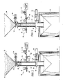
vacuum fill system 10, illustrated in FIGURES 2 through 5, is used in connection with the filling of a semi-bulk container for handling flowable materials, it must be understood that the present invention is capable of being utilized with any type of container no matter how large or small where it is desired to compact, deaerate and densify the flowable materials for packing into a container for shipment and storage. - Turning now to FIGURE 2, therein is illustrated the initial start up position of the
vacuum fill system 10. - In FIGURE 2,
valves flowable material 56 is contained within a conventional holding/storage device 58, such as a hopper. Thevacuum fill system 10 is connected to asemi-bulk bag 60 through conventional means. - Turning to FIGURE 3, therein it is shown that the hollow,
cylindrical container 20 has been filled withflowable material 56. In order to fill thehollow container 20,valves slide gate valve 32 and the venting of air throughvalve 48 to the dust collector during the filling process. Onceslide gate valve 32 is opened, the flowable material fills theinner chamber 22 up to the level of theopenings 30.Openings 30 andgap 42 allow the dust to be vented to the dust collector throughvalve 48 and vacuum lines 46. - The flow of flowable materials into the
inner chamber 22 is controlled either by weight or height level. When the predetermined level or weight is reached,valve 32 automatically closes preventing the flow of furtherflowable material 56 into theinner chamber 22 of the hollow,cylindrical container 20. - At this time,
valves valve 50 is opened. This creates a vacuum in the space between the inner andouter chambers - Turning to FIGURE 4, therein is illustrated that
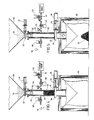
flowable material 56 has been deaerated and compacted and that the volume ofmaterial 56 is now significantly less than when first introduced into the hollow,cylindrical container 20. - When the air is initially evacuated from the
inner chamber 22, the volume offlowable material 56 actually increases slightly as the internal air passes through it and the vacuum is created. Thus, there is actually a volume gain until the chamber is returned to atmospheric pressure. - Once the vacuum reaches the necessary level to achieve the desired deaeration of the
flowable material 56,valve 52 is opened immediately.Valve 52 must be opened suddenly and fully in order to get a high impact on the material 56 from the entering air. The impact of the entering air compresses and compacts the deaerated,flowable material 56, both axially and radially, due to the internal low pressure previously created by the vacuum. - Subsequently,
valve 36 is opened and the compacted, deaeratedflowable material 56 flows as a compact "slug" of material into the desired container or, as illustrated,bulk bag 60. Since the compacted and deaerated material is highly densified and only drops a short distance before entering thecontainer 60, there is very little chance of reaeration. - Finally, after the filling of the
container 60 with theflowable materials 56,slide gate valve 36 closes and thevacuum fill system 10 is ready to begin a new cycle. - Referring now to FIGURE 6, a second embodiment of the
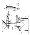
vacuum fill system 100 has a hollow, tapered chamber 120 having afirst end 122 and asecond end 124. Attached to thefirst end 122 of the hollow, tapered chamber 120 is a conventional knife or slidegate valve 126 and an associatedair cylinder 128 which controls the opening and closing of theslide gate valve 126. Theslide gate valve 126 and theair cylinder 128 are of conventional types well known in the art. When theslide gate valve 126 is in the open position, flowable materials flow from aninput source 130 through theslide gate valve 126 into the hollow, tapered chamber 120. - At the
second end 124 of the hollow, tapered chamber 120, there is a second knife or slidegate valve 132. An associatedair cylinder 134 and aswitch 136 are utilized to open or close theslide gate valve 132 to allow flowable materials to exit the hollow, tapered chamber 120 through adischarge chute 138 after deaeration and compaction. Theslide gate valve 132, theair cylinder 134 and theswitch 136 are of conventional types well known in the art. -
Line 140 runs into anopening 142 in the hollow, tapered chamber 120, and is connected to a solenoid actuatedbutterfly valve 144 which is in turn connected to a compressed air source (not shown). - A
vacuum line 141 runs into anopening 143 in the hollow, tapered chamber 12u, and is connected to a series of solenoid actuatedbutterfly valves conventional dust collector 152. Thedust collector 152 has a knife or slidegate valve 151 and an associatedair cylinder 153 to allow discharge of dust and particles from the dust collector. Mounted on top of the dust collector is afan 155. Connected to thevacuum line 141 on both sides of thebutterfly valve 150 is a vacuum pump orhigh vacuum venturi 154. - As with the first embodiment of the invention, although the
vacuum fill system 100 is preferably used in connection with the filling of a semi-bulk container for handling flowable materials, it must be understood that thevacuum fill system 100 is capable of being utilized with any type of container, no matter how large or small, where it is desired to compact, deaerate, and densify the flowable materials for packing into a container for shipment and storage. - Still referring to FIGURE 6, during operation of the
vacuum fill system 100, asemi-bulk bag 156 is connected to thevacuum fill system 100 through ccnventional means such ashooks 157 mounted in aframe 159.Support loops 161 on thebag 156 are placed over thehooks 157 to suspend the bag below thedischarge chute 138. Acollar 163 on thebag 156 is placed around thedischarge chute 138 to prevent spillage while filling thebag 156. - Before flowable materials are introduced into the hollow, tapered chamber 120, the
slide gate valves butterfly valves slide gate valve 126 is then opened to fill the hollow, tapered chamber 120 with flowable material. Theslide gate valve 126 is then closed, thevalve 148 remains open and thevalve 150 is opened to initiate evacuation of air from the filled tapered chamber 120. To further evacuate the filled tapered chamber 120, thevalves valve 148 remains open drawing air from the chamber 120 through action of the vacuum pump orhigh vacuum venturi 154. - Once the vacuum reaches the necessary level to achieve the desired deaeration of the flowable material, the
valve 148 is closed and thevalve 146 is opened to suddenly ventvacuum line 141 and the tapered chamber 120 to the atmosphere, thereby compacting the deaerated flowable materials within the tapered chamber 120. - The
slide gate valve 132 and thevalve 144 are then opened to allow compressed air to be injected into the tapered chamber 120, thereby forcing the flowable materials as a compact "slug" of material from the tapered chamber 120 and into the desired container or, as illustrated,bulk bag 156. - After the "slug" of material is ejected from the tapered chamber 120 under the force of the compressed air, the
slide gate valve 132 closes and thevacuum fill system 100 is ready to begin a new cycle. - Although not shown, it should be understood that the operation of the first and second embodiments of the
vacuum fill system - Although preferred embodiments of the present invention have been illustrated in the accompanying Drawings and described in the foregoing Detailed Description, it will be appreciated by those skilled in the art that various modifications and rearrangements of the component parts and elements of the present invention are possible within the scope of the present invention.
Claims (6)
a first container for holding the flowable materials;
means for controlling the flow of the flowable materials into the first container;
means for creating a vacuum in the first container for deaerating the flowable materials;
means for compacting the deaerated flowable materials; and
means for controlling the flow of the deaerated, compacted flowable material from the first container into a storage container.
a first hollow, cylindrical container having inner and outer chambers, first and second ends, and a plurality of openings;
a first gate valve and air cylinder attached to the first end of the cylindrical container for controlling the flow of the flowable materials into the first cylindrical container;
a plurality of vacuum lines connected to the cylindrical container at the circular openings;
a plurality of valves connected to the vacuum lines;
a vacuum pump connected to the vacuum lines for creating a vacuum in the cylindrical container for deaerating the flowable materials;
means for compacting the deaerated flowable materials;
a second gate valve and air cylinder attached to the second end of the cylindrical container for controlling the flow of the deaerated, compacted flowable material into the storage container; and
means for controlling the operation of the gate valves, valves and vacuum pump.
Priority Applications (1)
| Application Number | Priority Date | Filing Date | Title |
|---|---|---|---|
| AT90117336T ATE98175T1 (en) | 1989-09-15 | 1990-09-08 | VACUUM FILLING SYSTEM. |
Applications Claiming Priority (4)
| Application Number | Priority Date | Filing Date | Title |
|---|---|---|---|
| US40790189A | 1989-09-15 | 1989-09-15 | |
| US407901 | 1989-09-15 | ||
| US55867890A | 1990-07-27 | 1990-07-27 | |
| US558678 | 2000-04-26 |
Publications (2)
| Publication Number | Publication Date |
|---|---|
| EP0417675A1 true EP0417675A1 (en) | 1991-03-20 |
| EP0417675B1 EP0417675B1 (en) | 1993-12-08 |
Family
ID=27020062
Family Applications (1)
| Application Number | Title | Priority Date | Filing Date |
|---|---|---|---|
| EP90117336A Expired - Lifetime EP0417675B1 (en) | 1989-09-15 | 1990-09-08 | Vacuum fill system |
Country Status (5)
| Country | Link |
|---|---|
| US (1) | US5109893A (en) |
| EP (1) | EP0417675B1 (en) |
| JP (1) | JP2881703B2 (en) |
| CA (1) | CA2024304C (en) |
| DE (1) | DE69005065T2 (en) |
Cited By (3)
| Publication number | Priority date | Publication date | Assignee | Title |
|---|---|---|---|---|
| WO1993007056A1 (en) * | 1991-10-04 | 1993-04-15 | Euroc Brick & Tile Ab | Apparatus for filling a sack with a flowable material |
| EP1705117A1 (en) * | 2005-03-25 | 2006-09-27 | Arodo BVBA | Device for packaging a flowable solid material |
| CN109533411A (en) * | 2018-12-24 | 2019-03-29 | 哈尔滨联科包装机械有限公司 | Flour material enriches device and substantial method in packaging bag |
Families Citing this family (47)
| Publication number | Priority date | Publication date | Assignee | Title |
|---|---|---|---|---|
| US5244019A (en) * | 1989-09-15 | 1993-09-14 | Better Agricultural Goals Corp. | Vacuum fill system |
| US5447183A (en) * | 1989-09-15 | 1995-09-05 | B.A.G. Corp. | Vacuum fill system |
| US5538053A (en) * | 1989-09-15 | 1996-07-23 | Better Agricultural Goals Corporation | Vacuum densifier with auger |
| US5531252A (en) * | 1989-09-15 | 1996-07-02 | B.A.G. Corporation | Vacuum fill system |
| US5234037A (en) * | 1989-09-15 | 1993-08-10 | B.A.G. Corporation | Vacuum fill system |
| US5509451A (en) * | 1989-09-15 | 1996-04-23 | B.A.G. Corporation | Vacuum fill system |
| US5271439A (en) * | 1992-02-20 | 1993-12-21 | Semi-Bulk Systems, Inc. | System for unloading powdered or granular materials |
| US5520889A (en) * | 1993-11-02 | 1996-05-28 | Owens-Corning Fiberglas Technology, Inc. | Method for controlling the discharge of granules from a nozzle onto a coated sheet |
| US5599581A (en) * | 1993-11-02 | 1997-02-04 | Owens Corning Fiberglas Technology, Inc. | Method for pneumatically controlling discharge of particulate material |
| CA2175382C (en) * | 1993-11-02 | 2005-01-04 | Charles A. Burton | Pneumatic granule blender for asphalt shingles |
| JPH07172575A (en) * | 1993-12-17 | 1995-07-11 | Nordson Kk | Feeding and carrying method for powder/grain |
| AU693161B2 (en) * | 1994-02-03 | 1998-06-25 | Seec, Inc. | Collapsible container for hauling bulk materials |
| US5553639A (en) * | 1994-02-03 | 1996-09-10 | Seec, Inc. | Container and method for transporting finely divided or dried coal |
| US5624522A (en) * | 1995-06-07 | 1997-04-29 | Owens-Corning Fiberglas Technology Inc. | Method for applying granules to strip asphaltic roofing material to form variegated shingles |
| US5839668A (en) * | 1996-01-29 | 1998-11-24 | Accudyne Corporation | Micro-spacer metering apparatus employing multi-cavity disc and pneumatic ejection head for flat panel display assembly |
| US5747105A (en) | 1996-04-30 | 1998-05-05 | Owens Corning Fiberglas Technology Inc. | Traversing nozzle for applying granules to an asphalt coated sheet |
| US5858095A (en) | 1996-04-30 | 1999-01-12 | Owens Corning Fiberglas Technology, Inc. | Shuttle cutoff for applying granules to an asphalt coated sheet |
| US5904270A (en) * | 1997-07-18 | 1999-05-18 | Schwartz; Louis S. | Material loader and spreader attachment |
| CA2327599C (en) * | 2000-12-05 | 2008-07-08 | Odiel Sanders | Dispensing measured quantities of materials for mixing into a larger batch |
| US20040112456A1 (en) * | 2002-12-16 | 2004-06-17 | Bates James William | Densification of aerated powders using positive pressure |
| DE102004037107A1 (en) * | 2004-05-14 | 2005-12-08 | Haver & Boecker Ohg | Method and device for filling open containers with a powdered product |
| ES2332292T3 (en) * | 2005-11-21 | 2010-02-01 | Mannkind Corporation | APPARATUS AND PROCEDURES FOR DISPENSATION AND DUST DETECTION. |
| WO2007100141A1 (en) | 2006-02-28 | 2007-09-07 | Canon Kabushiki Kaisha | Powder-filling device, powder-filling method, and process cartridge |
| ITBO20070236A1 (en) * | 2007-04-02 | 2008-10-03 | Marchesini Group Spa | METHOD FOR THE DETERMINATION OF POWDERED AND / OR GRANULAR PRODUCTS WITHIN CONTAINER ELEMENTS AND DEVICE FOR IMPLEMENTATION |
| DE102007027110A1 (en) * | 2007-06-13 | 2008-12-18 | Wacker Chemie Ag | Method and apparatus for packaging polycrystalline silicon breakage |
| ITFI20080121A1 (en) * | 2008-06-30 | 2010-01-01 | Saeco Ipr Ltd | "SEPARATION DEVICE BETWEEN DIFFERENT ENVIRONMENTS AND DOSAGE OF A FOOD PRODUCT AND MACHINE INCORPORATING THE DEVICE" |
| PT2684801E (en) | 2008-08-05 | 2015-10-14 | Mannkind Corp | Powder dispensing and sensing apparatus and method of dispensing and sensing powder |
| US8871263B2 (en) | 2009-09-24 | 2014-10-28 | Mcneil-Ppc, Inc. | Manufacture of tablet in a die utilizing radiofrequency energy and meltable binder |
| US8357116B2 (en) | 2010-08-10 | 2013-01-22 | Medela Holding Ag | Bag attachment device for breastpump |
| DE102011101045A1 (en) * | 2011-05-09 | 2012-11-15 | Haver & Boecker Ohg | Packing machine and method for filling open bags |
| US9963253B2 (en) | 2011-07-11 | 2018-05-08 | Altria Client Services Llc | Air accelerator dosing tube |
| US9445971B2 (en) | 2012-05-01 | 2016-09-20 | Johnson & Johnson Consumer Inc. | Method of manufacturing solid dosage form |
| US9511028B2 (en) | 2012-05-01 | 2016-12-06 | Johnson & Johnson Consumer Inc. | Orally disintegrating tablet |
| US9233491B2 (en) | 2012-05-01 | 2016-01-12 | Johnson & Johnson Consumer Inc. | Machine for production of solid dosage forms |
| JP6033740B2 (en) * | 2012-07-04 | 2016-11-30 | 西川ゴム工業株式会社 | Powder input device |
| ES2750323T3 (en) | 2014-01-10 | 2020-03-25 | Johnson & Johnson Consumer Inc | Method for manufacturing a tablet using radio frequency and loss coated particles |
| CA2904286C (en) | 2014-11-04 | 2021-10-19 | Cnh Industrial Canada, Ltd. | Ringed meter rollers and slide cutoff system |
| CA2903633C (en) | 2014-11-04 | 2020-11-24 | Cnh Industrial Canada, Ltd. | Ringed meter rollers and slide cutoff system |
| US9880535B2 (en) | 2014-12-02 | 2018-01-30 | Cnh Industrial Canada, Ltd. | System and method for air cart and rotary air lock |
| US10493026B2 (en) | 2017-03-20 | 2019-12-03 | Johnson & Johnson Consumer Inc. | Process for making tablet using radiofrequency and lossy coated particles |
| EP3672879A4 (en) | 2017-08-22 | 2021-08-25 | TMT Vacuum Fillers, LLC | Vacuum apparatus for filling bulk containers |
| US11089894B2 (en) * | 2019-01-18 | 2021-08-17 | Chicago Show, Inc. | Dry food dispensing apparatus |
| US11753255B2 (en) | 2019-01-18 | 2023-09-12 | Chicago Show, Inc. | Motorized dry food dispensing apparatus |
| DE102019110036A1 (en) * | 2019-04-16 | 2020-10-22 | Apeva Se | Device and method for generating a powder conveyed in a fluid stream |
| CN111232265A (en) * | 2020-03-03 | 2020-06-05 | 武汉轻工大学 | Automatic powder material filling device |
| CN111661373A (en) * | 2020-07-27 | 2020-09-15 | 河津市炬华铝业有限公司 | Powder packing is with packagine machine |
| EP4074610A1 (en) * | 2021-04-14 | 2022-10-19 | GREIF-VELOX Maschinenfabrik GmbH | Method for filling an at least partially gas-permeable container |
Citations (3)
| Publication number | Priority date | Publication date | Assignee | Title |
|---|---|---|---|---|
| CH495873A (en) * | 1969-06-25 | 1970-09-15 | Hoefliger & Karg | Method and device for packing goods in portions with the greatest possible exclusion of oxygen |
| US3586066A (en) * | 1969-05-09 | 1971-06-22 | Vogt Clarence W | Method of filling flexible containers |
| DE2810244A1 (en) * | 1978-03-09 | 1979-09-13 | Franz Hoffmann & Soehne Kg Che | Sack filling system for powdery material - has compression chamber in which trapped air is driven out through permeable sections |
Family Cites Families (18)
| Publication number | Priority date | Publication date | Assignee | Title |
|---|---|---|---|---|
| US2138356A (en) * | 1935-10-01 | 1938-11-29 | Ryan Coffee Corp | Weighing and filling apparatus and method |
| US2142990A (en) * | 1936-07-25 | 1939-01-10 | Bemis Bro Bag Co | Flour packer |
| US2489925A (en) * | 1946-05-01 | 1949-11-29 | Lummus Co | Catalyst feeder |
| US2688416A (en) * | 1949-10-21 | 1954-09-07 | Kamyr Ab | Rotary valve |
| US2760702A (en) * | 1953-07-28 | 1956-08-28 | American Can Co | Can transfer valve with pressurized seat |
| US2780247A (en) * | 1954-05-14 | 1957-02-05 | Sid Richardson Carbon Company | Vacuum packing of loose carbon black |
| US2783786A (en) * | 1955-10-19 | 1957-03-05 | Clarence F Carter | Apparatus for filling collapsible containers |
| FR1265286A (en) * | 1960-05-18 | 1961-06-30 | Socam | Locking device, in particular for the pneumatic transport of materials or products |
| US3101853A (en) * | 1961-01-11 | 1963-08-27 | Gen Mills Inc | Rotary valve |
| US3260285A (en) * | 1963-08-05 | 1966-07-12 | Clarence W Vogt | Apparatus and method for filling containers for pulverulent material |
| US3656518A (en) * | 1967-03-27 | 1972-04-18 | Perry Ind Inc | Method and apparatus for measuring and dispensing predetermined equal amounts of powdered material |
| US3589411A (en) * | 1968-01-26 | 1971-06-29 | Clarence W Vogt | Filling apparatus |
| CH533537A (en) * | 1970-12-21 | 1973-02-15 | Gericke & Co | Device for filling a container with compacted, powdery material |
| US3847191A (en) * | 1971-08-23 | 1974-11-12 | T Aronson | Means and methods for measuring and dispensing equal amounts of powdered material |
| US3785410A (en) * | 1972-06-28 | 1974-01-15 | Carter Eng Co | Method and apparatus for vacuum filling open mouth bags |
| FR2377937A1 (en) * | 1977-01-20 | 1978-08-18 | Alfa Laval Ag | METHOD AND DEVICE FOR DEAERATION OF POWDERS, SUCH AS MILK POWDERS |
| US4397657A (en) * | 1982-04-19 | 1983-08-09 | Allis-Chalmers Corporation | Gas lock system charging particles into a pressurized gasification reactor |
| US4457125A (en) * | 1983-04-22 | 1984-07-03 | Fishburne Francis B | Press for packing compressible material having an air release sleeve |
-
1990
- 1990-08-30 CA CA002024304A patent/CA2024304C/en not_active Expired - Lifetime
- 1990-09-08 EP EP90117336A patent/EP0417675B1/en not_active Expired - Lifetime
- 1990-09-08 DE DE90117336T patent/DE69005065T2/en not_active Expired - Fee Related
- 1990-09-14 JP JP2242853A patent/JP2881703B2/en not_active Expired - Lifetime
- 1990-11-19 US US07/615,293 patent/US5109893A/en not_active Expired - Fee Related
Patent Citations (3)
| Publication number | Priority date | Publication date | Assignee | Title |
|---|---|---|---|---|
| US3586066A (en) * | 1969-05-09 | 1971-06-22 | Vogt Clarence W | Method of filling flexible containers |
| CH495873A (en) * | 1969-06-25 | 1970-09-15 | Hoefliger & Karg | Method and device for packing goods in portions with the greatest possible exclusion of oxygen |
| DE2810244A1 (en) * | 1978-03-09 | 1979-09-13 | Franz Hoffmann & Soehne Kg Che | Sack filling system for powdery material - has compression chamber in which trapped air is driven out through permeable sections |
Cited By (5)
| Publication number | Priority date | Publication date | Assignee | Title |
|---|---|---|---|---|
| WO1993007056A1 (en) * | 1991-10-04 | 1993-04-15 | Euroc Brick & Tile Ab | Apparatus for filling a sack with a flowable material |
| US5501254A (en) * | 1991-10-04 | 1996-03-26 | Optiroc Oy Ab | Apparatus for filling a sack with a flowable material |
| EP1705117A1 (en) * | 2005-03-25 | 2006-09-27 | Arodo BVBA | Device for packaging a flowable solid material |
| NL1028633C2 (en) * | 2005-03-25 | 2006-09-27 | Arodo Bvba | Device for packaging a flowable solid material. |
| CN109533411A (en) * | 2018-12-24 | 2019-03-29 | 哈尔滨联科包装机械有限公司 | Flour material enriches device and substantial method in packaging bag |
Also Published As
| Publication number | Publication date |
|---|---|
| JP2881703B2 (en) | 1999-04-12 |
| CA2024304C (en) | 1996-12-10 |
| CA2024304A1 (en) | 1991-03-16 |
| DE69005065D1 (en) | 1994-01-20 |
| US5109893A (en) | 1992-05-05 |
| JPH03226402A (en) | 1991-10-07 |
| EP0417675B1 (en) | 1993-12-08 |
| DE69005065T2 (en) | 1994-04-21 |
Similar Documents
| Publication | Publication Date | Title |
|---|---|---|
| EP0417675B1 (en) | Vacuum fill system | |
| US5275215A (en) | Vacuum fill system | |
| US5234037A (en) | Vacuum fill system | |
| US5531252A (en) | Vacuum fill system | |
| US5518048A (en) | Full sack compressor | |
| US4804550A (en) | Method for packaging ground coffee | |
| CA2302671C (en) | Semi-bulk vacuum packer for dry powders | |
| US4085975A (en) | Aerating barge unloading system | |
| US3195786A (en) | Method and equipment for filling open mouthed receptacles with comminuted material or the like | |
| EP2125522B1 (en) | Method and apparatus for compacting flowable solids | |
| US5538053A (en) | Vacuum densifier with auger | |
| US4094121A (en) | Method and apparatus for packing products in substantially oxygen free atmosphere | |
| US6062732A (en) | Flexible intermediate bulk container | |
| US5447183A (en) | Vacuum fill system | |
| CA2052336C (en) | Full sack compressor | |
| CA2052337C (en) | Vacuum fill system | |
| CA2052339A1 (en) | Vacuum fill system | |
| US5509451A (en) | Vacuum fill system | |
| US3827610A (en) | Volumetric filling device | |
| CA2167437C (en) | Vacuum densifier with auger | |
| CA2167438A1 (en) | Vacuum fill system | |
| MXPA96002196A (en) | Filling system to the va | |
| WO2001025121A1 (en) | Device, method and container for handling bulk goods | |
| US4753565A (en) | Method of and apparatus for discharging solids from a pressurized container | |
| EP1561685B1 (en) | Device and method for compacting a flowable solid material |
Legal Events
| Date | Code | Title | Description |
|---|---|---|---|
| PUAI | Public reference made under article 153(3) epc to a published international application that has entered the european phase |
Free format text: ORIGINAL CODE: 0009012 |
|
| AK | Designated contracting states |
Kind code of ref document: A1 Designated state(s): AT BE CH DE FR GB IT LI NL SE |
|
| 17P | Request for examination filed |
Effective date: 19910516 |
|
| 17Q | First examination report despatched |
Effective date: 19920818 |
|
| ITF | It: translation for a ep patent filed |
Owner name: BARZANO' E ZANARDO ROMA S.P.A. |
|
| GRAA | (expected) grant |
Free format text: ORIGINAL CODE: 0009210 |
|
| AK | Designated contracting states |
Kind code of ref document: B1 Designated state(s): AT BE CH DE FR GB IT LI NL SE |
|
| REF | Corresponds to: |
Ref document number: 98175 Country of ref document: AT Date of ref document: 19931215 Kind code of ref document: T |
|
| REF | Corresponds to: |
Ref document number: 69005065 Country of ref document: DE Date of ref document: 19940120 |
|
| ET | Fr: translation filed | ||
| PLBE | No opposition filed within time limit |
Free format text: ORIGINAL CODE: 0009261 |
|
| STAA | Information on the status of an ep patent application or granted ep patent |
Free format text: STATUS: NO OPPOSITION FILED WITHIN TIME LIMIT |
|
| 26N | No opposition filed | ||
| EAL | Se: european patent in force in sweden |
Ref document number: 90117336.9 |
|
| PGFP | Annual fee paid to national office [announced via postgrant information from national office to epo] |
Ref country code: DE Payment date: 20000904 Year of fee payment: 11 |
|
| PGFP | Annual fee paid to national office [announced via postgrant information from national office to epo] |
Ref country code: SE Payment date: 20000906 Year of fee payment: 11 Ref country code: GB Payment date: 20000906 Year of fee payment: 11 |
|
| PGFP | Annual fee paid to national office [announced via postgrant information from national office to epo] |
Ref country code: FR Payment date: 20000912 Year of fee payment: 11 |
|
| PGFP | Annual fee paid to national office [announced via postgrant information from national office to epo] |
Ref country code: AT Payment date: 20000913 Year of fee payment: 11 |
|
| PGFP | Annual fee paid to national office [announced via postgrant information from national office to epo] |
Ref country code: CH Payment date: 20000922 Year of fee payment: 11 |
|
| PGFP | Annual fee paid to national office [announced via postgrant information from national office to epo] |
Ref country code: NL Payment date: 20000928 Year of fee payment: 11 |
|
| PGFP | Annual fee paid to national office [announced via postgrant information from national office to epo] |
Ref country code: BE Payment date: 20001117 Year of fee payment: 11 |
|
| PG25 | Lapsed in a contracting state [announced via postgrant information from national office to epo] |
Ref country code: GB Free format text: LAPSE BECAUSE OF NON-PAYMENT OF DUE FEES Effective date: 20010908 Ref country code: AT Free format text: LAPSE BECAUSE OF NON-PAYMENT OF DUE FEES Effective date: 20010908 |
|
| PG25 | Lapsed in a contracting state [announced via postgrant information from national office to epo] |
Ref country code: SE Free format text: LAPSE BECAUSE OF NON-PAYMENT OF DUE FEES Effective date: 20010909 |
|
| PG25 | Lapsed in a contracting state [announced via postgrant information from national office to epo] |
Ref country code: LI Free format text: LAPSE BECAUSE OF NON-PAYMENT OF DUE FEES Effective date: 20010930 Ref country code: CH Free format text: LAPSE BECAUSE OF NON-PAYMENT OF DUE FEES Effective date: 20010930 Ref country code: BE Free format text: LAPSE BECAUSE OF NON-PAYMENT OF DUE FEES Effective date: 20010930 |
|
| BERE | Be: lapsed |
Owner name: BAG CORP. Effective date: 20010930 |
|
| PG25 | Lapsed in a contracting state [announced via postgrant information from national office to epo] |
Ref country code: NL Free format text: LAPSE BECAUSE OF NON-PAYMENT OF DUE FEES Effective date: 20020401 |
|
| GBPC | Gb: european patent ceased through non-payment of renewal fee |
Effective date: 20010908 |
|
| PG25 | Lapsed in a contracting state [announced via postgrant information from national office to epo] |
Ref country code: DE Free format text: LAPSE BECAUSE OF NON-PAYMENT OF DUE FEES Effective date: 20020501 |
|
| EUG | Se: european patent has lapsed |
Ref document number: 90117336.9 |
|
| REG | Reference to a national code |
Ref country code: CH Ref legal event code: PL |
|
| PG25 | Lapsed in a contracting state [announced via postgrant information from national office to epo] |
Ref country code: FR Free format text: LAPSE BECAUSE OF NON-PAYMENT OF DUE FEES Effective date: 20020531 |
|
| NLV4 | Nl: lapsed or anulled due to non-payment of the annual fee |
Effective date: 20020401 |
|
| REG | Reference to a national code |
Ref country code: FR Ref legal event code: ST |
|
| NLV4 | Nl: lapsed or anulled due to non-payment of the annual fee |
Effective date: 20020401 |
|
| PG25 | Lapsed in a contracting state [announced via postgrant information from national office to epo] |
Ref country code: IT Free format text: LAPSE BECAUSE OF NON-PAYMENT OF DUE FEES;WARNING: LAPSES OF ITALIAN PATENTS WITH EFFECTIVE DATE BEFORE 2007 MAY HAVE OCCURRED AT ANY TIME BEFORE 2007. THE CORRECT EFFECTIVE DATE MAY BE DIFFERENT FROM THE ONE RECORDED. Effective date: 20050908 |