EP0417792B1 - Suspension-traction total control system - Google Patents
Suspension-traction total control system Download PDFInfo
- Publication number
- EP0417792B1 EP0417792B1 EP90117669A EP90117669A EP0417792B1 EP 0417792 B1 EP0417792 B1 EP 0417792B1 EP 90117669 A EP90117669 A EP 90117669A EP 90117669 A EP90117669 A EP 90117669A EP 0417792 B1 EP0417792 B1 EP 0417792B1
- Authority
- EP
- European Patent Office
- Prior art keywords
- control system
- suspension
- traction
- control
- vehicle
- Prior art date
- Legal status (The legal status is an assumption and is not a legal conclusion. Google has not performed a legal analysis and makes no representation as to the accuracy of the status listed.)
- Expired - Lifetime
Links
Images


Classifications
-
- B—PERFORMING OPERATIONS; TRANSPORTING
- B60—VEHICLES IN GENERAL
- B60G—VEHICLE SUSPENSION ARRANGEMENTS
- B60G17/00—Resilient suspensions having means for adjusting the spring or vibration-damper characteristics, for regulating the distance between a supporting surface and a sprung part of vehicle or for locking suspension during use to meet varying vehicular or surface conditions, e.g. due to speed or load
- B60G17/015—Resilient suspensions having means for adjusting the spring or vibration-damper characteristics, for regulating the distance between a supporting surface and a sprung part of vehicle or for locking suspension during use to meet varying vehicular or surface conditions, e.g. due to speed or load the regulating means comprising electric or electronic elements
- B60G17/0195—Resilient suspensions having means for adjusting the spring or vibration-damper characteristics, for regulating the distance between a supporting surface and a sprung part of vehicle or for locking suspension during use to meet varying vehicular or surface conditions, e.g. due to speed or load the regulating means comprising electric or electronic elements characterised by the regulation being combined with other vehicle control systems
-
- B—PERFORMING OPERATIONS; TRANSPORTING
- B60—VEHICLES IN GENERAL
- B60T—VEHICLE BRAKE CONTROL SYSTEMS OR PARTS THEREOF; BRAKE CONTROL SYSTEMS OR PARTS THEREOF, IN GENERAL; ARRANGEMENT OF BRAKING ELEMENTS ON VEHICLES IN GENERAL; PORTABLE DEVICES FOR PREVENTING UNWANTED MOVEMENT OF VEHICLES; VEHICLE MODIFICATIONS TO FACILITATE COOLING OF BRAKES
- B60T8/00—Arrangements for adjusting wheel-braking force to meet varying vehicular or ground-surface conditions, e.g. limiting or varying distribution of braking force
- B60T8/17—Using electrical or electronic regulation means to control braking
- B60T8/175—Brake regulation specially adapted to prevent excessive wheel spin during vehicle acceleration, e.g. for traction control
-
- B—PERFORMING OPERATIONS; TRANSPORTING
- B60—VEHICLES IN GENERAL
- B60T—VEHICLE BRAKE CONTROL SYSTEMS OR PARTS THEREOF; BRAKE CONTROL SYSTEMS OR PARTS THEREOF, IN GENERAL; ARRANGEMENT OF BRAKING ELEMENTS ON VEHICLES IN GENERAL; PORTABLE DEVICES FOR PREVENTING UNWANTED MOVEMENT OF VEHICLES; VEHICLE MODIFICATIONS TO FACILITATE COOLING OF BRAKES
- B60T8/00—Arrangements for adjusting wheel-braking force to meet varying vehicular or ground-surface conditions, e.g. limiting or varying distribution of braking force
- B60T8/32—Arrangements for adjusting wheel-braking force to meet varying vehicular or ground-surface conditions, e.g. limiting or varying distribution of braking force responsive to a speed condition, e.g. acceleration or deceleration
- B60T8/321—Arrangements for adjusting wheel-braking force to meet varying vehicular or ground-surface conditions, e.g. limiting or varying distribution of braking force responsive to a speed condition, e.g. acceleration or deceleration deceleration
- B60T8/328—Systems sharing components with other fluid systems onboard the vehicle
- B60T8/3285—Systems sharing components with other fluid systems onboard the vehicle the other fluid systems being suspension elements
-
- B—PERFORMING OPERATIONS; TRANSPORTING
- B60—VEHICLES IN GENERAL
- B60T—VEHICLE BRAKE CONTROL SYSTEMS OR PARTS THEREOF; BRAKE CONTROL SYSTEMS OR PARTS THEREOF, IN GENERAL; ARRANGEMENT OF BRAKING ELEMENTS ON VEHICLES IN GENERAL; PORTABLE DEVICES FOR PREVENTING UNWANTED MOVEMENT OF VEHICLES; VEHICLE MODIFICATIONS TO FACILITATE COOLING OF BRAKES
- B60T8/00—Arrangements for adjusting wheel-braking force to meet varying vehicular or ground-surface conditions, e.g. limiting or varying distribution of braking force
- B60T8/32—Arrangements for adjusting wheel-braking force to meet varying vehicular or ground-surface conditions, e.g. limiting or varying distribution of braking force responsive to a speed condition, e.g. acceleration or deceleration
- B60T8/34—Arrangements for adjusting wheel-braking force to meet varying vehicular or ground-surface conditions, e.g. limiting or varying distribution of braking force responsive to a speed condition, e.g. acceleration or deceleration having a fluid pressure regulator responsive to a speed condition
- B60T8/48—Arrangements for adjusting wheel-braking force to meet varying vehicular or ground-surface conditions, e.g. limiting or varying distribution of braking force responsive to a speed condition, e.g. acceleration or deceleration having a fluid pressure regulator responsive to a speed condition connecting the brake actuator to an alternative or additional source of fluid pressure, e.g. traction control systems
-
- B—PERFORMING OPERATIONS; TRANSPORTING
- B60—VEHICLES IN GENERAL
- B60G—VEHICLE SUSPENSION ARRANGEMENTS
- B60G2202/00—Indexing codes relating to the type of spring, damper or actuator
- B60G2202/10—Type of spring
- B60G2202/15—Fluid spring
- B60G2202/154—Fluid spring with an accumulator
-
- B—PERFORMING OPERATIONS; TRANSPORTING
- B60—VEHICLES IN GENERAL
- B60G—VEHICLE SUSPENSION ARRANGEMENTS
- B60G2204/00—Indexing codes related to suspensions per se or to auxiliary parts
- B60G2204/80—Interactive suspensions; arrangement affecting more than one suspension unit
-
- B—PERFORMING OPERATIONS; TRANSPORTING
- B60—VEHICLES IN GENERAL
- B60G—VEHICLE SUSPENSION ARRANGEMENTS
- B60G2400/00—Indexing codes relating to detected, measured or calculated conditions or factors
- B60G2400/10—Acceleration; Deceleration
- B60G2400/102—Acceleration; Deceleration vertical
-
- B—PERFORMING OPERATIONS; TRANSPORTING
- B60—VEHICLES IN GENERAL
- B60G—VEHICLE SUSPENSION ARRANGEMENTS
- B60G2400/00—Indexing codes relating to detected, measured or calculated conditions or factors
- B60G2400/20—Speed
- B60G2400/204—Vehicle speed
-
- B—PERFORMING OPERATIONS; TRANSPORTING
- B60—VEHICLES IN GENERAL
- B60G—VEHICLE SUSPENSION ARRANGEMENTS
- B60G2400/00—Indexing codes relating to detected, measured or calculated conditions or factors
- B60G2400/20—Speed
- B60G2400/208—Speed of wheel rotation
-
- B—PERFORMING OPERATIONS; TRANSPORTING
- B60—VEHICLES IN GENERAL
- B60G—VEHICLE SUSPENSION ARRANGEMENTS
- B60G2400/00—Indexing codes relating to detected, measured or calculated conditions or factors
- B60G2400/25—Stroke; Height; Displacement
-
- B—PERFORMING OPERATIONS; TRANSPORTING
- B60—VEHICLES IN GENERAL
- B60G—VEHICLE SUSPENSION ARRANGEMENTS
- B60G2400/00—Indexing codes relating to detected, measured or calculated conditions or factors
- B60G2400/30—Propulsion unit conditions
-
- B—PERFORMING OPERATIONS; TRANSPORTING
- B60—VEHICLES IN GENERAL
- B60G—VEHICLE SUSPENSION ARRANGEMENTS
- B60G2400/00—Indexing codes relating to detected, measured or calculated conditions or factors
- B60G2400/30—Propulsion unit conditions
- B60G2400/302—Selected gear ratio; Transmission function
-
- B—PERFORMING OPERATIONS; TRANSPORTING
- B60—VEHICLES IN GENERAL
- B60G—VEHICLE SUSPENSION ARRANGEMENTS
- B60G2400/00—Indexing codes relating to detected, measured or calculated conditions or factors
- B60G2400/30—Propulsion unit conditions
- B60G2400/31—Clutch condition
-
- B—PERFORMING OPERATIONS; TRANSPORTING
- B60—VEHICLES IN GENERAL
- B60G—VEHICLE SUSPENSION ARRANGEMENTS
- B60G2400/00—Indexing codes relating to detected, measured or calculated conditions or factors
- B60G2400/30—Propulsion unit conditions
- B60G2400/33—Throttle position
-
- B—PERFORMING OPERATIONS; TRANSPORTING
- B60—VEHICLES IN GENERAL
- B60G—VEHICLE SUSPENSION ARRANGEMENTS
- B60G2400/00—Indexing codes relating to detected, measured or calculated conditions or factors
- B60G2400/30—Propulsion unit conditions
- B60G2400/34—Accelerator pedal position
-
- B—PERFORMING OPERATIONS; TRANSPORTING
- B60—VEHICLES IN GENERAL
- B60G—VEHICLE SUSPENSION ARRANGEMENTS
- B60G2400/00—Indexing codes relating to detected, measured or calculated conditions or factors
- B60G2400/40—Steering conditions
- B60G2400/41—Steering angle
-
- B—PERFORMING OPERATIONS; TRANSPORTING
- B60—VEHICLES IN GENERAL
- B60G—VEHICLE SUSPENSION ARRANGEMENTS
- B60G2400/00—Indexing codes relating to detected, measured or calculated conditions or factors
- B60G2400/50—Pressure
- B60G2400/51—Pressure in suspension unit
-
- B—PERFORMING OPERATIONS; TRANSPORTING
- B60—VEHICLES IN GENERAL
- B60G—VEHICLE SUSPENSION ARRANGEMENTS
- B60G2400/00—Indexing codes relating to detected, measured or calculated conditions or factors
- B60G2400/80—Exterior conditions
- B60G2400/82—Ground surface
- B60G2400/822—Road friction coefficient determination affecting wheel traction
-
- B—PERFORMING OPERATIONS; TRANSPORTING
- B60—VEHICLES IN GENERAL
- B60G—VEHICLE SUSPENSION ARRANGEMENTS
- B60G2600/00—Indexing codes relating to particular elements, systems or processes used on suspension systems or suspension control systems
- B60G2600/02—Retarders, delaying means, dead zones, threshold values, cut-off frequency, timer interruption
-
- B—PERFORMING OPERATIONS; TRANSPORTING
- B60—VEHICLES IN GENERAL
- B60G—VEHICLE SUSPENSION ARRANGEMENTS
- B60G2600/00—Indexing codes relating to particular elements, systems or processes used on suspension systems or suspension control systems
- B60G2600/14—Differentiating means, i.e. differential control
-
- B—PERFORMING OPERATIONS; TRANSPORTING
- B60—VEHICLES IN GENERAL
- B60G—VEHICLE SUSPENSION ARRANGEMENTS
- B60G2600/00—Indexing codes relating to particular elements, systems or processes used on suspension systems or suspension control systems
- B60G2600/18—Automatic control means
- B60G2600/182—Active control means
-
- B—PERFORMING OPERATIONS; TRANSPORTING
- B60—VEHICLES IN GENERAL
- B60G—VEHICLE SUSPENSION ARRANGEMENTS
- B60G2800/00—Indexing codes relating to the type of movement or to the condition of the vehicle and to the end result to be achieved by the control action
- B60G2800/01—Attitude or posture control
- B60G2800/012—Rolling condition
-
- B—PERFORMING OPERATIONS; TRANSPORTING
- B60—VEHICLES IN GENERAL
- B60G—VEHICLE SUSPENSION ARRANGEMENTS
- B60G2800/00—Indexing codes relating to the type of movement or to the condition of the vehicle and to the end result to be achieved by the control action
- B60G2800/01—Attitude or posture control
- B60G2800/014—Pitch; Nose dive
-
- B—PERFORMING OPERATIONS; TRANSPORTING
- B60—VEHICLES IN GENERAL
- B60G—VEHICLE SUSPENSION ARRANGEMENTS
- B60G2800/00—Indexing codes relating to the type of movement or to the condition of the vehicle and to the end result to be achieved by the control action
- B60G2800/21—Traction, slip, skid or slide control
-
- B—PERFORMING OPERATIONS; TRANSPORTING
- B60—VEHICLES IN GENERAL
- B60G—VEHICLE SUSPENSION ARRANGEMENTS
- B60G2800/00—Indexing codes relating to the type of movement or to the condition of the vehicle and to the end result to be achieved by the control action
- B60G2800/22—Braking, stopping
Definitions
- the primary object of the present invention is to provide a suspension-traction total control system which controls the traction and the suspension properties in connection with each other, thereby effectively suppressing change of attitude of the vehicle body during the traction control.
- An unload relief valve 28 is connected to the discharge passage 8a of the hydraulic pump 8 near the accumulator 22.
- the relief valve 28 is movable between an open position and a closed position. When the discharge pressure of the pump 8 as detected by the discharge pressure sensor 12 exceeds an upper limit, the relief valve 28 is opened to return hydraulic fluid from the pump 8 to a reservoir 29, thereby fixing the pressure of hydraulic fluid in the accumulator 22 to a preset value. To each of the fluid cylinders 3 is fed the hydraulic fluid accumulated in the accumulator 22.
- reference numeral 35 denotes a relief valve which opens and returns hydraulic fluid to the return passage 32 when the pressure in the liquid pressure chamber 3c of the fluid cylinder 3FL becomes abnormally high.
- Reference numeral 36 denotes a valve which is connected to the discharge passage 8a of the hydraulic pump 8 near the accumulator 22 and is interlocked with the ignition key. The valve 36 is opened after the ignition key is turned off and returns hydraulic fluid in the accumulator 22 to the reservoir 29.
- Reference numeral 37 denotes an in-pump relief valve which returns hydraulic fluid to the reservoir 29 when the discharge pressure of the hydraulic pump 8 becomes abnormally high.
- Reference numeral 38 denotes a return accumulator which is connected to the return passage 32 and accumulates the hydraulic pressure when hydraulic fluid is discharged from the fluid cylinder 3.
- the control variables calculated by the pitch control section 48 and the roll control section 49 are inverted in their signs for each wheel, that is, the signs of the control variables are inverted for each wheel so that they become opposite to the sign of the vehicle level displacement speed signal (YFR, YFL, YRR or YRL) calculated by the differentiator 46 for the wheel. Thereafter, the control variables for the pitch control and the roll control with the inverted signs are added together, and flow rate signals QFR2, QFL2, QRR2 and QRL2 for the flow control valves 9 for the respective wheels in the control system B are obtained.
- Mode 7 shows the control gains to be used instead of those for mode 4 when the vehicle is making a gentle turn with the lateral acceleration larger than 0.1 and not larger than 0.3 while reverse roll mode has been selected by a roll mode selection switch (not shown).
- a roll mode selection switch (not shown).
- QMAX stands for a maximum flow rate control variable to be fed to the proportional flow control valve 9 for each wheel
- PMAX stands for a maximum pressure in the liquid pressure chamber 3c of the fluid cylinder 3.
- the maximum pressure PMAX is set so that hydraulic fluid does not reverse from the liquid pressure chamber 3c to the accumulator 22.
- brake fluid pressure the value of which depends upon the amount of depression of the brake pedal 125 is applied to the brakes 121RL and 121RR for the rear wheels from the booster 126 through the check valve 135.
- FIG 5 shows the operation of the TRC controller 170 which is executed on the engine and the brake during the traction control.
- a target value (a target slip value of the driving wheels) with respect to the engine is denoted by SET and a target value with respect to the brake is denoted by SBT. (SBT>SET)
- Figure 6 is block diagram for illustrating a circuit for determining the engine target value SET and the brake target value SBT. These values are determined according to the vehicle speed VS, the amount of depression of the accelerator pedal DP, the steering angle ⁇ , the position of the mode switch 171 and the maximum friction coefficient ⁇ max of road surface.
Description
- This invention relates to a suspension-traction total control system for a vehicle.
- As disclosed, for instance, in United States Patent No. 4,830, 397, there has been known an active suspension system (ACS system) which comprises cylinder devices provided between the vehicle body and the respective wheels and in which hydraulic fluid is fed to or discharged from each of the cylinder devices separately from the other cylinder devices, whereby the suspension properties are changed so that the vehicle body is kept horizontal, and driving comfort and running stability are improved. Further, in United States Patent No. 4,805,102, corresponding to the preamble of
claim 1, it is disclosed that the suspension properties are turned hard when slip of the driving wheels reaches a predetermined value during acceleration of the vehicle, thereby quickly suppressing inclination of the vehicle body caused by the acceleration slip control. - When the driving torque transmitted to the driving wheels is excessively large relative to the frictional resistance of road surface, the driving wheels will race and the driving force is lost, whereby the traction lowers. There has been known a traction control system (TRC system) which lowers the engine output power and brakes the driving wheels when the driving wheels slip, thereby controlling the driving torque to an optimal value and ensuring traction. (See, for instance, JP-A 57(1982)-22948)
- In the case of a vehicle provided with both the ACS system and the TRC system, generally the suspension control and the traction control are effected separately from each other.
- However, since the part of the vehicle body on the driving wheels moves up and down in response to abrupt change of the driving torque during the traction control, it is preferred that the suspension properties be changed taking into account this fact.
- In view of the foregoing observations and description, the primary object of the present invention is to provide a suspension-traction total control system which controls the traction and the suspension properties in connection with each other, thereby effectively suppressing change of attitude of the vehicle body during the traction control.
- This object is achieved by the invention defined in
claim 1. - In the control system in accordance with the present invention, the control gain of the active suspension system is increased when the traction control system is operating, and accordingly, the suspension properties are quickly changed and change of attitude of the vehicle body during the traction control can be effectively suppressed .
-
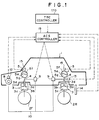
- Figure 1 is a schematic view showing an active suspension system,
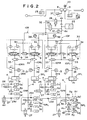
- Figure 2 shows the hydraulic circuit for the active suspension system,
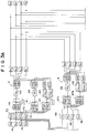
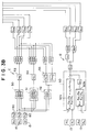
- Figures 3A and 3B show the operation of the controller for controlling the suspension properties,
- Figure 4 is a schematic view showing a traction control system,
- Figure 5 is a time chart for illustrating the operation of the TRC controller which is executed on the engine and the brake during the traction control,
- Figure 6 shows a circuit for determining the target slip values with respect to the engine control and the brake control,
- Figure 7 is a flow chart for illustrating the active suspension control on the basis of the TRC signal, and
- Figures 8 to 10 show modifications of the active suspension control on the basis of the TRC signal.
- In Figure 1,
reference numerals fluid cylinder 3 is connected between each wheel and thevehicle body 1. Thefluid cylinder 3 comprises acylinder body 3a and apiston 3b which is received in thecylinder body 3a and forms aliquid pressure chamber 3c in thecylinder body 3a. Thepiston 3b is connected to apiston rod 3d the upper end of which is connected to thevehicle body 1. Thecylinder body 3a is connected to the wheel at the lower end thereof. - A
gas spring 5 is connected to theliquid pressure chamber 3c of eachfluid cylinder 3 by way of a communicatingpassage 4. The inner space of eachgas spring 5 is divided into agas chamber 5f and aliquid pressure chamber 5g by adiaphragm 5e, and theliquid pressure chamber 5g is communicated with theliquid pressure chamber 3c of thefluid cylinder 3. - Each
fluid cylinder 3 is connected to ahydraulic pump 8 by way of aliquid pressure passage 10. A proportionalflow control valve 9 which is provided in theliquid pressure passage 10 for eachfluid cylinder 3 controls feed and discharge of hydraulic fluid to and from theliquid pressure chamber 3c of thefluid cylinder 3. - A
discharge pressure sensor 12 detects the discharge pressure of thehydraulic pump 8,liquid pressure sensors 13 detect the liquid pressure in theliquid pressure chambers 3c of therespective fluid cylinders 3c, andvehicle level sensors 14 detect the vehicle levels at the respective wheels (cylinder stroke). Further threevertical acceleration sensors 15 which detect the vertical acceleration of the vehicle body (vertical acceleration of the vehicle body on the wheels) are provided substantially on the same horizontal plane, two above the respectivefront wheels 2F and the other at the center between therear wheels 2R. The detecting signals of these sensors are input into anACS controller 19 which may be of a CPU, for instance, and thecontroller 19 changes the suspension properties on the basis of the detecting signals. - The hydraulic pressure circuit which controls feed and discharge of the hydraulic fluid to and from the
liquid pressure chambers 3c of thefluid cylinders 3 is shown in Figure 2. In Figure 2, thehydraulic pump 8 is connected to ahydraulic pump 21 for a power steering system so that they form a two-throw pump. Thehydraulic pump 21 is driven by amotor 20. Thedischarge line 8a of thehydraulic pump 8 is provided with anaccumulator 22. A front wheel side passage 10F and a rearwheel side passage 10R are connected to thedischarge line 8a in parallel downstream of theaccumulator 22. The front wheel side passage 10F branches into left and right front wheel side passages 10FL and 10FR which are respectively communicated with theliquid pressure chambers 3c of the fluid cylinders 3FL and 3FR for the left and right front wheels. The rearwheel side passage 10R branches into left and right rear wheel side passages 10RL and 10RR which are respectively communicated with theliquid pressure chambers 3c of the fluid cylinders 3RL and 3RR for the left and right rear wheels. - Gas spring groups 5FL, 5FR, 5RL and 5RR each consisting of four
gas springs 5a to 5d are respectively communicated with theliquid pressure chambers 3c of thecorresponding fluid cylinders 3 by way of communicatingpassages 4. Thegas springs 5a to 5d are connected to the communicatingpassage 4 in parallel by way of branch communicating passages 4a to 4d respectively havingorifices 25a to 25d. Theorifices 25a to 25d exhibit attenuating effect and the gas in thegas chambers 5f of thegas springs 5a to 5d exhibit damping effect. - An
attenuation changing valve 26 for changing the effective cross-sectional area of the communicatingpassage 4 is provided in the communicatingpassage 4 between the first andsecond gas springs attenuation changing valve 26 moves between an open position where it wide opens the communicatingpassage 4 and a closed position where it substantially narrows the effective cross-sectional area of the communicatingpassage 4. When the vehicle turns, theattenuation changing valve 26 is moved to the closed position and restrains hydraulic fluid from flowing into and out theliquid pressure chambers 5g of the second andthird gas springs liquid pressure chambers 3c of thefluid cylinders 3 and improving to control. - A
switching valve 27 which is movable between an open position and a closed position is provided in the branch communicating passage 4d. When theswitching valve 27 is in the open position, hydraulic fluid can flow into and out theliquid pressure chamber 5g of thefourth gas spring 5d and the suspension is soft. On the other hand, when theswitching valve 27 is in the closed position, hydraulic fluid is restrained from flowing into and out theliquid pressure chamber 5g of thefourth gas spring 5d and the suspension is hard. - An
unload relief valve 28 is connected to thedischarge passage 8a of thehydraulic pump 8 near theaccumulator 22. Therelief valve 28 is movable between an open position and a closed position. When the discharge pressure of thepump 8 as detected by thedischarge pressure sensor 12 exceeds an upper limit, therelief valve 28 is opened to return hydraulic fluid from thepump 8 to areservoir 29, thereby fixing the pressure of hydraulic fluid in theaccumulator 22 to a preset value. To each of thefluid cylinders 3 is fed the hydraulic fluid accumulated in theaccumulator 22. - Since the arrangements for the left front wheel, the right front wheel, the left rear wheel and the right rear wheel are the same, only the arrangement for the left front wheel will be described here. The left front wheel side passage 10FL is provided with said proportional
flow control valve 9. The proportionalflow control valve 9 is movable among a cutoff position in which it closes all the ports thereof, a feed position in which it opens the left front wheel side passage 10FL, and a discharge position in which it communicates the fluid cylinder side portion of the left front wheel side passage 10FL with areturn passage 32. Further the proportionalflow control valve 9 has a built-inpressure compensating valve 9a which holds the hydraulic pressure in the fluid cylinder 3FL constant at a predetermined value when theflow control valve 9 is in the feed position or the discharge position. - On the fluid cylinder side of the proportional
flow control valve 9, there is provided a pilot pressure responsive on-offvalve 33 which opens and closes the left front wheel side passage 10FL. When asolenoid valve 34 opens, the hydraulic pressure in the left front wheel side passage 10FL on the hydraulic pump side of the proportionalflow control valve 9 is applied to the on-offvalve 33 as the pilot pressure. When the pilot pressure is not lower than a predetermined value, the on-offvalve 33 opens the left front wheel side passage 10FL to permit the proportionalflow control valve 9 to control the flow rate to the fluid cylinder 3FL. On the other hand, when the on-offvalve 33 closes, the left front wheel side passage 10FL is closed in the liquid-tight fashion and prevents hydraulic fluid from flowing out theliquid pressure chamber 3c of the fluid cylinder 3FL. - In Figure 2,
reference numeral 35 denotes a relief valve which opens and returns hydraulic fluid to thereturn passage 32 when the pressure in theliquid pressure chamber 3c of the fluid cylinder 3FL becomes abnormally high.Reference numeral 36 denotes a valve which is connected to thedischarge passage 8a of thehydraulic pump 8 near theaccumulator 22 and is interlocked with the ignition key. Thevalve 36 is opened after the ignition key is turned off and returns hydraulic fluid in theaccumulator 22 to thereservoir 29.Reference numeral 37 denotes an in-pump relief valve which returns hydraulic fluid to thereservoir 29 when the discharge pressure of thehydraulic pump 8 becomes abnormally high.Reference numeral 38 denotes a return accumulator which is connected to thereturn passage 32 and accumulates the hydraulic pressure when hydraulic fluid is discharged from thefluid cylinder 3. - Now the operation of the
controller 19 for controlling the suspension properties or controlling feed and discharge of hydraulic fluid to and from theliquid pressure chamber 3c of thefluid cylinder 3 will be described with reference to Figures 3A and 3B. - In Figures 3A and 3B, a control system A controls the vehicle level to a target level on the basis of the detecting signals (vehicle level displacement signals) XFR, XFL, XRR and XRL of the
vehicle level sensors 14 for the respective wheels, a control system B suppresses the vehicle level displacement speed on the basis of vehicle level displacement speed signals YFR, YFL, YRR and YRL which are obtained by differentiating the vehicle level displacement signals XFR, XFL, XRR and XRL, a control system C suppresses vertical vibrations of the vehicle body on the basis of the detecting signals (vertical acceleration signals) GFR, GFL and GR of the threevertical acceleration sensors 15, and a control system D calculates warp of the vehicle body on the basis of the detecting signals (pressure signals) PFR, PFL, PRR and PRL of theliquid pressure sensors 13 and suppresses the warp of the vehicle body. - In the control system A, a bounce
component calculating section 40 calculates the bounce component of the vehicle body by adding the vehicle level displacement signals XFR and XFL for thefront wheels 2F, and adding the vehicle level displacement signals XRR and XRL for therear wheels 2R. A pitchcomponent calculating section 41 subtracts the sum of the vehicle level displacement signals XRR and XRL for therear wheels 2R from the sum of the vehicle level displacement signals XFR and XFL for thefront wheels 2F and calculates the pitch component of the vehicle body. A rollcomponent calculating section 42 calculates the roll component of the vehicle body by adding the difference between the vehicle level displacement signals XFR and XFL for thefront wheels 2F (XFR-XFL) and the difference between the vehicle level displacement signals XRR and XRL for therear wheels 2R (XRR-XRL). - The bounce component of the vehicle body calculated by the bounce
component calculating section 40 and a target average vehicle level TH are input into abounce control section 43 which calculates, on the basis of gain KB1, the amount of hydraulic fluid to be fed to theliquid pressure chambers 3c of therespective fluid cylinders 3 for the bounce control. The pitch component of the vehicle body calculated by the pitchcomponent calculating section 41 is input into apitch control section 44 which calculates, on the basis of gain KP1, the amount of hydraulic fluid to be fed to theliquid pressure chambers 3c of therespective fluid cylinders 3 for the pitch control. The roll component of the vehicle body calculated by the rollcomponent calculating section 42 and a target roll displacement TR are input into aroll control section 43 which calculates, on the basis of gains KRF1 and KRR1, the amount of hydraulic fluid to be fed to theliquid pressure chambers 3c of therespective fluid cylinders 3 for the roll control so that the vehicle level becomes a value corresponding to the target roll displacement TR. - The control variables calculated by the
bounce control section 43, thepitch control section 44 and theroll control section 45 are inverted in their signs for each wheel, that is, the signs of the control variables are inverted for each wheel so that they become opposite to the sign of the vehicle level displacement signal (XFR, XFL, XRR or XRL) detected by thevehicle level sensor 14 for the wheel. Thereafter, the control variables for the bounce control, the pitch control and the roll control with the inverted signs are added together, and flow rate signals QFR1, QFL1, QRR1 and QRL1 for theflow control valves 9 for the respective wheels in the control system A are obtained. -
Dead zone devices 70 are inserted between each vehicle speed sensor and the bouncecomponent calculating section 40, the pitchcomponent calculating section 41 and the rollcomponent calculating section 42, and the vehicle level displacement signals XFR, XFL, XRR and XRL from thevehicle level sensors 14 are input into the bouncecomponent calculating section 40, the pitchcomponent calculating section 41 and the rollcomponent calculating section 42 only when they exceed a preset dead zone XH. - The control system B has four differentiators which differentiate the vehicle level displacement signals XFR, XFL, XRR and XRL and calculates the vehicle level displacement speed signals YFR, YFL, YRR and YRL according to the following formula wherein Xn stands for the vehicle level displacement at time t, Xn-1 stands for the vehicle level displacement at time t-1, and T stands for the sampling time.
- In the control system B, a pitch component calculating section 47a subtracts the sum of the vehicle level displacement speed signals YRR and YRL for the
rear wheels 2R from the sum of the vehicle level displacement speed signals YFR and YFL for thefront wheels 2F and calculates the pitch component of the vehicle body. A rollcomponent calculating section 47b calculates the roll component of the vehicle body by adding the difference between the vehicle level displacement speed signals YFR and YFL for thefront wheels 2F (YFR-YFL) and the difference between the vehicle level displacement speed signals YRR and YRL for therear wheels 2R (YRR-YRL). - The pitch component of the vehicle body calculated by the pitch component calculating section 47a is input into a
pitch control section 48 which calculates, on the basis of gain KP2, the flow control variable for controlling the flow rate of hydraulic fluid to each of the proportionalflow control valves 9 for the pitch control. The roll component of the vehicle body calculated by the rollcomponent calculating section 47b is input into aroll control section 49 which calculates, on the basis of gains KRF2 and KRR2, the flow rate of hydraulic fluid to each of the proportionalflow control valves 9 for the roll control. - The control variables calculated by the
pitch control section 48 and theroll control section 49 are inverted in their signs for each wheel, that is, the signs of the control variables are inverted for each wheel so that they become opposite to the sign of the vehicle level displacement speed signal (YFR, YFL, YRR or YRL) calculated by thedifferentiator 46 for the wheel. Thereafter, the control variables for the pitch control and the roll control with the inverted signs are added together, and flow rate signals QFR2, QFL2, QRR2 and QRL2 for theflow control valves 9 for the respective wheels in the control system B are obtained. - In the control system C, a bounce
component calculating section 50 adds up the outputs GFR, GFL and GR of thevertical acceleration sensors 15 and calculates the bounce component of the vehicle body. A pitchcomponent calculating section 51 subtracts the output GR of thevertical acceleration sensor 15 which is disposed at the center between therear wheels 2R from half of the sum of the outputs of thevertical acceleration sensors 15 above thefront wheels 2F and calculates the pitch component of the vehicle body. A rollcomponent calculating section 52 calculates the roll component of the vehicle body by subtracting the output GFL of thevertical acceleration sensor 15 above the left front wheel from the output GFR of thevertical acceleration sensor 15 above the right front wheel. The bounce component of the vehicle body calculated by the bouncecomponent calculating section 50 is input into abounce control section 53 which calculates, on the basis of gain KB3, the flow control variable for controlling the flow rate of hydraulic fluid to each of the proportionalflow control valves 9 for the bounce control. The pitch component of the vehicle body calculated by the pitchcomponent calculating section 51 is input into apitch control section 54 which calculates, on the basis of gain KP3, the flow control variable for controlling the flow rate of hydraulic fluid to each of the proportionalflow control valves 9 for the pitch control. The roll component of the vehicle body calculated by the rollcomponent calculating section 52 is input into aroll control section 55 which calculates, on the basis of gains KRF3 and KRR3, the flow rate of hydraulic fluid to each of the proportionalflow control valves 9 for the roll control. - The control variables calculated by the
bounce control section 53, thepitch control section 54 and theroll control section 55 are inverted in their signs for each wheel, and the control variables for bounce control, the pitch control and the roll control with the inverted signs are added together, whereby flow rate signals QFR3, QFL3, QRR3 and QRL3 for theflow control valves 9 for the respective wheels in the control system C are obtained. -
Dead zone devices 80 are inserted between eachvertical acceleration sensor 15 and the bouncecomponent calculating section 50, the pitchcomponent calculating section 51 and the rollcomponent calculating section 52, and the vertical acceleration signals GFR, GFL and GR from thevertical acceleration sensors 15 are input into the bouncecomponent calculating section 50, the pitchcomponent calculating section 51 and the rollcomponent calculating section 52 only when they exceed a preset dead zone XG. - In the control system D, a
warp control section 60 is provided with a front wheel side liquid pressureratio calculating section 60a and a rear wheel side liquid pressureratio calculating section 60b. The front wheel side liquid pressureratio calculating section 60a receives liquid pressure detecting signals PFL and PFR from theliquid pressure sensors 13 for detecting the liquid pressures in thefluid cylinders 3 for the left and rightfront wheels 2F, and calculates the liquid pressure ratio Pf which is the ratio of the difference between the liquid pressures in thefluid cylinders 3 for the left and right front wheels (PFR-PFL) to the sum of the same (PFR+PFL), that is,
ratio calculating section 60a outputs the liquid pressure ratio Pf as it is when -ωL<Pf<ωL wherein ωL stands for a threshold liquid pressure ratio and outputs the threshold liquid pressure ratio -ωL when Pf<-ωL, and outputs the threshold liquid pressure ratio ωL when Pf>ωL. The rear wheel side liquid pressureratio calculating section 60b receives liquid pressure detecting signals PRL and PRR from theliquid pressure sensors 13 for detecting the liquid pressures in thefluid cylinders 3 for the left andright wheels 2R, and calculates the liquid pressure ratio Pr which is the ratio of the difference between the liquid pressures in thefluid cylinders 3 for the left and right rear wheels (PRR-PRL) to the sum of the same (PRR+PRL), that is,
- The
warp control section 60 multiplies the liquid pressure ratio Pr for the rear wheels by a predetermined value which is determined on the basis of gain ωF and subtracts the product from the liquid pressure ratio Pf for the front wheels. The output of thewarp control section 60 is multiplied by a predetermined value which is determined on the basis of gain ωA. For the front wheels, the output of thewarp control section 60 multiplied by the predetermined value is further multiplied by a predetermined value determined on the basis of gain ωC. The values thus obtained for the left wheels or right wheels are inverted in their signs so that the values for the left wheels and the right wheels are opposite to each other in sign, whereby flow rate signals QFR4, QFL4, QRR4 and QRL4 for theflow control valves 9 for the respective wheels in the control system D are obtained. - The flow rate signals for the
flow control valves 9 in the control systems A to D obtained in the manner described above are added together for each wheel, thereby obtaining final flow rate signals QFR, QFL, QRR and QRL for theflow control valves 9. - The following table shows an example of a control gain map which is stored in the
controller 19 and in which the control gains which are used in the control systems A to D are related to the operating conditions of the vehicle. In this particular embodiment, the operating conditions of the vehicle are divided into seven modes.
- In the table,
mode 1 shows the control gains to be used for 60 seconds after the engine stops.Mode 2 shows the control gains to be used when the vehicle speed is zero though the ignition is on.Mode 3 shows the control gains to be used when the vehicle travels straight with the lateral acceleration not larger than 0.1.Mode 4 shows the control gains to be used when the vehicle is making a gentle turn with the lateral acceleration larger than 0.1 and not larger than 0.3.Mode 5 shows the control gains to be used when the vehicle is making a moderate turn with the lateral acceleration larger than 0.3 and not larger than 0.5. Mode 6 shows the control gains to be used when the vehicle is making a sharp turn with the lateral acceleration larger than 0.5. Mode 7 shows the control gains to be used instead of those formode 4 when the vehicle is making a gentle turn with the lateral acceleration larger than 0.1 and not larger than 0.3 while reverse roll mode has been selected by a roll mode selection switch (not shown). When the vehicle speed becomes not lower than 120Km/h, the mode is forcibly switched tomode 4 even if the reverse roll mode has been selected. In the table, QMAX stands for a maximum flow rate control variable to be fed to the proportionalflow control valve 9 for each wheel, and PMAX stands for a maximum pressure in theliquid pressure chamber 3c of thefluid cylinder 3. The maximum pressure PMAX is set so that hydraulic fluid does not reverse from theliquid pressure chamber 3c to theaccumulator 22. PMIN stands for a minimum pressure in theliquid pressure chamber 3c of thefluid cylinder 3. The minimum pressure PMIN is set so that the pressure in theliquid pressure chamber 3c is not excessively lowered and the gas springs 5 are not damaged. Further, in the table, each arrow indicates that values are the same as the value to which the arrow is directed. Except mode 7, the control gains are set so that the running stability of the vehicle body is improved as the mode number increases. - Figure 4 schematically shows a vehicle provided with a TRC system. In this particular example, left and right front wheels 2FL and 2FR are driven wheels and left and right rear wheels 2RL and 2RR are driving wheels. An
engine 102 is mounted at the front of the vehicle body, and the output torque of theengine 102 is transmitted to the left rear wheel 2RL through anautomatic transmission 103, apropeller shaft 104, adifferential gear 105 and aleft driving axle 106L, and to the right rear wheel 2RR through theautomatic transmission 103, thepropeller shaft 104, thedifferential gear 105 and aright driving axle 106R. - The
automatic transmission 103 comprises a torque converter 111 and atransmission gear mechanism 112. Thetransmission gear mechanism 112 is hydraulically operated and has four forward speeds and one reverse speed in this particular example. Theautomatic transmission 103 is shifted by selectively energizing and de-energizing a plurality of solenoids 113a in the hydraulic circuit. The torque converter 111 has a lockup clutch 111a which is applied or released by energizing or de-energizing asolenoid 113b in the hydraulic circuit. - The
solenoids 113a and 113b are controlled by an AT (automatic transmission) controller 160. A throttle opening signal from athrottle opening sensor 161 which detects the opening of the throttle valve and a vehicle speed signal from avehicle speed sensor 162 which detects the vehicle speed (represented by the rotational speed of thepropeller shaft 104 in this embodiment) are input into the AT controller 160. - The wheels 2FL, 2FR, 2RL and 2RR are respectively provided with brakes 121FL, 121FR, 121RL and 121RR. Brake fluid pressure is applied to calipers (wheel cylinder) 122FL, 122FR, 122RL and 122RR for the brakes by way of brakes pipes 123FL, 123FR, 123RL and 123RR. The brake lines are as follows.
- Brake pedal (125) depressing force is multiplied by a liquid-pressure-operated
booster 126 and then transmitted to a tandem master cylinder 127. The brake pipe 123FL for the left front wheel is connected to a first discharge port 127a of the master cylinder 127, and the brake pipe 123FR for the right front wheel is connected to a second discharge port 127b. Liquid pressure is fed to thebooster 126 from apump 129 through apipe 128, and excess liquid pressure is returned to areservoir 131 through areturn pipe 130. Abranch pipe 128a which branches off from thepipe 128 communicates with a junction a which will be described later, and is provided with a solenoid on-offvalve 132. Boosting pressure produced in thebooster 126 is fed to said junction a through apipe 133 which is also provided with a solenoid on-offvalve 134. Acheck valve 135 which permits brake fluid to flow only toward the junction a is connected to thepipe 133 in parallel to the on-offvalve 134. - The brake pipes 123RL and 123RR for the left and right rear wheels are connected to the junction a. The brake pipes 123RL and 123RR are respectively provided with solenoid on-off
valves 136A and 137A. Arelief passage 138L is connected to the brake pipes 123RL downstream of the on-off valve 136A and a solenoid on-offvalve 136B is provided in therelief passage 138L. Similarly, arelief passage 138R is connected to the brake pipes 123RR downstream of the on-offvalve 137A and a solenoid on-offvalve 137B is provided in therelief passage 138R. - The on-off
valves TRC controller 170 for traction control. When the traction control is not effected, the on-offvalve 132 is closed, the on-offvalve 134 is opened, the on-offvalves valves 136A and 137A are opened as shown in Figure 4. When thebrake pedal 125 is pushed down in this state, brake fluid pressure is applied to the brakes 121FL and 121FR for the front wheels through the master cylinder 127 and boosting pressure is applied to the brakes 121RL and 121RR for the rear wheels as the brake fluid pressure by thebooster 126 according the brake pedal depressing force. - When the slip of the driving wheels (rear wheels 2RL and 2RR) relative to road surface becomes large and the traction control is effected as will be described later, the on-off
valve 134 is closed and the on-offvalve 132 is opened. Then by duty control of the on-offvalves 136A and 136B (137A and 137B), the brake fluid pressure is held constant, increased or lowered. More particularly, with the on-offvalve 132 kept open, the brake fluid pressure is held constant when the on-offvalves valve 136B (137B) is opened, and is lowered when the on-off valve 136A (137A) is closed and the on-offvalve 136B (137B) is opened. The brake fluid pressure which has been transmitted through thebranch passage 128a does not act on thebrake pedal 125 as counterforce by virtue of thecheck valve 135. - When the
brake pedal 125 is pushed down while such traction control is being effected, brake fluid pressure the value of which depends upon the amount of depression of thebrake pedal 125 is applied to the brakes 121RL and 121RR for the rear wheels from thebooster 126 through thecheck valve 135. - The
TRC controller 170 brakes the rear wheels 2RL and 2RR in order to reduce the driving torque thereof and at the same time reduces the output torque of theengine 102. For this purpose, a throttleopening controlling mechanism 145 is inserted into aninterlocking mechanism 144 which interlocks athrottle valve 142 disposed in anintake passage 141 of theengine 102 with anaccelerator pedal 143. The throttleopening controlling mechanism 145 is driven by anelectric motor 145a, and while themotor 145a is off, the opening of thethrottle valve 142 is solely depend on the amount of depression of the accelerator pedal 143 (i.e., the throttle opening changes from 0% to 100% as the amount of depression of the accelerator pedal changes from 0% to 100%). While themotor 145a is on, the throttle opening is caused to be 0 when the amount of depression of theaccelerator pedal 143 is not larger than a predetermined value, and is increased from 0 with increase in the amount of depression of theaccelerator pedal 143 when the amount of depression of theaccelerator pedal 143 is larger than the predetermined value. - During the traction control, the
TRC controller 170 controls the brakes, the engine output (by controlling themotor 145a which drives the throttle opening controlling mechanism 145) and the lockup of the automatic transmission 103 (by way of the AT controller 160). In addition to the signals from thethrottle opening sensor 161 and thevehicle speed sensor 162, wheel speed signals from wheel speed sensors 166FL, 166FR, 166RL and 166RR which detect the rotational speeds of the wheels 2FL, 2FR, 2RL and 2RR, an accelerator depression signal from anaccelerator depression sensor 167 which detects the amount of depression of theaccelerator pedal 143, a motor operation signal from amotor operation sensor 168 which detects the state of operation of themotor 145a (i.e., the throttle opening depending on the operation of themotor 145a), a steering angle signal from asteering angle sensor 169 which detects the turning angle of the steering wheel, a mode signal from aswitch 171 which is manually operated, and a brake signal from abrake switch 172 which is turned on when thebrake pedal 125 is pushed down. - Figure 5 shows the operation of the
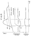
TRC controller 170 which is executed on the engine and the brake during the traction control. In Figure 5 a target value (a target slip value of the driving wheels) with respect to the engine is denoted by SET and a target value with respect to the brake is denoted by SBT. (SBT>SET) - Until time t1, a target throttle opening Tn is set to a basic throttle opening TH·B corresponding to the actual amount of depression of the accelerator pedal since slip of the driving wheels is not so large.
- At the time t1, slip of the driving wheels increases to the target value SET with respect to the engine (will be referred to as "the engine target value SET", hereinbelow). In this embodiment, the traction control is commenced when slip of the driving wheels exceeds the engine target value SET, and at the time t1, the throttle opening is directly reduced to a lower limit control value SM (feed-forward control). After the throttle opening is once reduced to the lower limit control value SM, the throttle opening is feedback-controlled so that slip of the driving wheels converges on the engine target value SET. At this time, the target throttle opening Tn is set to TH·M (manipulating variable of the
motor 145a). (
- At time t2, slip of the driving wheels increases to the target value SBT with respect to the brake (will be referred to as "the brake target value SBT", hereinbelow). At the time t2, brake fluid pressure is applied to the brakes 121RL and 121RR for the driving wheels, that is, traction controls by the engine control and the brake control is commenced. The brake fluid pressure is feedback controlled so that slip of the driving wheels converges on the brake target value SBT.
- At time t3, slip of the driving wheels falls below the brake target value SBT, and after the time t3, the brake fluid pressure is gradually reduced to zero. The slip control by control of the engine is still continued.
- In this embodiment, the traction control is ended when the amount of depression of the accelerator pedal becomes zero.
- Figure 6 is block diagram for illustrating a circuit for determining the engine target value SET and the brake target value SBT. These values are determined according to the vehicle speed VS, the amount of depression of the accelerator pedal DP, the steering angle θ, the position of the
mode switch 171 and the maximum friction coefficient µmax of road surface. - In Figure 6, basic values STAO and STBO of the engine target value SET and the brake target value SBT are stored in a
map 181 as functions of the maximum friction coefficient µmax of road surface. (STBO>STAO) The engine target value SET and the brake target value SBT are obtained by multiplying the basic values STAO and STBO read out from themap 181 by correction gain coefficient KD. - The correction gain coefficient KD is obtained by multiplying gain coefficients VG, ACPG, STRG and MODEG together. The gain coefficient VG is stored in a
map 182 as a function of the vehicle speed VS. The gain coefficient ACPG is stored in amap 183 as a function of the amount of depression of the accelerator pedal DP. The gain coefficient STRG is stored in amap 184 as a function of the steering angle θ. The gain coefficient MODEG is manually selected by the driver and is stored in table 185. In the table 185, sport mode and normal mode are set. - In accordance with the present invention, as shown in Figure 1, the working signal (TRC signal) output from the
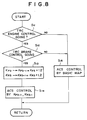
TRC controller 170 is input into theACS controller 19 and theACS controller 19 controls the properties of the active suspension (active suspension control) on the basis of the TRC signal. The active suspension control on the basis of the TRC signal is effected according to the flow chart shown in Figure 7. - In step S1, the
ACS controller 19 determines on the basis of the TRC signal whether the traction control is going on. When it is determined in step S1 that the traction control is not going on, theACS controller 19 controls the active suspension on the basis of the control gains shown in the basic map (the aforesaid table) and then returns. On the other hand, when it is determined in step S1 that the traction control is going on, theACS controller 19 multiplies the control gains KP3, PR3 (KRF3, KRR3) of the control system C shown in the basic map by 1.2 and obtains increased control gains KP3-1 and KR3-1. (step S2) Then in step S3, theACS controller 19 controls the active suspension on the basis of the increased control gains KP3-1 and KR3-1. Thus, the control gain of the ACS control system is increased while the traction control is going on. - Thus in the active suspension control, the control gains KP3 and KR3 of the control system C are made larger than the normal when the traction control is going on. Accordingly, sinkage of the rear part of the vehicle (so-called squat) which occurs in response to commencement of the traction control can be effectively suppressed by quickly extending the
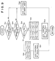
fluid cylinders 3 for the rear wheels by the active suspension control on the basis of the increased control gains, thereby improving the running stability. The reason the control gains KP3 and LR3 of the control system C which relate to the vertical vibration of the vehicle body are increased is increase of the control gains affects the driving comfort least. - Figures 8 to 10 show modifications of the active suspension control on the basis of the TRC signal. In the case of the modification shown in Figure 8, only when both the engine control and the brake control are being effected for the traction control, the control gains KP3 and KR3 of the control system C are increased (step S13) and the active suspension is controlled on the basis of the increased control gains KP3-1 and KR3-1. (step S14)
- In the case of the modification shown in Figure 9, when both the engine control and the brake control are being effected for the traction control, the control gains are increased according to the brake control variable BCV. That is, when the brake control variable BCV is not smaller than a predetermined value PBCV, the control gains KP3 and KR3 of the control system C and the control gains KP2 and KR2 of the control system B are multiplied by 1.3, and the active suspension is controlled on the basis of the increased control gains KP3-1, KR3-1, KP2-1 and KR2-1. (steps S24 and S25) On the other hand, when the brake control variable BCV is smaller than the predetermined value PBCV, only the control gains LP3 and KR3 of the control system C are multiplied by 1.2 and the active suspension is controlled on the basis of the increased control gains KP3-2 and KR3-2. (steps S26 and S27)
- In the case of the modification shown in Figure 10, the control gains KP3 and KR3 of the control system C are increased to different values when the brake control is effected for one of the left and right wheels and when the brake control is effected for both the left and right wheels. (steps S33 and S35)
Claims (8)
- Suspension-traction total control system for a vehicle (1) comprising a traction control system (TRC) which reduces driving torque for driving wheels of the vehicle (1) when the driving wheels slip and a suspension system (ACS) which has a hydraulic cylinder (3) disposed between the vehicle body and each of the wheels (2) of the vehicle (1) and in which the suspension properties are changed by controlling the hydraulic cylinders and can be changed when the traction control system (TRC) is operating,
characterized in that
the suspension system (ACS) includes a suspension control system which suppresses vibrations of the vehicle body (1) on the basis of the output of a means (15), arranged in said vehicle (1), for detecting acceleration of the vehicle body in a substantially vertical direction, and a control gain of said suspension control system related to said output is increased when the traction control system (TRC) is operating. - A suspension-traction total control system as defined in claim 1 in which said suspension control system suppresses vertical vibrations of the vehicle body on the basis of detecting signals of vertical acceleration sensors (15) which detect vertical accelerations of the vehicle body on the wheels.
- A suspension-traction total control system as defined in claim 1 or 2 in which said traction control system (TRC) controls at least one of the engine (102) and the brakes (121) for the wheels of the vehicle in order to reduce the driving torque, and the control gain of the suspension control system is increased when the traction control system is controlling both the engine and the brakes.
- A suspension-traction total control system as defined in claim 3 in which the suspension system (ACS) further includes a second control system which suppresses the vehicle level displacement speed on the basis of vehicle level displacement speed signals (XFR, XFL, XRR, XRL) which are obtained by differentiating outputs of vehicle level sensors (14) provided for the respective wheels, and both the control gains of the suspension control system and the second control system are increased when the traction control system (TRC) is controlling both the engine and the brakes and the value of a brake control variable (BCV) is not smaller than a predetermined value (PBCV).
- A suspension-traction total control system as defined in claim 3 in which only the control gain of the suspension control system is increased when the traction control system (TRC) is controlling both the engine and the brakes and the value of a brake control variable (BCV) is smaller than a predetermined value (PBCV).
- A suspension-traction total control system as defined in claim 5 in which the control gain of the suspension control system is increased, when the traction control system (TRC) is controlling both the engine and the brakes and the value of the brake control variable is smaller than the predetermined value, by a smaller value than when the traction control system is controlling both the engine and the brakes and the value of the brake control variable is not smaller than the predetermined value.
- A suspension-traction total control system as defined in claim 3 in which the control gain of the suspension control system is increased to different values when the traction control system (TRC) is controlling the brakes for one of the left and right wheels and when the traction control system is controlling the brakes for both the left and right wheels.
- A suspension-traction total control system as defined in claim 1 in which the suspension properties are changed by controlling feed and charge of the hydraulic fluid to and from the hydraulic cylinders (3).
Applications Claiming Priority (4)
| Application Number | Priority Date | Filing Date | Title |
|---|---|---|---|
| JP238181/89 | 1989-09-13 | ||
| JP23818189 | 1989-09-13 | ||
| JP2074516A JP2945705B2 (en) | 1989-09-13 | 1990-03-23 | Total control system for suspension and driving force |
| JP74516/90 | 1990-03-23 |
Publications (3)
| Publication Number | Publication Date |
|---|---|
| EP0417792A2 EP0417792A2 (en) | 1991-03-20 |
| EP0417792A3 EP0417792A3 (en) | 1993-04-28 |
| EP0417792B1 true EP0417792B1 (en) | 1997-03-05 |
Family
ID=26415664
Family Applications (1)
| Application Number | Title | Priority Date | Filing Date |
|---|---|---|---|
| EP90117669A Expired - Lifetime EP0417792B1 (en) | 1989-09-13 | 1990-09-13 | Suspension-traction total control system |
Country Status (3)
| Country | Link |
|---|---|
| EP (1) | EP0417792B1 (en) |
| JP (1) | JP2945705B2 (en) |
| DE (1) | DE69030041T2 (en) |
Cited By (12)
| Publication number | Priority date | Publication date | Assignee | Title |
|---|---|---|---|---|
| US5694321A (en) | 1994-11-25 | 1997-12-02 | Itt Automotive Europe Gmbh | System for integrated driving stability control |
| US5701248A (en) | 1994-11-25 | 1997-12-23 | Itt Automotive Europe Gmbh | Process for controlling the driving stability with the king pin inclination difference as the controlled variable |
| US5711023A (en) | 1994-11-25 | 1998-01-20 | Itt Automotive Europe Gmbh | System for determining side slip angle |
| US5711024A (en) | 1994-11-25 | 1998-01-20 | Itt Automotive Europe Gmbh | System for controlling yaw moment based on an estimated coefficient of friction |
| US5710705A (en) | 1994-11-25 | 1998-01-20 | Itt Automotive Europe Gmbh | Method for determining an additional yawing moment based on side slip angle velocity |
| US5710704A (en) | 1994-11-25 | 1998-01-20 | Itt Automotive Europe Gmbh | System for driving stability control during travel through a curve |
| US5732379A (en) | 1994-11-25 | 1998-03-24 | Itt Automotive Europe Gmbh | Brake system for a motor vehicle with yaw moment control |
| US5732378A (en) | 1994-11-25 | 1998-03-24 | Itt Automotive Europe Gmbh | Method for determining a wheel brake pressure |
| US5732377A (en) | 1994-11-25 | 1998-03-24 | Itt Automotive Europe Gmbh | Process for controlling driving stability with a yaw rate sensor equipped with two lateral acceleration meters |
| US5742507A (en) | 1994-11-25 | 1998-04-21 | Itt Automotive Europe Gmbh | Driving stability control circuit with speed-dependent change of the vehicle model |
| US5774821A (en) | 1994-11-25 | 1998-06-30 | Itt Automotive Europe Gmbh | System for driving stability control |
| US10507825B2 (en) | 2016-11-08 | 2019-12-17 | Ford Global Technologies, Llc | Vehicle pitch control during a stop |
Families Citing this family (6)
| Publication number | Priority date | Publication date | Assignee | Title |
|---|---|---|---|---|
| GB9119103D0 (en) * | 1991-09-07 | 1991-10-23 | Motor Ind Res Ass | Suspension system |
| FR2714642B1 (en) * | 1994-01-04 | 1996-03-08 | Peugeot | Traction control device for a motor vehicle. |
| JPH106951A (en) * | 1996-04-26 | 1998-01-13 | Toyota Motor Corp | Controller for vehicle |
| US6219602B1 (en) | 1999-04-01 | 2001-04-17 | Delphi Technologies, Inc. | Vehicle suspension control with stability in turn enhancement |
| US6181997B1 (en) * | 1999-04-01 | 2001-01-30 | Delphi Technologies, Inc. | Vehicle suspension control with compensation for yaw correcting active brake control |
| SE0202852L (en) * | 2002-09-27 | 2003-07-08 | Scania Cv Abp | Procedure and device for power adaptation |
Family Cites Families (6)
| Publication number | Priority date | Publication date | Assignee | Title |
|---|---|---|---|---|
| JPS62110529A (en) * | 1985-11-08 | 1987-05-21 | Nissan Motor Co Ltd | Differential limiting controller for vehicle |
| DE3768968D1 (en) * | 1986-01-30 | 1991-05-08 | Toyota Motor Co Ltd | CONTROL METHOD FOR VEHICLE BEHAVIOR. |
| EP0264944B1 (en) * | 1986-10-24 | 1993-01-13 | Mazda Motor Corporation | Vehicle suspension system having variable suspension properties |
| DE3738284A1 (en) * | 1986-12-09 | 1988-06-30 | Bosch Gmbh Robert | DEVICE FOR ACTIVE CHASSIS CONTROL IN MOTOR VEHICLES |
| DE3731228A1 (en) * | 1987-09-17 | 1989-03-30 | Teves Gmbh Alfred | ADJUSTABLE VIBRATION DAMPER |
| JPH0195922A (en) * | 1987-10-08 | 1989-04-14 | Mazda Motor Corp | Suspension control device for vehicle |
-
1990
- 1990-03-23 JP JP2074516A patent/JP2945705B2/en not_active Expired - Fee Related
- 1990-09-13 EP EP90117669A patent/EP0417792B1/en not_active Expired - Lifetime
- 1990-09-13 DE DE69030041T patent/DE69030041T2/en not_active Expired - Fee Related
Cited By (14)
| Publication number | Priority date | Publication date | Assignee | Title |
|---|---|---|---|---|
| US5694321A (en) | 1994-11-25 | 1997-12-02 | Itt Automotive Europe Gmbh | System for integrated driving stability control |
| US5701248A (en) | 1994-11-25 | 1997-12-23 | Itt Automotive Europe Gmbh | Process for controlling the driving stability with the king pin inclination difference as the controlled variable |
| US5711023A (en) | 1994-11-25 | 1998-01-20 | Itt Automotive Europe Gmbh | System for determining side slip angle |
| US5711024A (en) | 1994-11-25 | 1998-01-20 | Itt Automotive Europe Gmbh | System for controlling yaw moment based on an estimated coefficient of friction |
| US5710705A (en) | 1994-11-25 | 1998-01-20 | Itt Automotive Europe Gmbh | Method for determining an additional yawing moment based on side slip angle velocity |
| US5710704A (en) | 1994-11-25 | 1998-01-20 | Itt Automotive Europe Gmbh | System for driving stability control during travel through a curve |
| US5711025A (en) | 1994-11-25 | 1998-01-20 | Itt Automotive Europe Gmbh | Driving stability control system with selective brake actuation |
| US5732379A (en) | 1994-11-25 | 1998-03-24 | Itt Automotive Europe Gmbh | Brake system for a motor vehicle with yaw moment control |
| US5732378A (en) | 1994-11-25 | 1998-03-24 | Itt Automotive Europe Gmbh | Method for determining a wheel brake pressure |
| US5732377A (en) | 1994-11-25 | 1998-03-24 | Itt Automotive Europe Gmbh | Process for controlling driving stability with a yaw rate sensor equipped with two lateral acceleration meters |
| US5742507A (en) | 1994-11-25 | 1998-04-21 | Itt Automotive Europe Gmbh | Driving stability control circuit with speed-dependent change of the vehicle model |
| US5774821A (en) | 1994-11-25 | 1998-06-30 | Itt Automotive Europe Gmbh | System for driving stability control |
| US5862503A (en) | 1994-11-25 | 1999-01-19 | Itt Automotive Europe Gmbh | System for driving stability control |
| US10507825B2 (en) | 2016-11-08 | 2019-12-17 | Ford Global Technologies, Llc | Vehicle pitch control during a stop |
Also Published As
| Publication number | Publication date |
|---|---|
| DE69030041D1 (en) | 1997-04-10 |
| JPH03176221A (en) | 1991-07-31 |
| EP0417792A3 (en) | 1993-04-28 |
| DE69030041T2 (en) | 1997-06-12 |
| JP2945705B2 (en) | 1999-09-06 |
| EP0417792A2 (en) | 1991-03-20 |
Similar Documents
| Publication | Publication Date | Title |
|---|---|---|
| US5183127A (en) | Suspension-traction total control system | |
| EP0417792B1 (en) | Suspension-traction total control system | |
| US5037119A (en) | Suspension-steering control apparatus | |
| EP0488052B1 (en) | Running state control system for a vehicle | |
| US5116078A (en) | Suspension control system cooperated with steering control system for vehicle | |
| WO1995011813A1 (en) | Vehicle suspension system | |
| EP0311114B1 (en) | Actively controlled suspension system for automotive vehicles with vehicular speed dependent variable damping characteristics | |
| US5100167A (en) | Suspension system for automotive vehicle | |
| US5176399A (en) | Suspension apparatus of automotive vehicle | |
| US5251134A (en) | Suspension system for automotive vehicle | |
| US5015006A (en) | Suspension apparatus of a vehicle | |
| US5218545A (en) | Suspension apparatus of automotive vehicle with control system having a variable time constant | |
| US4978135A (en) | Vehicle suspension system | |
| US5060969A (en) | Suspension apparatus of a vehicle | |
| JP2954606B2 (en) | Vehicle integrated control device | |
| JPH06122309A (en) | Suspension device for vehicle | |
| JP3059199B2 (en) | Electronically controlled hydraulic suspension | |
| JP3044091B2 (en) | Vehicle suspension device | |
| JPH09142118A (en) | Suspension control device | |
| JP3020656B2 (en) | Vehicle suspension device | |
| JP2839911B2 (en) | Vehicle suspension device | |
| JP3049148B2 (en) | Vehicle suspension device | |
| AU676785B2 (en) | Vehicle suspension system | |
| JP3096048B2 (en) | Vehicle suspension device | |
| JP3082859B2 (en) | Vehicle suspension device |
Legal Events
| Date | Code | Title | Description |
|---|---|---|---|
| PUAI | Public reference made under article 153(3) epc to a published international application that has entered the european phase |
Free format text: ORIGINAL CODE: 0009012 |
|
| AK | Designated contracting states |
Kind code of ref document: A2 Designated state(s): DE FR GB |
|
| PUAL | Search report despatched |
Free format text: ORIGINAL CODE: 0009013 |
|
| AK | Designated contracting states |
Kind code of ref document: A3 Designated state(s): DE FR GB |
|
| 17P | Request for examination filed |
Effective date: 19930817 |
|
| 17Q | First examination report despatched |
Effective date: 19930916 |
|
| GRAG | Despatch of communication of intention to grant |
Free format text: ORIGINAL CODE: EPIDOS AGRA |
|
| GRAH | Despatch of communication of intention to grant a patent |
Free format text: ORIGINAL CODE: EPIDOS IGRA |
|
| GRAH | Despatch of communication of intention to grant a patent |
Free format text: ORIGINAL CODE: EPIDOS IGRA |
|
| GRAA | (expected) grant |
Free format text: ORIGINAL CODE: 0009210 |
|
| AK | Designated contracting states |
Kind code of ref document: B1 Designated state(s): DE FR GB |
|
| REF | Corresponds to: |
Ref document number: 69030041 Country of ref document: DE Date of ref document: 19970410 |
|
| ET | Fr: translation filed | ||
| PGFP | Annual fee paid to national office [announced via postgrant information from national office to epo] |
Ref country code: FR Payment date: 19970716 Year of fee payment: 8 |
|
| PGFP | Annual fee paid to national office [announced via postgrant information from national office to epo] |
Ref country code: GB Payment date: 19970904 Year of fee payment: 8 |
|
| PLBE | No opposition filed within time limit |
Free format text: ORIGINAL CODE: 0009261 |
|
| STAA | Information on the status of an ep patent application or granted ep patent |
Free format text: STATUS: NO OPPOSITION FILED WITHIN TIME LIMIT |
|
| 26N | No opposition filed | ||
| PG25 | Lapsed in a contracting state [announced via postgrant information from national office to epo] |
Ref country code: GB Free format text: LAPSE BECAUSE OF NON-PAYMENT OF DUE FEES Effective date: 19980913 |
|
| GBPC | Gb: european patent ceased through non-payment of renewal fee |
Effective date: 19980913 |
|
| PG25 | Lapsed in a contracting state [announced via postgrant information from national office to epo] |
Ref country code: FR Free format text: LAPSE BECAUSE OF NON-PAYMENT OF DUE FEES Effective date: 19990531 |
|
| REG | Reference to a national code |
Ref country code: FR Ref legal event code: ST |
|
| PGFP | Annual fee paid to national office [announced via postgrant information from national office to epo] |
Ref country code: DE Payment date: 20011001 Year of fee payment: 12 |
|
| PG25 | Lapsed in a contracting state [announced via postgrant information from national office to epo] |
Ref country code: DE Free format text: LAPSE BECAUSE OF NON-PAYMENT OF DUE FEES Effective date: 20030401 |