EP0417931A1 - Heat-insulating piston - Google Patents
Heat-insulating piston Download PDFInfo
- Publication number
- EP0417931A1 EP0417931A1 EP90309426A EP90309426A EP0417931A1 EP 0417931 A1 EP0417931 A1 EP 0417931A1 EP 90309426 A EP90309426 A EP 90309426A EP 90309426 A EP90309426 A EP 90309426A EP 0417931 A1 EP0417931 A1 EP 0417931A1
- Authority
- EP
- European Patent Office
- Prior art keywords
- heat
- insulating
- head base
- piston according
- thin film
- Prior art date
- Legal status (The legal status is an assumption and is not a legal conclusion. Google has not performed a legal analysis and makes no representation as to the accuracy of the status listed.)
- Granted
Links
Images

Classifications
-
- F—MECHANICAL ENGINEERING; LIGHTING; HEATING; WEAPONS; BLASTING
- F02—COMBUSTION ENGINES; HOT-GAS OR COMBUSTION-PRODUCT ENGINE PLANTS
- F02F—CYLINDERS, PISTONS OR CASINGS, FOR COMBUSTION ENGINES; ARRANGEMENTS OF SEALINGS IN COMBUSTION ENGINES
- F02F3/00—Pistons
- F02F3/10—Pistons having surface coverings
- F02F3/12—Pistons having surface coverings on piston heads
-
- F—MECHANICAL ENGINEERING; LIGHTING; HEATING; WEAPONS; BLASTING
- F02—COMBUSTION ENGINES; HOT-GAS OR COMBUSTION-PRODUCT ENGINE PLANTS
- F02F—CYLINDERS, PISTONS OR CASINGS, FOR COMBUSTION ENGINES; ARRANGEMENTS OF SEALINGS IN COMBUSTION ENGINES
- F02F3/00—Pistons
- F02F3/0015—Multi-part pistons
- F02F3/003—Multi-part pistons the parts being connected by casting, brazing, welding or clamping
-
- F—MECHANICAL ENGINEERING; LIGHTING; HEATING; WEAPONS; BLASTING
- F05—INDEXING SCHEMES RELATING TO ENGINES OR PUMPS IN VARIOUS SUBCLASSES OF CLASSES F01-F04
- F05C—INDEXING SCHEME RELATING TO MATERIALS, MATERIAL PROPERTIES OR MATERIAL CHARACTERISTICS FOR MACHINES, ENGINES OR PUMPS OTHER THAN NON-POSITIVE-DISPLACEMENT MACHINES OR ENGINES
- F05C2251/00—Material properties
- F05C2251/04—Thermal properties
- F05C2251/042—Expansivity
-
- F—MECHANICAL ENGINEERING; LIGHTING; HEATING; WEAPONS; BLASTING
- F05—INDEXING SCHEMES RELATING TO ENGINES OR PUMPS IN VARIOUS SUBCLASSES OF CLASSES F01-F04
- F05C—INDEXING SCHEME RELATING TO MATERIALS, MATERIAL PROPERTIES OR MATERIAL CHARACTERISTICS FOR MACHINES, ENGINES OR PUMPS OTHER THAN NON-POSITIVE-DISPLACEMENT MACHINES OR ENGINES
- F05C2251/00—Material properties
- F05C2251/04—Thermal properties
- F05C2251/048—Heat transfer
-
- F—MECHANICAL ENGINEERING; LIGHTING; HEATING; WEAPONS; BLASTING
- F05—INDEXING SCHEMES RELATING TO ENGINES OR PUMPS IN VARIOUS SUBCLASSES OF CLASSES F01-F04
- F05C—INDEXING SCHEME RELATING TO MATERIALS, MATERIAL PROPERTIES OR MATERIAL CHARACTERISTICS FOR MACHINES, ENGINES OR PUMPS OTHER THAN NON-POSITIVE-DISPLACEMENT MACHINES OR ENGINES
- F05C2253/00—Other material characteristics; Treatment of material
- F05C2253/16—Fibres
Landscapes
- Engineering & Computer Science (AREA)
- Chemical & Material Sciences (AREA)
- Combustion & Propulsion (AREA)
- Mechanical Engineering (AREA)
- General Engineering & Computer Science (AREA)
- Pistons, Piston Rings, And Cylinders (AREA)
Abstract
Description
- This invention relates to a heat-insulating piston consisting of a composite structure containing a ceramic member and a heat-insulating member
- Conventionally, a heat-insulting piston is disclosed in Japanese Patent Laid-Open No. 302164/1988. This heat-insulating piston will be explained with reference to Fig. 6 of the accompanying drawings.
- This heat-insulating piston comprises a
piston head portion 41 having afitting boss portion 44 at is center and made of a material having a thermal expansion coefficient substantially equal to that of a ceramic material, and a metallicpiston skirt portion 42 having acenter fitting hole 52 to which thefitting boss portion 44 is fitted at its center. Thefitting boss portion 44 of thepiston head portion 41 and thecenter fitting hole 52 of thepiston skirt portion 42 are fixed to each other by metal flow of ametallic ring 51. A heat-insulatingbuffer material 48 as a heat-insulating gasket is interposed under a push state at the center contact portion between thepiston head portion 41 and thepiston skirt portion 42. A heat-insulatingair layer 49 is defined between thepiston head portion 41 and thepiston skirt portion 42. - Furthermore, a ceramic
thin sheet 45, which is formed to an extremely small thickness in order to reduce thermal capacity, is disposed on thepiston head portion 41 through a heat-insulatingmaterial 43 in such a manner as to face a combustion chamber. Aceramic ring 46 made of the same material as the ceramicthin sheet 45 is fitted to the outer peripheral portion of the latter, and these ceramicthin sheet 45 andceramic ring 46 are bonded at the contact portion by CVD (Chemical Vapor Deposition) as described in Japanese Patent Laid-Open No. 108171/1989 (U.S. Patent Specification No. 4,848,291), for example. - A
step portion 56 is formed on the inner peripheral surface of theceramic ring 46 and the outer peripheral portion of the piston head portion41 fits to theceramic ring 46 so as to come into contact with thestep portion 56 of theceramic ring 46. A heat-insulatingmaterial 43 is sealed into the space defined by the ceramicthin sheet 45, theceramic ring 46 and thepiston head portion 41. This heat-insulatingmaterial 43 is made of a material such as potassium titanate whiskers, zirconia fibers. When thepiston head portion 41 is fitted to thepiston skirt portion 42 under the push state, the outer peripheral portion of thepiston head portion 41 is pushed to thestep portion 56 of theceramic ring 46 and theceramic ring 46 is pushed to the peripheral portion of thepiston skirt portion 42. Acarbon seal 47 as a gasket is interposed in order to provide sealing between theceramic ring 46 and thepiston skirt portion 42. - In a heat-insulating engine member using a ceramic material as a heat-insulating or heat-resistant material such as a piston, it is extremely difficult to obtain sufficient heat-insulating characteristics. The ceramic material is kept under the state where it is exposed to high temperatures on the combustion chamber side and there exist the problems, therefore, that the ceramic material receives a thermal shock and its strength is not sufficient. If the thickness of the ceramic material on the wall surface is increased for the purpose of heat insulation, a thermal capacity becomes greater and there occur the problems that intake air receives a greater quantity of heat from the combustion chamber and is heated to high temperatures during an intake stroke, its heat affects the intake air, suction efficiency drops and air cannot be sucked, whereas the heat-insulating property must be improved in an expansion stroke, on the contrary.
- To solve these problems, the structure of the heat-insulating piston disclosed in Japanese Patent Laid-Open No. 302164/1988 is as described above in order to obtain extremely high heat-insulating property, to minimize the thermal capacity of the surface portion of the piston head which is exposed to the combustion gas and reaches high temperature, to improve intake efficiency and cycle efficiency, to eliminate the occurrence of the problems of strength even when a thermal shock is applied, to improve heat resistance, corrosion resistance and deformation resistance, to obtain a stable fitting state and to receive under a preferred state the pressure which acts on the piston head at the time of explosion. Further, it improves the seal function between the piston head and the piston skirt.
- In the heat-insulating piston described above, the heat-insulating material disposed between the head base portion and the ceramic thin sheet disposed on the combustion chamber side is composed of whiskers or fibers of mullite, alumina, possium titanate, zirconia, or the like, and the ceramic thin sheet and the ceramic ring are made of a ceramic material such as silicon nitride. Therefore, since the materials are different between the heat-insulating material, the ceramic thin sheet around the former and the ceramic ring and their thermal expansion coefficients are therefore different, the difference of thermal expansion occurs between the different materials after the ceramic thin sheet and the ceramic ring are bonded mutually and a gap develops between the ceramic thin sheet as the surface of the piston head and the heat-insulating material. This is structurally disadvantageous to the explosion force at the time of combustion and results in the breakdown of the ceramic thin sheet.
- Moreover, if the bond portion between the ceramic thin sheet and the ceramic ring is bonded by chemical vapor deposition or coating, the bond portion does not have the strength sufficient to keep the bonded state against the explosion force at the time of combustion, so that the bond portion between the ceramic thin sheet and the ceramic ring peels or cracks develops.
- It is an object of the present invention to solve the problems described above and to provide a heat-insulating piston which provides a piston head portion with very high insulation property, constitutes a thin film member as the surface portion of a piston head which is exposed to a combustion gas, reaches a high temperature and faces a combustion chamber side by a ceramic material such as silicon nitride (Si₃N₄), silicon carbide (SiC), in order to secure heat-resistance of the thin film member, to minimize its thermal capacity, to improve follow-up property to the gas temperature and hence, suction efficiency, inserts particularly metallic heat-resistant members between a step portion of a cylindrical member constituting the slide surface and made of a ceramic material and the peripheral portion of a head base portion, pushes the heat-insulating member to the thin film member in order to prevent the occurrence of a gap between the thin film member and the heat-insulating member, to prevent the occurrence of a bending stress in the flat plate-like thin film member against the explosion force at the time of combustion, to prevent the breakage of the thin film member, to prevent the occurrence of peel and crack between the thin film member and the cylindrical member and improves strength.
- In a heat-insulating piston comprising a cylindrical member whose lower end is brought into contact with the outer peripheral upper end surface of a piston skirt member, a head base member whose peripheral portion is brought into contact with the inner peripheral step portion of the cylindrical member and which is fixed to the piston skirt member, a heat-insulting member disposed on the head base member and a ceramic thin film member which is disposed on the heat-insulating member and whose peripheral portion is bonded to the cylindrical member, it is another object of the present invention to provide a heat-insulating piston characterrized in that metallic heat-resistant members are disposed in voids between the inner peripheral step portion of the cylindrical member and the peripheral portion of the head base member after the cylindrical member and the thin film member are bonded to each other.
- It is still another object of the present invention to provide a heat-insulating piston wherein the void defined between the inner peripheral step portion of the cylindrical member and the peripheral portion of the head base portion consists of a groove formed in the inner peripheral step portion of the cylindrical member and a groove formed in the peripheral portion of the head base portion, the metallic heat-resistant members are softened and pushed into the grooves after the cylindrical member and the thin film member are bonded when inserting the metallic heat-resistant members into the voids, and moreover, the metallic heat-resistant members can be fitted into the groove easily and stably and can be fixed thereto rigidly.
- It is still another object of the present invention to provide a heat-insulating piston wherein, in order to insert the metallic heat-resistant members into the voids between the inner peripheral step portion and the peripheral portion of the head base member, the metallic heat-resistant members are pushed into the voids after the cylindrical member and the thin film member are bonded, moreover the metallic heat-resistant members can be inserted into the voids reliably and sufficiently, and the fixed state of the metallic heat-resistant members can be stabilized and kept rigidly in place.
- It is still another object of the present invention to provide a heat-insulating piston wherein, since the metallic heat-resistant members are disposed between the inner peripheral step portion of the cylindrical member and the peripheral portion of the head base member, the heat-insulating member can be brought into strong contact with the ceramic thin film member through the lower end surface of the cylindrical member and the outer peripheral upper end surface of the piston skirt member, that is, through the head base member, the close contact state between the peripheral portion of the head base portion and the heat-insulating member can be kept firmly, so that the close contact state between the thin film member as the surface exposed to the combustion gas and the heat-insulating member can be kept under a satisfactory state, no bending stress acts on the thin film member due to the explosion force, and high strength with high reliability can be secured.
- It is a further object of the present invention to provide a heat-insulating piston which can secure a high heat-insulating property by the heat-insulating member, can minimize the thickness of the thin film member positioned on the surface portion of the piston head exposed to the combustion gas and reaching a high temperature, can minimize the thermal capacity of the thin film member, can improve suction efficiency and can obtain high heat-insulation, deformation resistance and corrosion resistance.
- A preferred embodiment of the structure of a heat-insulating piston in accordance with the present invention will be described in detail, by way of example only, with reference to the accompanying drawings in which:
- Fig. 1 is a sectional view showing a heat-insulating piston structure in accordance with one embodiment of the present invention;
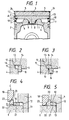
- Fig. 2 is an enlarged view of the portion represented by symbol A in Fig. 1 before a heat-insulating member is inserted;
- Fig. 3 is an enlarged view showing the state after insertion of Fig. 2;
- Fig. 4 is an enlarged view of the portion represented by symbol A in Fig. 1 and shows another example before insertion of the heat-insulating member;
- Fig. 5 is an enlarged view showing the state after insertion of Fig. 4; and
- Fig. 6 is a sectional view showing an example of the structure of a conventional heat-insulating piston.
- Fig. 1 shows the structure of the heat-insulating piston in accordance with an embodiment of the present invention. This heat-insulating piston comprises primarily a
piston skirt member 2, acylindrical member 4 coming partially into contact with thepiston skirt member 2, ahead base member 1 fixed to theskirt member 2, a heat-insulatingmember 3 disposed on thehead base member 1, athin film member 5 disposed on the heat-insulatingmember 3 and bonded around its periphery to thecylindrical member 4, and metallic heat-resistant members 10 disposed in the spaces between thecylindrical member 4 and thehead base member 1. - In this heat-insulating piston, the
piston skirt member 2 is made of a metallic material. Thecylindrical member 4 whose lower end surface is pushed to the upper end surface of the outer periphery of thepiston skirt member 2 and thehead base member 1 fixed to thepiston skirt member 2 while its peripheral portion is pushed and brought into contact with an innerperipheral step portion 12 of thecylindrical member 4 are made of a ceramic material such as silicon nitride (Si₃N₄), silicon carbide (SiC). Further, the heat-insulatingmember 3 disposed on the head base is made of a whisker fired material of a ceramic material such as silicon nitride (Si₃N₄), Silicon carbide (SiC). Thethin film member 5 which is disposed on the heat-insulatingmember 3 and whose peripheral portion is bonded to thecylindrical member 4 is made of a ceramic material such as silicon nitride (Si₃N₄) and silicon carbide (SiC). The metallic heat-resistant members 10 disposed between the innerperipheral step portion 12 of thecylindrical member 4 and theperipheral portion 13 of thehead base member 1 are made of a heat-resistant alloy such as a nickel alloy. - A combustion chamber is not formed in this
head base member 1 itself and the portion of thehead base member 1 on the combustion chamber side is shaped flat. Thehead base member 1 and thepiston skirt member 2 are fixed to each other by fitting thefitting boss portion 8 disposed at the center of thehead base member 1 into thefitting hole 11 formed at the center of thepiston skirt member 2 and disposing ametal ring 9 by metal flow into the groove portion defined between them. In this case, the innerperipheral step portion 12 is formed on thecylindrical member 4 constituting the upper portion of the slide surface of the piston, theperipheral portion 13 of thehead base member 1 is engaged with this innerperipheral step portion 12 and moreover, the upper end surface of the outer periphery of thecylindrical member 4 and the lower end surface of thepiston skirt member 2 are brought into pressure contact while interposing a seal member 7 between them. The heat-insulatingmember 3 is disposed in a cylindrical hole portion defined by thehead base portion 1 and thecylindrical member 4. A heat-insulatingair layer 6 is defined between the lower surface of thehead base member 1 and thepiston skirt member 2. - In this structure of the heat-insulating piston, the
thin film member 5 disposed on the outer surface of the heat-insulatingmember 3 is made of the same ceramic material as the heat-insulatingmember 3 such as silicon nitride (Si₃N₄), silicon carbide (SiC), and can be disposed on the heat-insulatingmember 3 by bonding it to the side of the heat-insulatingmember 3 exposed to the combustion gas, that is, on its surface on the combustion chamber side, by CVD (Chemical Vapor Deposition) or coating. Accordingly, since thisthin film member 5 provides the surface exposed to the combustion chamber and moreover, can be formed as thin as possible, the thermal capacity of the surface exposed to the combustion gas can be reduced and the structure can be made highly heat-resistant. This heat-insulatingmember 3 exhibits the heat-insulating function and at the same time, can function as a structural member which receive the pressure acting on the ceramicthin film member 5 at the time of explosion. In this structure of the heat-insulating piston, the compressive force due to explosion must be received uniformly by the heat-insulatingmember 3 and to this end, too, the upper surface of thehead base member 1 and thethin film member 5 are shaped in a flat form. - Particularly in order to insert the metallic heat-
resistant members 10 into the voids between the innerperipheral step portion 12 of thecylindrical member 4 and theperipheral portion 13 of thehead base member 1, they are softened and pushed into the voids defined by thegroove 15 formed in the innerperipheral step portion 12 of thecylindrical member 4 and thegroove 14 formed in theperipheral portion 13 of thehead base member 1 or pushed into the voids defined between the innerperipheral step portion 12 and theperipheral portion 13 of thehead base member 1, as will be described later, after thecylindrical member 4 and thethin film member 5 are mutually bonded at thejoint portion 24 of the peripheral portion but before thehead base member 1 and thepiston skirt member 2 are fixed to each other. When the metallic heat-resistant members 10 are inserted into the voids between the innerperipheral step portion 12 of thecylindrical member 4 and theperipheral portion 13 of thehead base member 1, the heat-insulatingmember 3 can be brought into contact with thethin film member 5 through thehead base member 1 and the occurrance of any gap between thethin film member 5 and the heat-insulatingmember 3 can be prevented. - In this structure of the heat-insulating piston, for example, the
groove 15 is formed in the innerperipheral step portion 12 of thecylindrical member 4 and thegroove 14 is formed in theperipheral portion 13 of thehead base member 1 in such a manner as to define the voids of the metallic heat-resistant members 10, that is, theiraccommodation portion 16, as shown in Fig. 2. The metallic heat-resistant members 10 can be disposed in thisaccommodation portion 16 in the following way. As shown in Fig.2, the metallic heat-resistant members 10 are first disposed at part of theaccommodation portion 16 and then the heat-resistant metal is locally heated by a radio frequency heater and softened. Then, it is pushed completely into theaccommodation portion 16 by use of ajig 17 as represented by arrow B in Fig. 3 and is thereafter hardened. - Alternatively, the metallic heat-
resistant members 10 can be disposed in the voids between the innerperipheral step portion 12 of thecylindrical member 4 and theperipheral portion 13 of thehead base member 1 in the following way. The metallic heat-resistant members 10 are fabricated to the thickness of the void between the innerperipheral step portion 12 of thecylindrical member 4 and theperipheral portion 13 of thehead base member 1 as shown in Fig. 4 and are placed on thelower surface 21 of thehead base member 1. Apush jig 22 having ataper surface 23 is put onto the side surface of the heat-resistant members 10. Then, anotherpush jig 18 having ataper surface 20 which comes into sliding contact with thetaper surface 23 of thepush jig 22 is pushed in the direction represented by arrow C, so that thepush jig 22 is moved in the direction represented by arrow D and can push the haat-resistant member 10 into the void between the innerperipheral step portion 12 of thecylindrical member 4 and theperipheral portion 13 of thehead base member 1.
Claims (14)
a piston skirt member having a peripheral upper end surface;
a ceramic cylindrical member having lower end surface thereof placed on said peripheral upper end surface of said piston skirt member to face the same;
said cylindrical member having a step portion extending inwardly in a radial direction, on the inner peripheral surface thereof;
a head base member fitted to said piston skirt member;
said head base member having the peripheral portion thereof kept in contact with said step portion of said cylindrical member;
a heat-insulating member disposed on the upper surface of said head base member; and
a flat, ceramic thin film member disposed on the upper surface of said heat-insulating member and having the peripheral portion thereof bonded to an upper end portion of said cylindrical member;
wherein metallic heat-resistant members are inserted into voids defined between said inner peripheral step portion of said cylindrical member and said peripheral portion of said head base member in order to prevent the occurrence of any gap between the lower surface of said thin film member and the upper surface of said heat-insulating member.
Applications Claiming Priority (2)
| Application Number | Priority Date | Filing Date | Title |
|---|---|---|---|
| JP1235639A JPH0668258B2 (en) | 1989-09-13 | 1989-09-13 | Structure of adiabatic piston |
| JP235639/89 | 1989-09-13 |
Publications (2)
| Publication Number | Publication Date |
|---|---|
| EP0417931A1 true EP0417931A1 (en) | 1991-03-20 |
| EP0417931B1 EP0417931B1 (en) | 1993-01-13 |
Family
ID=16989003
Family Applications (1)
| Application Number | Title | Priority Date | Filing Date |
|---|---|---|---|
| EP90309426A Expired - Lifetime EP0417931B1 (en) | 1989-09-13 | 1990-08-29 | Heat-insulating piston |
Country Status (4)
| Country | Link |
|---|---|
| US (1) | US5018489A (en) |
| EP (1) | EP0417931B1 (en) |
| JP (1) | JPH0668258B2 (en) |
| DE (2) | DE69000765T2 (en) |
Families Citing this family (2)
| Publication number | Priority date | Publication date | Assignee | Title |
|---|---|---|---|---|
| CN201288658Y (en) * | 2008-11-20 | 2009-08-12 | 浙江荣鹏气动工具有限公司 | Wear-resistant plunger rod |
| US20130104846A1 (en) * | 2011-08-12 | 2013-05-02 | Mcalister Technologies, Llc | Combustion chamber inserts and associated methods of use and manufacture |
Citations (3)
| Publication number | Priority date | Publication date | Assignee | Title |
|---|---|---|---|---|
| US4592268A (en) * | 1983-12-27 | 1986-06-03 | Ford Motor Company | Method of making and apparatus for composite pistons |
| EP0321159A2 (en) * | 1987-12-14 | 1989-06-21 | Isuzu Motors Limited | Heat insulating engine |
| US4848291A (en) * | 1987-05-30 | 1989-07-18 | Isuzu Motors Limited | Heat-insulating piston structure |
Family Cites Families (6)
| Publication number | Priority date | Publication date | Assignee | Title |
|---|---|---|---|---|
| US4552057A (en) * | 1983-12-30 | 1985-11-12 | Gte Products Corporation | Thermally insulated piston |
| JPS60190651A (en) * | 1984-03-12 | 1985-09-28 | Ngk Insulators Ltd | Engine piston and manufacturing method thereof |
| BR8500556A (en) * | 1985-02-07 | 1986-09-09 | Metal Leve S/A. Industria E Comercio | PUMP AND PUMP MANUFACTURING PROCESS FOR INTERNAL COMBUSTION ENGINES |
| GB8622538D0 (en) * | 1986-09-18 | 1986-10-22 | Ae Plc | Pistons |
| JPS63302164A (en) * | 1987-05-30 | 1988-12-09 | Isuzu Motors Ltd | Construction of adiabatic piston |
| JP2629208B2 (en) * | 1987-10-22 | 1997-07-09 | いすゞ自動車株式会社 | Ceramic member joining method |
-
1989
- 1989-09-13 JP JP1235639A patent/JPH0668258B2/en not_active Expired - Lifetime
-
1990
- 1990-08-23 US US07/571,359 patent/US5018489A/en not_active Expired - Fee Related
- 1990-08-29 EP EP90309426A patent/EP0417931B1/en not_active Expired - Lifetime
- 1990-08-29 DE DE9090309426T patent/DE69000765T2/en not_active Expired - Fee Related
- 1990-08-29 DE DE199090309426T patent/DE417931T1/en active Pending
Patent Citations (3)
| Publication number | Priority date | Publication date | Assignee | Title |
|---|---|---|---|---|
| US4592268A (en) * | 1983-12-27 | 1986-06-03 | Ford Motor Company | Method of making and apparatus for composite pistons |
| US4848291A (en) * | 1987-05-30 | 1989-07-18 | Isuzu Motors Limited | Heat-insulating piston structure |
| EP0321159A2 (en) * | 1987-12-14 | 1989-06-21 | Isuzu Motors Limited | Heat insulating engine |
Non-Patent Citations (1)
| Title |
|---|
| PATENT ABSTRACTS OF JAPAN, unexamined applications, M field, vol. 13, no. 133, April 4, 1989 THE PATENT OFFICE JAPANESE GOVERNMENT page 132 M 809 * JP - A - 63 -302 125 ( ISUZU MOTORS LTD ) * * |
Also Published As
| Publication number | Publication date |
|---|---|
| JPH03100356A (en) | 1991-04-25 |
| US5018489A (en) | 1991-05-28 |
| DE69000765T2 (en) | 1993-05-27 |
| JPH0668258B2 (en) | 1994-08-31 |
| EP0417931B1 (en) | 1993-01-13 |
| DE417931T1 (en) | 1991-10-17 |
| DE69000765D1 (en) | 1993-02-25 |
Similar Documents
| Publication | Publication Date | Title |
|---|---|---|
| US4942999A (en) | Metal-ceramic joined composite bodies and joining process therefor | |
| US6758386B2 (en) | Method of joining ceramic matrix composites and metals | |
| EP0294091B1 (en) | Heat insulating piston structure | |
| EP0530854B1 (en) | Metal-ceramic composite bodies | |
| EP1695949A1 (en) | Joined body and manufacturing method for the same | |
| US20040194941A1 (en) | Active cooling panel of thermostructural composite material and method for its manufacture | |
| US5282411A (en) | Heat-insulating piston with middle section of less dense but same material | |
| EP0155159A2 (en) | An internal combustion engine piston and a method of producing the same | |
| US5018489A (en) | Heat-insulating piston | |
| EP0287236B1 (en) | Heat-insulating engine structure and method of manufacturing the same | |
| EP0472171B1 (en) | Ceramic rotor and metal shaft assembly | |
| EP0211347B1 (en) | Rotary shaft assembly and method for joining a shaft portion of ceramics construction with a boss portion of metal construction | |
| EP0412660B1 (en) | Heat-insulating piston | |
| US5014604A (en) | Piston for internal combustion engine | |
| JPH1053470A (en) | Joined body of ceramic and its production | |
| JP2811840B2 (en) | Manufacturing method of ceramic parts such as pistons | |
| JP2560422B2 (en) | Structure of adiabatic piston | |
| JP2964102B2 (en) | Adiabatic piston and its manufacturing method | |
| JP3506876B2 (en) | Engine tappet | |
| JP2629208B2 (en) | Ceramic member joining method | |
| JPH1171186A (en) | Bound structure of ceramic to metal and its binding | |
| JP3109156B2 (en) | Insulated piston | |
| JPH0674770B2 (en) | Structure of adiabatic piston | |
| JPS61219765A (en) | Composite body of ceramic and metal | |
| JPS5988379A (en) | Ceramic-metal composite body |
Legal Events
| Date | Code | Title | Description |
|---|---|---|---|
| PUAI | Public reference made under article 153(3) epc to a published international application that has entered the european phase |
Free format text: ORIGINAL CODE: 0009012 |
|
| AK | Designated contracting states |
Kind code of ref document: A1 Designated state(s): DE GB |
|
| 17P | Request for examination filed |
Effective date: 19910426 |
|
| 17Q | First examination report despatched |
Effective date: 19910903 |
|
| DET | De: translation of patent claims | ||
| GRAA | (expected) grant |
Free format text: ORIGINAL CODE: 0009210 |
|
| AK | Designated contracting states |
Kind code of ref document: B1 Designated state(s): DE GB |
|
| REF | Corresponds to: |
Ref document number: 69000765 Country of ref document: DE Date of ref document: 19930225 |
|
| PLBE | No opposition filed within time limit |
Free format text: ORIGINAL CODE: 0009261 |
|
| STAA | Information on the status of an ep patent application or granted ep patent |
Free format text: STATUS: NO OPPOSITION FILED WITHIN TIME LIMIT |
|
| 26N | No opposition filed | ||
| PGFP | Annual fee paid to national office [announced via postgrant information from national office to epo] |
Ref country code: GB Payment date: 19950816 Year of fee payment: 6 |
|
| PGFP | Annual fee paid to national office [announced via postgrant information from national office to epo] |
Ref country code: DE Payment date: 19950926 Year of fee payment: 6 |
|
| PG25 | Lapsed in a contracting state [announced via postgrant information from national office to epo] |
Ref country code: GB Effective date: 19960829 |
|
| GBPC | Gb: european patent ceased through non-payment of renewal fee |
Effective date: 19960829 |
|
| PG25 | Lapsed in a contracting state [announced via postgrant information from national office to epo] |
Ref country code: DE Effective date: 19970501 |