EP0422436A2 - Plastic bottle with reinforced concave bottom - Google Patents
Plastic bottle with reinforced concave bottom Download PDFInfo
- Publication number
- EP0422436A2 EP0422436A2 EP90118285A EP90118285A EP0422436A2 EP 0422436 A2 EP0422436 A2 EP 0422436A2 EP 90118285 A EP90118285 A EP 90118285A EP 90118285 A EP90118285 A EP 90118285A EP 0422436 A2 EP0422436 A2 EP 0422436A2
- Authority
- EP
- European Patent Office
- Prior art keywords
- bottle
- concave
- hollow ribs
- concave portion
- bottom rim
- Prior art date
- Legal status (The legal status is an assumption and is not a legal conclusion. Google has not performed a legal analysis and makes no representation as to the accuracy of the status listed.)
- Granted
Links
- 239000004033 plastic Substances 0.000 title description 18
- 239000007787 solid Substances 0.000 claims abstract description 28
- 238000000071 blow moulding Methods 0.000 claims description 7
- 210000002445 nipple Anatomy 0.000 claims description 4
- 238000006073 displacement reaction Methods 0.000 claims 2
- 239000002991 molded plastic Substances 0.000 abstract description 2
- 239000002990 reinforced plastic Substances 0.000 abstract 1
- 239000000463 material Substances 0.000 description 13
- 230000002787 reinforcement Effects 0.000 description 6
- 238000001125 extrusion Methods 0.000 description 5
- 238000007664 blowing Methods 0.000 description 3
- 239000010410 layer Substances 0.000 description 3
- 239000004417 polycarbonate Substances 0.000 description 3
- 229920000515 polycarbonate Polymers 0.000 description 3
- 229920006020 amorphous polyamide Polymers 0.000 description 2
- 230000015572 biosynthetic process Effects 0.000 description 1
- 235000014171 carbonated beverage Nutrition 0.000 description 1
- 230000002860 competitive effect Effects 0.000 description 1
- 238000004519 manufacturing process Methods 0.000 description 1
- 230000004048 modification Effects 0.000 description 1
- 238000012986 modification Methods 0.000 description 1
- 230000002093 peripheral effect Effects 0.000 description 1
- 239000002243 precursor Substances 0.000 description 1
- -1 regrind Polymers 0.000 description 1
- 239000011435 rock Substances 0.000 description 1
- 239000002356 single layer Substances 0.000 description 1
Images

Classifications
-
- B—PERFORMING OPERATIONS; TRANSPORTING
- B65—CONVEYING; PACKING; STORING; HANDLING THIN OR FILAMENTARY MATERIAL
- B65D—CONTAINERS FOR STORAGE OR TRANSPORT OF ARTICLES OR MATERIALS, e.g. BAGS, BARRELS, BOTTLES, BOXES, CANS, CARTONS, CRATES, DRUMS, JARS, TANKS, HOPPERS, FORWARDING CONTAINERS; ACCESSORIES, CLOSURES, OR FITTINGS THEREFOR; PACKAGING ELEMENTS; PACKAGES
- B65D1/00—Containers having bodies formed in one piece, e.g. by casting metallic material, by moulding plastics, by blowing vitreous material, by throwing ceramic material, by moulding pulped fibrous material, by deep-drawing operations performed on sheet material
- B65D1/02—Bottles or similar containers with necks or like restricted apertures, designed for pouring contents
- B65D1/0223—Bottles or similar containers with necks or like restricted apertures, designed for pouring contents characterised by shape
- B65D1/0261—Bottom construction
- B65D1/0276—Bottom construction having a continuous contact surface, e.g. Champagne-type bottom
-
- B—PERFORMING OPERATIONS; TRANSPORTING
- B29—WORKING OF PLASTICS; WORKING OF SUBSTANCES IN A PLASTIC STATE IN GENERAL
- B29C—SHAPING OR JOINING OF PLASTICS; SHAPING OF MATERIAL IN A PLASTIC STATE, NOT OTHERWISE PROVIDED FOR; AFTER-TREATMENT OF THE SHAPED PRODUCTS, e.g. REPAIRING
- B29C49/00—Blow-moulding, i.e. blowing a preform or parison to a desired shape within a mould; Apparatus therefor
- B29C49/22—Blow-moulding, i.e. blowing a preform or parison to a desired shape within a mould; Apparatus therefor using multilayered preforms or parisons
-
- B—PERFORMING OPERATIONS; TRANSPORTING
- B29—WORKING OF PLASTICS; WORKING OF SUBSTANCES IN A PLASTIC STATE IN GENERAL
- B29C—SHAPING OR JOINING OF PLASTICS; SHAPING OF MATERIAL IN A PLASTIC STATE, NOT OTHERWISE PROVIDED FOR; AFTER-TREATMENT OF THE SHAPED PRODUCTS, e.g. REPAIRING
- B29C49/00—Blow-moulding, i.e. blowing a preform or parison to a desired shape within a mould; Apparatus therefor
- B29C49/02—Combined blow-moulding and manufacture of the preform or the parison
- B29C49/04—Extrusion blow-moulding
-
- B—PERFORMING OPERATIONS; TRANSPORTING
- B29—WORKING OF PLASTICS; WORKING OF SUBSTANCES IN A PLASTIC STATE IN GENERAL
- B29K—INDEXING SCHEME ASSOCIATED WITH SUBCLASSES B29B, B29C OR B29D, RELATING TO MOULDING MATERIALS OR TO MATERIALS FOR MOULDS, REINFORCEMENTS, FILLERS OR PREFORMED PARTS, e.g. INSERTS
- B29K2069/00—Use of PC, i.e. polycarbonates or derivatives thereof, as moulding material
-
- B—PERFORMING OPERATIONS; TRANSPORTING
- B29—WORKING OF PLASTICS; WORKING OF SUBSTANCES IN A PLASTIC STATE IN GENERAL
- B29K—INDEXING SCHEME ASSOCIATED WITH SUBCLASSES B29B, B29C OR B29D, RELATING TO MOULDING MATERIALS OR TO MATERIALS FOR MOULDS, REINFORCEMENTS, FILLERS OR PREFORMED PARTS, e.g. INSERTS
- B29K2077/00—Use of PA, i.e. polyamides, e.g. polyesteramides or derivatives thereof, as moulding material
- B29K2077/10—Aromatic polyamides [polyaramides] or derivatives thereof
Definitions
- the invention relates to plastic bottles formed with concave bottoms which are reinforced to resist bulging from the pressure of contents of the bottles.
- Plastic bottles are formed with concave bottoms in order to form an outer bottom rim by which the bottles can stand upright on a shelf.
- the plastic material in the bottles is made as thin as possible in order to minimize the quantity of plastic material so that the bottles can be produced at a cost which is competitive with other commercially produced bottles.
- Flat bottoms made of such thin plastic materials would bulge from the pressure of carbonated beverages and render bottles with such bottoms unstable when placed upright on a shelf causing the bottles to rock or fall over.
- Bottoms with concave center portions offer an improvement in shelf stability of the bottles, but the competition to reduce cost by using less material in the bottle has lead to many different types of reinforcements for concave bottoms to avoid bulging of the thinner concave bottoms.
- U.S. Patent No. 4,502,607 shows a depending solid rib formed along the mold parting line at the pinched off end of a preform.
- This rib offers substantial support for the concave portion of the bottom to prevent bulging of the concave portion.
- bottles formed with such depending solid ribs are subject to standing instability due to bulging from internal bottle pressures in bottom rim portions which are disposed on opposite sides of the solid ribs.
- U.S. Patent No. 4,108,324 which has eight radially spaced hollow convex ribs extending from the concave portion to the rim portion of the bottom. While these hollow convex ribs result in increased resistance to bulging compared to a non-reinforced concave bottom, they do not produce the degree of bulge resistance that a solid rib formed at the pinch off seam can produce.
- the invention is summarized in a reinforced concave bottom for a plastic bottle having the combination of a depending solid rib extending across the concave portion and being joined at opposite ends to opposite portions of the rim portion of the bottom, and a pair of depending hollow ribs formed in the concave portion on respective opposite sides of the solid rib, the hollow ribs extending radially in periphery of the concave portion and being joined with the bottom rim portion intermediate the junctions of the solid rib with the bottom rim portion.
- one embodiment of the invention is a plastic bottle 20 having a bottom with a concave portion 24 and a rim portion 26 which surrounds and extends downward from the concave portion.
- Reinforcements for the bottom include a solid depending rib 30 and two hollow depending ribs 32 and 34.
- the solid rib 30 is formed by a sealed seam at the pinch off juncture along the mold seam line 36 of the bottle and extends across the concave portion 24 with its opposite ends 40 and 42 being joined with the rim portion 26.
- the hollow ribs 32 and 34 are formed by downwardly deflected portions of the concave portion 24 on opposite sides of the solid rib 30, and extend radially over a peripheral portion of the concavity 24 to the bottom rim 26 where the ribs 32 and 34 join with the inside wall 44 of the bottom rim intermediate to the junctions of the bottom rim with the solid rib ends 40 and 42.
- the height of the wall 44 is substantially reduced as can be seen be the dimension 50 in Fig. 3. This height reduction substantially reduces the amount that the material must stretch in this region to result in increased thickness and resistance against bulging from internal bottle pressure.
- the hollow ribs 32 and 34 are located ninety degrees or perpendicular to the solid rib 30.
- the ribs 30, 32 and 34 have depths selected to give substantial reinforcement while avoiding extending below the bottom rim 26 under conditions of normal internal bottle pressures.
- the bottle 20 has a tubular wall 60 with spaced raised annular bands 62 and 64.
- the outer surfaces of the bands can be roughened or knurled to enable more sure gripping of the bottle.
- the upper portion of the bottle is defined by a curved tapered extension 66 of the wall 60 with a threaded nipple 68 formed on top. Pinch off junctions 70 and 72 are formed in the upper portion of the bottle.
- the bottle is formed by conventional blow molding, for example, as shown in Figs. 5, 6 and 7.
- a tubular segment of plastic material 76 is extruded by extrusion apparatus indicated generally at 80.
- An outer ring member 81 of the extrusion apparatus is moved up and down in a conventional manner to vary the thickness of the wall of the tubular segment 76 in accordance with conventional practice.
- the bottom portion of the tube 76 will have a thicker wall than the upper portion.
- a bottle preform 82 is made by closing mold halves 84 and 86, which have respective movable inserts 87 and 89, on the hot tubular segment 76 and severing the segment from the extruder 80 with a hot knife (not shown).
- a portion of the bottom end of the tube 76 is pinched off by die pinch off members 90 and 92, and upper side portions of the tube 76 are similarly pinched off by die members (only upper pinch off members 94 and 96 are shown in Fig. 6).
- the die halves 84 and 86 have respective recesses 100 and 102 which squeeze portions of opposite sides of the tube 76 together to form a seam which is the precursor of the solid rib 30.
- the closed mold halves with the preform 82 therein are moved from the extrusion station, Fig. 5, and to the blowing station, Fig. 6, where a hollow forming die 104 is inserted into the open upper end of the hot preform 82 to form the threaded nipple 68. Gas or air is forced into the hot preform 82 through the hollow forming die 104 to mold the bottle into its final shape.
- Bottom portions 106 and 108 of the die halves 84 and 86 form the concave portion 24 of the bottle while annular groove sections 107 and 109 behind the respective portions 106 and 108 form the bottom rim 26 of the bottle.
- Grooves 110 and 112 in the respective die portions 106 and 108 form the hollow ribs 32 and 34 of the bottle.
- the hot plastic preform readily stretches or flows to the shape of the cavity formed by the die halves.
- the largest amount of stretching and plastic flow occurs in the grooves 107 and 109 forming the bottom rim 26.
- the area of the seam, i.e. areas 40 and 42 where the solid rib 30 joins the bottom rim is thicker and offers more resistance to stretching and plastic flow.
- the grooves 110 and 112 effectively reduce the depth of the bottom rim forming grooves 107 and 109 relative to the depth of the rim formed at locations spaced from the grooves 110 and 112 to reduce the amount of stretching and plastic flow in the regions 46 and 48.
- the hollow ribs 32 and 34 result in thicker and stronger wall portions in the bottom rim areas 46 and 48 compared to a bottle formed from similar plastic tube thicknesses with a solid bottom rib and no hollow ribs. This reduces the tendency in bottles formed with a solid bottom rib to bulge in bottom rim regions located ninety degrees from the solid rib to avoid instability or rocking of the bottle in an upright position.
- the hollow ribs 32 and 34 in combination with the solid rib 30 provide greatly improved reinforcement for the concave bottom portion to enable more economical manufacture of blow molded plastic bottles.
- the bottle After blow molding, the bottle is removed from the mold and the excess preform material above the nipple 68 and below the pinch off inserts 100 and 102 is trimmed to complete formation of the bottle.
- the tube 76 can be a single layer of a suitable plastic material or can be multiple layers of different plastic materials.
- One particularly suitable extrusion is formed by outer and inner layers of polycarbonate with an intermediate layer of amorphous polyamide; examples of materials forming such multilayer containers are disclosed in U.S. Patent Application Serial No. 07/298,390 filed January 18, 1989, and which is incorporated herein by reference.
- the extrusion 76 is formed from five coaxially extruded layers, from outside to inside -- polycarbonate, regrind, amorphous polyamide, regrind and polycarbonate. Regrind includes the trimmed excess preform material.
Abstract
Description
- The invention relates to plastic bottles formed with concave bottoms which are reinforced to resist bulging from the pressure of contents of the bottles.
- Plastic bottles are formed with concave bottoms in order to form an outer bottom rim by which the bottles can stand upright on a shelf. The plastic material in the bottles is made as thin as possible in order to minimize the quantity of plastic material so that the bottles can be produced at a cost which is competitive with other commercially produced bottles. Flat bottoms made of such thin plastic materials would bulge from the pressure of carbonated beverages and render bottles with such bottoms unstable when placed upright on a shelf causing the bottles to rock or fall over. Bottoms with concave center portions offer an improvement in shelf stability of the bottles, but the competition to reduce cost by using less material in the bottle has lead to many different types of reinforcements for concave bottoms to avoid bulging of the thinner concave bottoms.
- One example of a prior art reinforced concave bottom is illustrated in U.S. Patent No. 4,502,607 which shows a depending solid rib formed along the mold parting line at the pinched off end of a preform. This rib offers substantial support for the concave portion of the bottom to prevent bulging of the concave portion. However, bottles formed with such depending solid ribs are subject to standing instability due to bulging from internal bottle pressures in bottom rim portions which are disposed on opposite sides of the solid ribs.
- Another example of prior art bottom reinforcement is shown in U.S. Patent No. 4,108,324 which has eight radially spaced hollow convex ribs extending from the concave portion to the rim portion of the bottom. While these hollow convex ribs result in increased resistance to bulging compared to a non-reinforced concave bottom, they do not produce the degree of bulge resistance that a solid rib formed at the pinch off seam can produce.
- The invention is summarized in a reinforced concave bottom for a plastic bottle having the combination of a depending solid rib extending across the concave portion and being joined at opposite ends to opposite portions of the rim portion of the bottom, and a pair of depending hollow ribs formed in the concave portion on respective opposite sides of the solid rib, the hollow ribs extending radially in periphery of the concave portion and being joined with the bottom rim portion intermediate the junctions of the solid rib with the bottom rim portion.
- It has been found that instability in a concave bottom of a plastic bottle with a depending solid rib formed at the pinch off seam can be overcome by forming hollow depending ribs on opposite sides of the solid rib and extending to the bottom rim portion. The hollow ribs joining the bottom rim reduce the amount of stretch during blow molding in the plastic material in the bottom rim intermediate the junctions with the solid rib. This results in increased thickness at such intermediate portions which in turn enables reduced material usage and substantial cost savings.
- Other objects, advantages and features of the invention will be apparent from the following description of the preferred embodiment taken in conjunction with the accompanying drawings.
-
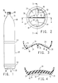
- Fig. 1 is an elevation view of a bottle with concave bottom reinforcements shown diagrammatically by hidden lines.
- Fig. 2 is a bottom view of the bottle of Fig. 1.
- Fig. 3 is a section view of a broken away bottom portion of the bottle taken at line 3-3 of Fig. 2.
- Fig. 4 is a section view of a broken away bottom portion of the bottle taken at line 4-4 of Fig. 2.
- Fig. 5 is a section view of a broken away portion of a blow molding apparatus for forming the bottle of Fig. 1.
- Fig. 6 is a section view of a mold half taken at line 6-6 in Fig. 5 but at a later time after the preform and mold have been moved to a blowing station.
- Fig. 7 is a section view taken at line 7-7 in Fig. 6.
- As shown in Figs. 1, 2, 3 and 4, one embodiment of the invention is a
plastic bottle 20 having a bottom with aconcave portion 24 and arim portion 26 which surrounds and extends downward from the concave portion. Reinforcements for the bottom include a solid dependingrib 30 and two hollow dependingribs solid rib 30 is formed by a sealed seam at the pinch off juncture along themold seam line 36 of the bottle and extends across theconcave portion 24 with itsopposite ends rim portion 26. Thehollow ribs concave portion 24 on opposite sides of thesolid rib 30, and extend radially over a peripheral portion of theconcavity 24 to thebottom rim 26 where theribs inside wall 44 of the bottom rim intermediate to the junctions of the bottom rim with thesolid rib ends regions hollow ribs inner wall 44 of the bottom rim, the height of thewall 44 is substantially reduced as can be seen be thedimension 50 in Fig. 3. This height reduction substantially reduces the amount that the material must stretch in this region to result in increased thickness and resistance against bulging from internal bottle pressure. In the illustrated example of the preferred embodiment, thehollow ribs solid rib 30. Theribs bottom rim 26 under conditions of normal internal bottle pressures. - The
bottle 20 has atubular wall 60 with spaced raisedannular bands tapered extension 66 of thewall 60 with a threadednipple 68 formed on top. Pinch offjunctions - The bottle is formed by conventional blow molding, for example, as shown in Figs. 5, 6 and 7. A tubular segment of
plastic material 76 is extruded by extrusion apparatus indicated generally at 80. Anouter ring member 81 of the extrusion apparatus is moved up and down in a conventional manner to vary the thickness of the wall of thetubular segment 76 in accordance with conventional practice. Generally the bottom portion of thetube 76 will have a thicker wall than the upper portion. - A
bottle preform 82 is made by closingmold halves movable inserts tubular segment 76 and severing the segment from theextruder 80 with a hot knife (not shown). During closing of the mold halves, a portion of the bottom end of thetube 76 is pinched off by die pinch offmembers tube 76 are similarly pinched off by die members (only upper pinch offmembers members halves respective recesses tube 76 together to form a seam which is the precursor of thesolid rib 30. The closed mold halves with thepreform 82 therein are moved from the extrusion station, Fig. 5, and to the blowing station, Fig. 6, where ahollow forming die 104 is inserted into the open upper end of thehot preform 82 to form the threadednipple 68. Gas or air is forced into thehot preform 82 through thehollow forming die 104 to mold the bottle into its final shape.Bottom portions die halves concave portion 24 of the bottle whileannular groove sections respective portions bottom rim 26 of the bottle.Grooves die portions hollow ribs - During the blowing of the preform to the final shape, the hot plastic preform readily stretches or flows to the shape of the cavity formed by the die halves. The largest amount of stretching and plastic flow occurs in the
grooves bottom rim 26. The area of the seam, i.e.areas solid rib 30 joins the bottom rim is thicker and offers more resistance to stretching and plastic flow. Thegrooves rim forming grooves grooves regions hollow ribs bottom rim areas hollow ribs solid rib 30 provide greatly improved reinforcement for the concave bottom portion to enable more economical manufacture of blow molded plastic bottles. - After blow molding, the bottle is removed from the mold and the excess preform material above the
nipple 68 and below the pinch offinserts - The
tube 76 can be a single layer of a suitable plastic material or can be multiple layers of different plastic materials. One particularly suitable extrusion is formed by outer and inner layers of polycarbonate with an intermediate layer of amorphous polyamide; examples of materials forming such multilayer containers are disclosed in U.S. Patent Application Serial No. 07/298,390 filed January 18, 1989, and which is incorporated herein by reference. In one example of a bottle made in accordance with the invention, theextrusion 76 is formed from five coaxially extruded layers, from outside to inside -- polycarbonate, regrind, amorphous polyamide, regrind and polycarbonate. Regrind includes the trimmed excess preform material. - Since many variations, modifications and changes in detail can be made to the above disclosed embodiment without departing from the scope and spirit of the invention, it is intended that the above disclosure and accompanying drawings be interpreted as illustrative and not in a limiting sense.
Claims (6)
a tubular wall having an upper portion and a lower portion,
a nipple formed on the upper portion to provide for flow of contents into and out of the bottle;
a bottom including a center concave portion and a bottom rim portion surrounding and extending down from the concave portion;
a depending solid rib extending across the concave portion and joined at opposite ends of the solid rib to opposite sides of the bottom rim portion; and
a pair of depending hollow ribs formed in the concave portion on respective opposite sides of the solid rib;
said hollow ribs extending radially in the concave portion and being joined to the bottom rim.
Applications Claiming Priority (2)
| Application Number | Priority Date | Filing Date | Title |
|---|---|---|---|
| US420884 | 1989-10-13 | ||
| US07/420,884 US4989738A (en) | 1989-10-13 | 1989-10-13 | Plastic bottle with reinforced concave bottom |
Publications (3)
| Publication Number | Publication Date |
|---|---|
| EP0422436A2 true EP0422436A2 (en) | 1991-04-17 |
| EP0422436A3 EP0422436A3 (en) | 1992-02-26 |
| EP0422436B1 EP0422436B1 (en) | 1994-06-15 |
Family
ID=23668233
Family Applications (1)
| Application Number | Title | Priority Date | Filing Date |
|---|---|---|---|
| EP90118285A Expired - Lifetime EP0422436B1 (en) | 1989-10-13 | 1990-09-24 | Plastic bottle with reinforced concave bottom |
Country Status (4)
| Country | Link |
|---|---|
| US (1) | US4989738A (en) |
| EP (1) | EP0422436B1 (en) |
| JP (1) | JPH03187829A (en) |
| DE (1) | DE69009926T2 (en) |
Cited By (2)
| Publication number | Priority date | Publication date | Assignee | Title |
|---|---|---|---|---|
| EP1705124A1 (en) * | 2005-03-15 | 2006-09-27 | TECHNE TECHNIPACK ENGINEERING ITALIA S.p.A. | Bottle made of plastic material with reinforced bottom |
| GB2510796A (en) * | 2012-09-24 | 2014-08-20 | Nampak Plastics Europe Ltd | Plastics container |
Families Citing this family (17)
| Publication number | Priority date | Publication date | Assignee | Title |
|---|---|---|---|---|
| JP3019095U (en) * | 1995-06-07 | 1995-12-05 | 石川工業株式会社 | Shampoo container with discharge mechanism |
| KR100309183B1 (en) * | 1998-12-18 | 2002-11-13 | 에스케이케미칼주식회사 | Carbonated beverage bottle with bursting structure and its manufacturing apparatus |
| US20020121139A1 (en) * | 2001-03-02 | 2002-09-05 | Purpura Paul E. | Adapter for holding a sample container to facilitate sensing of liquid level in the sample container |
| US6569376B2 (en) * | 2001-04-13 | 2003-05-27 | Schmalbach-Lubeca Ag | Process for improving material thickness distribution within a molded bottle and bottle therefrom |
| US6769561B2 (en) * | 2001-12-21 | 2004-08-03 | Ball Corporation | Plastic bottle with champagne base |
| US7000793B2 (en) * | 2003-02-24 | 2006-02-21 | Graham Packaging Co., L.P. | Hot-fill container base structure |
| US20080197140A1 (en) * | 2007-02-16 | 2008-08-21 | John Cheslock | Mug with removable spiked bottom panel |
| US20100012617A1 (en) * | 2008-07-16 | 2010-01-21 | Ulibarri Scott M | Plastic bottle with superior top load strength |
| US8893908B2 (en) | 2012-08-03 | 2014-11-25 | Eastman Chemical Company | Extrusion blow molding system having enhanced pinch geometry |
| USD767401S1 (en) | 2014-05-29 | 2016-09-27 | Graham Packaging Company, L.P. | Container |
| JP6385259B2 (en) * | 2014-11-28 | 2018-09-05 | 株式会社吉野工業所 | Double container |
| US10252834B2 (en) * | 2014-12-22 | 2019-04-09 | Graham Packaging Company, L.P. | Rigid structured polymer container |
| USD793859S1 (en) | 2015-12-17 | 2017-08-08 | Graham Packaging Company, L.P. | Container |
| USD794445S1 (en) | 2015-12-17 | 2017-08-15 | Graham Packaging Company, L.P. | Container |
| JP6653967B2 (en) * | 2016-05-27 | 2020-02-26 | 株式会社吉野工業所 | Humidity control container |
| JP6925740B2 (en) * | 2017-10-27 | 2021-08-25 | 株式会社吉野工業所 | Laminated container |
| USD918045S1 (en) | 2019-03-05 | 2021-05-04 | Graham Packaging Company, L.P. | Container |
Citations (5)
| Publication number | Priority date | Publication date | Assignee | Title |
|---|---|---|---|---|
| US3403804A (en) * | 1965-12-10 | 1968-10-01 | L M P Lavorazione Materie Plas | Blown bottle of flexible plastics |
| AU6812974A (en) * | 1973-05-10 | 1975-10-23 | Advance Ind Ltd | Blow moulded plastic containers |
| US4108324A (en) * | 1977-05-23 | 1978-08-22 | The Continental Group, Inc. | Ribbed bottom structure for plastic container |
| US4502607A (en) * | 1983-06-21 | 1985-03-05 | Continental Plastic Containers, Inc. | Bulge resistant bottle bottom |
| US4759454A (en) * | 1986-12-29 | 1988-07-26 | Owens-Illinois Plastic Products Inc. | Hollow plastic bottle with wrap-around label |
Family Cites Families (28)
| Publication number | Priority date | Publication date | Assignee | Title |
|---|---|---|---|---|
| CA617278A (en) * | 1961-03-28 | T. Wallace Robert | Molded articles having molding seams or the like formed on the base thereof | |
| US3029963A (en) * | 1958-01-22 | 1962-04-17 | Evers Heinz | Bottle |
| US3598270A (en) * | 1969-04-14 | 1971-08-10 | Continental Can Co | Bottom end structure for plastic containers |
| FR2132543B1 (en) * | 1971-04-08 | 1974-10-31 | Saint Gobain Pont A Mousson | |
| US3718229A (en) * | 1971-10-26 | 1973-02-27 | Du Pont | Noneverting bottom for thermoplastic bottles |
| BE790814A (en) * | 1971-11-01 | 1973-04-30 | Du Pont | NON-TURNING BOTTOM FOR THERMOPLASTIC BOTTLE |
| US3757978A (en) * | 1971-12-22 | 1973-09-11 | Phillips Petroleum Co | Biaxially oriented blow molded article with ribs parallel to seam |
| US3843005A (en) * | 1972-02-11 | 1974-10-22 | Owens Illinois Inc | Blown plastic container |
| US3871541A (en) * | 1973-02-26 | 1975-03-18 | Continental Can Co | Bottom structure for plastic containers |
| US3881621A (en) * | 1973-07-02 | 1975-05-06 | Continental Can Co | Plastic container with noneverting bottom |
| US3949033A (en) * | 1973-11-02 | 1976-04-06 | Owens-Illinois, Inc. | Method of making a blown plastic container having a multi-axially stretch oriented concave bottom |
| US3956441A (en) * | 1974-09-16 | 1976-05-11 | Owens-Illinois, Inc. | Method of making a blown bottle having a ribbed interior surface |
| US4024975A (en) * | 1974-09-16 | 1977-05-24 | Owens-Illinois, Inc. | Reinforced bottle |
| CH607571A5 (en) * | 1977-02-01 | 1978-08-31 | Orbisphere Corp | |
| US4170622A (en) * | 1977-05-26 | 1979-10-09 | Owens-Illinois, Inc. | Method of making a blown hollow article having a ribbed interior surface |
| US4151249A (en) * | 1978-01-05 | 1979-04-24 | Owens-Illinois, Inc. | Method of making a blown bottle with internal ribs |
| US4335821A (en) * | 1979-07-03 | 1982-06-22 | The Continental Group, Inc. | Blow molded plastic material bottle bottom |
| US4247012A (en) * | 1979-08-13 | 1981-01-27 | Sewell Plastics, Inc. | Bottom structure for plastic container for pressurized fluids |
| US4525401A (en) * | 1979-11-30 | 1985-06-25 | The Continental Group, Inc. | Plastic container with internal rib reinforced bottom |
| US4334627A (en) * | 1979-11-27 | 1982-06-15 | The Continental Group, Inc. | Blow molded plastic bottle |
| US4261948A (en) * | 1979-11-27 | 1981-04-14 | The Continental Group, Inc. | Method of increasing the wall thickness of a bottom structure of a blown plastic material container |
| US4342398A (en) * | 1980-10-16 | 1982-08-03 | Owens-Illinois, Inc. | Self-supporting plastic container for liquids |
| US4513037A (en) * | 1983-12-29 | 1985-04-23 | General Electric Company | Multilayered hollow polycarbonate containers |
| US4605576B1 (en) * | 1984-10-22 | 1999-08-24 | Owens Brockway Plastic Prod | Multilayer plastic article |
| US4610366A (en) * | 1985-11-25 | 1986-09-09 | Owens-Illinois, Inc. | Round juice bottle formed from a flexible material |
| US4755404A (en) * | 1986-05-30 | 1988-07-05 | Continental Pet Technologies, Inc. | Refillable polyester beverage bottle and preform for forming same |
| USH469H (en) * | 1986-11-04 | 1988-05-03 | E. I. Du Pont De Nemours And Company | Clear plastic container with good gas and water vapor barrier properties |
| US4800129A (en) * | 1987-03-26 | 1989-01-24 | E. I. Du Pont De Nemours And Company | Multi-layer plastic container |
-
1989
- 1989-10-13 US US07/420,884 patent/US4989738A/en not_active Expired - Lifetime
-
1990
- 1990-09-24 EP EP90118285A patent/EP0422436B1/en not_active Expired - Lifetime
- 1990-09-24 DE DE69009926T patent/DE69009926T2/en not_active Expired - Fee Related
- 1990-10-12 JP JP2272532A patent/JPH03187829A/en active Pending
Patent Citations (5)
| Publication number | Priority date | Publication date | Assignee | Title |
|---|---|---|---|---|
| US3403804A (en) * | 1965-12-10 | 1968-10-01 | L M P Lavorazione Materie Plas | Blown bottle of flexible plastics |
| AU6812974A (en) * | 1973-05-10 | 1975-10-23 | Advance Ind Ltd | Blow moulded plastic containers |
| US4108324A (en) * | 1977-05-23 | 1978-08-22 | The Continental Group, Inc. | Ribbed bottom structure for plastic container |
| US4502607A (en) * | 1983-06-21 | 1985-03-05 | Continental Plastic Containers, Inc. | Bulge resistant bottle bottom |
| US4759454A (en) * | 1986-12-29 | 1988-07-26 | Owens-Illinois Plastic Products Inc. | Hollow plastic bottle with wrap-around label |
Cited By (2)
| Publication number | Priority date | Publication date | Assignee | Title |
|---|---|---|---|---|
| EP1705124A1 (en) * | 2005-03-15 | 2006-09-27 | TECHNE TECHNIPACK ENGINEERING ITALIA S.p.A. | Bottle made of plastic material with reinforced bottom |
| GB2510796A (en) * | 2012-09-24 | 2014-08-20 | Nampak Plastics Europe Ltd | Plastics container |
Also Published As
| Publication number | Publication date |
|---|---|
| EP0422436B1 (en) | 1994-06-15 |
| DE69009926T2 (en) | 1995-02-02 |
| DE69009926D1 (en) | 1994-07-21 |
| US4989738A (en) | 1991-02-05 |
| JPH03187829A (en) | 1991-08-15 |
| EP0422436A3 (en) | 1992-02-26 |
Similar Documents
| Publication | Publication Date | Title |
|---|---|---|
| EP0422436B1 (en) | Plastic bottle with reinforced concave bottom | |
| RU2133699C1 (en) | Multiple-layer preformed blank for blow moulding of vessel and method of its manufacture, multiple-layer vessel and method of its manufacture | |
| GB2085395A (en) | Self-supporting plastics container for pressurised liquids | |
| US5529195A (en) | Blow molded plastic container and method | |
| JP2000511122A (en) | Plastic blow molded container and method of manufacturing the container | |
| JP2551457B2 (en) | Plastic container with the feature of self-drainage | |
| AU738636B2 (en) | Liner and preform | |
| US4713207A (en) | Manufacturing method for thermoplastic container with integral lifting ring | |
| JP2003104404A (en) | Resin tube container and preform thereof | |
| JPH0272925A (en) | Manufacture of stretched blow bottle with handle | |
| JPH08198256A (en) | Synthetic resin container in double structure, and its manufacture | |
| JPH02196621A (en) | Production of stretched hollow vessel fitted with handle | |
| CA2033947A1 (en) | Plastic bottle with reinforced concave bottom | |
| NZ235769A (en) | Method for moulding a plastics, self-draining container | |
| JPH06190900A (en) | Manufacture of plastic container for chemical liquid |
Legal Events
| Date | Code | Title | Description |
|---|---|---|---|
| PUAI | Public reference made under article 153(3) epc to a published international application that has entered the european phase |
Free format text: ORIGINAL CODE: 0009012 |
|
| AK | Designated contracting states |
Kind code of ref document: A2 Designated state(s): DE FR GB IT NL |
|
| PUAL | Search report despatched |
Free format text: ORIGINAL CODE: 0009013 |
|
| AK | Designated contracting states |
Kind code of ref document: A3 Designated state(s): DE FR GB IT NL |
|
| 17P | Request for examination filed |
Effective date: 19920728 |
|
| 17Q | First examination report despatched |
Effective date: 19931027 |
|
| GRAA | (expected) grant |
Free format text: ORIGINAL CODE: 0009210 |
|
| AK | Designated contracting states |
Kind code of ref document: B1 Designated state(s): DE FR GB IT NL |
|
| REF | Corresponds to: |
Ref document number: 69009926 Country of ref document: DE Date of ref document: 19940721 |
|
| ET | Fr: translation filed | ||
| ITF | It: translation for a ep patent filed |
Owner name: ING. C. GREGORJ S.P.A. |
|
| PLBE | No opposition filed within time limit |
Free format text: ORIGINAL CODE: 0009261 |
|
| STAA | Information on the status of an ep patent application or granted ep patent |
Free format text: STATUS: NO OPPOSITION FILED WITHIN TIME LIMIT |
|
| 26N | No opposition filed | ||
| PGFP | Annual fee paid to national office [announced via postgrant information from national office to epo] |
Ref country code: NL Payment date: 19950811 Year of fee payment: 6 Ref country code: FR Payment date: 19950811 Year of fee payment: 6 |
|
| PGFP | Annual fee paid to national office [announced via postgrant information from national office to epo] |
Ref country code: DE Payment date: 19950818 Year of fee payment: 6 |
|
| PGFP | Annual fee paid to national office [announced via postgrant information from national office to epo] |
Ref country code: GB Payment date: 19950825 Year of fee payment: 6 |
|
| PG25 | Lapsed in a contracting state [announced via postgrant information from national office to epo] |
Ref country code: GB Effective date: 19960924 |
|
| PG25 | Lapsed in a contracting state [announced via postgrant information from national office to epo] |
Ref country code: FR Effective date: 19960930 |
|
| PG25 | Lapsed in a contracting state [announced via postgrant information from national office to epo] |
Ref country code: NL Effective date: 19970401 |
|
| GBPC | Gb: european patent ceased through non-payment of renewal fee |
Effective date: 19960924 |
|
| NLV4 | Nl: lapsed or anulled due to non-payment of the annual fee |
Effective date: 19970401 |
|
| PG25 | Lapsed in a contracting state [announced via postgrant information from national office to epo] |
Ref country code: DE Effective date: 19970603 |
|
| REG | Reference to a national code |
Ref country code: FR Ref legal event code: ST |
|
| REG | Reference to a national code |
Ref country code: FR Ref legal event code: ST |
|
| PG25 | Lapsed in a contracting state [announced via postgrant information from national office to epo] |
Ref country code: IT Free format text: LAPSE BECAUSE OF NON-PAYMENT OF DUE FEES;WARNING: LAPSES OF ITALIAN PATENTS WITH EFFECTIVE DATE BEFORE 2007 MAY HAVE OCCURRED AT ANY TIME BEFORE 2007. THE CORRECT EFFECTIVE DATE MAY BE DIFFERENT FROM THE ONE RECORDED. Effective date: 20050924 |