EP0423636A1 - Pressure-responsive fuel delivery system - Google Patents
Pressure-responsive fuel delivery system Download PDFInfo
- Publication number
- EP0423636A1 EP0423636A1 EP90119586A EP90119586A EP0423636A1 EP 0423636 A1 EP0423636 A1 EP 0423636A1 EP 90119586 A EP90119586 A EP 90119586A EP 90119586 A EP90119586 A EP 90119586A EP 0423636 A1 EP0423636 A1 EP 0423636A1
- Authority
- EP
- European Patent Office
- Prior art keywords
- fuel
- pump
- pressure
- supply
- applying
- Prior art date
- Legal status (The legal status is an assumption and is not a legal conclusion. Google has not performed a legal analysis and makes no representation as to the accuracy of the status listed.)
- Granted
Links
Images
Classifications
-
- F—MECHANICAL ENGINEERING; LIGHTING; HEATING; WEAPONS; BLASTING
- F02—COMBUSTION ENGINES; HOT-GAS OR COMBUSTION-PRODUCT ENGINE PLANTS
- F02D—CONTROLLING COMBUSTION ENGINES
- F02D41/00—Electrical control of supply of combustible mixture or its constituents
- F02D41/0025—Controlling engines characterised by use of non-liquid fuels, pluralities of fuels, or non-fuel substances added to the combustible mixtures
-
- F—MECHANICAL ENGINEERING; LIGHTING; HEATING; WEAPONS; BLASTING
- F02—COMBUSTION ENGINES; HOT-GAS OR COMBUSTION-PRODUCT ENGINE PLANTS
- F02D—CONTROLLING COMBUSTION ENGINES
- F02D19/00—Controlling engines characterised by their use of non-liquid fuels, pluralities of fuels, or non-fuel substances added to the combustible mixtures
- F02D19/06—Controlling engines characterised by their use of non-liquid fuels, pluralities of fuels, or non-fuel substances added to the combustible mixtures peculiar to engines working with pluralities of fuels, e.g. alternatively with light and heavy fuel oil, other than engines indifferent to the fuel consumed
- F02D19/0602—Control of components of the fuel supply system
- F02D19/0605—Control of components of the fuel supply system to adjust the fuel pressure or temperature
-
- F—MECHANICAL ENGINEERING; LIGHTING; HEATING; WEAPONS; BLASTING
- F02—COMBUSTION ENGINES; HOT-GAS OR COMBUSTION-PRODUCT ENGINE PLANTS
- F02D—CONTROLLING COMBUSTION ENGINES
- F02D19/00—Controlling engines characterised by their use of non-liquid fuels, pluralities of fuels, or non-fuel substances added to the combustible mixtures
- F02D19/06—Controlling engines characterised by their use of non-liquid fuels, pluralities of fuels, or non-fuel substances added to the combustible mixtures peculiar to engines working with pluralities of fuels, e.g. alternatively with light and heavy fuel oil, other than engines indifferent to the fuel consumed
- F02D19/0626—Measuring or estimating parameters related to the fuel supply system
- F02D19/0628—Determining the fuel pressure, temperature or flow, the fuel tank fill level or a valve position
-
- F—MECHANICAL ENGINEERING; LIGHTING; HEATING; WEAPONS; BLASTING
- F02—COMBUSTION ENGINES; HOT-GAS OR COMBUSTION-PRODUCT ENGINE PLANTS
- F02D—CONTROLLING COMBUSTION ENGINES
- F02D19/00—Controlling engines characterised by their use of non-liquid fuels, pluralities of fuels, or non-fuel substances added to the combustible mixtures
- F02D19/06—Controlling engines characterised by their use of non-liquid fuels, pluralities of fuels, or non-fuel substances added to the combustible mixtures peculiar to engines working with pluralities of fuels, e.g. alternatively with light and heavy fuel oil, other than engines indifferent to the fuel consumed
- F02D19/0663—Details on the fuel supply system, e.g. tanks, valves, pipes, pumps, rails, injectors or mixers
- F02D19/0665—Tanks, e.g. multiple tanks
-
- F—MECHANICAL ENGINEERING; LIGHTING; HEATING; WEAPONS; BLASTING
- F02—COMBUSTION ENGINES; HOT-GAS OR COMBUSTION-PRODUCT ENGINE PLANTS
- F02D—CONTROLLING COMBUSTION ENGINES
- F02D19/00—Controlling engines characterised by their use of non-liquid fuels, pluralities of fuels, or non-fuel substances added to the combustible mixtures
- F02D19/06—Controlling engines characterised by their use of non-liquid fuels, pluralities of fuels, or non-fuel substances added to the combustible mixtures peculiar to engines working with pluralities of fuels, e.g. alternatively with light and heavy fuel oil, other than engines indifferent to the fuel consumed
- F02D19/08—Controlling engines characterised by their use of non-liquid fuels, pluralities of fuels, or non-fuel substances added to the combustible mixtures peculiar to engines working with pluralities of fuels, e.g. alternatively with light and heavy fuel oil, other than engines indifferent to the fuel consumed simultaneously using pluralities of fuels
- F02D19/082—Premixed fuels, i.e. emulsions or blends
- F02D19/084—Blends of gasoline and alcohols, e.g. E85
-
- F—MECHANICAL ENGINEERING; LIGHTING; HEATING; WEAPONS; BLASTING
- F02—COMBUSTION ENGINES; HOT-GAS OR COMBUSTION-PRODUCT ENGINE PLANTS
- F02D—CONTROLLING COMBUSTION ENGINES
- F02D19/00—Controlling engines characterised by their use of non-liquid fuels, pluralities of fuels, or non-fuel substances added to the combustible mixtures
- F02D19/06—Controlling engines characterised by their use of non-liquid fuels, pluralities of fuels, or non-fuel substances added to the combustible mixtures peculiar to engines working with pluralities of fuels, e.g. alternatively with light and heavy fuel oil, other than engines indifferent to the fuel consumed
- F02D19/08—Controlling engines characterised by their use of non-liquid fuels, pluralities of fuels, or non-fuel substances added to the combustible mixtures peculiar to engines working with pluralities of fuels, e.g. alternatively with light and heavy fuel oil, other than engines indifferent to the fuel consumed simultaneously using pluralities of fuels
- F02D19/082—Premixed fuels, i.e. emulsions or blends
- F02D19/085—Control based on the fuel type or composition
- F02D19/087—Control based on the fuel type or composition with determination of densities, viscosities, composition, concentration or mixture ratios of fuels
-
- F—MECHANICAL ENGINEERING; LIGHTING; HEATING; WEAPONS; BLASTING
- F02—COMBUSTION ENGINES; HOT-GAS OR COMBUSTION-PRODUCT ENGINE PLANTS
- F02D—CONTROLLING COMBUSTION ENGINES
- F02D41/00—Electrical control of supply of combustible mixture or its constituents
- F02D41/30—Controlling fuel injection
- F02D41/3082—Control of electrical fuel pumps
-
- F—MECHANICAL ENGINEERING; LIGHTING; HEATING; WEAPONS; BLASTING
- F02—COMBUSTION ENGINES; HOT-GAS OR COMBUSTION-PRODUCT ENGINE PLANTS
- F02M—SUPPLYING COMBUSTION ENGINES IN GENERAL WITH COMBUSTIBLE MIXTURES OR CONSTITUENTS THEREOF
- F02M37/00—Apparatus or systems for feeding liquid fuel from storage containers to carburettors or fuel-injection apparatus; Arrangements for purifying liquid fuel specially adapted for, or arranged on, internal-combustion engines
- F02M37/04—Feeding by means of driven pumps
- F02M37/08—Feeding by means of driven pumps electrically driven
-
- F—MECHANICAL ENGINEERING; LIGHTING; HEATING; WEAPONS; BLASTING
- F02—COMBUSTION ENGINES; HOT-GAS OR COMBUSTION-PRODUCT ENGINE PLANTS
- F02D—CONTROLLING COMBUSTION ENGINES
- F02D2200/00—Input parameters for engine control
- F02D2200/02—Input parameters for engine control the parameters being related to the engine
- F02D2200/06—Fuel or fuel supply system parameters
- F02D2200/0602—Fuel pressure
-
- F—MECHANICAL ENGINEERING; LIGHTING; HEATING; WEAPONS; BLASTING
- F02—COMBUSTION ENGINES; HOT-GAS OR COMBUSTION-PRODUCT ENGINE PLANTS
- F02D—CONTROLLING COMBUSTION ENGINES
- F02D2200/00—Input parameters for engine control
- F02D2200/02—Input parameters for engine control the parameters being related to the engine
- F02D2200/06—Fuel or fuel supply system parameters
- F02D2200/0611—Fuel type, fuel composition or fuel quality
-
- F—MECHANICAL ENGINEERING; LIGHTING; HEATING; WEAPONS; BLASTING
- F02—COMBUSTION ENGINES; HOT-GAS OR COMBUSTION-PRODUCT ENGINE PLANTS
- F02M—SUPPLYING COMBUSTION ENGINES IN GENERAL WITH COMBUSTIBLE MIXTURES OR CONSTITUENTS THEREOF
- F02M37/00—Apparatus or systems for feeding liquid fuel from storage containers to carburettors or fuel-injection apparatus; Arrangements for purifying liquid fuel specially adapted for, or arranged on, internal-combustion engines
- F02M37/04—Feeding by means of driven pumps
- F02M37/08—Feeding by means of driven pumps electrically driven
- F02M2037/085—Electric circuits therefor
- F02M2037/087—Controlling fuel pressure valve
-
- Y—GENERAL TAGGING OF NEW TECHNOLOGICAL DEVELOPMENTS; GENERAL TAGGING OF CROSS-SECTIONAL TECHNOLOGIES SPANNING OVER SEVERAL SECTIONS OF THE IPC; TECHNICAL SUBJECTS COVERED BY FORMER USPC CROSS-REFERENCE ART COLLECTIONS [XRACs] AND DIGESTS
- Y02—TECHNOLOGIES OR APPLICATIONS FOR MITIGATION OR ADAPTATION AGAINST CLIMATE CHANGE
- Y02T—CLIMATE CHANGE MITIGATION TECHNOLOGIES RELATED TO TRANSPORTATION
- Y02T10/00—Road transport of goods or passengers
- Y02T10/10—Internal combustion engine [ICE] based vehicles
- Y02T10/30—Use of alternative fuels, e.g. biofuels
Definitions
- the present invention is directed to fuel delivery systems for internal combustion engines, and more particularly to a system for controlling fuel delivery as a function of fuel requirements.
- fuel is typically fed by a constant-delivery pump from a fuel tank to the engine.
- a pressure regulator maintains constant fuel pressure at the engine, and excess fuel is returned from the engine to the fuel tank.
- Such return fuel carries engine heat to the fuel supply tank, and consequently increases temperature and vapor pressure in the fuel tank. Venting of excess vapor pressure to the atmosphere not only causes pollution problems, but also deleteriously affects fuel mileage. Excess fuel tank temperature can also cause vapor lock at the pump, particularly where fuel level is relatively low. Constant pump operation also increases energy consumption, while decreasing both fuel pump life and fuel filter life.
- U.S. Patent No. 4,728,264 discloses a fuel delivery system in which a d.c. motor fuel pump delivers fuel under pressure from a supply tank to an engine.
- a pressure-sensitive switch which may be contained within a unitary pump/motor housing, is responsive to fuel pump output pressure for applying a pulse width modulated d.c. signal to the pump motor, and thereby controlling pump operation so as to maintain constant pressure in the fuel delivery line to the engine independently of fuel demand.
- U.S. Patent No. 4,789,308 discloses a self-contained fuel pump that includes an electronic sensor in the pump outlet end cap responsive to fuel outlet pressure for modulating application of current to the pump motor and maintaining a constant pressure in the fuel delivery line to the engine.
- 4,926,829 discloses a fuel delivery system in which a pressure sensor is coupled to the return line from the engine for detecting return flow of excess fuel to the supply tank. The output of a pulse width modulation amplifier to the fuel pump motor is controlled as function of the signal from the pressure sensor.
- the noted patents are all assigned to the applicant.
- Another object of the present invention is to provide a fuel delivery system of the described character in which the fuel return line from the engine to the supply is eliminated, thereby reducing the problems of vapor generation and the like previously noted, and in which fuel delivery is maintained at constant pressure (for a given fuel alcohol concentration) by selectively controlling pump operation.
- a fuel delivery system for an internal combustion engine in accordance with the present invention includes a fuel supply with a fuel pump responsive to application of electrical power for supplying fuel under pressure.
- a fuel delivery mechanism such as a fuel injector, is coupled to the fuel supply for controlled delivery of fuel from the supply to the engine.
- a sensor is responsive to concentration of alcohol in the fuel for providing a corresponding electrical signal, and electrical power applied to the pump is automatically varied as a function of the sensor output signal.
- the pump includes a d.c. pump motor, and power is applied thereto by a pulse width modulation amplifier that produces a pulsed d.c. signal having a duty cycle that varies as a direct function of the alcohol sensor output signal.
- a pressure sensor is coupled to the fuel delivery line between the pump and the engine for supplying an electrical signal that varies as a function of fuel delivery pressure.
- Electrical power is applied to the pump, preferably by a pulse width modulation amplifier as previously described, as a combined function of the pressure and alcohol-concentration sensor signals. That is, the output duty cycle of the pulse width modulation amplifier increases as a function of the alcohol sensor signal and decreases as a function of the pressure sensor signal.
- the pressure sensor and sensor-responsive electronics are mounted in the outlet end cap of a self-contained in-line immersible fuel pump assembly, and a pressure relief valve in the outlet end cap returns fuel to the supply in the event of excess pressure in the fuel delivery line.
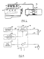
- FIG. 1 illustrates a fuel delivery system 10 in accordance with one presently preferred embodiment of the invention as comprising a self-contained electric-motor fuel pump 12 mounted within a canister 14 that is contained within and surrounded by a fuel tank 16.
- Fuel pump 12 delivers fuel under pressure through a fuel line 18 to a fuel rail 20 carried by an engine 22.
- a plurality of fuel injectors 24-30 are mounted between rail 20 and an engine air intake manifold 32 carried by engine 22, with the nozzles of the individual fuel injectors being positioned adjacent to the fuel/air intake ports 34-40 of associated cylinders of the engine.
- Combustion air may be supplied to manifold 32 through an air filter or the like at atmospheric pressure, or by a turbocharger or the like driven by the engine and supplying air at pressure that varies with engine operation and/or throttle demand, etc.
- Injectors 24-30 may be solenoid-activated, for example, responsive to an on-board engine control computer (not shown).
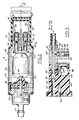
- FIGS. 2-3 illustrate self-contained electric-motor fuel pump 12 as comprising an inlet end cap 42 and an outlet end cap 44 coaxially interconnected by a cylindrical case 46 to form a hollow pump housing 48.
- a permanent magnet stator 50 is carried within case 46 surrounding an armature 52 that has electrical windings connected to a commutator plate 54.
- Armature 52 is journaled between end caps 42,44 by a shaft 56 for rotation within housing 48.
- Armature 52 is coupled to a vane or gear system 58 for pumping fuel from an inlet 60 through inlet end cap 42 to the volume of housing 48 surrounding armature 52, and thence through an outlet port 62 (FIG. 3) in outlet end cap 44 to fuel rail 20 (FIG. 1) through line 18.
- a pair of brushes 64,66 are respectively slidably received in end cap 44 in associated passages parallel to the axis of rotation of armature 52. Brushes 64,66 are respectively connected by wire conductors 68,70 to electrical terminals 71,72 on end cap 44 for coupling brushes 64,66, commutator plate 54 and armature 52 to a source of d.c. electrical power.
- a pair of springs 74,76 are captured in compression between respective brushes 64,66 and associated terminals 71,72 for urging brushes 64,66 into mechanical and electrical contact with commutator plate 54.
- pump 12 is similar to those disclosed in U.S. Patent Nos. 4,352,641 and 4,596,519 assigned to the assignee hereof to which reference may be had for more detailed background discussion of such pump structure.
- a check valve 78 (FIG. 3) is mounted in passage 62, and is urged against a seat 80 in end cap 44 by a coil spring 82 captured in compression between valve 78 and an outlet fitting 84. Valve 78 helps stabalize fuel flow and prevents reverse flow when pump 12 is turned off.
- a sleeve 83 on fitting 84 has a passage 85 that extends laterally from main fuel passage 87.
- a second check valve 86 within passage 85 is urged toward passage 87 against a seat 89 by a coil spring 88 captured in compression between valve 86 and a nut 90.
- Pressure of spring 88 against valve 86 is set by nut 90 such that an over-pressure in passage 87 and fuel line 18 causes check valve 86 to dump fuel from the pump outlet directly to fuel tank 16 (FIG. 1).
- a sleeve 92 on end cap 44 receives a cover 94 to form a sealed internal volume 95 that encloses terminals 71,72.
- An electronic circuitboard assembly 96 is captured by cover 94 against an opposing shoulder within sleeve 92. Electrical conductors 98,100 extend through volume 95 and connect circuitboard assembly 96 to terminal 71,72.
- An electronic pressure sensor 102 (FIG. 3) is mounted on end cap 44 between volume 95 and passage 87, and is responsive to pressure of fuel within passage 87 downstream of outlet check valve 78. Sensor 102 is connected to circuitboard assembly 96 by conductors 104.
- FIG. 4 is a functional block diagram of the fuel system electronics.
- Pressure sensor 102 which provides an electrical signal that varies as a direct and continuous (i.e., monotonic) function of fuel pump outlet pressure, is connected to an input of a pulse width modulation amplifier 106 on circuit assembly 96.
- a sensor 108 (FIGS. 1 and 4) is positioned within tank 16 and provides an electronic output signal, which varies as a direct and continuous (i.e., monotonic) function of fuel alcohol concentration, to a second input of amplifier 106.
- sensor 108 is indentically responsive to both methanol and ethanol.
- An amplifier 112 on circuit assembly 96 receives the electrical output of a fuel level sensor 114 (FIGS. 1 and 4) carried by canister 14. The output of amplifier 112 is coupled to a gauge 116 for indicating fuel level to an operator.
- sensor 114 is as disclosed in applicant's U.S. Patent No. 4,928,657.
- Circuit assembly 96 is also connected to the vehicle electrical system 110 and to electrical ground.
- amplifier 106 provides a pulsed d.c. signal to pump 12 having a duty cycle that decreases as a continuous function, preferably a linear function, of increasing pressure at sensor 102, and that increases as a direct continuing function, preferably linear or nearly linear, of increasing alcohol concentration at sensor 108.
- the pump motor is thus driven as an inverse function of pump outlet pressure so as to maintain constant fuel pressure at rail 20 (FIG. 1).
- pump speed is also automatically compensated for changes in fuel alcohol concentration.
- sensor 108 automatically measures average alcohol concentration and modifies pump speed accordingly.
- the quantity of fuel injected into the cylinders depends on fuel rail pressure, and therefore on fuel alcohol concentration in accordance with this aspect of the invention.
- the fuel delivery system hereinabove described addresses the aforementioned problems and deficiencies in the art, and includes a number of significant features.
- fuel alcohol concentration is measured and pump operation automatically compensated so that the fuel delivery system of the invention is suitable for use in conjunction with fuels of widely differing alcohol concentrations without any requirement or necessity for operator or service adjustment.
- This advantage of the invention will be of increasing importance as so-called alternative fuels of differing alcohol concentrations become more readily available.
- All of the fuel delivery system electronics including not only the pump control electronics but also the fuel level sensing electronics, are contained within a unitary pump design.
- the brush-type d.c. motor of the preferred embodiment of the fuel pump could be readily replaced by a brushless d.c. motor of any suitable construction, or by an a.c. motor, without departing in any way from the principles of the present invention in their broadest aspects.
- pump 12 would be mounted externally of tank 16, although an immersible pump is preferred.
Abstract
Description
- The present invention is directed to fuel delivery systems for internal combustion engines, and more particularly to a system for controlling fuel delivery as a function of fuel requirements.
- In engine fuel delivery systems of current design, fuel is typically fed by a constant-delivery pump from a fuel tank to the engine. A pressure regulator maintains constant fuel pressure at the engine, and excess fuel is returned from the engine to the fuel tank. Such return fuel carries engine heat to the fuel supply tank, and consequently increases temperature and vapor pressure in the fuel tank. Venting of excess vapor pressure to the atmosphere not only causes pollution problems, but also deleteriously affects fuel mileage. Excess fuel tank temperature can also cause vapor lock at the pump, particularly where fuel level is relatively low. Constant pump operation also increases energy consumption, while decreasing both fuel pump life and fuel filter life. It is therefore desirable not only to eliminate the necessity for the fuel return line from the engine to the supply tank (while still maintaining constant fuel pressure at the engine), but also to control pump operation as a function of fuel requirements at the engine both to maintain constant fuel pressure at the engine and to increase pump life.
- U.S. Patent No. 4,728,264 discloses a fuel delivery system in which a d.c. motor fuel pump delivers fuel under pressure from a supply tank to an engine. A pressure-sensitive switch, which may be contained within a unitary pump/motor housing, is responsive to fuel pump output pressure for applying a pulse width modulated d.c. signal to the pump motor, and thereby controlling pump operation so as to maintain constant pressure in the fuel delivery line to the engine independently of fuel demand. U.S. Patent No. 4,789,308 discloses a self-contained fuel pump that includes an electronic sensor in the pump outlet end cap responsive to fuel outlet pressure for modulating application of current to the pump motor and maintaining a constant pressure in the fuel delivery line to the engine. U.S. Patent No. 4,926,829 discloses a fuel delivery system in which a pressure sensor is coupled to the return line from the engine for detecting return flow of excess fuel to the supply tank. The output of a pulse width modulation amplifier to the fuel pump motor is controlled as function of the signal from the pressure sensor. The noted patents are all assigned to the applicant.
- Although the fuel delivery systems disclosed in the noted patents and application address and overcome a number of problems theretofore extant in the art, further improvements remain desirable. For example, it is desirable to provide a fuel delivery system that can be employed in conjunction with fuels of differing alcohol concentrations without requiring service or operator adjustment. Potential for energy release (BTU/unit volume) for gasoline is much greater than for alcohol. For this reason, quantity of fuel having 90% alcohol concentration delivered to the engine cylinders, for example, must be increased 50% as compared with straight gasoline to maintain constant throttle response and other engine operating characteristics. It has heretofore been proposed to accommodate increased fuel delivery by increasing injector activator time. However, the range of times necessary to accommodate all projected gasoline/alcohol mixtures exceeds the dynamic range of current injector technology.
- It is therefore a general object of the present invention to provide a fuel delivery system for internal combustion engines that automatically tailors fuel delivery to fuel alcohol concentration and type (either ethanol or methanol) without operator or service intervention. Another object of the present invention is to provide a fuel delivery system of the described character in which the fuel return line from the engine to the supply is eliminated, thereby reducing the problems of vapor generation and the like previously noted, and in which fuel delivery is maintained at constant pressure (for a given fuel alcohol concentration) by selectively controlling pump operation. It is yet another object of the present invention to provide a self-contained electric-motor fuel pump for use in systems of the described character that features an economical and reliable pump package assembly.
- A fuel delivery system for an internal combustion engine in accordance with the present invention includes a fuel supply with a fuel pump responsive to application of electrical power for supplying fuel under pressure. A fuel delivery mechanism, such as a fuel injector, is coupled to the fuel supply for controlled delivery of fuel from the supply to the engine. A sensor is responsive to concentration of alcohol in the fuel for providing a corresponding electrical signal, and electrical power applied to the pump is automatically varied as a function of the sensor output signal. Preferably, the pump includes a d.c. pump motor, and power is applied thereto by a pulse width modulation amplifier that produces a pulsed d.c. signal having a duty cycle that varies as a direct function of the alcohol sensor output signal.
- In the preferred implementation of the invention, a pressure sensor is coupled to the fuel delivery line between the pump and the engine for supplying an electrical signal that varies as a function of fuel delivery pressure. Electrical power is applied to the pump, preferably by a pulse width modulation amplifier as previously described, as a combined function of the pressure and alcohol-concentration sensor signals. That is, the output duty cycle of the pulse width modulation amplifier increases as a function of the alcohol sensor signal and decreases as a function of the pressure sensor signal. The pressure sensor and sensor-responsive electronics are mounted in the outlet end cap of a self-contained in-line immersible fuel pump assembly, and a pressure relief valve in the outlet end cap returns fuel to the supply in the event of excess pressure in the fuel delivery line.
- The invention, together with additional objects, features and advantages thereof, will be best understood from the following description, the appended claims and the accompanying drawings in which:
- FIG. 1 is a schematic diagram of a fuel delivery system in accordance with a presently preferred embodiment of the invention;
- FIG. 2 is a longitudinal bisection of the self-contained electric-motor fuel pump illustrated schematically in FIG. 1;
- FIG. 3 is a fragmentary sectional view taken substantially along the line 3 - 3 in FIG. 2; and
- FIG. 4 is a functional block diagram of the fuel delivery system electronics.
- FIG. 1 illustrates a fuel delivery system 10 in accordance with one presently preferred embodiment of the invention as comprising a self-contained electric-
motor fuel pump 12 mounted within acanister 14 that is contained within and surrounded by afuel tank 16.Fuel pump 12 delivers fuel under pressure through afuel line 18 to afuel rail 20 carried by anengine 22. A plurality of fuel injectors 24-30 are mounted betweenrail 20 and an engineair intake manifold 32 carried byengine 22, with the nozzles of the individual fuel injectors being positioned adjacent to the fuel/air intake ports 34-40 of associated cylinders of the engine. Combustion air may be supplied to manifold 32 through an air filter or the like at atmospheric pressure, or by a turbocharger or the like driven by the engine and supplying air at pressure that varies with engine operation and/or throttle demand, etc. Injectors 24-30 may be solenoid-activated, for example, responsive to an on-board engine control computer (not shown). - FIGS. 2-3 illustrate self-contained electric-
motor fuel pump 12 as comprising aninlet end cap 42 and anoutlet end cap 44 coaxially interconnected by a cylindrical case 46 to form ahollow pump housing 48. A permanent magnet stator 50 is carried within case 46 surrounding anarmature 52 that has electrical windings connected to acommutator plate 54.Armature 52 is journaled betweenend caps shaft 56 for rotation withinhousing 48.Armature 52 is coupled to a vane or gear system 58 for pumping fuel from aninlet 60 throughinlet end cap 42 to the volume ofhousing 48 surroundingarmature 52, and thence through an outlet port 62 (FIG. 3) inoutlet end cap 44 to fuel rail 20 (FIG. 1) throughline 18. A pair ofbrushes 64,66 are respectively slidably received inend cap 44 in associated passages parallel to the axis of rotation ofarmature 52.Brushes 64,66 are respectively connected bywire conductors electrical terminals 71,72 onend cap 44 forcoupling brushes 64,66,commutator plate 54 andarmature 52 to a source of d.c. electrical power. A pair ofsprings 74,76 are captured in compression betweenrespective brushes 64,66 and associatedterminals 71,72 forurging brushes 64,66 into mechanical and electrical contact withcommutator plate 54. To the extent thus far described,pump 12 is similar to those disclosed in U.S. Patent Nos. 4,352,641 and 4,596,519 assigned to the assignee hereof to which reference may be had for more detailed background discussion of such pump structure. - A check valve 78 (FIG. 3) is mounted in
passage 62, and is urged against aseat 80 inend cap 44 by acoil spring 82 captured in compression betweenvalve 78 and an outlet fitting 84. Valve 78 helps stabalize fuel flow and prevents reverse flow whenpump 12 is turned off. Asleeve 83 on fitting 84 has apassage 85 that extends laterally frommain fuel passage 87. Asecond check valve 86 withinpassage 85 is urged towardpassage 87 against a seat 89 by acoil spring 88 captured in compression betweenvalve 86 and anut 90. Pressure ofspring 88 againstvalve 86 is set bynut 90 such that an over-pressure inpassage 87 andfuel line 18 causescheck valve 86 to dump fuel from the pump outlet directly to fuel tank 16 (FIG. 1). Asleeve 92 onend cap 44 receives acover 94 to form a sealedinternal volume 95 that enclosesterminals 71,72. Anelectronic circuitboard assembly 96 is captured bycover 94 against an opposing shoulder withinsleeve 92. Electrical conductors 98,100 extend throughvolume 95 and connectcircuitboard assembly 96 toterminal 71,72. An electronic pressure sensor 102 (FIG. 3) is mounted onend cap 44 betweenvolume 95 andpassage 87, and is responsive to pressure of fuel withinpassage 87 downstream ofoutlet check valve 78.Sensor 102 is connected tocircuitboard assembly 96 byconductors 104. - FIG. 4 is a functional block diagram of the fuel system electronics.
Pressure sensor 102, which provides an electrical signal that varies as a direct and continuous (i.e., monotonic) function of fuel pump outlet pressure, is connected to an input of a pulsewidth modulation amplifier 106 oncircuit assembly 96. A sensor 108 (FIGS. 1 and 4) is positioned withintank 16 and provides an electronic output signal, which varies as a direct and continuous (i.e., monotonic) function of fuel alcohol concentration, to a second input ofamplifier 106. Preferably,sensor 108 is indentically responsive to both methanol and ethanol. Conventional dielectric sensors exhibit differing responsive characteristics to ethanol and methanol, although such sensors may be employed if either ethanol or methanol is mandated by government regulation or industry standard. Indeces of refraction of ethanol and methanol are substantially identical, and radiant energy sensors (e.g., optical) are currently preferred for this reason. An amplifier 112 oncircuit assembly 96 receives the electrical output of a fuel level sensor 114 (FIGS. 1 and 4) carried bycanister 14. The output of amplifier 112 is coupled to a gauge 116 for indicating fuel level to an operator. Preferably,sensor 114 is as disclosed in applicant's U.S. Patent No. 4,928,657.Circuit assembly 96 is also connected to the vehicleelectrical system 110 and to electrical ground. - In operation,
amplifier 106 provides a pulsed d.c. signal to pump 12 having a duty cycle that decreases as a continuous function, preferably a linear function, of increasing pressure atsensor 102, and that increases as a direct continuing function, preferably linear or nearly linear, of increasing alcohol concentration atsensor 108. For a given fuel alcohol concentration, the pump motor is thus driven as an inverse function of pump outlet pressure so as to maintain constant fuel pressure at rail 20 (FIG. 1). On the other hand, pump speed is also automatically compensated for changes in fuel alcohol concentration. Thus, in the event that the vehicle operator places fuels of differing alcohol concentration in the tank,sensor 108 automatically measures average alcohol concentration and modifies pump speed accordingly. For a given activation time at injectors 24-30, the quantity of fuel injected into the cylinders depends on fuel rail pressure, and therefore on fuel alcohol concentration in accordance with this aspect of the invention. - The fuel delivery system hereinabove described addresses the aforementioned problems and deficiencies in the art, and includes a number of significant features. For example, fuel alcohol concentration is measured and pump operation automatically compensated so that the fuel delivery system of the invention is suitable for use in conjunction with fuels of widely differing alcohol concentrations without any requirement or necessity for operator or service adjustment. This advantage of the invention will be of increasing importance as so-called alternative fuels of differing alcohol concentrations become more readily available. All of the fuel delivery system electronics, including not only the pump control electronics but also the fuel level sensing electronics, are contained within a unitary pump design. In this connection it will appreciated, of course, that the brush-type d.c. motor of the preferred embodiment of the fuel pump could be readily replaced by a brushless d.c. motor of any suitable construction, or by an a.c. motor, without departing in any way from the principles of the present invention in their broadest aspects. Likewise, pump 12 would be mounted externally of
tank 16, although an immersible pump is preferred.
Claims (22)
first sensor means for supplying a first electrical signal as a function of fuel pressure in said system, second sensor means for supplying a second electrical signal as a function of concentration of alcohol fuel at said supply, and means for applying electrical power to said pump as a combined function of said first and second signals.
said first sensor means being mounted on said other end cap so as to be responsive to fuel pressure at said outlet means,
said power-applying means comprising an electrical circuitboard assembly mounted on said other end cap and including connection means for receiving said first and second sensor signals and for applying electrical power to said motor.
means for providing an electrical signal as a function of concentration of alcohol in fuel at said supply, and means for applying power to said pump as a function of said electrical signal.
a fuel supply including a fuel pump responsive to application of electrical power for supplying fuel under pressure,
fuel delivery means on said engine,
a fuel line having one end connected to an outlet of said pump and a second end terminating at said fuel delivery means, said fuel line forming the sole interconnection between said fuel supply and said fuel delivery means,
means for applying electrical power to said pump,
a check valve in said fuel line for preventing reverse flow of fuel from said fuel delivery means and said pump, and
a pressure relief valve connected to said fuel line between said check valve and said fuel delivery means, said pressure relief valve being normally closed for blocking flow of fluid therethrough and being responsive to pressure in said fuel line above a preselected threshold to open and return fuel from said line to said supply.
a fuel supply with a self-contained electric-motor fuel pump responsive to application of electrical power for supplying fuel under pressure, said pump having a pair of coaxially spaced end caps and a case joining said end caps to form a pump housing, fuel inlet means in one of said end caps and fuel outlet means in the other of said end caps, a d.c. motor having an armature journaled for rotation within said housing, and means coupled to said armature for pumping fuel through said housing from said inlet means to said outlet means, fuel delivery means on said engine coupled to said supply for controlled delivery of fuel from said supply to said engine, and
means for applying electrical power to said pump comprising first sensor means mounted on said other end cap so as to be responsive to fuel pressure at said outlet means for supplying a first electrical signal as a function of fuel pressure in said system, second sensor means for supplying a second electrical signal as a function of a second predetermined condition of fuel at said supply, and means for applying electrical power to said pump as a combined function of said first and second signals,
said power-applying means comprising an electrical circuitboard assembly mounted on said other end cap and including connection means for receiving said first and second sensor signals and for applying electrical power to said motor.
a fuel supply including a fuel pump responsive to application of electrical power for supplying fuel under pressure,
fuel delivery means on said engine,
a fuel line having one end connected to an outlet of said pump and a second end terminating at said fuel delivery means, said fuel line forming the sole interconnection between said fuel supply and said fuel delivery means,
means for applying electrical power to said pump, including a sensor coupled to said line between said check valve and said fuel delivery means for providing an electrical signal as a function of fuel pressure in said line and means for applying electrical power to said pump as a function of said signal,
a check valve in said fuel line for preventing reverse flow of fuel from said fuel delivery means and said pump, and a pressure relief valve connected to said fuel line between said check valve and said fuel delivery means, said pressure relief valve being responsive to over-pressure in said fuel line to return fuel from said line to said supply.
a fuel supply including a fuel pump responsive to application of electrical power for supplying fuel under pressure,
fuel delivery means on said engine,
a fuel line having one end connected to an outlet of said pump and a second end terminating at said fuel delivery means, said fuel line forming the sole interconnection between said fuel supply and said fuel delivery means,
means for applying electrical power to said pump, including a sensor for providing an electrical signal as a function of fuel pressure in said line and means for applying electrical power to said pump as a function of said signal, a check valve in said fuel line for preventing reverse flow of fuel from said fuel delivery means and said pump,
a pressure relief valve connected to said fuel line between said check valve and said fuel delivery means, said pressure relief valve being response to over-pressure in said fuel line to return fuel from said line to said supply, and
a housing having a fuel passage extending therethrough, said sensor being mounted within said housing and communicating with said passage so as to be responsive to pressure of fuel in said passage, said pressure relief valve being mounted in said housing having a first end communicating within said passage, means at one end of said passage for receiving fuel from said pump, means at a second end of said passage for feeding fuel to said engine, and means at a second end of said pressure relief valve for returning fuel from said passage to said supply.
Applications Claiming Priority (2)
| Application Number | Priority Date | Filing Date | Title |
|---|---|---|---|
| US421810 | 1989-10-16 | ||
| US07/421,810 US5044344A (en) | 1989-10-16 | 1989-10-16 | Pressure-responsive fuel delivery system |
Publications (2)
| Publication Number | Publication Date |
|---|---|
| EP0423636A1 true EP0423636A1 (en) | 1991-04-24 |
| EP0423636B1 EP0423636B1 (en) | 1996-07-17 |
Family
ID=23672131
Family Applications (1)
| Application Number | Title | Priority Date | Filing Date |
|---|---|---|---|
| EP90119586A Expired - Lifetime EP0423636B1 (en) | 1989-10-16 | 1990-10-12 | Pressure-responsive fuel delivery system |
Country Status (4)
| Country | Link |
|---|---|
| US (1) | US5044344A (en) |
| EP (1) | EP0423636B1 (en) |
| JP (1) | JPH07113349B2 (en) |
| DE (1) | DE69027829T2 (en) |
Cited By (15)
| Publication number | Priority date | Publication date | Assignee | Title |
|---|---|---|---|---|
| WO1991019892A1 (en) * | 1990-06-15 | 1991-12-26 | Robert Bosch Gmbh | Process for adjusting the fuel feed in an internal combustion engine |
| US5148792A (en) * | 1992-01-03 | 1992-09-22 | Walbro Corporation | Pressure-responsive fuel delivery system |
| GB2273374A (en) * | 1992-12-11 | 1994-06-15 | Bosch Gmbh Robert | Fuel feed control means for an engine |
| EP0678664A2 (en) * | 1994-04-22 | 1995-10-25 | Mitsubishi Denki Kabushiki Kaisha | Fuel supplying apparatus and pressure regulator |
| US5482021A (en) * | 1993-11-11 | 1996-01-09 | Walbro Corporation | Air/fuel handling system for fuel injection engine |
| EP1059430A1 (en) * | 1999-06-10 | 2000-12-13 | BITRON S.p.A. | A controlled-pressure fuel-supply system for an internal combustion engine, particularly for motor vehicles |
| WO2002004804A1 (en) * | 2000-07-06 | 2002-01-17 | Bombardier Motor Corporation Of America | Dead-headed fuel delivery system using a single fuel pump |
| EP1306537A2 (en) * | 2001-10-23 | 2003-05-02 | Robert Bosch Gmbh | Method and apparatus for controlling an internal combustion engine |
| WO2009017922A1 (en) * | 2007-07-31 | 2009-02-05 | Illinois Tool Works Inc. | Fuel delivery module regulator valve |
| US8157542B2 (en) | 2007-06-15 | 2012-04-17 | Ti Automotive (Neuss) Gmbh | Brushless motor fuel pump with control electronics arrangement |
| CN101592103B (en) * | 2008-05-08 | 2013-02-27 | 福特环球技术公司 | On-board water addition for fuel separation system |
| WO2017077002A1 (en) * | 2015-11-03 | 2017-05-11 | Plastic Omnium Advanced Innovation And Research | Method for monitoring a quality of a chemical agent in a fluid used in a system of a motor vehicle. |
| EP3272199A1 (en) | 2016-07-20 | 2018-01-24 | Deere & Company | Mulching device for processing plant stumps on a field |
| DE102020202976A1 (en) | 2020-03-09 | 2021-09-09 | Deere & Company | Harvesting attachment with mulchers for processing plant stumps standing in a field with improved protection against thrown stones |
| EP3881665A1 (en) | 2020-03-18 | 2021-09-22 | Deere & Company | Mulching apparatus for processing plant stubble |
Families Citing this family (92)
| Publication number | Priority date | Publication date | Assignee | Title |
|---|---|---|---|---|
| US5233944A (en) * | 1989-08-08 | 1993-08-10 | Fuji Jukogyo Kabushiki Kaisha | Control apparatus for alcohol engine |
| JPH03242439A (en) * | 1990-02-16 | 1991-10-29 | Mitsubishi Motors Corp | Fuel blend rate detection method |
| JPH0472549A (en) * | 1990-07-13 | 1992-03-06 | Mitsubishi Electric Corp | Fuel form detecting device |
| DE4031009A1 (en) * | 1990-10-01 | 1992-04-23 | Pierburg Gmbh | METHOD AND DEVICE FOR THE USE OF FUELS WITH ALCOHOL ADDITIVES FOR AN INTERNAL COMBUSTION ENGINE |
| JP2790726B2 (en) * | 1990-11-30 | 1998-08-27 | 本田技研工業株式会社 | Engine evaporative fuel control system |
| US5170763A (en) * | 1990-12-28 | 1992-12-15 | Honda Giken Kogyo Kabushiki Kaisha | Air-fuel ratio control system for internal combustion engines |
| US5255656A (en) * | 1991-06-27 | 1993-10-26 | Borg-Warner Automotive, Inc. | Alcohol concentration sensor for automotive fuels |
| JP3306078B2 (en) * | 1991-09-06 | 2002-07-24 | 富士重工業株式会社 | Engine fuel injection control method |
| JPH05126006A (en) * | 1991-11-01 | 1993-05-21 | Honda Motor Co Ltd | Control device of fuel pump for internal combustion engine |
| US5195494A (en) * | 1992-02-27 | 1993-03-23 | Walbro Corporation | Fuel delivery system with outlet pressure regulation |
| US5542395A (en) * | 1993-11-15 | 1996-08-06 | Walbro Corporation | Temperature-compensated engine fuel delivery |
| US5291578A (en) * | 1992-06-15 | 1994-03-01 | First Switch, Inc. | Apparatus for controlling a vehicle fuel pump |
| US5235954A (en) * | 1992-07-09 | 1993-08-17 | Anatoly Sverdlin | Integrated automated fuel system for internal combustion engines |
| US5277166A (en) * | 1992-08-24 | 1994-01-11 | Ford Motor Company | Apparatus for controlling the rate of composition change of a fluid |
| US5471962A (en) * | 1992-10-15 | 1995-12-05 | Nippondenso Co., Ltd. | Fuel supply system for internal combustion engines |
| JP2812102B2 (en) * | 1992-10-15 | 1998-10-22 | 株式会社デンソー | Fuel supply device for internal combustion engine |
| US5577482A (en) * | 1992-10-15 | 1996-11-26 | Nippondenso Co., Ltd. | Fuel supply system for internal combustion engines |
| US5361742A (en) * | 1993-02-08 | 1994-11-08 | Walbro Corporation | Fuel pump manifold |
| JP3734281B2 (en) * | 1993-09-10 | 2006-01-11 | 株式会社デンソー | In-tank fuel pump |
| DE4335891A1 (en) * | 1993-10-21 | 1995-04-27 | Bosch Gmbh Robert | Method for filling the fuel supply system in an internal combustion engine |
| US5379741A (en) * | 1993-12-27 | 1995-01-10 | Ford Motor Company | Internal combustion engine fuel system with inverse model control of fuel supply pump |
| US5398655A (en) * | 1994-01-14 | 1995-03-21 | Walbro Corporation | Manifold referenced returnless fuel system |
| US5431143A (en) * | 1994-06-27 | 1995-07-11 | Ford Motor Company | Return fuel accumulating module |
| US5623910A (en) * | 1994-11-30 | 1997-04-29 | Walbro Corporation | Check and vent valve assembly |
| CA2163288A1 (en) * | 1994-12-30 | 1996-07-01 | William L. Learman | Engine demand fuel delivery system |
| US5699772A (en) * | 1995-01-17 | 1997-12-23 | Nippondenso Co., Ltd. | Fuel supply system for engines with fuel pressure control |
| US5469830A (en) * | 1995-02-24 | 1995-11-28 | The Cessna Aircraft Company | Fuel blending system method and apparatus |
| US5673670A (en) * | 1995-07-05 | 1997-10-07 | Ford Motor Company | Returnless fuel delivery system |
| US5642719A (en) * | 1995-09-11 | 1997-07-01 | Ford Motor Company | Automotive fuel delivery module with fuel level actuated reservoir |
| DE19627579A1 (en) * | 1996-07-09 | 1998-01-15 | Pierburg Ag | Fuel supply system for internal combustion engines |
| JP2002514710A (en) * | 1998-05-12 | 2002-05-21 | オービタル、エンジン、カンパニー(オーストラリア)、プロプライエタリ、リミテッド | Fuel vapor treatment system |
| DE60016990T2 (en) * | 1999-02-26 | 2005-12-29 | Walbro Corp., Cass City | Vehicle fuel system |
| JP2001207928A (en) | 2000-01-25 | 2001-08-03 | Denso Corp | Fuel supply quantity control device of internal combustion engine |
| DE10006622A1 (en) * | 2000-02-15 | 2001-08-16 | Bosch Gmbh Robert | Device for supplying a motor vehicle's internal combustion engine with fuel has a feeder unit driven by an electric motor to feed fuel from a reservoir to an internal combustion engine, also pressure-limiting and reverse flow valves. |
| US6622707B2 (en) | 2000-06-28 | 2003-09-23 | Delphi Technologies, Inc. | Electronic returnless fuel system |
| US6532941B2 (en) * | 2000-08-29 | 2003-03-18 | Delphi Technologies, Inc. | Electronic returnless fuel system |
| JP2002235625A (en) * | 2000-12-07 | 2002-08-23 | Mitsubishi Electric Corp | Electric fuel pump |
| US7306715B2 (en) * | 2002-08-05 | 2007-12-11 | Denso Corporation | Pump module |
| DE10300929B4 (en) * | 2003-01-13 | 2006-07-06 | Siemens Ag | Fuel injection system and method for determining the delivery pressure of a fuel pump |
| US7086493B2 (en) * | 2003-03-11 | 2006-08-08 | Ford Motor Company | Fuel system comprising vehicle impact shutoff |
| US7237539B2 (en) * | 2003-10-30 | 2007-07-03 | Philip Morris Usa Inc. | Control method and apparatus for use in an alcohol fueled internal combustion engine |
| US20050284448A1 (en) * | 2004-06-23 | 2005-12-29 | Forgue John R | Fuel pump system |
| US7168414B2 (en) * | 2004-09-03 | 2007-01-30 | Federal Mogul World Wide, Inc. | Marine vapor separator with bypass line |
| US7260988B2 (en) * | 2004-12-17 | 2007-08-28 | Visteon Global Technologies, Inc. | Fuel level sender circuit with alternating current direction |
| US7395786B2 (en) | 2005-11-30 | 2008-07-08 | Ford Global Technologies, Llc | Warm up strategy for ethanol direct injection plus gasoline port fuel injection |
| US8132555B2 (en) | 2005-11-30 | 2012-03-13 | Ford Global Technologies, Llc | Event based engine control system and method |
| US8434431B2 (en) * | 2005-11-30 | 2013-05-07 | Ford Global Technologies, Llc | Control for alcohol/water/gasoline injection |
| US7412966B2 (en) | 2005-11-30 | 2008-08-19 | Ford Global Technologies, Llc | Engine output control system and method |
| US7293552B2 (en) | 2005-11-30 | 2007-11-13 | Ford Global Technologies Llc | Purge system for ethanol direct injection plus gas port fuel injection |
| US7730872B2 (en) | 2005-11-30 | 2010-06-08 | Ford Global Technologies, Llc | Engine with water and/or ethanol direct injection plus gas port fuel injectors |
| US7302933B2 (en) * | 2005-11-30 | 2007-12-04 | Ford Global Technologies Llc | System and method for engine with fuel vapor purging |
| US7877189B2 (en) * | 2005-11-30 | 2011-01-25 | Ford Global Technologies, Llc | Fuel mass control for ethanol direct injection plus gasoline port fuel injection |
| US7647916B2 (en) * | 2005-11-30 | 2010-01-19 | Ford Global Technologies, Llc | Engine with two port fuel injectors |
| US7406947B2 (en) | 2005-11-30 | 2008-08-05 | Ford Global Technologies, Llc | System and method for tip-in knock compensation |
| US7594498B2 (en) * | 2005-11-30 | 2009-09-29 | Ford Global Technologies, Llc | System and method for compensation of fuel injector limits |
| US7357101B2 (en) * | 2005-11-30 | 2008-04-15 | Ford Global Technologies, Llc | Engine system for multi-fluid operation |
| US7640912B2 (en) * | 2005-11-30 | 2010-01-05 | Ford Global Technologies, Llc | System and method for engine air-fuel ratio control |
| DE102006001878A1 (en) * | 2006-01-13 | 2007-07-19 | Siemens Ag | Fuel conveyor |
| US7779813B2 (en) * | 2006-03-17 | 2010-08-24 | Ford Global Technologies, Llc | Combustion control system for an engine utilizing a first fuel and a second fuel |
| US7740009B2 (en) | 2006-03-17 | 2010-06-22 | Ford Global Technologies, Llc | Spark control for improved engine operation |
| US7389751B2 (en) * | 2006-03-17 | 2008-06-24 | Ford Global Technology, Llc | Control for knock suppression fluid separator in a motor vehicle |
| US7647899B2 (en) * | 2006-03-17 | 2010-01-19 | Ford Global Technologies, Llc | Apparatus with mixed fuel separator and method of separating a mixed fuel |
| US7533651B2 (en) | 2006-03-17 | 2009-05-19 | Ford Global Technologies, Llc | System and method for reducing knock and preignition in an internal combustion engine |
| US8267074B2 (en) | 2006-03-17 | 2012-09-18 | Ford Global Technologies, Llc | Control for knock suppression fluid separator in a motor vehicle |
| US8015951B2 (en) | 2006-03-17 | 2011-09-13 | Ford Global Technologies, Llc | Apparatus with mixed fuel separator and method of separating a mixed fuel |
| US7578281B2 (en) * | 2006-03-17 | 2009-08-25 | Ford Global Technologies, Llc | First and second spark plugs for improved combustion control |
| US7933713B2 (en) | 2006-03-17 | 2011-04-26 | Ford Global Technologies, Llc | Control of peak engine output in an engine with a knock suppression fluid |
| US7665428B2 (en) | 2006-03-17 | 2010-02-23 | Ford Global Technologies, Llc | Apparatus with mixed fuel separator and method of separating a mixed fuel |
| US7665452B2 (en) * | 2006-03-17 | 2010-02-23 | Ford Global Technologies, Llc | First and second spark plugs for improved combustion control |
| US7581528B2 (en) | 2006-03-17 | 2009-09-01 | Ford Global Technologies, Llc | Control strategy for engine employng multiple injection types |
| JP5128784B2 (en) * | 2006-04-19 | 2013-01-23 | 株式会社ニッキ | Engine fuel supply system |
| EP1849981A3 (en) * | 2006-04-26 | 2014-08-06 | Nikki Co., Ltd. | Fuel supply apparatus of engine |
| US7681554B2 (en) | 2006-07-24 | 2010-03-23 | Ford Global Technologies, Llc | Approach for reducing injector fouling and thermal degradation for a multi-injector engine system |
| US7909019B2 (en) | 2006-08-11 | 2011-03-22 | Ford Global Technologies, Llc | Direct injection alcohol engine with boost and spark control |
| US7287509B1 (en) * | 2006-08-11 | 2007-10-30 | Ford Global Technologies Llc | Direct injection alcohol engine with variable injection timing |
| US7431020B2 (en) * | 2006-11-30 | 2008-10-07 | Denso International America, Inc. | Adaptive fuel delivery module in a mechanical returnless fuel system |
| US7461628B2 (en) | 2006-12-01 | 2008-12-09 | Ford Global Technologies, Llc | Multiple combustion mode engine using direct alcohol injection |
| FR2911643B1 (en) * | 2007-01-19 | 2009-03-13 | Inergy Automotive Systems Res | METHOD AND SYSTEM FOR MONITORING THE OPERATION OF A PUMP |
| US7526374B2 (en) * | 2007-03-14 | 2009-04-28 | Gm Global Technology Operations, Inc. | Ethanol compensated fuel density for fuel consumed calculation |
| US20080264387A1 (en) * | 2007-04-27 | 2008-10-30 | Paul Spivak | Method and System for Adjusting Engine Fuel Rates by Adjusting Fuel Pressure |
| US8214130B2 (en) | 2007-08-10 | 2012-07-03 | Ford Global Technologies, Llc | Hybrid vehicle propulsion system utilizing knock suppression |
| US7676321B2 (en) * | 2007-08-10 | 2010-03-09 | Ford Global Technologies, Llc | Hybrid vehicle propulsion system utilizing knock suppression |
| US7971567B2 (en) | 2007-10-12 | 2011-07-05 | Ford Global Technologies, Llc | Directly injected internal combustion engine system |
| US8118009B2 (en) | 2007-12-12 | 2012-02-21 | Ford Global Technologies, Llc | On-board fuel vapor separation for multi-fuel vehicle |
| US8550058B2 (en) | 2007-12-21 | 2013-10-08 | Ford Global Technologies, Llc | Fuel rail assembly including fuel separation membrane |
| US8141356B2 (en) | 2008-01-16 | 2012-03-27 | Ford Global Technologies, Llc | Ethanol separation using air from turbo compressor |
| WO2012051122A2 (en) * | 2010-10-10 | 2012-04-19 | Bex America, Llc | Method and apparatus for converting diesel engines to blended gaseous and diesel fuel engines |
| JP5375859B2 (en) * | 2011-03-11 | 2013-12-25 | トヨタ自動車株式会社 | Fuel supply system for internal combustion engine |
| DE102013206424B3 (en) * | 2013-04-11 | 2014-07-10 | Ford Global Technologies, Llc | Method for determining target pressure in fuel distributor block of injection system of motor vehicle, involves determining calculation pressure from sum of chamber pressure and square of ratio of fuel mass fraction and pulse width |
| US9752515B1 (en) | 2017-04-03 | 2017-09-05 | James A. Stroup | System, method, and apparatus for injecting a gas in a diesel engine |
| DE102017209045A1 (en) * | 2017-05-30 | 2018-12-06 | Robert Bosch Gmbh | Filter housing and intermediate bottom |
| US10816427B2 (en) | 2018-05-09 | 2020-10-27 | Ford Global Technologies, Llc | Integrated fuel composition and pressure sensor |
Citations (7)
| Publication number | Priority date | Publication date | Assignee | Title |
|---|---|---|---|---|
| FR1570162A (en) * | 1967-06-12 | 1969-06-06 | ||
| US4404944A (en) * | 1980-08-07 | 1983-09-20 | Nissan Motor Co., Ltd. | Fuel supply system for an injection-type internal combustion engine |
| US4706630A (en) * | 1986-02-07 | 1987-11-17 | Ford Motor Company | Control system for engine operation using two fuels of different volatility |
| US4789308A (en) * | 1986-10-10 | 1988-12-06 | Walbro Corporation | Self-contained electric fuel pump with output pressure regulation |
| WO1990003565A1 (en) * | 1988-09-27 | 1990-04-05 | The Standard Oil Company | Sensor and method for measuring alcohol concentration in an alcohol-gasoline mixture |
| US4926829A (en) * | 1988-11-28 | 1990-05-22 | Walbro Corporation | Pressure-responsive fuel delivery system |
| US4928657A (en) * | 1989-03-02 | 1990-05-29 | Walbro Corporation | In-tank fuel reservoir with fuel level sensor |
Family Cites Families (14)
| Publication number | Priority date | Publication date | Assignee | Title |
|---|---|---|---|---|
| US3935851A (en) * | 1973-12-26 | 1976-02-03 | Chrysler Corporation | Fuel metering system for spark ignition engines |
| US4248194A (en) * | 1979-08-23 | 1981-02-03 | Trw Inc. | Method and apparatus for controlling the operation of a pump |
| IT1133295B (en) * | 1980-05-08 | 1986-07-09 | Weber Spa | ELECTRICALLY OPERATED FUEL PUMP, SUITABLE FOR USE IN INJECTION SYSTEMS FOR INTERNAL COMBUSTION ENGINES WITH COMMAND IGNITION |
| JPS5728831A (en) * | 1980-07-28 | 1982-02-16 | Nissan Motor Co Ltd | Fuel controller |
| JPS5762958A (en) * | 1980-09-30 | 1982-04-16 | Mitsuba Denki Seisakusho:Kk | Motor driven fuel pump |
| JPS5776256A (en) * | 1980-10-30 | 1982-05-13 | Toyota Motor Corp | Heating device for suction air |
| JPS57140556A (en) * | 1981-02-24 | 1982-08-31 | Nippon Denso Co Ltd | Electric motor driven fuel pump device |
| US4501253A (en) * | 1982-12-13 | 1985-02-26 | Consolidated Natural Gas Service Company, Inc. | On-board automotive methane compressor |
| FR2542092B1 (en) * | 1983-03-03 | 1986-02-28 | Inst Francais Du Petrole | METHOD AND DEVICE FOR DETERMINING THE COMPOSITION OF AN ALCOHOL-PETROL MIXTURE, SUITABLE FOR AUTOMATIC ADJUSTMENT OF ENGINES FUEL COMBUSTIBLE WITH A VARIABLE ALCOHOL CONTENT |
| JPS61218746A (en) * | 1985-03-25 | 1986-09-29 | Toyota Motor Corp | Air-fuel ratio controller of internal-combustion engine using alcohol-mixed fuel |
| JPS62192633A (en) * | 1986-02-19 | 1987-08-24 | Ngk Spark Plug Co Ltd | Mixing ratio sensor for alcohol mixed fuel |
| JPH0681931B2 (en) * | 1986-06-25 | 1994-10-19 | 日本電装株式会社 | Fuel pump controller |
| US4756291A (en) * | 1987-04-27 | 1988-07-12 | Ford Motor Company | Pressure control for the fuel system of an internal combustion engine |
| JPH0199056U (en) * | 1987-12-23 | 1989-07-03 |
-
1989
- 1989-10-16 US US07/421,810 patent/US5044344A/en not_active Expired - Lifetime
-
1990
- 1990-10-12 DE DE69027829T patent/DE69027829T2/en not_active Expired - Fee Related
- 1990-10-12 EP EP90119586A patent/EP0423636B1/en not_active Expired - Lifetime
- 1990-10-16 JP JP2275506A patent/JPH07113349B2/en not_active Expired - Fee Related
Patent Citations (7)
| Publication number | Priority date | Publication date | Assignee | Title |
|---|---|---|---|---|
| FR1570162A (en) * | 1967-06-12 | 1969-06-06 | ||
| US4404944A (en) * | 1980-08-07 | 1983-09-20 | Nissan Motor Co., Ltd. | Fuel supply system for an injection-type internal combustion engine |
| US4706630A (en) * | 1986-02-07 | 1987-11-17 | Ford Motor Company | Control system for engine operation using two fuels of different volatility |
| US4789308A (en) * | 1986-10-10 | 1988-12-06 | Walbro Corporation | Self-contained electric fuel pump with output pressure regulation |
| WO1990003565A1 (en) * | 1988-09-27 | 1990-04-05 | The Standard Oil Company | Sensor and method for measuring alcohol concentration in an alcohol-gasoline mixture |
| US4926829A (en) * | 1988-11-28 | 1990-05-22 | Walbro Corporation | Pressure-responsive fuel delivery system |
| US4928657A (en) * | 1989-03-02 | 1990-05-29 | Walbro Corporation | In-tank fuel reservoir with fuel level sensor |
Cited By (26)
| Publication number | Priority date | Publication date | Assignee | Title |
|---|---|---|---|---|
| WO1991019892A1 (en) * | 1990-06-15 | 1991-12-26 | Robert Bosch Gmbh | Process for adjusting the fuel feed in an internal combustion engine |
| US5148792A (en) * | 1992-01-03 | 1992-09-22 | Walbro Corporation | Pressure-responsive fuel delivery system |
| FR2685938A1 (en) * | 1992-01-03 | 1993-07-09 | Walbro Corp | FUEL DELIVERY CIRCUIT AND METHOD OF REDUCING FUEL VAPORIZATION. |
| FR2700188A1 (en) * | 1992-01-03 | 1994-07-08 | Walbro Corp | A method of reducing the vaporization of fuel in an internal combustion engine. |
| GB2273374A (en) * | 1992-12-11 | 1994-06-15 | Bosch Gmbh Robert | Fuel feed control means for an engine |
| FR2699225A1 (en) * | 1992-12-11 | 1994-06-17 | Bosch Gmbh Robert | Installation to adapt the amount of fuel injected into a heat engine. |
| US5482021A (en) * | 1993-11-11 | 1996-01-09 | Walbro Corporation | Air/fuel handling system for fuel injection engine |
| EP0678664A2 (en) * | 1994-04-22 | 1995-10-25 | Mitsubishi Denki Kabushiki Kaisha | Fuel supplying apparatus and pressure regulator |
| EP0678664A3 (en) * | 1994-04-22 | 1996-05-15 | Mitsubishi Electric Corp | Fuel supplying apparatus and pressure regulator. |
| US5655504A (en) * | 1994-04-22 | 1997-08-12 | Mitsubishi Denki Kabushiki Kaisha | Fuel supplying apparatus and pressure regulator |
| EP1059430A1 (en) * | 1999-06-10 | 2000-12-13 | BITRON S.p.A. | A controlled-pressure fuel-supply system for an internal combustion engine, particularly for motor vehicles |
| WO2002004804A1 (en) * | 2000-07-06 | 2002-01-17 | Bombardier Motor Corporation Of America | Dead-headed fuel delivery system using a single fuel pump |
| EP1306537A2 (en) * | 2001-10-23 | 2003-05-02 | Robert Bosch Gmbh | Method and apparatus for controlling an internal combustion engine |
| EP1306537A3 (en) * | 2001-10-23 | 2005-11-16 | Robert Bosch Gmbh | Method and apparatus for controlling an internal combustion engine |
| US8157542B2 (en) | 2007-06-15 | 2012-04-17 | Ti Automotive (Neuss) Gmbh | Brushless motor fuel pump with control electronics arrangement |
| WO2009017922A1 (en) * | 2007-07-31 | 2009-02-05 | Illinois Tool Works Inc. | Fuel delivery module regulator valve |
| US7878181B2 (en) | 2007-07-31 | 2011-02-01 | Illinois Tool Works Inc. | Fuel delivery module regulator valve |
| CN101592103B (en) * | 2008-05-08 | 2013-02-27 | 福特环球技术公司 | On-board water addition for fuel separation system |
| WO2017077002A1 (en) * | 2015-11-03 | 2017-05-11 | Plastic Omnium Advanced Innovation And Research | Method for monitoring a quality of a chemical agent in a fluid used in a system of a motor vehicle. |
| EP3272199A1 (en) | 2016-07-20 | 2018-01-24 | Deere & Company | Mulching device for processing plant stumps on a field |
| DE102017207337A1 (en) | 2016-07-20 | 2018-01-25 | Deere & Company | Mulching device for processing plant stumps standing on a field |
| US10398080B2 (en) | 2016-07-20 | 2019-09-03 | Deere & Company | Mulching device for processing plant stubble on a field |
| DE102020202976A1 (en) | 2020-03-09 | 2021-09-09 | Deere & Company | Harvesting attachment with mulchers for processing plant stumps standing in a field with improved protection against thrown stones |
| BE1028095A1 (en) | 2020-03-09 | 2021-09-20 | Deere & Co | Harvesting attachment with mulchers for processing plant stumps standing in a field with improved protection against thrown stones |
| EP3881665A1 (en) | 2020-03-18 | 2021-09-22 | Deere & Company | Mulching apparatus for processing plant stubble |
| DE102020203474A1 (en) | 2020-03-18 | 2021-09-23 | Deere & Company | Mulching device for processing plant stubble |
Also Published As
| Publication number | Publication date |
|---|---|
| DE69027829D1 (en) | 1996-08-22 |
| US5044344A (en) | 1991-09-03 |
| JPH03242457A (en) | 1991-10-29 |
| EP0423636B1 (en) | 1996-07-17 |
| JPH07113349B2 (en) | 1995-12-06 |
| DE69027829T2 (en) | 1996-11-21 |
Similar Documents
| Publication | Publication Date | Title |
|---|---|---|
| US5044344A (en) | Pressure-responsive fuel delivery system | |
| US5120201A (en) | Brushless DC fuel pump responsive to pressure sensor | |
| US6453878B1 (en) | Electrically controlled fuel supply pump for internal combustion engine | |
| US5411002A (en) | Internal combustion engine fuel injection apparatus and system | |
| US4920942A (en) | Method and apparatus for supplying fuel to internal combustion engines | |
| US4926829A (en) | Pressure-responsive fuel delivery system | |
| US6889656B1 (en) | Fuel supply system of an internal combustion engine | |
| US4951636A (en) | Constant pressure-differential fuel injection system | |
| US5609140A (en) | Fuel supply system for an internal combustion engine | |
| US5287833A (en) | Lubricating oil supplying system for two cycle engine | |
| EP0299337A2 (en) | Fuel injection system for an internal combustion engine | |
| EP0644322A1 (en) | Variable pressure deadheaded fuel rail fuel pump control system | |
| US6318344B1 (en) | Dead-headed fuel delivery system using a single fuel pump | |
| EP0773361A1 (en) | Fuel delivery system for an internal combustion engine | |
| CA1278474C (en) | Closed end fuel injection system | |
| CA2163288A1 (en) | Engine demand fuel delivery system | |
| US6453877B1 (en) | Fuel delivery system using two pressure regulators with a single electric fuel pump | |
| US4807583A (en) | Fuel pumping apparatus | |
| US5878724A (en) | Diesel vehicle primary fuel pump driven by return fuel energy | |
| US5337718A (en) | Electronic fuel injection system with heat-pressure response | |
| EP0320462B1 (en) | A fuel-injection pump with variable cylinder capacity for diesel engine injection systems | |
| US5341785A (en) | Fuel delivery system for internal combustion engines | |
| US6925990B1 (en) | Method for controlling fuel pressure for a fuel injected engine | |
| EP0475515B1 (en) | Device for measuring the consumption of fuel in an internal combustion engine | |
| US7383821B2 (en) | Apparatus for pumping fuel from a tank to an internal combustion engine, and method for pressure detection |
Legal Events
| Date | Code | Title | Description |
|---|---|---|---|
| PUAI | Public reference made under article 153(3) epc to a published international application that has entered the european phase |
Free format text: ORIGINAL CODE: 0009012 |
|
| AK | Designated contracting states |
Kind code of ref document: A1 Designated state(s): DE FR GB |
|
| 17P | Request for examination filed |
Effective date: 19911015 |
|
| 17Q | First examination report despatched |
Effective date: 19930316 |
|
| GRAH | Despatch of communication of intention to grant a patent |
Free format text: ORIGINAL CODE: EPIDOS IGRA |
|
| GRAA | (expected) grant |
Free format text: ORIGINAL CODE: 0009210 |
|
| AK | Designated contracting states |
Kind code of ref document: B1 Designated state(s): DE FR GB |
|
| ET | Fr: translation filed | ||
| GRAH | Despatch of communication of intention to grant a patent |
Free format text: ORIGINAL CODE: EPIDOS IGRA |
|
| REF | Corresponds to: |
Ref document number: 69027829 Country of ref document: DE Date of ref document: 19960822 |
|
| PG25 | Lapsed in a contracting state [announced via postgrant information from national office to epo] |
Ref country code: GB Effective date: 19961017 |
|
| PLBE | No opposition filed within time limit |
Free format text: ORIGINAL CODE: 0009261 |
|
| STAA | Information on the status of an ep patent application or granted ep patent |
Free format text: STATUS: NO OPPOSITION FILED WITHIN TIME LIMIT |
|
| GBPC | Gb: european patent ceased through non-payment of renewal fee |
Effective date: 19961017 |
|
| 26N | No opposition filed | ||
| PGFP | Annual fee paid to national office [announced via postgrant information from national office to epo] |
Ref country code: FR Payment date: 19990917 Year of fee payment: 10 |
|
| PG25 | Lapsed in a contracting state [announced via postgrant information from national office to epo] |
Ref country code: FR Free format text: LAPSE BECAUSE OF NON-PAYMENT OF DUE FEES Effective date: 20010629 |
|
| REG | Reference to a national code |
Ref country code: FR Ref legal event code: ST |
|
| PGFP | Annual fee paid to national office [announced via postgrant information from national office to epo] |
Ref country code: DE Payment date: 20061130 Year of fee payment: 17 |
|
| PG25 | Lapsed in a contracting state [announced via postgrant information from national office to epo] |
Ref country code: DE Free format text: LAPSE BECAUSE OF NON-PAYMENT OF DUE FEES Effective date: 20080501 |