EP0425184A2 - Shielding strip for a computer - Google Patents
Shielding strip for a computer Download PDFInfo
- Publication number
- EP0425184A2 EP0425184A2 EP90311384A EP90311384A EP0425184A2 EP 0425184 A2 EP0425184 A2 EP 0425184A2 EP 90311384 A EP90311384 A EP 90311384A EP 90311384 A EP90311384 A EP 90311384A EP 0425184 A2 EP0425184 A2 EP 0425184A2
- Authority
- EP
- European Patent Office
- Prior art keywords
- retainer
- drive
- housing
- spring
- bays
- Prior art date
- Legal status (The legal status is an assumption and is not a legal conclusion. Google has not performed a legal analysis and makes no representation as to the accuracy of the status listed.)
- Granted
Links
Images


Classifications
-
- G—PHYSICS
- G06—COMPUTING; CALCULATING OR COUNTING
- G06F—ELECTRIC DIGITAL DATA PROCESSING
- G06F1/00—Details not covered by groups G06F3/00 - G06F13/00 and G06F21/00
- G06F1/16—Constructional details or arrangements
-
- H—ELECTRICITY
- H05—ELECTRIC TECHNIQUES NOT OTHERWISE PROVIDED FOR
- H05K—PRINTED CIRCUITS; CASINGS OR CONSTRUCTIONAL DETAILS OF ELECTRIC APPARATUS; MANUFACTURE OF ASSEMBLAGES OF ELECTRICAL COMPONENTS
- H05K9/00—Screening of apparatus or components against electric or magnetic fields
- H05K9/0007—Casings
- H05K9/0015—Gaskets or seals
- H05K9/0016—Gaskets or seals having a spring contact
-
- G—PHYSICS
- G06—COMPUTING; CALCULATING OR COUNTING
- G06F—ELECTRIC DIGITAL DATA PROCESSING
- G06F1/00—Details not covered by groups G06F3/00 - G06F13/00 and G06F21/00
- G06F1/16—Constructional details or arrangements
- G06F1/18—Packaging or power distribution
- G06F1/181—Enclosures
- G06F1/182—Enclosures with special features, e.g. for use in industrial environments; grounding or shielding against radio frequency interference [RFI] or electromagnetical interference [EMI]
Definitions
- This invention relates in general to apparatus for reducing the emission of electromagnetic interference (EMI) and, more particularly, to a shielding strip for reducing EMI from computers.
- EMI electromagnetic interference
- a computer housing is described herein which is capable of accommodating several disk drives or similar devices in a plurality of bays within the housing.
- a removable drive retainer/cover structure covers the disk drives.
- the housing is fabricated such that the drives are readily removable.
- a shielding strip for a computer including an electrically conductive housing and a non-conductive drive mounting structure situated within said housing, said drive mounting structure including a plurality of bays which communicate with an opening in said housing, a electrically conductive retainer being situated over said opening to hold said disk drives in said bays, said strip comprising: a longitudinal main portion extending along a first side of said housing adjacent said opening and situated between the first side of said housing and said drive mounting structure, and a plurality of spring structures extending laterally away from said main portion and toward said bays, each of said spring structures including a first spring portion for contacting said retainer and a second spring portion for contacting a conductive portion of a disk drive mounted in a respective bay.
- the invention enables a grounding apparatus to be provided which grounds the disk drives and the removable cover structure to the housing in such a fashion as to reduce undesired EMS and to yet permit ready removal of disk drives from the computer.
- the invention further enables an enclosure for a computer to be provided, said enclosure comprising: an electrically conductive case and a non-conductive mounting structure situated within said case, said mounting structure including means defining a plurality of bays for receiving devices, a retainer removably connectable to said case to hold devices within said bays, a shielding strip and grounding strap, for providing a conductive path for a device mounted in a respective bay, the main body portion of the shielding strip extending longitudinally along a first side of the case, being in intimate conductive contact therewith, and located intermediate the first side of the case and the mounting structure.
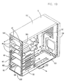
- FIG. 1A is an exploded perspective view of a personal computer assembly 10 which includes an enclosure or case 15 and a disk drive support structure 20.
- Case 15 is fabricated from electrically conductive material and exhibits a generally parallelepiped shape. More specifically, case 15 includes front and back members 15A and 15B, top and bottom members 15C and 15D, and a side member 15E. The remaining sixth side of the parallelepiped geometry of case 15 is open as seen in FIG. 1A. An open chamber 25 is thus formed within case 15 for receiving computer components and related structures such as disk drive support structure 20.
- disk drive support structure 20 When installed in housing 15, as seen in FIG. 1B, disk drive support structure 20 spans substantially the entire interior surface of front member 15A and a substantial portion of the interior of case 15. Support structure 20 is anchored at several locations within case 15 and is configured to provide case 15 with additional structural integrity as will be discussed later in more detail.
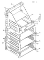
- Disk drive support structure 20 is fabricated from electrically insulative, substantially structurally rigid material, such as polycarbonate/ABS plastic, for example. Disk drive support structure 20 is illustrated in more detail in the front right side perspective view of FIG. 2.
- full height disk drive is used to describe a particular size of disk drive and the term “half height” is used to describe a disk drive which exhibits a height which is approximately half the height of a "full height” disk drive. Both hard disk drives and floppy disk drives are available in either full height or half height versions.
- Disk drive support structure 20 includes a plurality of bays for housing a plurality of disk drives stacked one atop the other. More specifically, structure 20 includes bay C1 and bay C2 which together form a bay C. Bay C is capable of housing a single full height disk drive or two half height disk drives in bays C1 and C2, respectively. Structure 20 further includes a bay D which is substantially similar to bay C. Bay D includes bays D1 and D2. Bay D is capable of housing a single full height disk drive or two half height disk drives in bays D1 and D2, respectively. Disk drive support structure 20 also includes a half height bay E as shown in FIG. 2 in this particular embodiment of the invention. Disk drive support structure 20 still further includes bays A and B in the upper portion of structure 20 as shown in FIG. 2.
- disk drive support structure 20 includes substantially parallel side walls 30 and 35.
- Structure 20 further includes a front wall 40 which is integrally molded to and which extends between side walls 30 and 35 as shown in FIG. 2 and in the right side rear perspective view of structure 20 shown in FIG. 3.
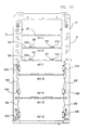
- front wall 40 of structure 20 includes a plurality of openings 45, 50 and 55 which are aligned with bays C, D and E to provide paths through which disk drives can be installed in such chambers.
- Bays A and B have similar openings. From FIG. 2, it is seen that bays A, B, C, D and E are formed between substantially parallel shelves 20A, 20B, 20C, 20D, 20E and 20F which extend between side walls 30 and 35 of structure 20. Shelf 20F is the topmost shelf of shelves 20A-20F. Shelves 20A, 20B, 20C, 20D, 20E and 20F are stacked one above the other in spaced apart relationship to form bays A, B, C, D and E therebetween.
- front wall 40 includes a plurality of bolt holes 60 to enable disk drive support structure 20 to be securely bolted to the interior of case 15 as will now be described.
- front member 15A of case 15 includes a plurality of bolt receiving holes 65 which are aligned with corresponding bolt holes 60 in structure 20 when structure 20 is situated within case 15.
- Bolts 70 are then located in respective hole pairs 60-65 and fixed with appropriated fasteners to hold front wall 40 of structure 20 firmly to front member 15A of housing 15,
- disk drive support structure 20 includes four mounting pads 70, each including a respective hole 75.
- holes 75 of structure 20 align with corresponding respective threaded holes 80 in side member 15E.
- FIG. 3 a portion of side member 15E adjacent a representative hole 80 is shown in FIG. 3 at approximately four times actual size.
- FIG. 4 A left side perspective view of structure 20 is shown in FIG. 4 to more clearly depict mounting pads 70, holes 75 and side wall 35 of disk drive support structure 20. Respective threaded bolts 85 are screwed through each of hole pairs 75-80 to securely hold side wall 35 of structure 20 to side member 15E of case 15.
- drive support structure 20 extends across the majority of the interior surface of front member 15A both laterally and longitudinally. In this particular embodiment, support structure 20 extends along the entirety of the interior surface of front member 15A. Moreover, support structure 20 is fixedly or rigidly attached to two substantially perpendicular members of case 15, namely front member 15A and side member 15E, as describe above.
- support structure 20 When disk drive support structure 20 is mounted within case 15 in this manner, the structural integrity of case 15 is substantially increased.
- Support structure 20 houses and supports multiple disk drives while simultaneously improving the substantial structural integrity of case 15. More specifically, the multi-chamber nature of structure 20 acts to reinforce case 15 and enhances the rigidity of case 15 against moments of force which would otherwise cause case 15 to undesirably twist and deform.
- FIG. 5 is an enlarged and exploded right side perspective view of the lower bay C portion of disk drive support structure 20, the entirety of which was shown earlier in FIG. 2.
- Bay D is substantially identical to bay C and thus the following discussion of bay C will apply to bay D as well.
- Half height drives or full height drives generally have respective plastic rails mounted to the two opposed side surfaces thereof to permit such drives to slide in and out of fixed, non-removable rail guides which are typically situated within a computer. It is desirable to have maximum flexibility in the choice of placement of one full height or two half height drives in bays C and D. Moreover, it is desirable to provide a reasonable amount of clearance or sway space between the sides of a hard disk mounted in a bay to avoid or reduce shock damage to such hard drives.
- Bay C is provided with removable drive support guides 90 as shown in FIG. 5.
- the upper portion of bay C includes support guide receiving channels 95A and 95B located in side walls 35 and 30, respectively, each of which is capable of receiving a respective removable support guide 90 therein as will be discussed subsequently in more detail.
- the lower portion of bay C includes rail receiving guides 100A and 100B which are integrally formed into side walls 35 and 30, respectively, as shown in FIG. 5.
- a pair of guide rails (described later) are mounted on the opposed sides of a full height or half height drive such that the rails can be slid into receiving guides 100A and 100B.
- Support guides 90 mounted in guide receiving channels 95A and 95B can receive a half height drive with rails mounted as described above providing a full height drive is not mounted in receiving guides 100A and 100B therebelow.
- support guides 90 are substantially rectangular in shape and include opposed ends 105 and 100, and further include opposed sides 115 and 120.
- Guide receiving channels 95A and 95B include slots 125 and 130 laterally oriented along portions of such channels for facilitating the attachment of support guides 90 to side walls 35 and 30 as will now be described.
- Slot 125 includes opposed ends 125A and 125B.
- Slot 130 includes opposed ends 130A and 130B.
- Support guides 90 include flexible snaps or latches 135 and 140 which are spaced apart by a predetermined distance approximately equal to the length of slots 125 and 130. For purposes of example, the placement of a support guide 90 in slot 130 will now be discussed although it should be appreciated that a support guide 90 can be situated in slot 125 as well using the same technique.
- a pair of stops 145 and 150 are situated adjacent latch 135 as shown in FIG. 5.
- a pair of stops 155 and 160 are situated adjacent latch 140.
- Latch 135 includes a flexible arm 135A extending from guide 90.
- a catch or protrusion 135B is situated at the end of arm 135A such that as stop pair 145-150 of guide 90 is placed in slot 130, arm 135A deflects until protrusion 135B catches and holds to slot end 130A.
- latch 140 includes a flexible arm 140A extending from guide 90 and a catch or protrusion 140B at the end of arm 140. Arm 140B similarly deflects when stop pair 155-160 of guide 90 is placed in slot 130. Protrusion 140B then catches on end 130B to hold guide 90 in position in slot 130 of channel 95B.
- latches 135 and 140 are living snap members which are integrally formed into guide 90. Support guide 90 is easily removed from channel 95B by pulling guide 90 away from slot 130 with sufficient force to deflect arms 135A and 140A and overcome the snap action of latches 135 and 140.
- Side 115 of guide 90 includes a channel 165 for receiving a disk drive rail or other sliding structure.
- drive support guides 90 are removably mounted in channels 95A and 95B as described above, a half height disk drive having two rails mounted on the respective sides thereof as described earlier is readily mounted in the upper portion of bay C by sliding such rails into the channels 165 of support guides 90.
- guide 90 To facilitate the sliding of a rail into channel 165 of support guide 90, guide 90 includes a pair of protrusions 175 and 180 which are flared apart at ends 175A and 180A to enhance the alignment of a rail within channel 165 as the rail initially approaches and engages channel 165.
- FIG. 6 is an exploded perspective view of the front portion of personal computer assembly 10 which demonstrates the different drive combinations which drive support structure 20 is capable of housing.
- the lower portion of drive C is designated bay C1 and the upper portion of bay C is designated bay C2.
- the lower portion of drive D is designated bay D1 and the upper portion of bay D is designated bay D2.
- Disk drive support structure 20 supports all of these types of drives as seen in the examples portrayed in FIG. 6. While bays C and D of structure 20 are full height bays, bays C1, C2, D1 and D2 are half height bays.
- snap-in support guides 90 are removed from channels 95A and 95B (not fully shown) in upper bay C2. Then, rails 190 and 190′, situated on the opposed sides of drive 185, are slid into receiving guides 100B and 100A, respectively, as seen more clearly in the front view of chamber C shown in FIG. 7.
- each of drives 195 in bay of snap-in support guides 90 is installed in channels 95A and 95B of upper bay C2.
- each of drives 195 is installed in an adapter tray 200 which includes integral conductive side rails 205 and 210 as will be discussed later in detail.
- side rails 205 and 210 slide into receiving guides 100A and 100B.
- side rails 205 and 210 slide into respective channels 165 of support guides 90.
- bay D is substantially similar to bay C.
- bay D can likewise accommodate a full height disk drive 185, two half height disk drives 215 or two adapter tray-mounted disk drives 195 in a manner similar to bay C.
- bay E can accommodate either a single half height drive 230 which is similar to drive 215 or alternatively accommodate a single adapter tray-mounted half height drive 235 which is similar to drive 195.
- the rails on either drive 230 or drive 235 are situated in respective rail receiving guides 225A and 225B (depicted in FIG. 10) which are substantially similar to rail receiving guides 100A and 100B of bays C and D.
- each of bays A and B are capable of receiving a disk drive 245.
- a pair of disk drive mounts 250 and 255 are situated on shelf 20A of bay A.
- Mounts 250 and 255 are inverted L structures facing opposite directions.
- Mounts 250 and 255 include arm portions 250A and 255A.
- Two mating flanges (not shown) attached to disk drive 245 are slid into the region formed between arm 250A and shelf 20A, and the region formed between arm 255A and shelf 20A, respectively, to hold drive 245 to shelf 20A in bay A.
- Bay B also includes disk drive mounts 250 and 255 on shelf 20B thereof.
- Mounts 250 and 255 in bay B are capable of holding a disk drive 245 to shelf 20B in the same manner described above.
- Other electrical equipment such as switches, keylocks, displays and indicator lights, for example, or other devices may be installed in the region above shelf 20F and between side walls 30 and 35.
- disk drive support structure 20 Although in the discussion of disk drive support structure 20 above, the mounting and housing of full height, half height, 5.25 inch and 3.5 inch disk drives have been discussed, those skilled in the art will appreciate that the present invention is not limited to these particular heights and sizes. Rather, the dimensions of structure 20 may be readily modified to accommodate disk drives of other sizes as well. Moreover, although in the above description, support structure 20 has been referred to as a disk drive support structure, structure 20 can support and house other electrical devices as well, for example, tape drives, removable hard disks, optical drives and the like.
- FIG. 11 is a front right side perspective view of the disk drive adapter tray 200 which was mentioned earlier in the discussion of FIG. 8.
- Tray 200 is used to adapt a disk drive or other device which is substantially narrower than bays C, D or E to fit in such bays. As discussed earlier, bays C, D and E are sufficiently wide to accommodate 5.25 inch media therein.
- Adapter tray 200 permits a narrower media device such as a 3.5 inch drive to be installed between rail receiving guide pairs 100A/ 100B and 225A/225B or between support guides installed in channels 95A/95B, these locations being shown in FIG. 8 and FIG. 10.
- adapter tray 200 exhibits a substantially rectangular framelike shape.
- Tray 200 is fabricated from electrically conductive material.
- Adapter tray 200 includes side members 260 and 265, each having a substantially flat base 270 and 275, respectively.
- Base 270 includes opposed ends 270A and 270B.
- Base 275 includes opposed ends 275A and 275B.
- a connecting bar 280 is integrally formed from the same material as side members 260 and 265. Connecting bar 280 extends between ends 270A and 275A of bases 270 and 275. Connecting bar 280 is bent downward to form an angle of approximately 90 degrees with respect to the plane of bases 270 and 275.
- a connecting bar 285 joins ends 270B and 275B of bases 270 and 275. Connecting bar 285 is formed integrally from the same material as bases 270 and 275.
- a drive carriage member 290 is joined to base 260 via arms 295 and 300.
- Carriage member 290 extends downwardly from base 270 as shown in FIG. 11.
- Another drive carriage member 305 (partially shown in FIG. 11) which is substantially similar to carriage member 290 extends downwardly from base 275.
- Carriage members 290 and 305 include through-holes 310 which align with corresponding holes 315 in disk drive 195 when drive 195 is situated between carriage members 290 and 305. When drive 195 is so situated, screws 318 are placed in through holes 310 and holes 315 to hold drive 195 in position within adapter tray 200 thus forming an electrical connection between drive 195 and adapter tray 200.
- Adapter tray 200 includes side rails 320 and 325 which are integrally formed into bases 270 and 275, respectively.
- Side rails 320 and 325 are formed from the same electrically conductive material as bases 270 and 275.
- Side rail 320 includes opposed ends 320A and 320B.
- Side rail 325 includes opposed ends 325A and 325B.
- side rails 320 and 325 are bent upwardly with respect to bases 270 and 275, respectively.
- side rails 320 and 325 are oriented substantially perpendicularly to bases 270 and 275, respectively.
- Connecting member 280 acts as a convenient handle for the user to grasp when installing adapter tray 200 within a disk drive bay.
- the user grasps connecting member (handle) 280 and slides side rails 320 and 325 into rail receiving guides 100A and 100B, respectively.
- Side rails 320 and 325 are spaced apart by a predetermined distance selected such that rails 320 and 325 can slidably engage and ride in rail receiving guides 100A and 100B.
- FIG. 12 is a back side perspective view of a ground spring 330 which is mountable on a removable side rail 190 of FIG. 6 (or 220 of FIG. 6) to permit grounding of a drive 185 of FIG. 7 (or drive 215 of FIG. 9) when such drive is mounted in the non-conductive drive support structure 20 of FIG. 1A.
- FIG. 13 is provided to illustrate the spatial relationship of ground spring 330, removable side rail 190 and drive 185.
- ground spring 330 includes a flat main body or shank 335 having opposed back and front surfaces 335B and 335A, respectively, and further including opposed ends 335C and 335D.
- Ground spring 330 is fabricated from relatively thin electrically conductive material such as stainless steel, although other conductive materials such as beryllium copper, phosphor bronze, or high tensile strength spring steel may be employed.
- ground spring 330 includes a wrap-around spring portion 340 integrally formed at spring main body end 335C. Wrap-around spring portion 340 includes a flange 345 which tapers inwardly toward main body 335.
- a side spring contact 350 is integrally formed at the opposite main body end 335D.
- Side spring contact 350 is a flange which slopes away from spring main body 335 at flange portion 350A and then bends back toward main body 335 at flange portion 350B so as to form an apex 355 between flange portions 350A and 350B. It is this apex 355 which is used for electrical contact to an electrically conductive drive support chassis should such a chassis ever be used in place of the electrically non-conductive drive support structure 20 described herein.
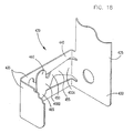
- a drive mounting screw receiving opening 360 is situated in main body 335 as shown in FIG. 12 and in the exploded perspective view of the drive 185, rail 190 and ground spring 330 assembly shown in FIG. 14.
- a pair of teeth or tangs 365 and 370 are situated adjacent opening 360 such that when ground spring 330 is mounted on rail 190 and screwed to metallic drive side surface 185A, tangs 365 and 370 dig into drive side surface 185A to form an electrical connection between grounding spring 330 and drive 185 as indicated in FIG. 14.
- Rail 190 is fabricated from electrically non-conductive material such as plastic materials.
- Rail 190 is a substantially flat strip including opposed ends 190A and 190B, and further includes opposed side surfaces 190C and 190D.
- Rail 190 includes as opening 375 appropriately shaped to receive side spring contact 350 therein when ground spring 330 is installed on rail 190.
- opening 375 may be rectangular in shape.
- Rail 190 includes an opening 380 which is appropriately shaped to receive flange 345 of wrap-around spring portion 340 when ground spring 330 is installed on rail 190.
- Rail 190 further includes a recessed portion 385 which wraps around rail end 190A from opening 380 on rail side surface 190C to opening 380 on opposite rail side surface 190D. Recessed portion 385 receives wrap-around spring portion 340 therein.
- Rail 190 further includes a screw hole 390 which aligns with opening 360 of ground spring 330 when ground spring 330 is mounted on rail 190. As shown in FIG. 14, rail 190 includes another screw hole 395 for facilitating mounting of rail 190 to drive 185.
- Drive 185 includes screw holes 400 and 405 which align with rail screw holes 390 and 395, respectively, when rail 190 is mounted on drive 185.
- flange 345 is pulled apart from main body 335 against spring action a sufficient distance to permit flange 345 to slide along the recessed portion 385 on rail side surface 190C until flange 345 engages opening 380 and wrap around portion 340 rests in recessed portion 385.
- spring contact 350 is placed in opening 375.
- a screw 410 is then inserted through hole 390, opening 360 and drive hole 400. Screw 410 is then turned until rail 190/spring 330 is held tightly to drive 185.
- a screw 415 is inserted through hole 395 and threaded into drive hole 405 and is similarly tightened.
- FIG. 15 is a bottom cross sectional view of ground spring 330 installed on a rail 190 which is mounted on drive 185, such drive 185 being installed in non-conductive drive support structure 20 within housing 15.
- the cross section shown in FIG. 15 is taken along section line D-D of FIG. 7 and additionally shows a portion of an electrically conductive drive retainer 420 in contact with ground spring 330 and housing 15. In this manner drive 185 is electrically connected to case 15 to establish a ground for drive 185.
- ground spring is usable in two different modes, first as a way to provide a connection between drive 185 and case 15 via wrap around portion 340 when a non-conductive drive support structure such as structure 20 is used to house a drive 185, and alternatively as a way to provide a connection between drive 185 and a conductive drive support structure (not shown) via spring contact 350 which would contact such a conductive drive support structure if used in place of support structure 20.
- Retainer 420 is discussed later in more detail.
- FIG. 16 As shown partially in the cross sectional view of drive 185 and adjacent structures in FIG. 16, another ground spring 330/rail 190′assembly substantially symmetrical with respect to the ground spring 330/rail 190 assembly is installed on the remaining opposed side surface 185A in a manner similar to that described above.
- This cross sectional view of FIG. 16 is taken along section line E-E of FIG. 7 and additionally shows a portion of drive retainer 420.
- An electro-magnetic interference (EMI)/radio frequency interference (RFI) shielding spring structure 425 is situated between case 15 and drive support structure 20 and further contacts both conductive retainer 420 and wrap around portion 340. In this manner, drive 185 is coupled to grounded case 15 and retainer 420 is coupled to grounded case 15. The nature of this grounding arrangement is now discussed in more detail.
- EMI electro-magnetic interference
- RFID radio frequency interference
- FIG. 17 is a right side perspective view of shielding spring structure 425 which is fabricated from a flat strip 430 of electrically conductive material.
- a plurality of dual spring structures designated 425(C1), 425(C2), 425(D1), 425(D2) and 425(E) extend from one side of strip 430.
- the alpha-numeric designation appearing in parentheses in each of the preceding spring structure designations denotes the corresponding drive bay into which the spring structure is located as will be discussed later in more detail.
- Shielding spring structure 425 is fabricated from the same types of electrically conductive material as grounding spring 330 described earlier.
- Dual spring structures 425(C1), 425(C2), 425(D1), 425(D2) and 425(E) are substantially identical and thus only dual spring structure 425(C1) will be discussed now for purposes of example.
- Dual spring structure 425(C1) includes a first spring member 435 having a contact plate 440 which integrally extends from spring strip 430. Prior to installation of spring structure 425 in case 15 and prior to loading of spring structure 425, contact plate 440 is oriented at an angle of approximately 95 degrees with respect to spring strip 430. At the end of contact plate 440 most distant from spring strip 430, spring structure 425(C1) is bent at an angle of approximately 90 degrees back toward spring strip 430 as shown in FIG. 17 to form a flange 445 which is oriented substantially parallel to spring strip 430.
- a second spring member 450 is punched out of the portion of first spring member 435 which forms contact plate 440 as seen in FIG. 17 and as seen more clearly in the left side perspective view of spring shielding structure 425 shown in FIG. 18.
- Second spring member 450 includes a central spring arm 455 which extends from spring strip 430 as seen in FIG. 18.
- Spring arm 455 includes opposed ends 455A and 455B of which ends 455A joins spring strip 430.
- a pair of wing members 460 and 465 extend away from spring arm end 455B as illustrated in FIG. 18. Wing members 460 and 465 may contact plate 440 which acts as a stop against further travel of wing members 460/465 toward plate 440.
- Second spring member 455 deflects in the direction indicated by arrow 470 in FIG. 18 and arrow 475 in FIG. 17 when placed in contact with retainer 420 of FIG. 16 as discussed later.
- Shielding spring structure 425 is installed in position on drive support structure 20 as indicated in FIG. 1A with each of dual spring structures 425(C1), 425(C2), 425(D1), 425(D2) and 425(E) being inserted into a corresponding one of bays C1, C2, D1, D2 and E, respectively.
- Spring strip 430 of FIG. 17 includes a guide hole 480 through which a guide post 485 of FIG. 2 extends when spring strip 430 is mounted on drive support structure 20.
- Drive support structure 20 further includes guide posts 490 and 495 which are substantially similar to guide post 485.
- spring strip 430 of shielding spring structure 425 further includes holes 500, 505 and 510 which are aligned with corresponding holes in drive support structure 20 when shielding spring structure 425 is mounted thereon. Screws (not shown) are screwed through these shielding spring holes 500, 505 and 510 and into the corresponding holes in drive support structure 20 to hold shielding spring structure 425 to drive support structure 20.
- Retainer 420 is fabricated from electrically conductive material and is generally rectangularly framelike in appearance. Retainer 420 includes substantially parallel side support members 515 and 520 which are joined at their respective tops by a connecting member 525. Support members 515 and 520 are joined at their respective bottom portions by a connecting member 530 which is appropriately dimensioned to cover drive C.
- Retainer 420 includes contact tabs 535(C1), 535(C2), 535(D1), 535(D1) and 535(E) which respectively contact second spring members 450 of spring structures 425(C1), 425(C2), 425(D1), 425(D1) and 425(E) of FIG. 17 when spring shield 425 and retainer 420 are installed on drive support structure 20. Although not visible in the view of retainer 420 shown in FIG.
- contact tabs 540(C1), 540(C2),540(D1), 540(D1) and 540(E) are situated on side support member 520 in symmetrical fashion about axis 545 with respect to contact tabs 535(C1), 535(C2),535(D1), 535(D1) and 535(E) which are shown on side support member 515.
- Contact tabs 540(C1), 540(C2),540(D1), 540(D1) and 540(E) are shown in the right side perspective view of retainer 420 of FIG. 19B.
- shielding spring 425 connects case 15 to both drive retainer 420 and full height drive 185.
- the arrangement shown in FIG. 16 results in three electrical contact zones 550, 555 and 560. More specifically, since spring strip 425 of shield spring 420 is sandwiched between drive support structure 20 and housing 15, housing 15 is thus connected to shield spring 425 at contact zone 550. Since connecting tab 535 of retainer 420 is electrically connected to second spring member 450 of shield spring 425 at contact zone 555, retainer 420 is thus grounded to case 15. Moreover, since wrap-around portion 340 of grounding spring 330 is connected to first spring member 435 at contact zone 560, drive 185 is thus grounded to case 15.
- a drive 195 mounted in adapter tray 200 with integral conductive side rails 200/205 is installed in drive support structure 20 in place of the drive 185 discussed above.
- the electrical grounding connections are made as follows.
- Retainer 420 is connected to housing 15 via contact zones 550 and 555 in the same manner as in FIG. 16 discussed above.
- conductive integral side rail 205 of adapter tray 200 is connected to first spring member 435 at contact zone 565.
- adapter tray 200 and drive 195 therein are grounded to case 15.
- electrically conductive bezels 570, 571, 572, 573 and 574 are mounted in retainer 420 respectively at bays D1, D2, E, B and A, respectively, if no drives are contained therein.
- drive support structure 20 includes snap members 580 and 585. Snap members 580 and 585 are used to initially hold retainer 420 to housing 15 before bezel 575 is attached to and mounted on retainer 420/housing 15 as will be discussed later in more detail.
- FIG. 22 a cross sectional view of a portion of drive support structure 20 of FIG. 2 taken along section line B-B is shown in FIG. 22. Snap member 585 is thus depicted in FIG. 22. A portion of housing 15 is shown adjacent drive support structure 20 in FIG. 22. Snap member 585 is substantially J-shaped and includes an end 585A which is integrally attached to drive support structure 20 as shown. Snap member 585 further includes an end 585B which extends through an opening 590 in drive support 20 and housing 15. Drive support structure 20 includes a similar opening 595 adjacent snap member 580 as shown in FIG. 2.
- snap member 585 includes a ramp-like guide 600 which deflects downward about curved portion 585C when member 580 engages retainer 420.
- a recessed portion or catch 605 is located at the upper end of ramp 600, the operation of which will be discussed later in more detail.
- Snap member 580 is substantially similar to snap member 585.
- retainer 420 includes holes, openings or slots 610 and 615 in side members 515 and 520 which are aligned with corresponding holes 595 and 590, respectively, in drive support structure 420 when retainer 420 is installed on case 15 and drive support structure 20.
- FIG. 23 shows a cross section of housing 15/drive support structure 20 of FIG. 1B taken along section line A-A together with a corresponding cross section of retainer 420.
- inset view 23A which is a magnified view of the lower portion of retainer 420 that is first installed in the base of housing 15, it is seen that the lowermost portion of retainer connecting member 530 includes a plurality of tabs 620, one of which is shown in FIG. 23 inset 23A. Four of such tabs 620 are shown in the perspective view of retainer 420 in FIG. 21.
- retainer 420 To install retainer 420, tabs 620 of retainer 420 are placed above and adjacent a lip member 625 in the base of case 15 as seen in FIG. 23 inset 23A. Lip member 625 is also shown in the view of enclosure 15 shown in FIG. 1B. Retainer 420 is then lifted slightly upward in the direction of arrow 630 and is rotated in the direction of arrow 635 about the pivot point 640 formed where tabs 620 contact member 625 of housing 15. Retainer 420 is rotated in the direction of arrow 635 until retainer 420 comes into contact with guide posts 485 and 490 as indicated in the cross sectional view of FIG. 24 and inset 24. Guide posts 485 and 490 are seen more clearly in the perspective view of drive support structure 20 of FIG. 2. As indicated in FIG.
- guide posts 485 and 490 extend beyond housing 15 through respective holes (not shown in detail) in housing 15 toward retainer 420.
- Guide post 485 includes a tapered end 485A as seen in FIG. 24 which is now discussed.
- Guide post 490 similarly includes a such a tapered end.
- FIG. 24 is the same cross sectional view as FIG. 23 except that further progress in the rotation of retainer 420 is shown in FIG. 24 and inset views 24A and 24B.
- retainer 420 includes holes 645 and 650 (shown in dashed lines) for engaging guide posts 485 and 490, respectively.
- hole 645 engages the tapered end 485A of guide post 485 as indicated in inset view 24B
- hole 645 rides up on the tapered end 485A to lift retainer 420 up in the direction of arrow 655.
- the same dynamics occur as retainer hole 650 engages guide post 490.
- Retainer 420 is thus appropriately positioned and aligned on housing 15.
- FIG. 25 is the same cross sectional view as FIG. 24 except that completion of progress in the rotation of retainer 420 is shown in FIG. 25 and inset views 25A, 25B and 25C thereof.
- the upper portion of the case 15/drive support structure 20 assembly includes a guide post 495 which is shown in more detail in inset view 25A and which was shown earlier in FIG. 2.
- guide post 495 passes through a hole or opening 665 (also see FIG. 21) in the upper portion of retainer 420.
- retainer opening 645 has fully engaged guide post 485.
- Guidepost 490 (see FIG. 2) is similarly engaged by retainer opening 650 (not shown in FIG. 25, but shown in dashed lines in FIG. 21 and shown in more detail in FIG. 19B. In this manner, the alignment of retainer 420 on the housing 15/support structure 20 assembly is completed.
- FIG. 25 inset 25C shows the orientation of tabs 620 of retainer 420 with respect to lip member 625 of housing 15 when installation of retainer 420 is complete.
- retainer opening 610 engages ramp 600 of snap member 580 causing ramp 600 to be deflected downward in the direction of arrow 660.
- opening 610 passes over ramp 600 and snap member 580 pops back up or snaps back up in the direction of arrow 670.
- latch 605 becomes latched to retainer 420 adjacent opening 610.
- snap member 580 is substantially similar to snap member 585 shown in FIG. 22 and that like numbers are used to indicate identical components of snap members 580 and 585.
- snap members 580 and 585 act as "living snaps" in that once opening 610 passes by latch 605, snap member 580 snaps back to its original undeflected position of its own accord.
- Snap member 585 shown in FIG. 2 operates in a manner substantially similar to that described above to engage a respective retainer opening 615 which is partially visible in FIG. 21 and which is shown in more detail in FIG. 19B.
- retainer 420 When installation of retainer 420 is complete on the housing 15/support structure 20 assembly, the disk drives which are installed in bays C1, C2, D1, D2 and E are held fixedly in position in these bays by retainer contact tabs 535(C1), 535(C2), 535(D1), 535(D1) and 535(E) which act as respective stops against movement by the respective drives at the left sides thereof.
- retainer contact tabs 535(C1), 535(C2), 535(D1), 535(D1) and 535(E) which act as respective stops against movement by the respective drives at the left sides thereof.
- FIG. 16 illustrate how one of such tabs 535 contacts wrap-around portion 340 of grounding spring 330 to prevent forward motion of rail 190′ and drive 185 attached thereto.
- retainer contact tabs 540(C1), 540(C2), 540(D1), 540(D1) and 540(E) provide a similar stopping action to the right side of the drives in bays C1, C2, D1, D2 and E as seen in FIG. 15.
- housing 15 includes a flange 675 which extends from top member 15C to bottom member 15D at the rightmost portion of housing 15.
- An electrically conductive grounding strip 680 is situated on flange 675.
- Grounding strip 680 is coextensive with flange 675 and is formed such that when retainer 420 is installed on the housing 15/drive support structure 20 assembly, the right side of retainer 420 is electrically coupled to housing 15 via conductive grounding strip 680.
- the structure and operation of grounding strip 680 is discussed in more detail in the copending patent application entitled “Self Contained Grounding Strip", by Cooke et al., Attorney Docket No. BC9-89-034, filed (filing date to be assigned), Serial No. (to be assigned), assigned to the instant assignee, such application being incorporated herein by reference.
- Bezel 575 includes side members 575A and 575B, top and bottom members 575C and 575D, and front and back surfaces 575E and 575F, respectively.
- Bezel 575 includes projections 695 and 700 extending from the uppermost portion of the rear of bezel 575.
- Bezel 575 further includes guide posts 705 and 710.
- Bezel 575 also includes resilient snap members 715 and 720 extending from the rear thereof.
- FIG. 27 is a side view of housing 25/drive support structure 20 which shows the initial positioning of retainer 420 prior to installation and which further shows the positioning of bezel 575 prior to installation. It is noted that retainer 420 pivots about the bottom of housing 15 whereas bezel 575 pivots about the top of housing 15. However, retainer 420 is installed prior to the installation of bezel 575.
- retainer 420 includes cams or rounded raised regions 685 and 690 on the upper portions of side members 515 and 520, respectively.
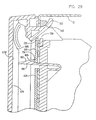
- FIG. 28 shows a cross sectional side view of a portion of bezel 575, retainer 420 and housing 15 taken along section line C-C of FIG. 19A.
- FIG. 28 will be used to illustrate the initial stage of installation of bezel 575 on retainer 420.
- projection 700 is inserted in an opening 725 of retainer 420 and through an opening 730 of housing 15, such openings 725 and 730 being shown in perspective in FIG. 19A.
- FIG. 19A also shows retainer opening 735 and housing opening 740 which by receiving projection 695 of bezel 575 perform a similar function to openings 725 and 730, respectively.
- outward force is still being exerted on latch 605 of snap member 580 in the direction of arrow 740 in FIG. 28.
- Bezel 575 has not yet relieved that pressure or force as indicated by latch 605 of snap member 580 still being in contact with retainer 420.
- Bezel 575 is now rotated about a pivot point 743 in the direction of arrow 745 toward retainer 420 until rear surface 575F of bezel 575 engages cam 685.
- rear bezel surface 575F continues to engage cam 685 so as to push retainer 420 inward in the direction of arrow 750 toward housing 15.
- this action causes retainer 420 to be pushed away from latch 605 as indicated by the space 755 between latch 605 and retainer 420. In this manner, the force which was earlier placed on latch 600 by retainer 420 is relieved.
- FIG. 30 is a cross sectional view of the lowermost portion of the bezel 575/retainer 420/housing 15/support structure 20 assembly of FIG. 19A along section line C-C.
- snap member 720 passes through an opening 760 in retainer 420 and through an opening 765 in housing 15 so as to latch with a lip 770 adjacent the bottom of housing 15. The location of lip 770 is shown in FIG. 19A.
- snap member 715 latches to a corresponding lip 775 (shown in FIG. 19A) after passing through corresponding openings in retainer 420 and housing 15 (not shown) which are adjacent to snap member 715 when bezel 575 is fully installed.
- guide post 710 (shown in FIG. 26) passes through opening 780 in retainer 420 (shown in FIG. 19A) and though opening 785 in housing 15 (also shown in FIG. 19A).
- Guide post 705 passes through similar openings in retainer 420 and housing 15.
- Guide posts 705 and 710 aid in the alignment of bezel 575 while bezel 575 is rotated and installed on retainer 420 as described above.
- the foregoing describes a grounding apparatus which grounds disk drives and a removable cover structure to a computer housing in such a fashion as to reduce undesired EMI and to yet permit ready removal of disk drives from the computer.
- a shielding strip for a computer including an electrically conductive housing and a non-conductive drive mounting structure situated within the housing.
- the drive mounting structure includes a plurality of bays which communicate with an opening in the housing.
- An electrically conductive retainer is situated over the opening to hold the disk drives in the bays.
- the shielding strip includes a longitudinal main portion extending along a first side of the housing adjacent the opening and situated between the first side of the housing and the drive mounting structure.
- the shielding strip further includes a plurality of spring structures extending laterally away from the main portion and toward the bays, each of such spring structures including a first spring portion for contacting the retainer and a second spring portion for contacting a conductive portion of a disk drive mounted in a respective bay.
Abstract
Description
- This invention relates in general to apparatus for reducing the emission of electromagnetic interference (EMI) and, more particularly, to a shielding strip for reducing EMI from computers.
- One way to substantially reduce unwanted electromagnetic radiations from a personal computer is to enclose the computer in a housing with no open ports or removable covers. This, of course, is unrealistic since thus user require access to such panel-mounted devices as disk drives, optical drives, and so forth. The user also requires access occasionally to the interior of the computer which necessitates some form of removable cover. Such a removable cover introduces the possibility of EMI radiations if appropriate design precautions are not taken.
- A computer housing is described herein which is capable of accommodating several disk drives or similar devices in a plurality of bays within the housing. A removable drive retainer/cover structure covers the disk drives. The housing is fabricated such that the drives are readily removable.
- Therefore, in accordance with the present invention there is provided a shielding strip for a computer including an electrically conductive housing and a non-conductive drive mounting structure situated within said housing, said drive mounting structure including a plurality of bays which communicate with an opening in said housing, a electrically conductive retainer being situated over said opening to hold said disk drives in said bays, said strip comprising:
a longitudinal main portion extending along a first side of said housing adjacent said opening and situated between the first side of said housing and said drive mounting structure, and
a plurality of spring structures extending laterally away from said main portion and toward said bays, each of said spring structures including a first spring portion for contacting said retainer and a second spring portion for contacting a conductive portion of a disk drive mounted in a respective bay. - The invention enables a grounding apparatus to be provided which grounds the disk drives and the removable cover structure to the housing in such a fashion as to reduce undesired EMS and to yet permit ready removal of disk drives from the computer.
- The invention further enables an enclosure for a computer to be provided, said enclosure comprising:
an electrically conductive case and a non-conductive mounting structure situated within said case, said mounting structure including means defining a plurality of bays for receiving devices,
a retainer removably connectable to said case to hold devices within said bays,
a shielding strip and grounding strap, for providing a conductive path for a device mounted in a respective bay,
the main body portion of the shielding strip extending longitudinally along a first side of the case, being in intimate conductive contact therewith, and located intermediate the first side of the case and the mounting structure. - The invention may best be understood by referring to the following description and accompanying drawings.
- FIG. 1A is an exploded perspective view of the computer housing, retainer and grounding strip;
- FIG. 1B is a perspective view of the computer housing including a drive support structure therein;
- FIG. 2 is a front right side perspective view of the drive support structure;
- FIG. 3 is a rear perspective view of the drive support structure;
- FIG. 4 is a front left side perspective view of the drive support structure;
- FIG. 5 is a perspective view of a drive support structure bay showing removable guides;
- FIG. 6 is an exploded perspective view showing a plurality of disk drive configurations which may be installed in the drive support structure;
- FIG. 7 is a front view of a full height drive installed in the drive support structure;
- FIG. 8 is a front view of two first size half height drives fitted with adapter trays and installed in the drive support structure;
- FIG. 9 is a front view of two second size half height drives fitted with adapter trays and installed in the drive support structure;
- FIG. 10 is a front view of the drive support structure;
- FIG. 11 is an exploded perspective view of a drive installed on the adapter tray;
- FIG. 12 is a perspective view of the ground spring for a rail mounted device;
- FIG. 13 is an exploded view of a rail mounted device employing the ground spring of FIG. 12 prior to installation of the device in the drive support structure;
- FIG. 14 is an exploded perspective view of the ground spring, rail and rail mounted device;
- FIG. 15 is a bottom cross sectional view of the ground spring installed on a rail mounted on a drive, such cross section being taken along section line D-D of FIG. 7;
- FIG. 16 is a bottom cross sectional view of the ground strip installed between the housing and drive support structure, such cross section being taken along section line E-E of FIG. 7 and showing the ground strip and surrounding components;
- FIG. 17 is a front perspective view of the ground strip of FIG. 16;
- FIG. 18 is a rear perspective view of the ground strip of FIG. 16;
- FIG. 19A is a front right side exploded perspective view showing the housing/drive support structure, the retainer and bezel;
- FIG. 19B is a rear left side perspective view of the retainer of FIG. 19A;
- FIG. 20 is the bottom cross sectional view showing the ground strip of FIG. 16 and surrounding components including an adapter tray mounted drive;
- FIG. 21 is a front right side perspective view of the retainer;
- FIG. 22 is a side cross sectional view which show a snap member of the drive support structure;
- FIG. 23 is a side cross sectional view of the computer housing/drive support assembly showing the initial stage of installation of the retainer on the assembly;
- FIG. 24 is a side cross sectional view of the computer housing/drive support assembly showing an intermediate stage of installation of the retainer on the assembly;
- FIG. 25 is a side cross sectional view of the computer housing/drive support assembly showing the final stage of installation of the retainer on the assembly wherein installation is complete;
- FIG. 26 is a rear perspective view of the bezel for the retainer;
- FIG. 27 is a side view of the computer housing showing the retainer and bezel prior to installation on the housing;
- FIG. 28 is a side cross sectional view showing the upper portion of the bezel during installation on the computer housing;
- FIG. 29 is a side cross sectional view showing the upper portion of the bezel after installation on the computer housing is complete;
- FIG. 30 is a side cross sectional view showing the lower portion of the bezel after installation on the computer housing is complete;
- FIG. 1A is an exploded perspective view of a
personal computer assembly 10 which includes an enclosure orcase 15 and a diskdrive support structure 20.Case 15 is fabricated from electrically conductive material and exhibits a generally parallelepiped shape. More specifically,case 15 includes front andback members bottom members 15C and 15D, and aside member 15E. The remaining sixth side of the parallelepiped geometry ofcase 15 is open as seen in FIG. 1A. Anopen chamber 25 is thus formed withincase 15 for receiving computer components and related structures such as diskdrive support structure 20. - When installed in
housing 15, as seen in FIG. 1B, diskdrive support structure 20 spans substantially the entire interior surface offront member 15A and a substantial portion of the interior ofcase 15.Support structure 20 is anchored at several locations withincase 15 and is configured to providecase 15 with additional structural integrity as will be discussed later in more detail. - Disk
drive support structure 20 is fabricated from electrically insulative, substantially structurally rigid material, such as polycarbonate/ABS plastic, for example. Diskdrive support structure 20 is illustrated in more detail in the front right side perspective view of FIG. 2. In the personal computer industry, the term "full height" disk drive is used to describe a particular size of disk drive and the term "half height" is used to describe a disk drive which exhibits a height which is approximately half the height of a "full height" disk drive. Both hard disk drives and floppy disk drives are available in either full height or half height versions. - Disk
drive support structure 20 includes a plurality of bays for housing a plurality of disk drives stacked one atop the other. More specifically,structure 20 includes bay C1 and bay C2 which together form a bay C. Bay C is capable of housing a single full height disk drive or two half height disk drives in bays C1 and C2, respectively.Structure 20 further includes a bay D which is substantially similar to bay C. Bay D includes bays D1 and D2. Bay D is capable of housing a single full height disk drive or two half height disk drives in bays D1 and D2, respectively. Diskdrive support structure 20 also includes a half height bay E as shown in FIG. 2 in this particular embodiment of the invention. Diskdrive support structure 20 still further includes bays A and B in the upper portion ofstructure 20 as shown in FIG. 2. - In more detail, disk
drive support structure 20 includes substantiallyparallel side walls Structure 20 further includes afront wall 40 which is integrally molded to and which extends betweenside walls structure 20 shown in FIG. 3. Returning again to FIG. 2, it is seen thatfront wall 40 ofstructure 20 includes a plurality ofopenings parallel shelves side walls structure 20.Shelf 20F is the topmost shelf ofshelves 20A-20F.Shelves - The periphery of
front wall 40 includes a plurality of bolt holes 60 to enable diskdrive support structure 20 to be securely bolted to the interior ofcase 15 as will now be described. As seen in FIG. 1B,front member 15A ofcase 15 includes a plurality ofbolt receiving holes 65 which are aligned with corresponding bolt holes 60 instructure 20 whenstructure 20 is situated withincase 15.Bolts 70 are then located in respective hole pairs 60-65 and fixed with appropriated fasteners to holdfront wall 40 ofstructure 20 firmly tofront member 15A ofhousing 15, - Returning again to FIG. 3, it is seen that disk
drive support structure 20 includes four mountingpads 70, each including arespective hole 75. Whenstructure 20 is situated in the interior ofcase 15 as in FIG. 1B, holes 75 ofstructure 20 align with corresponding respective threadedholes 80 inside member 15E. To increase clarity, a portion ofside member 15E adjacent arepresentative hole 80 is shown in FIG. 3 at approximately four times actual size. - A left side perspective view of
structure 20 is shown in FIG. 4 to more clearly depict mountingpads 70, holes 75 andside wall 35 of diskdrive support structure 20. Respective threadedbolts 85 are screwed through each of hole pairs 75-80 to securely holdside wall 35 ofstructure 20 toside member 15E ofcase 15. - As seen in FIG. 1B, drive
support structure 20 extends across the majority of the interior surface offront member 15A both laterally and longitudinally. In this particular embodiment,support structure 20 extends along the entirety of the interior surface offront member 15A. Moreover,support structure 20 is fixedly or rigidly attached to two substantially perpendicular members ofcase 15, namelyfront member 15A andside member 15E, as describe above. - When disk
drive support structure 20 is mounted withincase 15 in this manner, the structural integrity ofcase 15 is substantially increased.Support structure 20 houses and supports multiple disk drives while simultaneously improving the substantial structural integrity ofcase 15. More specifically, the multi-chamber nature ofstructure 20 acts to reinforcecase 15 and enhances the rigidity ofcase 15 against moments of force which would otherwise causecase 15 to undesirably twist and deform. - FIG. 5 is an enlarged and exploded right side perspective view of the lower bay C portion of disk
drive support structure 20, the entirety of which was shown earlier in FIG. 2. Bay D is substantially identical to bay C and thus the following discussion of bay C will apply to bay D as well. Half height drives or full height drives generally have respective plastic rails mounted to the two opposed side surfaces thereof to permit such drives to slide in and out of fixed, non-removable rail guides which are typically situated within a computer. It is desirable to have maximum flexibility in the choice of placement of one full height or two half height drives in bays C and D. Moreover, it is desirable to provide a reasonable amount of clearance or sway space between the sides of a hard disk mounted in a bay to avoid or reduce shock damage to such hard drives. - Bay C is provided with removable drive support guides 90 as shown in FIG. 5. The upper portion of bay C includes support
guide receiving channels side walls removable support guide 90 therein as will be discussed subsequently in more detail. The lower portion of bay C includes rail receiving guides 100A and 100B which are integrally formed intoside walls guides guide receiving channels guides - In this particular embodiment, support guides 90 are substantially rectangular in shape and include opposed ends 105 and 100, and further include
opposed sides Guide receiving channels slots side walls -
Slot 125 includes opposed ends 125A and 125B.Slot 130 includes opposed ends 130A and 130B. Support guides 90 include flexible snaps or latches 135 and 140 which are spaced apart by a predetermined distance approximately equal to the length ofslots support guide 90 inslot 130 will now be discussed although it should be appreciated that asupport guide 90 can be situated inslot 125 as well using the same technique. A pair ofstops 145 and 150 are situatedadjacent latch 135 as shown in FIG. 5. Similarly, a pair ofstops adjacent latch 140. When support guide 90 is placed in position inchannel 95B, stop pair 145-150 is situated adjacent slot end 130A and stop pair 155-160 is situatedadjacent slot end 130B so as to prevent substantial lateral movement ofsupport guide 90 withinchannel 95B. -
Latch 135 includes aflexible arm 135A extending fromguide 90. A catch orprotrusion 135B is situated at the end ofarm 135A such that as stop pair 145-150 ofguide 90 is placed inslot 130,arm 135A deflects untilprotrusion 135B catches and holds to slotend 130A. In a similar manner,latch 140 includes aflexible arm 140A extending fromguide 90 and a catch orprotrusion 140B at the end ofarm 140.Arm 140B similarly deflects when stop pair 155-160 ofguide 90 is placed inslot 130.Protrusion 140B then catches onend 130B to holdguide 90 in position inslot 130 ofchannel 95B. From the above, it will be appreciated that latches 135 and 140 are living snap members which are integrally formed intoguide 90.Support guide 90 is easily removed fromchannel 95B by pullingguide 90 away fromslot 130 with sufficient force to deflectarms latches -
Side 115 ofguide 90 includes achannel 165 for receiving a disk drive rail or other sliding structure. When drive support guides 90 are removably mounted inchannels channels 165 of support guides 90. - To facilitate the sliding of a rail into
channel 165 ofsupport guide 90, guide 90 includes a pair ofprotrusions channel 165 as the rail initially approaches and engageschannel 165. - FIG. 6 is an exploded perspective view of the front portion of
personal computer assembly 10 which demonstrates the different drive combinations which drivesupport structure 20 is capable of housing. To promote clarity, the lower portion of drive C is designated bay C1 and the upper portion of bay C is designated bay C2. In a like manner, the lower portion of drive D is designated bay D1 and the upper portion of bay D is designated bay D2. - At this particular stage in disk drive technology, most disk drives exhibit one of two different standard heights (full height or half height) and one of two different standard widths (5.25 inch or 3.5 inch). Disk
drive support structure 20 supports all of these types of drives as seen in the examples portrayed in FIG. 6. While bays C and D ofstructure 20 are full height bays, bays C1, C2, D1 and D2 are half height bays. - To accommodate a
full height drive 185 in bay C, snap-in support guides 90 are removed fromchannels drive 185, are slid into receivingguides - To accommodate two half height 3.5 inch drives 195 in bay of snap-in support guides 90 are installed in
channels drives 195 is installed in anadapter tray 200 which includes integral conductive side rails 205 and 210 as will be discussed later in detail. In lower bay C1, side rails 205 and 210 slide into receivingguides respective channels 165 of support guides 90. - To accommodate two half height 5.25 inch drives 215 in bay C, snap-in support guides 90 are installed in
channels rails 220 is attached to the respective opposite sides ofdrives 215, only onerail 220 of which is visible on each drive 215 of FIG. 6. As seen in the front plan view of bay C in FIG. 9, in lower bay C1, rails 220 ofdrive 215 slide into receivingguides drive 215 slide intorespective channels 165 of support guides 90. - Returning again to FIG. 6, it is noted that bay D is substantially similar to bay C. Thus, bay D can likewise accommodate a full
height disk drive 185, two half height disk drives 215 or two adapter tray-mounteddisk drives 195 in a manner similar to bay C. - As indicated in FIG. 6, bay E can accommodate either a single half height drive 230 which is similar to drive 215 or alternatively accommodate a single adapter tray-mounted half height drive 235 which is similar to drive 195. The rails on either drive 230 or drive 235 are situated in respective rail receiving guides 225A and 225B (depicted in FIG. 10) which are substantially similar to rail receiving guides 100A and 100B of bays C and D.
- As indicated in FIG. 6, each of bays A and B are capable of receiving a
disk drive 245. As shown in FIG. 10, a pair of disk drive mounts 250 and 255 are situated onshelf 20A of bay A. Mounts 250 and 255 are inverted L structures facing opposite directions.Mounts arm portions disk drive 245 are slid into the region formed betweenarm 250A andshelf 20A, and the region formed betweenarm 255A andshelf 20A, respectively, to hold drive 245 toshelf 20A in bay A. - Bay B also includes disk drive mounts 250 and 255 on
shelf 20B thereof.Mounts disk drive 245 toshelf 20B in the same manner described above. Other electrical equipment, such as switches, keylocks, displays and indicator lights, for example, or other devices may be installed in the region aboveshelf 20F and betweenside walls - Although in the discussion of disk
drive support structure 20 above, the mounting and housing of full height, half height, 5.25 inch and 3.5 inch disk drives have been discussed, those skilled in the art will appreciate that the present invention is not limited to these particular heights and sizes. Rather, the dimensions ofstructure 20 may be readily modified to accommodate disk drives of other sizes as well. Moreover, although in the above description,support structure 20 has been referred to as a disk drive support structure,structure 20 can support and house other electrical devices as well, for example, tape drives, removable hard disks, optical drives and the like. - FIG. 11 is a front right side perspective view of the disk
drive adapter tray 200 which was mentioned earlier in the discussion of FIG. 8.Tray 200 is used to adapt a disk drive or other device which is substantially narrower than bays C, D or E to fit in such bays. As discussed earlier, bays C, D and E are sufficiently wide to accommodate 5.25 inch media therein.Adapter tray 200 permits a narrower media device such as a 3.5 inch drive to be installed between rail receivingguide pairs 100A/ 100B and 225A/225B or between support guides installed inchannels 95A/95B, these locations being shown in FIG. 8 and FIG. 10. - Returning again to FIG. 11, it is seen that
adapter tray 200 exhibits a substantially rectangular framelike shape.Tray 200 is fabricated from electrically conductive material.Adapter tray 200 includesside members flat base Base 270 includes opposed ends 270A and 270B.Base 275 includes opposed ends 275A and 275B. A connectingbar 280 is integrally formed from the same material asside members bar 280 extends between ends 270A and 275A ofbases bar 280 is bent downward to form an angle of approximately 90 degrees with respect to the plane ofbases bar 285 joins ends 270B and 275B ofbases bar 285 is formed integrally from the same material asbases - A
drive carriage member 290 is joined tobase 260 viaarms Carriage member 290 extends downwardly frombase 270 as shown in FIG. 11. Another drive carriage member 305 (partially shown in FIG. 11) which is substantially similar tocarriage member 290 extends downwardly frombase 275.Carriage members holes 310 which align withcorresponding holes 315 indisk drive 195 whendrive 195 is situated betweencarriage members holes 310 andholes 315 to holddrive 195 in position withinadapter tray 200 thus forming an electrical connection betweendrive 195 andadapter tray 200. -
Adapter tray 200 includes side rails 320 and 325 which are integrally formed intobases bases Side rail 320 includes opposed ends 320A and 320B.Side rail 325 includes opposed ends 325A and 325B. As seen in FIG. 11, side rails 320 and 325 are bent upwardly with respect tobases bases - Connecting
member 280 acts as a convenient handle for the user to grasp when installingadapter tray 200 within a disk drive bay. To actually placeadapter tray 200/drive 195 in a disk drive bay such as bay C1, for example, the user grasps connecting member (handle) 280 and slides side rails 320 and 325 into rail receiving guides 100A and 100B, respectively. Side rails 320 and 325 are spaced apart by a predetermined distance selected such thatrails - FIG. 12 is a back side perspective view of a
ground spring 330 which is mountable on aremovable side rail 190 of FIG. 6 (or 220 of FIG. 6) to permit grounding of adrive 185 of FIG. 7 (or drive 215 of FIG. 9) when such drive is mounted in the non-conductivedrive support structure 20 of FIG. 1A. FIG. 13 is provided to illustrate the spatial relationship ofground spring 330,removable side rail 190 and drive 185. - Returning again to FIG. 12,
ground spring 330 includes a flat main body orshank 335 having opposed back andfront surfaces Ground spring 330 is fabricated from relatively thin electrically conductive material such as stainless steel, although other conductive materials such as beryllium copper, phosphor bronze, or high tensile strength spring steel may be employed. As seen in FIG. 12,ground spring 330 includes a wrap-aroundspring portion 340 integrally formed at springmain body end 335C. Wrap-aroundspring portion 340 includes aflange 345 which tapers inwardly towardmain body 335. - A
side spring contact 350 is integrally formed at the opposite main body end 335D.Side spring contact 350 is a flange which slopes away from springmain body 335 atflange portion 350A and then bends back towardmain body 335 atflange portion 350B so as to form an apex 355 betweenflange portions drive support structure 20 described herein. - A drive mounting
screw receiving opening 360 is situated inmain body 335 as shown in FIG. 12 and in the exploded perspective view of thedrive 185,rail 190 andground spring 330 assembly shown in FIG. 14. A pair of teeth ortangs 365 and 370 (see FIG. 12) are situatedadjacent opening 360 such that whenground spring 330 is mounted onrail 190 and screwed to metallicdrive side surface 185A,tangs drive side surface 185A to form an electrical connection betweengrounding spring 330 and drive 185 as indicated in FIG. 14. - To enable a better appreciation of the operation of
ground spring 330 which is mountable inremovable rail 190,rail 190 is now described in more detail using the exploded perspective view of FIG. 14.Rail 190 is fabricated from electrically non-conductive material such as plastic materials.Rail 190 is a substantially flat strip including opposed ends 190A and 190B, and further includes opposed side surfaces 190C and 190D.Rail 190 includes as opening 375 appropriately shaped to receiveside spring contact 350 therein whenground spring 330 is installed onrail 190. For example, opening 375 may be rectangular in shape.Rail 190 includes anopening 380 which is appropriately shaped to receiveflange 345 of wrap-aroundspring portion 340 whenground spring 330 is installed onrail 190.Rail 190 further includes a recessedportion 385 which wraps aroundrail end 190A from opening 380 onrail side surface 190C to opening 380 on oppositerail side surface 190D. Recessedportion 385 receives wrap-aroundspring portion 340 therein. -
Rail 190 further includes ascrew hole 390 which aligns with opening 360 ofground spring 330 whenground spring 330 is mounted onrail 190. As shown in FIG. 14,rail 190 includes anotherscrew hole 395 for facilitating mounting ofrail 190 to drive 185. Drive 185 includes screw holes 400 and 405 which align with rail screw holes 390 and 395, respectively, whenrail 190 is mounted ondrive 185. - To actually mount
ground spring 330 onrail 190,flange 345 is pulled apart frommain body 335 against spring action a sufficient distance to permitflange 345 to slide along the recessedportion 385 onrail side surface 190C untilflange 345 engages opening 380 and wrap aroundportion 340 rests in recessedportion 385. At substantially the same time,spring contact 350 is placed inopening 375. Ascrew 410 is then inserted throughhole 390, opening 360 and drivehole 400.Screw 410 is then turned untilrail 190/spring 330 is held tightly to drive 185. Ascrew 415 is inserted throughhole 395 and threaded intodrive hole 405 and is similarly tightened. - FIG. 15 is a bottom cross sectional view of
ground spring 330 installed on arail 190 which is mounted ondrive 185,such drive 185 being installed in non-conductivedrive support structure 20 withinhousing 15. The cross section shown in FIG. 15 is taken along section line D-D of FIG. 7 and additionally shows a portion of an electricallyconductive drive retainer 420 in contact withground spring 330 andhousing 15. In this manner drive 185 is electrically connected tocase 15 to establish a ground fordrive 185. Thus ground spring is usable in two different modes, first as a way to provide a connection betweendrive 185 andcase 15 via wrap aroundportion 340 when a non-conductive drive support structure such asstructure 20 is used to house adrive 185, and alternatively as a way to provide a connection betweendrive 185 and a conductive drive support structure (not shown) viaspring contact 350 which would contact such a conductive drive support structure if used in place ofsupport structure 20.Retainer 420 is discussed later in more detail. - As shown partially in the cross sectional view of
drive 185 and adjacent structures in FIG. 16, anotherground spring 330/rail 190′assembly substantially symmetrical with respect to theground spring 330/rail 190 assembly is installed on the remainingopposed side surface 185A in a manner similar to that described above. This cross sectional view of FIG. 16 is taken along section line E-E of FIG. 7 and additionally shows a portion ofdrive retainer 420. An electro-magnetic interference (EMI)/radio frequency interference (RFI) shieldingspring structure 425 is situated betweencase 15 and drivesupport structure 20 and further contacts bothconductive retainer 420 and wrap aroundportion 340. In this manner, drive 185 is coupled to groundedcase 15 andretainer 420 is coupled to groundedcase 15. The nature of this grounding arrangement is now discussed in more detail. - FIG. 17 is a right side perspective view of shielding
spring structure 425 which is fabricated from aflat strip 430 of electrically conductive material. A plurality of dual spring structures designated 425(C1), 425(C2), 425(D1), 425(D2) and 425(E) extend from one side ofstrip 430. The alpha-numeric designation appearing in parentheses in each of the preceding spring structure designations denotes the corresponding drive bay into which the spring structure is located as will be discussed later in more detail. Shieldingspring structure 425 is fabricated from the same types of electrically conductive material as groundingspring 330 described earlier. Dual spring structures 425(C1), 425(C2), 425(D1), 425(D2) and 425(E) are substantially identical and thus only dual spring structure 425(C1) will be discussed now for purposes of example. - Dual spring structure 425(C1) includes a
first spring member 435 having acontact plate 440 which integrally extends fromspring strip 430. Prior to installation ofspring structure 425 incase 15 and prior to loading ofspring structure 425,contact plate 440 is oriented at an angle of approximately 95 degrees with respect tospring strip 430. At the end ofcontact plate 440 most distant fromspring strip 430, spring structure 425(C1) is bent at an angle of approximately 90 degrees back towardspring strip 430 as shown in FIG. 17 to form aflange 445 which is oriented substantially parallel tospring strip 430. - A
second spring member 450 is punched out of the portion offirst spring member 435 which formscontact plate 440 as seen in FIG. 17 and as seen more clearly in the left side perspective view ofspring shielding structure 425 shown in FIG. 18.Second spring member 450 includes acentral spring arm 455 which extends fromspring strip 430 as seen in FIG. 18. -
Spring arm 455 includes opposed ends 455A and 455B of which ends 455A joinsspring strip 430. A pair ofwing members spring arm end 455B as illustrated in FIG. 18.Wing members plate 440 which acts as a stop against further travel ofwing members 460/465 towardplate 440.Second spring member 455 deflects in the direction indicated byarrow 470 in FIG. 18 andarrow 475 in FIG. 17 when placed in contact withretainer 420 of FIG. 16 as discussed later. - Shielding
spring structure 425 is installed in position ondrive support structure 20 as indicated in FIG. 1A with each of dual spring structures 425(C1), 425(C2), 425(D1), 425(D2) and 425(E) being inserted into a corresponding one of bays C1, C2, D1, D2 and E, respectively.Spring strip 430 of FIG. 17 includes aguide hole 480 through which aguide post 485 of FIG. 2 extends whenspring strip 430 is mounted ondrive support structure 20. Drivesupport structure 20 further includes guide posts 490 and 495 which are substantially similar to guidepost 485. Returning again to FIG. 17, it is seen thatspring strip 430 of shieldingspring structure 425 further includesholes drive support structure 20 when shieldingspring structure 425 is mounted thereon. Screws (not shown) are screwed through these shielding spring holes 500, 505 and 510 and into the corresponding holes indrive support structure 20 to hold shieldingspring structure 425 to drivesupport structure 20. - Before completing the discussion of
spring shield 425, it is helpful to discussdrive retainer 420 which aids in holding any drives in place which are installed in bays C, D and E. Referring now to FIG. 19A,disk drive retainer 420 is shown in more detail.Retainer 420 is fabricated from electrically conductive material and is generally rectangularly framelike in appearance.Retainer 420 includes substantially parallelside support members member 525.Support members member 530 which is appropriately dimensioned to cover drive C. -
Retainer 420 includes contact tabs 535(C1), 535(C2), 535(D1), 535(D1) and 535(E) which respectively contactsecond spring members 450 of spring structures 425(C1), 425(C2), 425(D1), 425(D1) and 425(E) of FIG. 17 whenspring shield 425 andretainer 420 are installed ondrive support structure 20. Although not visible in the view ofretainer 420 shown in FIG. 19A, contact tabs 540(C1), 540(C2),540(D1), 540(D1) and 540(E) are situated onside support member 520 in symmetrical fashion aboutaxis 545 with respect to contact tabs 535(C1), 535(C2),535(D1), 535(D1) and 535(E) which are shown onside support member 515. Contact tabs 540(C1), 540(C2),540(D1), 540(D1) and 540(E) are shown in the right side perspective view ofretainer 420 of FIG. 19B. - The electrical connections achieved by shielding
spring 425 are now discussed with reference to FIG. 16 which depicts afull height drive 185 installed in a bay indrive support structure 20.Shielding spring 425 connectscase 15 to both driveretainer 420 andfull height drive 185. The arrangement shown in FIG. 16 results in threeelectrical contact zones spring strip 425 ofshield spring 420 is sandwiched betweendrive support structure 20 andhousing 15,housing 15 is thus connected to shieldspring 425 atcontact zone 550. Since connectingtab 535 ofretainer 420 is electrically connected tosecond spring member 450 ofshield spring 425 atcontact zone 555,retainer 420 is thus grounded tocase 15. Moreover, since wrap-aroundportion 340 ofgrounding spring 330 is connected tofirst spring member 435 atcontact zone 560, drive 185 is thus grounded tocase 15. - Alternatively, as shown in FIG. 20, a
drive 195 mounted inadapter tray 200 with integral conductive side rails 200/205 is installed indrive support structure 20 in place of thedrive 185 discussed above. In this instance, the electrical grounding connections are made as follows.Retainer 420 is connected tohousing 15 viacontact zones integral side rail 205 ofadapter tray 200 is connected tofirst spring member 435 atcontact zone 565. Thus,adapter tray 200 and drive 195 therein are grounded tocase 15. - As seen in FIG. 21, to further enhance shielding in
personal computer assembly 10, electricallyconductive bezels retainer 420 respectively at bays D1, D2, E, B and A, respectively, if no drives are contained therein. By employing the grounding and shielding structures described above with reference mainly to FIG.'s 16-21, both EMI and RFI emanations radiating from withincase 15 are significantly reduced. - Before discussing the manner in which
retainer 420 andbezel 575 of FIG. 19A cooperate to hold respective drives in bays C1, C2, D1, D2 and E, it is helpful to discussdrive support structure 20 andretainer 420 further. Referring to FIG. 2, it seen that drivesupport structure 20 includessnap members Snap members retainer 420 tohousing 15 beforebezel 575 is attached to and mounted onretainer 420/housing 15 as will be discussed later in more detail. - To more clearly show the shape of
snap members 580 and 585 a cross sectional view of a portion ofdrive support structure 20 of FIG. 2 taken along section line B-B is shown in FIG. 22.Snap member 585 is thus depicted in FIG. 22. A portion ofhousing 15 is shown adjacentdrive support structure 20 in FIG. 22.Snap member 585 is substantially J-shaped and includes anend 585A which is integrally attached to drivesupport structure 20 as shown.Snap member 585 further includes anend 585B which extends through anopening 590 indrive support 20 andhousing 15. Drivesupport structure 20 includes asimilar opening 595adjacent snap member 580 as shown in FIG. 2. Returning again to FIG. 22, it is seen thatsnap member 585 includes a ramp-like guide 600 which deflects downward aboutcurved portion 585C whenmember 580 engagesretainer 420. A recessed portion or catch 605 is located at the upper end oframp 600, the operation of which will be discussed later in more detail.Snap member 580 is substantially similar to snapmember 585. - Referring now to FIG. 21 and as shown more clearly in FIG. 19B,
retainer 420 includes holes, openings orslots side members holes drive support structure 420 whenretainer 420 is installed oncase 15 and drivesupport structure 20. - The installation of
retainer 420 oncase 15/drive support structure 20 is now discussed. FIG. 23 shows a cross section ofhousing 15/drive support structure 20 of FIG. 1B taken along section line A-A together with a corresponding cross section ofretainer 420. Referring now toinset view 23A, which is a magnified view of the lower portion ofretainer 420 that is first installed in the base ofhousing 15, it is seen that the lowermost portion ofretainer connecting member 530 includes a plurality oftabs 620, one of which is shown in FIG. 23inset 23A. Four ofsuch tabs 620 are shown in the perspective view ofretainer 420 in FIG. 21. - To install
retainer 420,tabs 620 ofretainer 420 are placed above and adjacent alip member 625 in the base ofcase 15 as seen in FIG. 23inset 23A.Lip member 625 is also shown in the view ofenclosure 15 shown in FIG. 1B.Retainer 420 is then lifted slightly upward in the direction ofarrow 630 and is rotated in the direction ofarrow 635 about thepivot point 640 formed wheretabs 620contact member 625 ofhousing 15.Retainer 420 is rotated in the direction ofarrow 635 untilretainer 420 comes into contact withguide posts drive support structure 20 of FIG. 2. As indicated in FIG. 24, guide posts 485 and 490 extend beyondhousing 15 through respective holes (not shown in detail) inhousing 15 towardretainer 420.Guide post 485 includes atapered end 485A as seen in FIG. 24 which is now discussed.Guide post 490 similarly includes a such a tapered end. - FIG. 24 is the same cross sectional view as FIG. 23 except that further progress in the rotation of
retainer 420 is shown in FIG. 24 and inset views 24A and 24B. As seen in FIG. 21,retainer 420 includesholes 645 and 650 (shown in dashed lines) for engagingguide posts retainer 420 continues such thathole 645 engages thetapered end 485A ofguide post 485 as indicated in inset view 24B,hole 645 rides up on thetapered end 485A to liftretainer 420 up in the direction ofarrow 655. The same dynamics occur asretainer hole 650 engagesguide post 490.Retainer 420 is thus appropriately positioned and aligned onhousing 15. - After
retainer 420 engages guide posts 485 and 490 in the above described manner, rotation ofretainer 420 in the direction indicated byarrow 635 of FIG. 24 is continued untilretainer 420 completely mates withhousing 15/drive support structure 20 as shown in FIG. 25. FIG. 25 is the same cross sectional view as FIG. 24 except that completion of progress in the rotation ofretainer 420 is shown in FIG. 25 and inset views 25A, 25B and 25C thereof. - As seen in FIG. 25, the upper portion of the
case 15/drive support structure 20 assembly includes aguide post 495 which is shown in more detail ininset view 25A and which was shown earlier in FIG. 2. When the pivotal rotation ofretainer 420 toward thehousing 15/drive support structure 20 assembly is nearly complete, guidepost 495 passes through a hole or opening 665 (also see FIG. 21) in the upper portion ofretainer 420. - Similarly, as seen in FIG. 25
inset view 25B, whenretainer 420 is fully installed on thehousing 15/support structure 20 assembly,retainer opening 645 has fully engagedguide post 485. Guidepost 490 (see FIG. 2) is similarly engaged by retainer opening 650 (not shown in FIG. 25, but shown in dashed lines in FIG. 21 and shown in more detail in FIG. 19B. In this manner, the alignment ofretainer 420 on thehousing 15/support structure 20 assembly is completed. - FIG. 25
inset 25C shows the orientation oftabs 620 ofretainer 420 with respect tolip member 625 ofhousing 15 when installation ofretainer 420 is complete. - As seen in FIG. 25, taken in conjunction with FIG. 22, when the rotation of the upper portion of
retainer 420 toward thehousing 15/support structure 20 assembly is nearly complete,retainer opening 610 engagesramp 600 ofsnap member 580 causingramp 600 to be deflected downward in the direction ofarrow 660. As rotation ofretainer 420 continues, opening 610 passes overramp 600 andsnap member 580 pops back up or snaps back up in the direction ofarrow 670. When this occurs,latch 605 becomes latched toretainer 420adjacent opening 610. It is noted thatsnap member 580 is substantially similar to snapmember 585 shown in FIG. 22 and that like numbers are used to indicate identical components ofsnap members snap members latch 605,snap member 580 snaps back to its original undeflected position of its own accord.Snap member 585 shown in FIG. 2 operates in a manner substantially similar to that described above to engage arespective retainer opening 615 which is partially visible in FIG. 21 and which is shown in more detail in FIG. 19B. - When installation of
retainer 420 is complete on thehousing 15/support structure 20 assembly, the disk drives which are installed in bays C1, C2, D1, D2 and E are held fixedly in position in these bays by retainer contact tabs 535(C1), 535(C2), 535(D1), 535(D1) and 535(E) which act as respective stops against movement by the respective drives at the left sides thereof. Reference is now made to FIG. 16 to illustrate how one ofsuch tabs 535 contacts wrap-aroundportion 340 ofgrounding spring 330 to prevent forward motion ofrail 190′ and drive 185 attached thereto. In addition to the stopping action provided by retainer contact tabs 535(C1), 535(C2), 535(D1), 535(D1) and 535(E) described above, retainer contact tabs 540(C1), 540(C2), 540(D1), 540(D1) and 540(E) (shown in detail in FIG. 19B) provide a similar stopping action to the right side of the drives in bays C1, C2, D1, D2 and E as seen in FIG. 15. - The arrangement for grounding the right side of
retainer 420 tocase 15 is now discussed. As seen in FIG. 1A,housing 15 includes a flange 675 which extends fromtop member 15C to bottom member 15D at the rightmost portion ofhousing 15. An electricallyconductive grounding strip 680 is situated on flange 675. Groundingstrip 680 is coextensive with flange 675 and is formed such that whenretainer 420 is installed on thehousing 15/drive support structure 20 assembly, the right side ofretainer 420 is electrically coupled tohousing 15 viaconductive grounding strip 680. The structure and operation ofgrounding strip 680 is discussed in more detail in the copending patent application entitled "Self Contained Grounding Strip", by Cooke et al., Attorney Docket No. BC9-89-034, filed (filing date to be assigned), Serial No. (to be assigned), assigned to the instant assignee, such application being incorporated herein by reference. - It is noted that prior to installation of
bezel 575 onretainer 420, a significant amount of force is exerted outwardly oncatches 605 ofsnap members retainer 420 holds such drives in their respective bays. The installation ofbezel 575 on the assembly formed byretainer 420,housing 15 and drivesupport structure 20 relieves this force and tension. Reference is now made to the front perspective view ofbezel 575 is shown in FIG. 19A.Bezel 575 includesside members bottom members 575C and 575D, and front andback surfaces - A rear perspective view of
bezel 575 is shown in FIG. 26.Bezel 575 includesprojections bezel 575.Bezel 575 further includes guide posts 705 and 710.Bezel 575 also includesresilient snap members - FIG. 27 is a side view of
housing 25/drive support structure 20 which shows the initial positioning ofretainer 420 prior to installation and which further shows the positioning ofbezel 575 prior to installation. It is noted thatretainer 420 pivots about the bottom ofhousing 15 whereasbezel 575 pivots about the top ofhousing 15. However,retainer 420 is installed prior to the installation ofbezel 575. - As seen in FIG. 19A and partially in FIG's 25 and 27,
retainer 420 includes cams or rounded raisedregions side members bezel 575,retainer 420 andhousing 15 taken along section line C-C of FIG. 19A. FIG. 28 will be used to illustrate the initial stage of installation ofbezel 575 onretainer 420. First,projection 700 is inserted in anopening 725 ofretainer 420 and through anopening 730 ofhousing 15,such openings retainer opening 735 andhousing opening 740 which by receivingprojection 695 ofbezel 575 perform a similar function toopenings bezel 575, outward force is still being exerted onlatch 605 ofsnap member 580 in the direction ofarrow 740 in FIG. 28.Bezel 575 has not yet relieved that pressure or force as indicated bylatch 605 ofsnap member 580 still being in contact withretainer 420. -
Bezel 575 is now rotated about apivot point 743 in the direction ofarrow 745 towardretainer 420 untilrear surface 575F ofbezel 575 engagescam 685. As the rotation ofbezel 575 is continued,rear bezel surface 575F continues to engagecam 685 so as to pushretainer 420 inward in the direction ofarrow 750 towardhousing 15. As the rotation ofbezel 575 is continued untilrear bezel surface 575F fully engagescam 685 as shown in FIG. 29, this action causesretainer 420 to be pushed away fromlatch 605 as indicated by thespace 755 betweenlatch 605 andretainer 420. In this manner, the force which was earlier placed onlatch 600 byretainer 420 is relieved. - FIG. 30 is a cross sectional view of the lowermost portion of the
bezel 575/retainer 420/housing 15/support structure 20 assembly of FIG. 19A along section line C-C. As seen in FIG. 30, whenbezel 575 is fully rotated into position onretainer 420 as described above,snap member 720 passes through anopening 760 inretainer 420 and through anopening 765 inhousing 15 so as to latch with alip 770 adjacent the bottom ofhousing 15. The location oflip 770 is shown in FIG. 19A. Similarly,snap member 715 latches to a corresponding lip 775 (shown in FIG. 19A) after passing through corresponding openings inretainer 420 and housing 15 (not shown) which are adjacent to snapmember 715 whenbezel 575 is fully installed. - As
bezel 575 is rotated and installed onretainer 420 as described above, guide post 710 (shown in FIG. 26) passes through opening 780 in retainer 420 (shown in FIG. 19A) and though opening 785 in housing 15 (also shown in FIG. 19A).Guide post 705 passes through similar openings inretainer 420 andhousing 15. Guide posts 705 and 710 aid in the alignment ofbezel 575 whilebezel 575 is rotated and installed onretainer 420 as described above. - The foregoing describes a grounding apparatus which grounds disk drives and a removable cover structure to a computer housing in such a fashion as to reduce undesired EMI and to yet permit ready removal of disk drives from the computer.
- There has been described a shielding strip for a computer including an electrically conductive housing and a non-conductive drive mounting structure situated within the housing. The drive mounting structure includes a plurality of bays which communicate with an opening in the housing. An electrically conductive retainer is situated over the opening to hold the disk drives in the bays. The shielding strip includes a longitudinal main portion extending along a first side of the housing adjacent the opening and situated between the first side of the housing and the drive mounting structure. The shielding strip further includes a plurality of spring structures extending laterally away from the main portion and toward the bays, each of such spring structures including a first spring portion for contacting the retainer and a second spring portion for contacting a conductive portion of a disk drive mounted in a respective bay.
Claims (3)
a longitudinal main portion extending along a first side of said housing adjacent said opening and situated between the first side of said housing and said drive mounting structure, and
a plurality of spring structures extending laterally away from said main portion and toward said bays, each of said spring structures including a first spring portion (450) for contacting said retainer and a second spring portion (440) for contacting a conductive portion of a disk drive mounted in a respective bay.
an electrically conductive case (15) and a non-conductive mounting structure (20) situated within said case (15), said mounting structure (20) including means defining a plurality of bays for receiving devices,
a retainer (420) removably connectable to said case to hold I/O devices within said bays,
a shielding strip (425) as claimed in claim 1 and grounding strap (330), for providing a conductive path for a device mounted in a respective bay,
the main body portion of the shielding strip (425) extending longitudinally along a first side of the case (15), being in intimate conductive contact therewith, and located intermediate the first side of the case (15) and the mounting structure (20).
Applications Claiming Priority (2)
| Application Number | Priority Date | Filing Date | Title |
|---|---|---|---|
| US07/428,390 US5067041A (en) | 1989-10-27 | 1989-10-27 | Apparatus for reducing electromagnetic radiation from a computer device |
| US428390 | 1999-10-28 |
Publications (3)
| Publication Number | Publication Date |
|---|---|
| EP0425184A2 true EP0425184A2 (en) | 1991-05-02 |
| EP0425184A3 EP0425184A3 (en) | 1992-07-08 |
| EP0425184B1 EP0425184B1 (en) | 1994-05-11 |
Family
ID=23698705
Family Applications (1)
| Application Number | Title | Priority Date | Filing Date |
|---|---|---|---|
| EP90311384A Expired - Lifetime EP0425184B1 (en) | 1989-10-27 | 1990-10-17 | Shielding strip for a computer |
Country Status (10)
| Country | Link |
|---|---|
| US (1) | US5067041A (en) |
| EP (1) | EP0425184B1 (en) |
| JP (1) | JPH03156624A (en) |
| KR (1) | KR930009774B1 (en) |
| CN (1) | CN1022970C (en) |
| AU (1) | AU634444B2 (en) |
| CA (1) | CA2027955C (en) |
| DE (1) | DE69008814T2 (en) |
| HK (1) | HK119694A (en) |
| MY (1) | MY107284A (en) |
Cited By (5)
| Publication number | Priority date | Publication date | Assignee | Title |
|---|---|---|---|---|
| EP0560261A1 (en) * | 1992-03-10 | 1993-09-15 | Siemens Nixdorf Informationssysteme Aktiengesellschaft | Device for fastening of circuit boards inside a casing |
| WO2000060915A1 (en) * | 1999-04-08 | 2000-10-12 | Hermann Stahl Gmbh | Spring element |
| EP1054480A2 (en) * | 1999-05-19 | 2000-11-22 | Berg Electronics Manufacturing B.V. | Electromagnetic interference shielding gasket |
| US6763281B2 (en) | 1999-04-19 | 2004-07-13 | Applied Materials, Inc | Apparatus for alignment of automated workpiece handling systems |
| WO2013164196A1 (en) * | 2012-04-30 | 2013-11-07 | Fujistu Technology Solutions Intellectual Property Gmbh | Locking plate and arrangement for locking a housing of an electronic apparatus |
Families Citing this family (61)
| Publication number | Priority date | Publication date | Assignee | Title |
|---|---|---|---|---|
| US5191544A (en) * | 1990-06-15 | 1993-03-02 | International Business Machines Corp. | Personal computer enclosure with shielding |
| JP3006724B2 (en) * | 1991-02-22 | 2000-02-07 | ソニー株式会社 | Mounting device |
| US5262923A (en) * | 1991-06-21 | 1993-11-16 | Tandon Corporation | Railing with grounding tabs for grounding and mounting computer components in a computer |
| US5175670A (en) * | 1991-10-09 | 1992-12-29 | Wang Huo Tong | Housing structure for a computer |
| US5524104A (en) * | 1992-03-30 | 1996-06-04 | Sony Corporation | Compact disk drive arrangement with one disk mounted on top of another |
| US5227582A (en) * | 1992-04-06 | 1993-07-13 | Digital Equipment Corporation | Video amplifier assembly mount |
| US5389001A (en) * | 1992-08-10 | 1995-02-14 | The Whitaker Corporation | Card ejecting mechanism |
| US6640235B1 (en) * | 1992-08-20 | 2003-10-28 | Intel Corporation | Expandable mass disk drive storage system |
| US5349132A (en) * | 1993-02-08 | 1994-09-20 | Apple Computer, Inc. | Methods and apparatus for modular computer construction |
| US5488538A (en) * | 1993-03-12 | 1996-01-30 | Citizen Watch Co., Ltd. | Mounting structure for magnetic disk drive |
| US5566383A (en) * | 1993-04-01 | 1996-10-15 | Zenith Data Systems Corporation | Drive platform assembly with rotatable mounting brackets and automatic grounding bracket |
| US5596170A (en) * | 1993-11-09 | 1997-01-21 | International Business Machines Corporation | Flexible dome electrical contact |
| US5564804A (en) * | 1993-12-17 | 1996-10-15 | Silicon Graphics, Inc. | Disk drive bracket |
| US5447367A (en) * | 1994-05-31 | 1995-09-05 | Wei; Hui-Yao | Structure of vertical computer mainframe |
| US5822184A (en) * | 1994-07-28 | 1998-10-13 | Rabinovitz; Josef | Modular disk drive assembly operatively mountable in industry standard expansion bays of personal desktop computers |
| US5679923A (en) * | 1995-02-17 | 1997-10-21 | Ast Research, Inc. | Shielding panel |
| JPH09167893A (en) * | 1995-12-15 | 1997-06-24 | Mitsubishi Electric Corp | Electronic equipment case, electronic equipment case main body used for it, electronic equipment case door, and its manufacture |
| US5768097A (en) * | 1996-04-26 | 1998-06-16 | Server Systems Technology, Inc. | Reconfigurable modular computer assembly having a main chassis with a removably attached face plate and at least one spacer removably attached to the face plate |
| US5761031A (en) * | 1996-11-15 | 1998-06-02 | International Business Machines Corporation | Conductive shock mount for reducing electromagnetic interference in a disk drive system |
| US5822195A (en) * | 1997-03-31 | 1998-10-13 | Digital Equipment Corporation | Interface that permits data bus signals to pass between high frequency processing unit and low frequency expansion devices |
| US5917696A (en) * | 1997-09-16 | 1999-06-29 | Enlight Corporation | Structure for connecting seat of PC mainboard and interface cards and for computer housing |
| US6115242A (en) * | 1997-10-24 | 2000-09-05 | Advanced Micro Devices, Inc. | Chip chassis including a micro-backplane for receiving and connecting a plurality of computer chips |
| US6580604B1 (en) * | 1997-12-23 | 2003-06-17 | Dell U.S.A., L.P. | Peripheral device bay with adapter plates |
| US6390320B2 (en) * | 1998-04-29 | 2002-05-21 | Cisco Technology, Inc. | Easily installable and removable electro-magnetic interference shielding faceplate |
| GB9809199D0 (en) * | 1998-04-29 | 1998-07-01 | Sgs Thomson Microelectronics | Interrupt and control packets for a microcomputer |
| US6157540A (en) * | 1998-07-27 | 2000-12-05 | Dell Usa, L.P. | Screwless front loading hard drive bracket |
| US6058016A (en) * | 1998-09-10 | 2000-05-02 | International Business Machines Corporation | Direct dock storage device carrier |
| JP2000091756A (en) * | 1998-09-14 | 2000-03-31 | Fujitsu Ltd | Electronic apparatus, part unit, and attachment |
| US6137694A (en) * | 1998-10-19 | 2000-10-24 | International Business Machines Corporation | Integral EMI shielding for computer enclosures |
| US6201692B1 (en) * | 1999-03-31 | 2001-03-13 | International Business Machines Corporation | Disk drive enclosure optimized for mixed slim and half high drive size |
| TW433526U (en) * | 1999-04-06 | 2001-05-01 | Hon Hai Prec Ind Co Ltd | Fixing and holding apparatus for data access device |
| US6885550B1 (en) | 1999-08-26 | 2005-04-26 | Axxion Group Corporation | Screw less clip mounted computer drive |
| TW445021U (en) * | 1999-09-17 | 2001-07-01 | Hon Hai Prec Ind Co Ltd | Magnetic holding device |
| US6525930B1 (en) * | 1999-10-08 | 2003-02-25 | Sun Microsystems, Inc. | Mounting media drives in a computer system on a carriage |
| US6331933B1 (en) * | 1999-10-08 | 2001-12-18 | Sun Microsystems, Inc. | Power sub-frame for a system unit |
| US6619766B1 (en) | 1999-10-12 | 2003-09-16 | Gateway, Inc. | Device mounting and retention assembly |
| US6282085B1 (en) * | 1999-10-13 | 2001-08-28 | Inventec Corporation | Detachable face panel mounting arrangement for an electronic apparatus |
| JP3069773U (en) * | 1999-12-20 | 2000-06-30 | 船井電機株式会社 | Optical disk drive |
| US6293636B1 (en) | 1999-12-30 | 2001-09-25 | Gateway, Inc. | Device retention assembly |
| US6456489B1 (en) * | 2000-05-25 | 2002-09-24 | Gateway, Inc. | Device retention apparatus |
| DE10127335C2 (en) * | 2001-06-06 | 2003-08-07 | Fujitsu Siemens Computers Gmbh | computer |
| TW514342U (en) * | 2002-04-30 | 2002-12-11 | Hon Hai Prec Ind Co Ltd | Computer enclosure |
| US6724619B2 (en) * | 2002-06-19 | 2004-04-20 | Bill Kwong | Console drive |
| US6826038B2 (en) * | 2002-08-16 | 2004-11-30 | Hon Hai Precision Ind. Co., Ltd. | Front bezel assembly |
| US6986679B1 (en) * | 2002-09-14 | 2006-01-17 | Finisar Corporation | Transceiver module cage for use with modules of varying widths |
| US20050092727A1 (en) * | 2003-03-20 | 2005-05-05 | Fraley Peter D. | Independent electronics equipment heater using phase width modulation |
| WO2004100129A2 (en) * | 2003-05-12 | 2004-11-18 | Teac Corporation | Disc device |
| US20050168932A1 (en) * | 2004-01-29 | 2005-08-04 | Selvidge David A. | Computer component retention module |
| US20050111199A1 (en) * | 2005-02-01 | 2005-05-26 | Harrison | Slim optical disk drive mounting bracket |
| CN2821660Y (en) * | 2005-06-10 | 2006-09-27 | 鸿富锦精密工业(深圳)有限公司 | Computer casing |
| US7701705B1 (en) | 2007-12-10 | 2010-04-20 | Western Digital Technologies, Inc. | Information storage device with sheet metal projections and elastomeric inserts |
| US8164849B1 (en) | 2007-12-10 | 2012-04-24 | Western Digital Technologies, Inc. | Information storage device with a conductive shield having free and forced heat convection configurations |
| US8390952B1 (en) | 2008-02-22 | 2013-03-05 | Western Digital Technologies, Inc. | Information storage device having a conductive shield with a peripheral capacitive flange |
| US8004791B2 (en) * | 2008-02-22 | 2011-08-23 | Western Digital Technologies, Inc. | Information storage device with a bridge controller and a plurality of electrically coupled conductive shields |
| CN101976096B (en) * | 2010-09-25 | 2012-06-20 | 安方高科信息安全技术(北京)有限公司 | Electromagnetic radiation protection method of all-in-one computer |
| CN103853287A (en) * | 2012-12-07 | 2014-06-11 | 辉达公司 | Support of add-in card used in computer, add-in card and computer |
| WO2016170714A1 (en) * | 2015-04-24 | 2016-10-27 | Necプラットフォームズ株式会社 | Hdd holding device, hdd unit, and information processing device |
| CN108354367A (en) * | 2018-01-24 | 2018-08-03 | 抚州宏华实业有限公司 | A kind of novel swinging base |
| CN109375716A (en) * | 2018-09-20 | 2019-02-22 | 上海触界数码科技有限公司 | Virtual system based on interaction data |
| CN109068560A (en) * | 2018-10-17 | 2018-12-21 | 南京沃福曼医疗科技有限公司 | A method of improving the anti-radio-frequency radiation interference of electromagnetic field of OCT device display |
| US10925186B2 (en) * | 2019-05-15 | 2021-02-16 | Hewlett Packard Enterprise Development Lp | Vertical lift heat transfer device for pluggable modules |
Citations (3)
| Publication number | Priority date | Publication date | Assignee | Title |
|---|---|---|---|---|
| US3277230A (en) * | 1965-03-17 | 1966-10-04 | Instr Specialties Co Inc | Shielding gaskets with fastening means |
| GB2190793A (en) * | 1986-05-22 | 1987-11-25 | Mitac Inc | Tape and disc drive retaining apparatus |
| DE8901917U1 (en) * | 1989-02-16 | 1989-03-30 | Siemens Ag, 1000 Berlin Und 8000 Muenchen, De |
Family Cites Families (4)
| Publication number | Priority date | Publication date | Assignee | Title |
|---|---|---|---|---|
| NL6802892A (en) * | 1967-03-14 | 1968-09-16 | ||
| US3913997A (en) * | 1974-07-09 | 1975-10-21 | Us Air Force | Cabinet closure system |
| SE442938B (en) * | 1984-06-18 | 1986-02-03 | Ellemtel Utvecklings Ab | SEALING DEVICE FOR A METAL SHOOT USED AS A SCREEN AGAINST ELECTROMAGNETIC FIELDS |
| US4922125A (en) * | 1988-03-17 | 1990-05-01 | International Business Machines Corporation | System cable assembly and component packaging |
-
1989
- 1989-10-27 US US07/428,390 patent/US5067041A/en not_active Expired - Fee Related
-
1990
- 1990-10-15 AU AU64554/90A patent/AU634444B2/en not_active Expired - Fee Related
- 1990-10-16 MY MYPI90001809A patent/MY107284A/en unknown
- 1990-10-17 EP EP90311384A patent/EP0425184B1/en not_active Expired - Lifetime
- 1990-10-17 DE DE69008814T patent/DE69008814T2/en not_active Expired - Fee Related
- 1990-10-18 CA CA002027955A patent/CA2027955C/en not_active Expired - Fee Related
- 1990-10-19 CN CN90108491A patent/CN1022970C/en not_active Expired - Fee Related
- 1990-10-19 KR KR1019900016656A patent/KR930009774B1/en not_active IP Right Cessation
- 1990-10-25 JP JP2286058A patent/JPH03156624A/en active Granted
-
1994
- 1994-11-03 HK HK119694A patent/HK119694A/en unknown
Patent Citations (3)
| Publication number | Priority date | Publication date | Assignee | Title |
|---|---|---|---|---|
| US3277230A (en) * | 1965-03-17 | 1966-10-04 | Instr Specialties Co Inc | Shielding gaskets with fastening means |
| GB2190793A (en) * | 1986-05-22 | 1987-11-25 | Mitac Inc | Tape and disc drive retaining apparatus |
| DE8901917U1 (en) * | 1989-02-16 | 1989-03-30 | Siemens Ag, 1000 Berlin Und 8000 Muenchen, De |
Non-Patent Citations (1)
| Title |
|---|
| IBM TECHNICAL DISCLOSURE BULLETIN. vol. 12, no. 3, August 1969, NEW YORK US page 413; LOCKHART: 'FINGERSTOCK EXPANDER' * |
Cited By (7)
| Publication number | Priority date | Publication date | Assignee | Title |
|---|---|---|---|---|
| EP0560261A1 (en) * | 1992-03-10 | 1993-09-15 | Siemens Nixdorf Informationssysteme Aktiengesellschaft | Device for fastening of circuit boards inside a casing |
| WO2000060915A1 (en) * | 1999-04-08 | 2000-10-12 | Hermann Stahl Gmbh | Spring element |
| US6763281B2 (en) | 1999-04-19 | 2004-07-13 | Applied Materials, Inc | Apparatus for alignment of automated workpiece handling systems |
| EP1054480A2 (en) * | 1999-05-19 | 2000-11-22 | Berg Electronics Manufacturing B.V. | Electromagnetic interference shielding gasket |
| EP1054480A3 (en) * | 1999-05-19 | 2001-10-10 | Berg Electronics Manufacturing B.V. | Electromagnetic interference shielding gasket |
| US6444900B1 (en) | 1999-05-19 | 2002-09-03 | Fci Americas Technology, Inc. | Electromagnetic interference shielding gasket |
| WO2013164196A1 (en) * | 2012-04-30 | 2013-11-07 | Fujistu Technology Solutions Intellectual Property Gmbh | Locking plate and arrangement for locking a housing of an electronic apparatus |
Also Published As
| Publication number | Publication date |
|---|---|
| DE69008814T2 (en) | 1994-11-10 |
| AU6455490A (en) | 1990-10-15 |
| HK119694A (en) | 1994-11-11 |
| CN1022970C (en) | 1993-12-01 |
| KR930009774B1 (en) | 1993-10-11 |
| CA2027955A1 (en) | 1991-04-28 |
| MY107284A (en) | 1995-10-31 |
| CA2027955C (en) | 1994-09-13 |
| KR910008545A (en) | 1991-05-31 |
| US5067041A (en) | 1991-11-19 |
| JPH03156624A (en) | 1991-07-04 |
| DE69008814D1 (en) | 1994-06-16 |
| CN1051449A (en) | 1991-05-15 |
| AU634444B2 (en) | 1993-02-18 |
| JPH0542004B2 (en) | 1993-06-25 |
| EP0425184B1 (en) | 1994-05-11 |
| EP0425184A3 (en) | 1992-07-08 |
Similar Documents
| Publication | Publication Date | Title |
|---|---|---|
| EP0425184B1 (en) | Shielding strip for a computer | |
| EP0426330B1 (en) | Enclosure for a computer | |
| EP0425175B1 (en) | Grounding structure for rail-mounted devices employed in a computer | |
| US5100215A (en) | Enclosure apparatus for retaining devices within a computer | |
| EP0425183B1 (en) | Mounting structure for a railmountable device employed in a computer | |
| US5627731A (en) | Compact electronic apparatus and method of assembling the same | |
| KR100572079B1 (en) | Circuit card insertion and removal system | |
| EP0425176A2 (en) | Device adapter tray | |
| US20050183100A1 (en) | Computer case |
Legal Events
| Date | Code | Title | Description |
|---|---|---|---|
| PUAI | Public reference made under article 153(3) epc to a published international application that has entered the european phase |
Free format text: ORIGINAL CODE: 0009012 |
|
| 17P | Request for examination filed |
Effective date: 19901213 |
|
| AK | Designated contracting states |
Kind code of ref document: A2 Designated state(s): DE ES FR GB IT |
|
| PUAL | Search report despatched |
Free format text: ORIGINAL CODE: 0009013 |
|
| AK | Designated contracting states |
Kind code of ref document: A3 Designated state(s): DE ES FR GB IT |
|
| 17Q | First examination report despatched |
Effective date: 19930714 |
|
| GRAA | (expected) grant |
Free format text: ORIGINAL CODE: 0009210 |
|
| AK | Designated contracting states |
Kind code of ref document: B1 Designated state(s): DE ES FR GB IT |
|
| PG25 | Lapsed in a contracting state [announced via postgrant information from national office to epo] |
Ref country code: ES Free format text: THE PATENT HAS BEEN ANNULLED BY A DECISION OF A NATIONAL AUTHORITY Effective date: 19940511 |
|
| REF | Corresponds to: |
Ref document number: 69008814 Country of ref document: DE Date of ref document: 19940616 |
|
| ITF | It: translation for a ep patent filed |
Owner name: IBM - DR. ING. FABRIZIO LETTIERI |
|
| ET | Fr: translation filed | ||
| PLBE | No opposition filed within time limit |
Free format text: ORIGINAL CODE: 0009261 |
|
| STAA | Information on the status of an ep patent application or granted ep patent |
Free format text: STATUS: NO OPPOSITION FILED WITHIN TIME LIMIT |
|
| 26N | No opposition filed | ||
| PGFP | Annual fee paid to national office [announced via postgrant information from national office to epo] |
Ref country code: GB Payment date: 19950926 Year of fee payment: 6 |
|
| PGFP | Annual fee paid to national office [announced via postgrant information from national office to epo] |
Ref country code: FR Payment date: 19951009 Year of fee payment: 6 |
|
| PGFP | Annual fee paid to national office [announced via postgrant information from national office to epo] |
Ref country code: DE Payment date: 19951030 Year of fee payment: 6 |
|
| PG25 | Lapsed in a contracting state [announced via postgrant information from national office to epo] |
Ref country code: GB Effective date: 19961017 |
|
| GBPC | Gb: european patent ceased through non-payment of renewal fee |
Effective date: 19961017 |
|
| PG25 | Lapsed in a contracting state [announced via postgrant information from national office to epo] |
Ref country code: FR Effective date: 19970630 |
|
| PG25 | Lapsed in a contracting state [announced via postgrant information from national office to epo] |
Ref country code: DE Effective date: 19970701 |
|
| REG | Reference to a national code |
Ref country code: FR Ref legal event code: ST |
|
| PG25 | Lapsed in a contracting state [announced via postgrant information from national office to epo] |
Ref country code: IT Free format text: LAPSE BECAUSE OF NON-PAYMENT OF DUE FEES Effective date: 20051017 |