EP0425445A1 - A mechanical linkage providing simultaneous and synchronized operation of the feed device and netting station by which containers of fruit and vegetable produce are wrapped in automatic netpacking equipment - Google Patents
A mechanical linkage providing simultaneous and synchronized operation of the feed device and netting station by which containers of fruit and vegetable produce are wrapped in automatic netpacking equipment Download PDFInfo
- Publication number
- EP0425445A1 EP0425445A1 EP90830388A EP90830388A EP0425445A1 EP 0425445 A1 EP0425445 A1 EP 0425445A1 EP 90830388 A EP90830388 A EP 90830388A EP 90830388 A EP90830388 A EP 90830388A EP 0425445 A1 EP0425445 A1 EP 0425445A1
- Authority
- EP
- European Patent Office
- Prior art keywords
- rod
- moving
- netting
- feed device
- crank
- Prior art date
- Legal status (The legal status is an assumption and is not a legal conclusion. Google has not performed a legal analysis and makes no representation as to the accuracy of the status listed.)
- Granted
Links
Images

Classifications
-
- B—PERFORMING OPERATIONS; TRANSPORTING
- B65—CONVEYING; PACKING; STORING; HANDLING THIN OR FILAMENTARY MATERIAL
- B65B—MACHINES, APPARATUS OR DEVICES FOR, OR METHODS OF, PACKAGING ARTICLES OR MATERIALS; UNPACKING
- B65B9/00—Enclosing successive articles, or quantities of material, e.g. liquids or semiliquids, in flat, folded, or tubular webs of flexible sheet material; Subdividing filled flexible tubes to form packages
- B65B9/10—Enclosing successive articles, or quantities of material, in preformed tubular webs, or in webs formed into tubes around filling nozzles, e.g. extruded tubular webs
- B65B9/15—Enclosing successive articles, or quantities of material, in preformed tubular webs, or in webs formed into tubes around filling nozzles, e.g. extruded tubular webs the preformed tubular webs being stored on filling nozzles
Abstract
Description
- The present invention relates to an all-mechanical linkage providing for simultaneous and synchronized operation of the feed device and netting station in automatic equipment for net-packing containers of fruit and vegetable produce.
- The prior art embraces automatic equipment by which fruit and vegetable produce packed in containers are wrapped in net, substantially comprising:
-an elongated tube enveloped externally by a long and tightly bunched tubular net serving ultimately to ensheath containers previously filled with fruit and/or vegetable produce, which are introduced into the tube at one end and fed toward the remaining forward end;
-a feed device comprising a longitudinal element guidedly reciprocated inside the ned feed tube and provided with at least one projection designed to register with the containers on one side and propel them toward a netting station located beyond the forwardmost end of the tube;
-a guillotine device installed at the netting station, incorporating a pair of fixed elements disposed transversely to the direction of movement of the containers, and a pair of moving elements positioned above and operating in conjunction with the fixed elements, capable of vertical motion in relation thereto between a raised first position, whereby an opening is afforded between the pairs of elements for the passage of the forward end of the longitudinal element, carrying a netted container, and a lowered second position in which the opening remains just sufficient to secure and position the stretch of net immediately to the rear of each container once the forward end of the longitudinal element has been retracted far enough from the netting station not to obstruct the trajectory of the moving elements;
-means by which the feed device, and in particular the longitudinal element, is operated synchronously with the moving elements of the guillotine device. As a general rule, in equipment as described above, both the moving guillotine elements of the netting station and the longitudinal element of the feed device are set in motion by rod-and-crank type mechanism suitably synchronized one with the other in such a way as to avoid any mechanical contact between moving parts during those operating steps which involve a geometrical intersection of the relative trajectories. - In practice, from the constructional standpoint, the velocity of the longitudinal element of the feed device is conditioned by factors dependent on the characteristics of the produce being packed, for instance such as the greater or lesser degree to which containers are filled, hence the risk of losing produce, in particular due to inertia in the initial stages of the feed movement and in cases where the produce projects above the side of the container. For any given type of produce, moreover, there are additional factors combining to impose limitations on the rate of feed which cannot be exceeded.
- To the end of obtaining a higher hourly output of petted containers, escaping the limitations imposed by obtainable feed rates, equipment was developed in which the netting station could reciprocate in a direction coinciding with the trajectory of the longitudinal element.
- This further movement, appropriately synchronized both with that of the moving guillotine elements and with that of the longitudinal feed element, is characterized by being continually contrary to the motion of the longitudinal element, with the clear end in view of increasing the effective velocity of the longitudinal element in relation to the moving parts of the netting station, and doing so without affecting the optimum absolute feed rate obtainable for the containers.
- Nonetheless, reciprocating movement of the netting station requires a further crank mechanism of which the inclusion together with the existing mechanisms of the equipment occasions a number of drawbacks, namely:
-notable complexity in overall construction of the automated equipment;
-a certain difficulty in synchronizing the various mechanisms, not least by reason of the fact that such equipment will also incorporated other moving parts, not directly pertinent to the subject matter of the invention and therefore not described, but which must be operated in such a way as to ensure correct timing with the rod-and-crank mechanisms aforementioned;
-limited dependability of the equipment, stemming directly from its complex construction. - What is more, all of the drawbacks highlighted above will be accentuated further in the event that it is sought to adopt the commonplace industrial expedient of driving all the various rod-and-crank assemblies from a single motor.
- According to current practice, these drawbacks can be overcome at least in part, with the particular end in view of rendering equipment constructionally less complex, by abandoning the notion of a single prime mover and driving the various rod-and-crank mechanisms individually, also dispensing in certain instances with the reciprocating movement of the netting station. In the resulting embodiments of such equipment, operation of the single mechanisms becomes entirely independent from the mechanical standpoint, and to enable the equipment to function as a whole, the relative movements are synchronized through interaction with sensors (microswitches in most instances), positioned in such a manner that their interception by the pertinent moving parts of the various linkages will establish the timing and the ordered sequence of movements inherent in the operating cycle.
- Whilst such an expedient has certainly reduced the constructional complexity of conventional packing equipment and eliminated certain negative factors, it nevertheless introduces a new type of drawback.
- In effect, by rendering the assemblies mechanically independent of one another, not only is there the higher cost of separate drive systems to consider, but the dependability of the equipment as a whole is enormously reduced, as with its synchronization entrusted to microswitches, the malfunction of even one microswitch only (by no means improbable) can result in destructive malfunction as a consequence of moving parts entering into unwarrented contact one with the other.
- Accordingly, the object of the present invention is to overcome the various drawbacks described above by the adoption of an entirely mechanical linkage as characterized in the appended claims, designed to ensure simultaneous and synchronized operation of the feed device and netting station by which containers filled with fruit and vegetable produce are wrapped in automatic net-packing equipment. In the mechanical linkage according to the present invention, the moving elements of the netting station are set in motion by a particular epicyclic type of rod and crank mechanism which, synchronized in operation with the transmission components of the feed device, invests the moving elements of the netting station and the longitudinal element of the feed device with movement at variable velocity along their relative trajectories in such a way as to obtain an optimum combination of the relative mutual velocities at each instant. In addition to favouring the passage of the forward end of the longitudinal element of the feed device through the netting station, this advantageous combination of operating velocities also permits of dispensing with reciprocation of the netting station along the trajectory of the longitudinal element.
- The advantages afforded by the present invention are essentially those of:
-enabling the embodiment of automatic equipment in which all movement derives from an all-mechanical linkage, hence great reliability in terms of safety from any malfunction attributable to unwarranted contact between moving parts;
-obtaining equipment of simpler design, driven by a single prime mover and decidedly more competitive from the standpoint of economy;
-securing a more favourable interrelation between the velocities of the various moving parts, and by extension, particularly high hourly output rates. - The invention will now be described in detail, by way of example, with the aid of the accompanying drawings, in which:
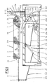
- -fig 1 is a general view of automatic net-packing equipment incorporating an all-mechanical linkage embodiment according to the invention, which is illustrated in a typical operation configuration;
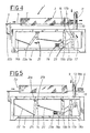
- -figs 2...5 are general views of the automatic equipment as in fig 1, showing certain of the more salient configurations assumed by the mechanical linkage according to the invention in the course of the operating cycle executed by the equipment.
- In fig. 1 of the drawings, 1 denotes automatic equipment for
packing containers 4 of fruit and vegetable produce in a net covering, comprising:
-atube 2, enveloped externally by a long and tightly bunchedtubular net 3 of which theforward end 3a is sealed in readiness to ensheath and wrapsingle containers 4 filled previously with fruit or vegetable produce and fed along the inside of thetube 2 toward theforward end 3a of thenet 3;
-afeed device 5 consisting substantially in alongitudinal element 6 designed to interact with anetting station 8 situated beyond theforwardmost end 2a of thetube 2, which is furnished at itsforward end 6a with at least one spring-loadedprojection 7 directed upwards and designed to register with the rear of thesingle containers 4, inserted into thetube 2 from therear end 2p, and propel them forward together with the ensheathing stretch ofnet 3 toward thenetting station 8. Thissame feed device 5 is also capable of guided reciprocating movement internally of thenet feed tube 2 between a retracted limit position, in which theforward end 6a of thelongitudinal element 6 is encompassed by thefeed tube 2 and completely clear of thenetting station 8, and an extended limit position in which theprojection 7 carried by theforward end 6a of thelongitudinal element 6 lies beyond thenetting station 8. - The
netting station 8 incorporates aguillotine device 9 comprising a pair offixed elements 10 disposed transversely to the feed direction followed by thecontainers 4, parallel one with another and set apart at a distance such as will permit of interacting with a second, moving pair ofelements 11; more exactly, theseelements 11 are positioned above and operated in conjunction with thefixed elements 10, moving in parallel planes marginally offset from those of the latter. - The moving
elements 11 are slidably supported byupright columns 13 and capable thus of traversing vertically between a raised portion (see fig 1), in which the pairs of fixed and movingelements forward end 6a of thelongitudinal element 6 of the feed device carrying acontainer 4 ensheathed by itsnet 3, and a lowered position (see fig 3) in which the opening 12b between the movingelements 11 and thefixed elements 10 is reduced in size, and just sufficient to ensure that thestretch 3a ofnet 3 immediately following thecontainer 4 is retained, correctly positioned, once theforward end 6a of thelongitudinal element 6 has been retracted from thenetting station 8. Automatic net-packing equipment 1 according to the invention further comprises an entirelymechanical linkage 14, which in turn comprises a rod-and-crank mechanism 14a serving to bring about operation of theguillotine device 9, and means 14b by which the operation of the rod-and-crank mechanism 14a itself is synchronized with that of thefeed device 5. - The mechanism denoted 14a comprises:
-arod 18, connected pivotably at oneend 18b with the movingelements 11 of thenetting station 8; -a power driven rotatingcrank element 175 to which therod 18 is rotatably coupled by itsremaining end 18a in such a way that thissame end 18a can be made to describe a controlled trajectory deriving from the rotation of the crank element. - In a preferred embodiment of the invention, the
crank element 175 comprises:
-a fixeddisk 15, rigidly associated with themain frame 1a of the automatic net-packing equipment 1;
-a movingdisk 16, in peripheral contact with and exhibiting the same diameter as the fixeddisk 15;
-a power drivenrevolving crank 17, of which oneend 17a is coupled rotatably to the fixeddisk 15 at its axis of symmetry, and theremaining end 17b to the axis of rotation of the movingdisk 16, in such a way that the movingdisk 16 can be made to roll around thefixed disk 15 and rotate about its own axis at one and the same time. - With the
relative end 18a of therod 18 connected rotatably to the movingdisk 16 at a point near to its periphery, theend 18a in question is obliged to follow an epicyclic trajectory (or epitrochoid, in the particular instance illustrated) occurring simultaneously with and dictated by the orbit of the movingdisk 16 around the fixeddisk 15. - With opportunely selected construction parameters, the rod-and-crank mechanism 14a thus described permits of reciprocating the moving
elements 11 of thenetting station 8 along theircolumns 13 at a variable velocity, which, departing from the fully raised position of theelements 11 and approaching thefixed elements 10, decreases gradually from a maximum initial value to a minimum, reached around the middle of the relative approach trajectory, while at the same moment thelongitudinal element 6 of the feed device retracts at maximum velocity through thenetting station 8 and into thetube 2. In the successive final stage of the trajectory that brings themoving elements 11 toward thefixed elements 10, the velocity picks up and increases progressively. Theelements 11 having duly reversed their direction of movement and begun the reascent to the initial raised position, theforward end 6a of thelongitudinal element 6 will pass through the netting station B at maximum feed velocity carrying a further container for netting. - Means 14b by which the rod-and-crank mechanism 14a is synchronized with the
feed device 5 comprise:
-a power driven revolvingcrank 19, of which oneend 19a is anchored pivotably to theframe 1a of the automatic net-packing equipment 1;
-afirst rod 20 coupled rotatably to the remainingend 19b of the revolvingcrank 19;
-an oscillatingelement 21 affording three ends denoted 21a, 21b and 21c, of which afirst end 21a is pivotably anchored to themain frame 1a of theequipment 1 and asecond end 21b pivotably coupled to thefirst rod 20, thereby enabling receipt of the motion required to produce oscillation about the pivot of thefirst end 21a;
-asecond rod 22, of which oneend 22a is coupled pivotably to thethird end 21c of the oscillatingelement 21 and theremaining end 22b connected to thelongitudinal element 6 of thefeed device 5. - In operation, the movement of the
means 14b thus embodies is synchronized with that of thefeed device 5 in such a way that maximum velocity of thelongitudinal element 6 is generated during passage of itsforward end 6a through thenetting station 8 in each direction. The passages in question are, respectively, that in which thesingle container 4 is carried forward by thelongitudinal element 6 to be netted, and that in which theelement 6 retracts into thefeed tube 2 following separation from thecontainer 4 beyond thenetting station 8. - Both the rod-and-crank mechanism 14a and the feed synchronizing means 14b are set in motion by a
single drive 23, which in the preferred embodiment illustrated in the drawings consists substantially in a gearedmotor 23a to which both thecrank 19 of the synchronizing means 14b and thecrank 17 of the guillotine mechanism 14a are coupled mechanically, in the latter instance by way of aconventional belt transmission 23b. - Accordingly, in the
mechanical linkage 14 proposed, the rod-and-crank mechanism 14a and themeans 14b by which synchronization with thefeed device 5 is achieved are mutually and mechanically interlocked and interdependent, the movement of the one being dictated by that of the other. - The operation of the
mechanical linkage 14 will be more fully appreciated by referring to the sequence of steps illustrated in figs 2, 3, 4 and 5. - Fig 2 illustrates a configuration of the
linkage 14 in which thelongitudinal element 6 of thefeed device 5 is fully retracted in relation to thenet feed tube 2. - In this position, the
forward end 6a of the element is entirely encompassed by theforwardmost end 2a of thetube 2, carrying acontainer 4 engaged from the rear by theprojection 7 and ready for transfer to thenetting station 8. Theguillotine device 9 is positioned with its movingelements 11 lowered against thefixed elements 10 and engaged currently in securing a stretch of net immediately to the rear of acontainer 4 already wrapped and moving away beyond thestation 8. - In the successive step shown in fig 3, the moving
elements 11 reascend to their raised position at progressively increasing velocity, and at the same time, thelongitudinal element 6 advances toward the netting station, likewise at a progressively increasing velocity. - In fig 4, with the moving
elements 11 completing their ascent to the raised position, an opening 12a is created of height sufficient to allow passage of acontainer 4 to thenetting station 8, ensheathed in itsnet 3 and carried by theforward end 6a of thelongitudinal element 6, which at this stage will be moving at maximum feed velocity. - In the following step of fig 5, the raised position has been reached and the moving
elements 11 are seen descending toward thefixed elements 10 in the reverse direction, decelerating gradually from the velocity registering at the initial stage of the descent trajectory; in the particular instance of fig 5, the movingelements 11 are shown completing near to half the descent trajectory and approaching their minimum velocity. At this same juncture, theforward end 6a of thelongitudinal element 6 will have reached its travel limit beyond thenetting station 8 and now, moving in the reverse direction, retracts at increasing velocity toward thenet feed tube 2 leaving thecontainer 4 on the far side; maximum retraction velocity of thelongitudinal element 6 is gained on passing through thenetting station 8 at the moment in which the velocity of themoving elements 11 of theguillotine device 9 is at minimum. - Once the
end 6a of thelongitudinal element 6 has returned through and fully cleared thenetting station 8 on the feed side, the movingelements 11 accelerate again toward the lowered position, fully down against thefixed elements 10. At this point, thelongitudinal element 6 will be fully retracted into thenet feed tube 2 and the configuration of themechanical linkage 14 once again as illustrated in fig 2, whereupon the cycle repeats in the manner described above.
Claims (7)
-a feed device (5) consisting substantially in a longitudinal element (6) designed to interact with the successive netting station (8), which affords a projection (7) at its forward end (6a) positioned in such a way as to register with one side of the single containers (4) and is guidedly reciprocated internally of a net feed tube (2) between a first limit position in which the forward end (6a) is retracted and completely encompassed by the tube, clear of the netting station (8), and a second limit position in which the projection (7) afforded by its forward end (6a) is extended beyond the netting station (8);
-a guillotine device (9), constituting a part of the netting station (8) and consisting in a fixed first pair of elements (10) disposed transversely to the feed direction of the containers (4) and designed to operate in conjuction with a moving second pair of elements (11) located above the first and capable of vertical movement in either direction between a raised position, in which the pairs of fixed and moving elements (10, 11) afford an opening (12a) freely allowing passage of the longitudinal element (6) together with a single container (4) ensheathed by its net (3), and a lowered position in which the moving elements (11) combine with the fixed elements (10) to create a smaller opening (12b) just sufficient to secure and position the stretch of net (3) immediately to the rear of each container (4),
characterized
in that it comprises:
-a rod-and-crank mechanism (14a) serving to operate the guillotine device (9), consisting in a rod (18) of which one end (18b) is connected pivotably with the moving elements (11) of the netting station (8) and the remaining end (18a) connected pivotably and eccentrically to a moving disk (16), and a power driven revolving crank element (175), by which the moving disk (16) is carried rotatably and invested at each revolution with a controlled rotating and rolling motion in such a way as to reciprocate the moving elements (11) of the guillotine device (9) at variable velocity through a trajectory that comprises departure from the raised position toward the fixed elements (10), with the velocity of the moving elements (11) decreasing progressively from a maximum initial value to a minimum value reached substantially in mid-descent, at which juncture the forward end (6a) of the longitudinal element (6) passes through the netting station (8) retracting at maximum velocity toward the net feed tube (2), followed by continuation through the final stage of the approach toward the fixed elements (10) at increasing velocity, whereupon the direction of movement is reversed and the moving elements (11) reascend at progressively increasing velocity toward the raised position, at which juncture the forward end (6a) of the longitudinal element (6) passes through the netting station (8) at maximum feed velocity carrying a further container (4) for netting: and
-means (14b) by which the operation of the rod-and-crank mechanism (14a) is synchronized with that of the feed device (5).
-a power driven revolving crank (19), of which one end (19a) is anchored pivotably to the frame (1a) of the automatic equipment (1);
-a first rod (20) coupled rotatably to the opposite end (19b) of the revolving crank (19);
-an oscillating element (21) affording three ends (21a, 21b, 21c) of which a first end (21a) is pivotably anchored to the main frame (1a) of the automatic equipment (1) and a second end (21b) pivotably coupled to the first rod (20) in such a way as to receive the motion required to produce oscillation about the pivot of the first end (21a);
-a second rod (22), of which one end (22a) is coupled pivotably to the third end (21c) of the oscillating element (21) and the remaining end (22b) hinged to the longitudinal element (6) of the feed device, in such a way that the longitudinal element (6) is invested with maximum velocity during the states in which its forward end (6a) passes through the netting station (8).
-a fixed disk (15), rigidly associated with the frame (1a) of the automatic equipment (1);
-a power driven revolving crank arm (17), of which one end (17a) is coupled rotatably to the fixed disk (15) at its axis of symmetry and the remaining end (17b) to the axis of rotation of the moving disk (16), in such a way that the moving disk (16) is made by the crank (17) to roll around the fixed disk (15) and rotate about its own axis at one and the same time.
Applications Claiming Priority (2)
| Application Number | Priority Date | Filing Date | Title |
|---|---|---|---|
| IT00367789A IT1236145B (en) | 1989-10-27 | 1989-10-27 | MECHANICAL KINEMATISM FOR CONTEMPORARY AND SYNCHRONOUS HANDLING OF THE FORWARD DEVICE AND THE STACKING SCREENING STATION OF CONTAINERS OF FRUIT AND VEGETABLE PRODUCTS FOR AUTOMATIC EQUIPMENT FOR THE PACKAGING OF BATCHED SCREENINGS. |
| IT367789 | 1989-10-27 |
Publications (2)
| Publication Number | Publication Date |
|---|---|
| EP0425445A1 true EP0425445A1 (en) | 1991-05-02 |
| EP0425445B1 EP0425445B1 (en) | 1994-03-30 |
Family
ID=11111338
Family Applications (1)
| Application Number | Title | Priority Date | Filing Date |
|---|---|---|---|
| EP90830388A Expired - Lifetime EP0425445B1 (en) | 1989-10-27 | 1990-08-31 | A mechanical linkage providing simultaneous and synchronized operation of the feed device and netting station by which containers of fruit and vegetable produce are wrapped in automatic netpacking equipment |
Country Status (4)
| Country | Link |
|---|---|
| EP (1) | EP0425445B1 (en) |
| DE (1) | DE69007742T2 (en) |
| ES (1) | ES2050999T3 (en) |
| IT (1) | IT1236145B (en) |
Cited By (3)
| Publication number | Priority date | Publication date | Assignee | Title |
|---|---|---|---|---|
| WO2006135566A1 (en) * | 2005-06-09 | 2006-12-21 | Tipper Tie, Inc. | Breech loader packaging apparatus and associated devices, methods, systems and computer program products |
| US7587880B2 (en) | 2007-12-05 | 2009-09-15 | Tipper Tie, Inc. | System for enclosing a product in a covering material |
| EP3738719A1 (en) | 2019-05-13 | 2020-11-18 | IGZ Ingenieurgesellschaft für logistische Informationssysteme mbH | Mobile picking robot, goods-to-person picking workstation and picking system |
Citations (1)
| Publication number | Priority date | Publication date | Assignee | Title |
|---|---|---|---|---|
| EP0123655A2 (en) * | 1983-03-25 | 1984-10-31 | SORMA S.r.l. | Automatic apparatus for packaging fruit and vegetables containers by means of a net like wrapping presenting supporting tapes and labels |
-
1989
- 1989-10-27 IT IT00367789A patent/IT1236145B/en active IP Right Grant
-
1990
- 1990-08-31 DE DE69007742T patent/DE69007742T2/en not_active Expired - Fee Related
- 1990-08-31 EP EP90830388A patent/EP0425445B1/en not_active Expired - Lifetime
- 1990-08-31 ES ES90830388T patent/ES2050999T3/en not_active Expired - Lifetime
Patent Citations (1)
| Publication number | Priority date | Publication date | Assignee | Title |
|---|---|---|---|---|
| EP0123655A2 (en) * | 1983-03-25 | 1984-10-31 | SORMA S.r.l. | Automatic apparatus for packaging fruit and vegetables containers by means of a net like wrapping presenting supporting tapes and labels |
Cited By (8)
| Publication number | Priority date | Publication date | Assignee | Title |
|---|---|---|---|---|
| WO2006135566A1 (en) * | 2005-06-09 | 2006-12-21 | Tipper Tie, Inc. | Breech loader packaging apparatus and associated devices, methods, systems and computer program products |
| US7392635B2 (en) | 2005-06-09 | 2008-07-01 | Tipper Tie, Inc. | Breech loader packaging systems and associated breech loading chutes and methods |
| US7793486B2 (en) | 2005-06-09 | 2010-09-14 | Tipper Tie, Inc. | Breech loader packaging apparatus and methods |
| US7925379B2 (en) | 2005-06-09 | 2011-04-12 | Tipper Tie, Inc. | Computer program products for packaging systems with breech loading chutes |
| US7975454B2 (en) | 2005-06-09 | 2011-07-12 | Tipper Tie, Inc. | Breech loader packaging systems and associated methods |
| US8209945B2 (en) | 2005-06-09 | 2012-07-03 | Tipper Tie, Inc. | Breech loader chutes for packaging systems |
| US7587880B2 (en) | 2007-12-05 | 2009-09-15 | Tipper Tie, Inc. | System for enclosing a product in a covering material |
| EP3738719A1 (en) | 2019-05-13 | 2020-11-18 | IGZ Ingenieurgesellschaft für logistische Informationssysteme mbH | Mobile picking robot, goods-to-person picking workstation and picking system |
Also Published As
| Publication number | Publication date |
|---|---|
| DE69007742T2 (en) | 1994-07-14 |
| IT8903677A0 (en) | 1989-10-27 |
| DE69007742D1 (en) | 1994-05-05 |
| ES2050999T3 (en) | 1994-06-01 |
| EP0425445B1 (en) | 1994-03-30 |
| IT1236145B (en) | 1993-01-11 |
Similar Documents
| Publication | Publication Date | Title |
|---|---|---|
| CN100435704C (en) | Device for production of a drink by infusion | |
| US6138442A (en) | Packaging machine with continuous sealing jaw movement | |
| CA1323830C (en) | Combined blousing, stripping and sealing for bag forming and method | |
| US5425215A (en) | Apparatus for packaging loose leaf material | |
| DE3141431C2 (en) | Device for manufacturing, filling and closing bags | |
| US5203145A (en) | Stripper mechanism for a tubular bag packaging machine | |
| US4870802A (en) | Machines and methods for doubling the capacity of packaging machines | |
| DE3800943C2 (en) | ||
| US4063400A (en) | Continuous film sealing machine | |
| JPH06122417A (en) | Putting and sealing device | |
| EP0469288B1 (en) | Method and apparatus for packaging bulk materials | |
| US5062253A (en) | Combined film feeding stripping and sealing for bag forming and method | |
| JP2007112512A (en) | Portioning and packaging apparatus and method | |
| EP0425445A1 (en) | A mechanical linkage providing simultaneous and synchronized operation of the feed device and netting station by which containers of fruit and vegetable produce are wrapped in automatic netpacking equipment | |
| US4265074A (en) | Web processing mechanism for forming packages | |
| US2877609A (en) | Machine for making bags from a continuous web | |
| US7383672B2 (en) | Package assembly and machine and method for manufacture thereof | |
| JP2000508277A (en) | Packaging machine | |
| CN102673817B (en) | Closing and sealing device of plastic object bags | |
| US4518378A (en) | Apparatus for the manufacture of plastic bags | |
| JPS5820606A (en) | Device for packing powdered, granular, lumpy, pasty and liquefied package by tubular foil | |
| CN209719969U (en) | The packing machine that food product processing is just cleared up with antiseize | |
| US4331436A (en) | Machine for erecting and counterfolding collapsed boxes | |
| DE1902379A1 (en) | Packing machine | |
| EP0861785B1 (en) | Poker for unblocking the filling nozzle of a packaging machine |
Legal Events
| Date | Code | Title | Description |
|---|---|---|---|
| PUAI | Public reference made under article 153(3) epc to a published international application that has entered the european phase |
Free format text: ORIGINAL CODE: 0009012 |
|
| AK | Designated contracting states |
Kind code of ref document: A1 Designated state(s): DE ES FR GB |
|
| 17P | Request for examination filed |
Effective date: 19910617 |
|
| 17Q | First examination report despatched |
Effective date: 19920903 |
|
| RAP1 | Party data changed (applicant data changed or rights of an application transferred) |
Owner name: SORMA S.R.L. |
|
| GRAA | (expected) grant |
Free format text: ORIGINAL CODE: 0009210 |
|
| AK | Designated contracting states |
Kind code of ref document: B1 Designated state(s): DE ES FR GB |
|
| REF | Corresponds to: |
Ref document number: 69007742 Country of ref document: DE Date of ref document: 19940505 |
|
| ET | Fr: translation filed | ||
| REG | Reference to a national code |
Ref country code: ES Ref legal event code: FG2A Ref document number: 2050999 Country of ref document: ES Kind code of ref document: T3 |
|
| PLBE | No opposition filed within time limit |
Free format text: ORIGINAL CODE: 0009261 |
|
| STAA | Information on the status of an ep patent application or granted ep patent |
Free format text: STATUS: NO OPPOSITION FILED WITHIN TIME LIMIT |
|
| 26N | No opposition filed | ||
| PGFP | Annual fee paid to national office [announced via postgrant information from national office to epo] |
Ref country code: GB Payment date: 19980824 Year of fee payment: 9 |
|
| PGFP | Annual fee paid to national office [announced via postgrant information from national office to epo] |
Ref country code: DE Payment date: 19980907 Year of fee payment: 9 |
|
| PG25 | Lapsed in a contracting state [announced via postgrant information from national office to epo] |
Ref country code: GB Free format text: LAPSE BECAUSE OF NON-PAYMENT OF DUE FEES Effective date: 19990831 |
|
| GBPC | Gb: european patent ceased through non-payment of renewal fee |
Effective date: 19990831 |
|
| PG25 | Lapsed in a contracting state [announced via postgrant information from national office to epo] |
Ref country code: DE Free format text: LAPSE BECAUSE OF NON-PAYMENT OF DUE FEES Effective date: 20000601 |
|
| PGFP | Annual fee paid to national office [announced via postgrant information from national office to epo] |
Ref country code: FR Payment date: 20090814 Year of fee payment: 20 Ref country code: ES Payment date: 20090902 Year of fee payment: 20 |
|
| REG | Reference to a national code |
Ref country code: ES Ref legal event code: FD2A Effective date: 20100901 |