EP0426099B1 - Ultrasonic transducer - Google Patents
Ultrasonic transducer Download PDFInfo
- Publication number
- EP0426099B1 EP0426099B1 EP90120780A EP90120780A EP0426099B1 EP 0426099 B1 EP0426099 B1 EP 0426099B1 EP 90120780 A EP90120780 A EP 90120780A EP 90120780 A EP90120780 A EP 90120780A EP 0426099 B1 EP0426099 B1 EP 0426099B1
- Authority
- EP
- European Patent Office
- Prior art keywords
- transducer
- electrodes
- electrode
- width
- ultrasonic
- Prior art date
- Legal status (The legal status is an assumption and is not a legal conclusion. Google has not performed a legal analysis and makes no representation as to the accuracy of the status listed.)
- Expired - Lifetime
Links
- 229910052799 carbon Inorganic materials 0.000 claims description 20
- 238000001514 detection method Methods 0.000 claims description 13
- 230000007423 decrease Effects 0.000 claims description 6
- 239000000523 sample Substances 0.000 description 30
- 230000005855 radiation Effects 0.000 description 9
- 229910003460 diamond Inorganic materials 0.000 description 8
- 239000010432 diamond Substances 0.000 description 8
- 238000000034 method Methods 0.000 description 8
- 238000003745 diagnosis Methods 0.000 description 5
- 241001465754 Metazoa Species 0.000 description 4
- 238000003491 array Methods 0.000 description 3
- 239000002305 electric material Substances 0.000 description 3
- 238000010420 art technique Methods 0.000 description 2
- 239000000919 ceramic Substances 0.000 description 2
- 230000000694 effects Effects 0.000 description 2
- 238000005530 etching Methods 0.000 description 2
- 229910052451 lead zirconate titanate Inorganic materials 0.000 description 2
- WABPQHHGFIMREM-UHFFFAOYSA-N lead(0) Chemical compound [Pb] WABPQHHGFIMREM-UHFFFAOYSA-N 0.000 description 2
- 238000004519 manufacturing process Methods 0.000 description 2
- 230000008878 coupling Effects 0.000 description 1
- 238000010168 coupling process Methods 0.000 description 1
- 238000005859 coupling reaction Methods 0.000 description 1
- 239000013078 crystal Substances 0.000 description 1
- 238000010586 diagram Methods 0.000 description 1
- 230000008020 evaporation Effects 0.000 description 1
- 238000001704 evaporation Methods 0.000 description 1
- HFGPZNIAWCZYJU-UHFFFAOYSA-N lead zirconate titanate Chemical compound [O-2].[O-2].[O-2].[O-2].[O-2].[Ti+4].[Zr+4].[Pb+2] HFGPZNIAWCZYJU-UHFFFAOYSA-N 0.000 description 1
- 239000000463 material Substances 0.000 description 1
- 239000002184 metal Substances 0.000 description 1
- 238000012986 modification Methods 0.000 description 1
- 230000004048 modification Effects 0.000 description 1
- 229920002050 silicone resin Polymers 0.000 description 1
Images


Classifications
-
- B—PERFORMING OPERATIONS; TRANSPORTING
- B06—GENERATING OR TRANSMITTING MECHANICAL VIBRATIONS IN GENERAL
- B06B—METHODS OR APPARATUS FOR GENERATING OR TRANSMITTING MECHANICAL VIBRATIONS OF INFRASONIC, SONIC, OR ULTRASONIC FREQUENCY, e.g. FOR PERFORMING MECHANICAL WORK IN GENERAL
- B06B1/00—Methods or apparatus for generating mechanical vibrations of infrasonic, sonic, or ultrasonic frequency
- B06B1/02—Methods or apparatus for generating mechanical vibrations of infrasonic, sonic, or ultrasonic frequency making use of electrical energy
- B06B1/06—Methods or apparatus for generating mechanical vibrations of infrasonic, sonic, or ultrasonic frequency making use of electrical energy operating with piezoelectric effect or with electrostriction
- B06B1/0607—Methods or apparatus for generating mechanical vibrations of infrasonic, sonic, or ultrasonic frequency making use of electrical energy operating with piezoelectric effect or with electrostriction using multiple elements
- B06B1/0622—Methods or apparatus for generating mechanical vibrations of infrasonic, sonic, or ultrasonic frequency making use of electrical energy operating with piezoelectric effect or with electrostriction using multiple elements on one surface
Definitions
- the present invention relates to ultrasonic transducers.
- Ultrasonic transducer arrays i.e. ultrasonic probes comprising arranged pluralities of rectangular transducer elements, are widely used as probes for electronically scanning ultrasonic beams.
- Such an ultrasonic probe should, desirably, provide a narrow beam over a range from near field to far field, if high resolution ultrasonic detection or examination equipment is to be realised.
- Improvements in resolution characteristics in the array direction have been sought by utilising electronic control of phase or amplitude of the transmitting or receiving wave of each transducer element, whilst in relation to the Y axis direction (perpendicular to the azimuth plane) the utilisation of acoustic lenses has been proposed.
- the following technique has been employed with a view to improving beam characteristics in the Y axis direction, from near field to far field.
- Fig. 1(a) is a perspective view of an ordinary ultrasonic transducer array, i.e. an ultrasonic probe comprising an arranged plurality of rectangular transducer elements 1. These rectangular elements are formed by dicing a piezo-electric ceramic plate, having electrodes on its two main surfaces, in the Y direction. Electrodes on one of the main surfaces are led out to the apparatus body by a flexible print card FPC 4 as ground electrodes, whilst electrodes on the other surface are led out as signal electrodes.
- FPC 4 flexible print card
- the main surface radiating the ultrasonic power (uppermost in Fig. 1(a)) generally carries ground electrodes; however, signal electrodes, which would not actually be seen in Fig. 1(a), are drawn on the radiation surface (uppermost in Fig. 1(a)) in Fig. 1(a) and other Figures, for convenience of explanation.
- Fig. 1(b) illustrates signal electrode pattern, namely shape of aperture, of each transducer element 1 and its shading function, which indicates weighting of radiation power provided from the element.
- the weighting is substantially proportional to electrode width in the X axis direction (perpendicular to Y and Z axes). Therefore, in the case of rectangular electrodes as shown in Fig. 1(b), where the shading function is flat or uniform, no weighting is effected.
- the azimuth plane is a plane in which an ultrasonic beam is scanned in the axial direction (Z axis direction) perpendicular to the surface of transducer array, as shown in Fig. 1(a).
- An acoustic lens 3 is provided to narrow down the ultrasonic beam width in the Y axis direction.
- Fig. 2 illustrates ultrasonic beam widths when a lens with focal distance of 140 mm is employed, for beams radiated from a probe which is 20 mm wide in the axis Y direction.
- the curves (A) and (B) in Fig. 2 shown beam widths corresponding to values which are -10 dB and -20 dB lower than the centre value, respectively.
- a narrow beam can be obtained in the vicinity of the focal distance 140 mm of the lens, but the beam width becomes greater in fields both nearer to and farther from the probe than the focal distance of the lens.
- a probe which is structured so that the Y direction width of a transducer element, namely the aperture, is selected in dependence upon the desired diagnosis distance, is illustrated in Fig. 3 (see also EP-A 0 212 737).
- the signal electrode of a transducer element is divided into three parts, A, B and A', to provide three signal electrodes.
- Central signal electrode B is selected for diagnosis in a near field, i.e. at a distance less than the focal distance
- signal electrodes A, B and A' are used for diagnosis in a far field, i.e. at a distance longer than the focal distance.
- the -10 dB beam width (A) is improved around the focal distance, but the -20 dB beam width (B) is not improved.
- Fig. 5 illustrates a third prior art technique, such as is disclosed in U.S. Patent No. 4,425,525 (see also GB-A-2 114 856), in which beam width is further narrowed by weighting radiation power in the Y direction.
- radiation power is weighted by providing different signal electrode widths in the X axis direction for different positions along each transducer in the longitudinal direction (Y direction), as shown in the shading function of Fig. 5.
- the signal electrodes have a diamond shape in Fig. 5.
- the -20 dB beam width (B) before and beyond the focal point of the lens is improved.
- improvement in the -10 dB beam width (A) in the near field, before the focal point is still insufficient.
- Fig. 7 indicates a fourth prior art technique, combining the techniques of Figs. 3 and 5.
- a piezo-electric ultrasonic transducer comprising a transducer element the length of which in a Y direction is greater than its width in an X direction, perpendicular to the Y direction, having major surfaces in Y-X planes, and operable to radiate ultrasonic power in a Z direction, perpendicular to those planes, the transducer element having a plurality of electrodes on one of its major surfaces, the plurality of electrodes comprising:- at least one first electrode located generally longitudinally centrally of the main surface, having a first length, in the Y direction, and being less wide, in the X direction, at its opposite longitudinal ends than at an X-directed centre line thereof, at least two second electrodes located to respective longitudinally opposite sides of said centre line, each of said two second electrodes being less wide, in the X direction, at its end longitudinally remote from the centre line than at a maximum-width portion thereof which is closer to or at said centre line, characterised in that the two second electrode
- An embodiment of the present invention can provide for the realisation of a high-resolution ultrasonic detection or examination apparatus, for example for use in providing information which may be employed for diagnosis in relation to the human or animal body, and/or for the realisation of an ultrasonic probe which affords a narrow ultrasonic beam particularly in a direction orthogonal to its scan plane, for both near and far fields.
- An embodiment of the present invention can provide an ultrasonic transducer or ultrasonic probe for realising high resolution ultrasonic examination equipment by sharpening the ultrasonic beam width in a direction of elevation orthogonally crossing azimuth plane (in the Y axis direction).
- a plurality of rectangular piezo-electric ultrasonic transducer elements are laterally aligned to form an array, each transducer element having first and second signal electrodes on one of its surfaces.
- the first signal electrode is located towards the centre of the transducer element, so as to have a first length in the longitudinal direction of the transducer element and a first width, along a lateral centre line transverse to the longitudinal direction of the transducer element.
- Two second signal electrodes are arranged outside the first electrode, symmetrically with respect to the lateral centre line.
- the two second signal electrodes have a second length in the longitudinal direction of the transducer element longer than the first length, and have a second width almost the same as the first width, along the lateral centre line.
- diamond-shaped electrode forms for instance, excellent for providing an ultrasonic beam narrow in the electrode's longitudinal direction, can be effectively realised both by the first signal electrode and by the combination of the first and second signal electrodes connected all together.
- Diamond-shaped signal electrodes radiate ultrasonic power weighted more towards their central portions than their longitudinal end portions.
- the first signal electrode is used to transmit an ultrasonic beam which is narrow at a distance shorter than the focal length of an acoustic lens provided on the transducer's surface, and the combination of the first and second signal electrodes is used to transmit an ultrasonic beam which is narrow at another distance longer than the focal length, so that a sharp or narrow beam can be provided for both short and long distances for ultrasonic examination, for example of the human or animal body.
- a transducer array namely a probe, in accordance with an embodiment of the present invention will be described with reference to Figs. 9 to 11.
- Each transducer element 1 of the array is formed with lead zirconate titanate crystal Pb(Ti,Zr)O3 (generally referred to as PZT) ceramic and is, for example, 0.6 mm in width (in the X direction), 20 mm in length (in the Y direction) and about 0.45 mm in thickness (in the Z direction).
- PZT lead zirconate titanate crystal
- 100 to 200 transducer elements 1 are arranged one after another to form the array.
- Metal films are provided on two surfaces of each transducer element 1, usually deposited by evaporation, so as to form electrodes.
- the film electrode on one of the surfaces of the transducer element 1 is divided to form diamond shapes, for example by an etching method, as illustrated, so that signal electrodes A, B and A' are formed.
- first signal electrode B The longitudinal length of a first signal electrode B is, for example, 10 to 20 mm. Longitudinal (Y direction) ends of second signal electrodes A and A' extend to reach the longitudinal length "a" (see Fig. 11(a)) of the transducer element.
- These signal electrodes e.g. A, B. A'
- the first signal electrode B is diamond-shaped and generally longitudinally centrally located of the transducer element.
- the second signal electrodes A, A' are V-shaped, with the open end of the V directed towards the longitudinal centre of the transducer element. Together, however, the electrodes A and A' (and B) have a diamond-shaped outline.
- Second signal electrodes A and A' are led out by lead wires 5a provided on a flexible print card 4 (hereinafter referred to as an FPC) and are connected with each other on the FPC 4.
- First signal electrodes B are led out by lead wires 5b on FPC 4.
- a lead wire 5a is connected or disconnected, in accordance with a predetermined sequence, to or from a lead wire 5b, by a driving circuit which will be explained below.
- first and second signal electrodes A, B and A' are driven simultaneously so as to have a sufficiently weighted aperture of width "a" having a triangle shading function B + A + A' as shown in Fig. 11(b).
- first signal electrode B is driven and ultrasonic power is radiated from an aperture of width "b" sufficiently weighted by a triangle shading function B shown in Fig. 11(a).
- the film electrode formed on the other surface of a transducer element 1, normally on the front surface, is grounded as a common electrode.
- a backing 2 made of a material which absorbs ultrasonic beam well may be provided to attenuate ultrasonic radiation towards the rear.
- the maximum examination distance is about 160 mm when the array is applied to examination of the human or animal body. Therefore, there is provided on the radiation surface of transducer array an acoustic lens 3, which functions as a convex lens for ultrasonic waves of 3.5 MHz, which is the resonance frequency of the 0.45 mm thick transducer elements.
- the lens is, for example, formed using silicone resin having a cylindrical surface such as to provide a focal distance of approximately 140 mm.
- the first signal electrode B having the shorter aperture width "b" in the Y direction is effective for reducing the beam width in the range from the focal distance of the acoustic lens 3 down to about the 90 mm distant field, nearer than the focal distance of the lens.
- the parallel connection of all the signal electrodes A, A' and B having the wider aperture "a" in the Y direction is effective for reducing the beam width at the approximately 150 mm distant field, and accordingly contributes to improvement of characteristic in the far field, beyond the focal distance of acoustic lens 3.
- the transducer has been indicated to be used for transmitting ultrasonic waves.
- the same ultrasonic transducer may be used for receiving ultrasonic waves.
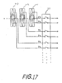
- FIG. 17 A circuit configuration which may be employed in ultrasonic detection equipment employing the above-described transducer array is illustrated in Fig. 17.
- Lead wires 5a and 5b from second signal electrodes A and A' and first signal electrodes B of transducer elements 1-1, 1-2, ... are connected directly or via amplifier transistors to terminals of switches 21.
- Opposite terminals of switches 21 are selectively connected to a transducer driving circuit (a pulser), or to a receiving circuit to receive ultrasonic signals after reflection from an object in the human body for instance (hereinafter referred to as echo) according to a predetermined sequence.
- An output of a receiving circuit is input to a display unit so as to be displayed thereon.
- Ultrasonic beam characteristics provided by array of Fig. 9 are illustrated in Fig. 12. As seen in this Figure, the improvement provided in relation to the -20 dB beam width (B) is distinctive in comparison with the prior art, providing for a narrow ultrasonic beam over all examination fields (distances).
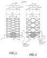
- Fig. 13 illustrates configuration and shading function of transducer array of a second embodiment of the present invention.
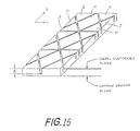
- Fig. 15 is a perspective view for assistance in explanation of a method which may be employed in relation to the second embodiment, and the third embodiment explained below, for dividing or dicing a piezo-electric material plate for providing transducer elements.
- a piezo-electric material plate having electrodes on its two surfaces is divided by dicing in two directions P and Q, each obliquely crossing the X axis and mutually-crossing symmetrically with respect to the X axis.
- dicing lines or grooves are formed in parallel with a selected pitch, for example a pitch such that two lines in the direction concerned are provided per single transducer element. Dicing may also be effected in the Y direction.
- a plurality of divided elements are formed.
- the width of a groove formed by the dicing is about 0.05 mm, and its depth d is about 0.4 mm.
- FIG. 13 four divided elements or regions A, A', B and B' constitute a single transducer element which corresponds to single transducer element 1 of Fig. 10.
- Divided elements or regions B and B', providing a short aperture l2 are selected for near field detection, and all the divided elements or regions, A, A', B and B', providing a wider aperture l1, are selected for far field detection.
- the respective aperture sizes l1 and l2 can provide the weighting in Y axis direction similar to that in the first embodiment, as indicated by the shading functions in Fig. 13.
- Individual electrodes B and B' are diamond-shaped, and individual electrodes A and A' are substantially diamond-shaped. Considered together, A and A' (and B, B') fall within a diamond-shaped outline.
- Fig. 14 illustrates configuration and shading functions of a transducer array of a third embodiment of the present invention.
- grooves in the Y direction are additionally provided so as to separate the transducer elements.
- Electrode D is diamond-shaped. Individual electrodes C and C' are substantially triangular. Considered together, C and C' (and D) fall within a diamond-shaped outline.
- the divided elements for example, E to K in Fig. 15, are still physically connected with each other at their bottom side, below the dicing grooves.
- the elements may be separated perfectly.
- the signal electrodes may be patterned by etching electrodes.
- the electrode patterns of Figs. 13, 14 and 15 can be formed by dicing. Dividing elements by the dicing method causes less acoustic coupling between adjacent divided elements, thereby reducing undesirable radiation from adjacent elements.
- Fig. 12 illustrates ultrasonic beam width characteristics of the transducer array described in the first embodiment, having a configuration where the focal distance of acoustic lens 3 is set to 140 mm, which is greater than 3/4, i.e. 120 mm, of the maximum examination depth 160 mm of ultrasonic examination equipment with which the array is to be used.
- Fig. 16 illustrates ultrasonic beam width characteristics for a focal distance set to 100 mm, which is less than 3/4 of the maximum examination depth.
- the ultrasonic beam spreads at the deep examination zone.
- a uniform and narrow ultrasonic beam can be provided over the entire examination zone.
- the maximum examination depth of a probe having the resonance frequency of 3.5 MHz is about 160 mm (for the human or animal body); and the maximum examination depth of a probe about 0.32 mm thick and having the resonance frequency of 5.0 MHz is about 110 mm. Therefore, the focal distance of acoustic lens 3 should be desirably set to 120 mm or longer, and 80 mm or longer, respectively, which are three-quarters of the respective maximum examination depths, so as to obtain high resolution in both near and far fields.
- an embodiment of the present invention provides a probe having a plurality of aperture types such that sufficient weighting is afforded for the respective different aperture types.
- the ultrasonic beam width in a short axis (Y) direction of the probe is reduced for both near and far field detection or examination, which contributes to the provision of high resolution ultrasonic examination equipment.
- an acoustic lens is provided at the radiation surface of a transducer array in the above-described embodiments, it will be apparent that embodiments of the present invention can also be applied where no acoustic lens is used.
- Embodiments of the present invention can be used not only in equipment for use in examination or diagnosis in relation to the human body but also in ultrasonic radar apparatus to detect other objects, for example an ultrasonic flaw detector, etc.
- a plurality of piezo-electric ultrasonic sector transducers are aligned to form an array, with first and second electrodes on the radiating surfaces of each sector transducer.
- the first electrode is located on a centre line of the sector transducer's length, and has a first length in the longitudinal direction and a first width along the centre line.
- Two of the second electrodes are arranged outside the first electrode, symmetrically to the centre line.
- the two second electrodes have a second length in the longitudinal direction longer than the first length, and have a second width almost same to the first width, along or near the centre line.
- effectively diamond-shaped electrodes excellent for providing a beam narrow in the longitudinal direction can be employed in relation to the first electrode and the combination of the first and second electrodes connected with each other.
- the first electrode is selected to provide a ultrasonic beam narrow at a distance shorter than a focal length of an acoustic lens provided on the transducers, and the combination of the first and second electrodes are used to provide a ultrasonic beam narrow in another distance substantially longer than the focal length, so that a sharp beam can be delivered to both the short distance and long distance.
- An embodiment of the present invention provides a piezo-electric ultrasonic transducer long in Y direction and short in X direction, the transducer having major surfaces parallel to X and Y directions, the transducer radiating an ultrasonic power in Z direction orthogonal to X and Y directions, the transducer comprising:- a plurality electrodes on one of the major surfaces, said electrodes comprising:- at least one of first electrodes located on a centre line of Y direction length of the transducer, said first electrode having a first length Y direction, said first electrode having a first width in X direction at a central portion of said first length and having a second width at Y direction ends thereof, said first width being wider than said second width; and at least two of second electrodes arranged respectively on both sides of said centre line, outlines of said two second electrodes having a second length in Y direction substantially longer than said first length, said outlines of said second electrodes having a third width at the central portion of said second length and having a fourth width at Y
- the width of said first electrode may gradually decrease from said first width to said second width.
- the width of said outlines of said second electrodes may gradually decrease from said third width to said fourth width.
- the first electrode and said second electrodes may be symmetric with respect to said centre line or a mid-point of said transducer.
- the first electrode may be substantially of diamond shape.
- the outlines of said second electrodes may be substantially of diamond shape.
- the second width may be less than approximately 0.5 of said first width.
- the second width may be less than approximately 0.3 of said first width.
- the fourth width may be less than approximately 0.5 of said third width.
- the fourth width may be less than approximately 0.3 of said third width.
- the ratio of said decrease from said first width to said second width may be substantially equal to the ratio of said decrease from said third width to said fourth width.
- the transducer may further comprise an acoustic lens thereon for focusing ultrasonic beam radiated therefrom, said acoustic lens having a focal length for said ultrasonic beam.
- the focal length may be chosen longer than approximately three-quarters of a maximum detectable distance of said transducer.
- the focal length may be chosen substantially longer than said first distance and substantially shorter than said second distance.
- a plurality of said transducers may be aligned in X direction so as to form a transducer array.
- a grounding electrode may be provided on another one of the major surfaces of the or each transducer.
- An embodiment of the present invention provides an ultrasonic detection apparatus comprising:- a plurality of piezo-electric ultrasonic transducer elements long in Y direction and short in X direction orthogonal to Y direction, said transducer element having major surfaces parallel to X and Y directions, said transducer element radiating an ultrasonic power in Z direction orthogonal to X and Y directions, each of said transducer elements comprising:- a plurality electrodes on one of the major surfaces, said electrodes comprising:- at least one of first electrodes located on a centre line of Y direction length of the transducer, said first electrode having a first length in the longitudinal Y direction, said first electrode having a first width in X direction at a central portion of said first length and having a second width at longitudinal ends thereof, said first width being wider than said second width; and at least two of second electrodes arranged respectively on both sides of said centre line, outlines of said two second electrodes having a second length in Y direction substantially longer than said first length, said outlines
- the plurality of said transducer elements may be aligned in X direction so as to form a transducer array, and after said electronic circuit completes said sequence for one of said transducers said electronic circuit it may be switched to a transducer adjacent thereto so as to repeat said sequence.
- the array may comprise an acoustic lens thereon for focusing ultrasonic beam radiated therefrom.
Description
- The present invention relates to ultrasonic transducers.
- Ultrasonic transducer arrays, i.e. ultrasonic probes comprising arranged pluralities of rectangular transducer elements, are widely used as probes for electronically scanning ultrasonic beams. Such an ultrasonic probe should, desirably, provide a narrow beam over a range from near field to far field, if high resolution ultrasonic detection or examination equipment is to be realised.
- Improvements in resolution characteristics in the array direction (i.e. in the azimuth or Z axis direction) have been sought by utilising electronic control of phase or amplitude of the transmitting or receiving wave of each transducer element, whilst in relation to the Y axis direction (perpendicular to the azimuth plane) the utilisation of acoustic lenses has been proposed.
- However, there is a problem in relation to beam width in the Y axis direction in that the beam becomes wide in fields other than that in the vicinity of the focal point of the acoustic lens.
- The following technique has been employed with a view to improving beam characteristics in the Y axis direction, from near field to far field.
- Fig. 1(a) is a perspective view of an ordinary ultrasonic transducer array, i.e. an ultrasonic probe comprising an arranged plurality of
rectangular transducer elements 1. These rectangular elements are formed by dicing a piezo-electric ceramic plate, having electrodes on its two main surfaces, in the Y direction. Electrodes on one of the main surfaces are led out to the apparatus body by a flexible print card FPC 4 as ground electrodes, whilst electrodes on the other surface are led out as signal electrodes. - The main surface radiating the ultrasonic power (uppermost in Fig. 1(a)) generally carries ground electrodes; however, signal electrodes, which would not actually be seen in Fig. 1(a), are drawn on the radiation surface (uppermost in Fig. 1(a)) in Fig. 1(a) and other Figures, for convenience of explanation.
- Fig. 1(b) illustrates signal electrode pattern, namely shape of aperture, of each
transducer element 1 and its shading function, which indicates weighting of radiation power provided from the element. The weighting is substantially proportional to electrode width in the X axis direction (perpendicular to Y and Z axes). Therefore, in the case of rectangular electrodes as shown in Fig. 1(b), where the shading function is flat or uniform, no weighting is effected. - The azimuth plane is a plane in which an ultrasonic beam is scanned in the axial direction (Z axis direction) perpendicular to the surface of transducer array, as shown in Fig. 1(a).
- An
acoustic lens 3 is provided to narrow down the ultrasonic beam width in the Y axis direction. - Fig. 2 illustrates ultrasonic beam widths when a lens with focal distance of 140 mm is employed, for beams radiated from a probe which is 20 mm wide in the axis Y direction. The curves (A) and (B) in Fig. 2 shown beam widths corresponding to values which are -10 dB and -20 dB lower than the centre value, respectively. As is apparent from Fig. 2, a narrow beam can be obtained in the vicinity of the
focal distance 140 mm of the lens, but the beam width becomes greater in fields both nearer to and farther from the probe than the focal distance of the lens. - As a technique of improving ultrasonic beam characteristic, a probe which is structured so that the Y direction width of a transducer element, namely the aperture, is selected in dependence upon the desired diagnosis distance, is illustrated in Fig. 3 (see also EP-
A 0 212 737). Here, the signal electrode of a transducer element is divided into three parts, A, B and A', to provide three signal electrodes. Central signal electrode B is selected for diagnosis in a near field, i.e. at a distance less than the focal distance, and signal electrodes A, B and A' are used for diagnosis in a far field, i.e. at a distance longer than the focal distance. In the thus provided ultrasonic beam characteristics, illustrated in Fig. 4, the -10 dB beam width (A) is improved around the focal distance, but the -20 dB beam width (B) is not improved. - Fig. 5 illustrates a third prior art technique, such as is disclosed in U.S. Patent No. 4,425,525 (see also GB-A-2 114 856), in which beam width is further narrowed by weighting radiation power in the Y direction. In this case, radiation power is weighted by providing different signal electrode widths in the X axis direction for different positions along each transducer in the longitudinal direction (Y direction), as shown in the shading function of Fig. 5. The signal electrodes have a diamond shape in Fig. 5. As a result, as shown in Fig. 6, the -20 dB beam width (B) before and beyond the focal point of the lens is improved. However, improvement in the -10 dB beam width (A) in the near field, before the focal point, is still insufficient.
- Fig. 7 indicates a fourth prior art technique, combining the techniques of Figs. 3 and 5.
- As shown in Fig. 8, using the technique of Fig. 7, the - 10 dB beam width (A) in the near field, before the focal point, is improved, but a problem remains unsolved in that only a small improvement of the -20 dB beam width (B) is provided.
- According to the present invention there is provided a piezo-electric ultrasonic transducer, comprising a transducer element the length of which in a Y direction is greater than its width in an X direction, perpendicular to the Y direction, having major surfaces in Y-X planes, and operable to radiate ultrasonic power in a Z direction, perpendicular to those planes,
the transducer element having a plurality of electrodes on one of its major surfaces, the plurality of electrodes comprising:-
at least one first electrode located generally longitudinally centrally of the main surface, having a first length, in the Y direction, and being less wide, in the X direction, at its opposite longitudinal ends than at an X-directed centre line thereof,
at least two second electrodes located to respective longitudinally opposite sides of said centre line, each of said two second electrodes being less wide, in the X direction, at its end longitudinally remote from the centre line than at a maximum-width portion thereof which is closer to or at said centre line,
characterised in that
the two second electrodes together have a second length, in the Y direction, substantially greater than the first length,
and in that
the first electrode, or the first electrodes together, has or have a first shading function and selectively provide an ultrasonic beam narrow in the Y direction at a first distance from the transducer, and the second electrodes selectively connected to the first electrode or electrodes together have a second shading function, less steep than the first shading function, and provide an ultrasonic beam narrow in the Y direction at a second distance substantially longer than the first distance. - An embodiment of the present invention can provide for the realisation of a high-resolution ultrasonic detection or examination apparatus, for example for use in providing information which may be employed for diagnosis in relation to the human or animal body, and/or for the realisation of an ultrasonic probe which affords a narrow ultrasonic beam particularly in a direction orthogonal to its scan plane, for both near and far fields.
- An embodiment of the present invention can provide an ultrasonic transducer or ultrasonic probe for realising high resolution ultrasonic examination equipment by sharpening the ultrasonic beam width in a direction of elevation orthogonally crossing azimuth plane (in the Y axis direction).
- In an embodiment of the present invention, a plurality of rectangular piezo-electric ultrasonic transducer elements are laterally aligned to form an array, each transducer element having first and second signal electrodes on one of its surfaces. The first signal electrode is located towards the centre of the transducer element, so as to have a first length in the longitudinal direction of the transducer element and a first width, along a lateral centre line transverse to the longitudinal direction of the transducer element.
- Two second signal electrodes are arranged outside the first electrode, symmetrically with respect to the lateral centre line.
- The two second signal electrodes have a second length in the longitudinal direction of the transducer element longer than the first length, and have a second width almost the same as the first width, along the lateral centre line.
- Thus, diamond-shaped electrode forms for instance, excellent for providing an ultrasonic beam narrow in the electrode's longitudinal direction, can be effectively realised both by the first signal electrode and by the combination of the first and second signal electrodes connected all together.
- Diamond-shaped signal electrodes radiate ultrasonic power weighted more towards their central portions than their longitudinal end portions.
- The first signal electrode is used to transmit an ultrasonic beam which is narrow at a distance shorter than the focal length of an acoustic lens provided on the transducer's surface, and the combination of the first and second signal electrodes is used to transmit an ultrasonic beam which is narrow at another distance longer than the focal length, so that a sharp or narrow beam can be provided for both short and long distances for ultrasonic examination, for example of the human or animal body.
- Reference is made, by way of example, to the accompanying drawings, in which:-
- Fig. 1(a) is a schematic perspective illustration of an array-type prior art ultrasonic probe. Signal electrodes which would not normally be seen are drawn on the uppermost (visible) main surface of the transducer element array for ease of explanation. The signal electrodes are in reality provided on the lower main surface of the array, which is not visible;
- Fig. 1(b) illustrates transducer elements, in particular signal electrode pattern and shading function, employed in the probe of Fig. 1(a);
- Fig. 2 graphically illustrates beam width characteristics of the probe of Fig. 1(a);
- Fig. 3 schematically illustrates transducer elements in another prior art probe, in particular signal electrode pattern and shading function;
- Fig. 4 graphically illustrates beam width characteristics of the prior art probe of Fig. 3;
- Fig. 5 schematically illustrates transducer elements in another prior art probe, in particular signal electrode pattern and shading function;
- Fig. 6 graphically illustrates beam width characteristics of the prior art probe of Fig. 5;
- Fig. 7 schematically illustrates transducer elements in another prior art probe, in particular signal electrode pattern and shading function;
- Fig. 8 graphically illustrates beam width characteristics of the prior art probe of Fig. 7;
- Fig. 9 is a schematic perspective illustration of an array-type ultrasonic probe in accordance with a first embodiment of the present invention. Signal electrodes which would not normally be seen are drawn on the uppermost (visible) main surface of the transducer element array for ease of explanation. Normally, though not necessarily, signal electrodes would be on the lower main surface of the transducer element array, which is not visible.
- Fig. 10 is a schematic plan view illustrating transducer elements employed in the probe of Fig. 9;
- Fig. 11(a) illustrates the shading function of the transducer elements of Fig. 10, when signal electrodes B are employed;
- Fig. 11(b) illustrates the shading function of the transducer elements of Fig. 10, when signal electrodes

- Fig. 12 graphically illustrates beam width characteristics of the probe of Fig. 9, employing an acoustic lens having a focal length greater than three-quarters of the maximum examination depth of the probe;
- Figs. 13 and 14 illustrate configuration and shading function of transducer element arrays in accordance with second and third embodiments of the present invention;
- Fig. 15 illustrates a dicing method which may be employed in relation to the embodiments of Figs. 13 and 14;
- Fig. 16 graphically illustrates beam width characteristics of probe of Fig. 9, employing an acoustic lens having focal length less than three-quarters of maximum examination depth of the probe; and
- Fig. 17 is a schematic block diagram illustrating ultrasonic detection equipment which may be employed with a probe embodying the present invention.
- Exemplary embodiments of the present invention will now be described.
- A transducer array, namely a probe, in accordance with an embodiment of the present invention will be described with reference to Figs. 9 to 11.
- Each
transducer element 1 of the array is formed with lead zirconate titanate crystal Pb(Ti,Zr)O₃ (generally referred to as PZT) ceramic and is, for example, 0.6 mm in width (in the X direction), 20 mm in length (in the Y direction) and about 0.45 mm in thickness (in the Z direction). In the X direction, 100 to 200transducer elements 1 are arranged one after another to form the array. Metal films are provided on two surfaces of eachtransducer element 1, usually deposited by evaporation, so as to form electrodes. - The film electrode on one of the surfaces of the
transducer element 1 is divided to form diamond shapes, for example by an etching method, as illustrated, so that signal electrodes A, B and A' are formed. - The longitudinal length of a first signal electrode B is, for example, 10 to 20 mm. Longitudinal (Y direction) ends of second signal electrodes A and A' extend to reach the longitudinal length "a" (see Fig. 11(a)) of the transducer element. These signal electrodes (e.g. A, B. A') are insulated or separated by the gap of about 20 um from each adjacent signal electrode.
- The first signal electrode B is diamond-shaped and generally longitudinally centrally located of the transducer element. Individually, the second signal electrodes A, A' are V-shaped, with the open end of the V directed towards the longitudinal centre of the transducer element. Together, however, the electrodes A and A' (and B) have a diamond-shaped outline.
- Second signal electrodes A and A' are led out by
lead wires 5a provided on a flexible print card 4 (hereinafter referred to as an FPC) and are connected with each other on theFPC 4. First signal electrodes B are led out bylead wires 5b onFPC 4. - A
lead wire 5a is connected or disconnected, in accordance with a predetermined sequence, to or from alead wire 5b, by a driving circuit which will be explained below. Whenlead wires 
- The film electrode formed on the other surface of a
transducer element 1, normally on the front surface, is grounded as a common electrode. Abacking 2 made of a material which absorbs ultrasonic beam well may be provided to attenuate ultrasonic radiation towards the rear. - With the above transducer array configuration, the maximum examination distance is about 160 mm when the array is applied to examination of the human or animal body. Therefore, there is provided on the radiation surface of transducer array an
acoustic lens 3, which functions as a convex lens for ultrasonic waves of 3.5 MHz, which is the resonance frequency of the 0.45 mm thick transducer elements. The lens is, for example, formed using silicone resin having a cylindrical surface such as to provide a focal distance of approximately 140 mm. - The first signal electrode B having the shorter aperture width "b" in the Y direction is effective for reducing the beam width in the range from the focal distance of the
acoustic lens 3 down to about the 90 mm distant field, nearer than the focal distance of the lens. - The parallel connection of all the signal electrodes A, A' and B having the wider aperture "a" in the Y direction is effective for reducing the beam width at the approximately 150 mm distant field, and accordingly contributes to improvement of characteristic in the far field, beyond the focal distance of
acoustic lens 3. - In the above description, the transducer has been indicated to be used for transmitting ultrasonic waves. However, the same ultrasonic transducer may be used for receiving ultrasonic waves.
- A circuit configuration which may be employed in ultrasonic detection equipment employing the above-described transducer array is illustrated in Fig. 17.
Lead wires switches 21. - Opposite terminals of
switches 21 are selectively connected to a transducer driving circuit (a pulser), or to a receiving circuit to receive ultrasonic signals after reflection from an object in the human body for instance (hereinafter referred to as echo) according to a predetermined sequence. An output of a receiving circuit is input to a display unit so as to be displayed thereon. - The sequence of switching steps with the circuit configuration of Fig. 17 is basically as follows:-
- 1. A driving pulse is applied via
lead 5b to the first signal electrode of the first transducer element 1-1 for near field detection. - 2. An echo is received while the electrode is kept connected.
- 3. A driving pulse is applied via
leads - 4. An echo is received while the electrodes are kept connected. However, during the reception of an echo from the near field, which should be affected by the first signal electrode alone, in
steps - 5. The above steps are carried out for adjacent transducer elements 1-2, 1-3, ..., so that scanning is carried out.
- Although in the above sequence scanning is carried out element by element, from one transducer element to the adjacent transducer element alternatively, a number of neighbouring elements may be selected at the same time, depending upon the design requirements of the system.
- Ultrasonic beam characteristics provided by array of Fig. 9 are illustrated in Fig. 12. As seen in this Figure, the improvement provided in relation to the -20 dB beam width (B) is distinctive in comparison with the prior art, providing for a narrow ultrasonic beam over all examination fields (distances).
- As modifications of the first embodiment of the present invention described above, the following signal electrode configurations may be alternatively employed:-
- (1) Although diamond-shaped electrodes or outlines are employed in the first embodiment which are symmetrical about X and Y axes, they may be asymmetrical to a certain degree, for convenience of manufacturing or other reasons. In this case, shape of the radiation beam causes no problem in practical use.
- (2) Although in the first embodiment, the electrodes or outlines of electrodes are shown as substantially of diamond shapes, in other words, the longitudinal ends of the electrodes or outlines are sharp or pointed, the longitudinal ends need not be sharp or pointed. They may be blunt, for example like the electrode "B" of Fig. 7. The longitudinal end widths of the first and/or second electrode(s) would generally be chosen to be less than 0.5, preferably less than 0.3, of the widths at the central or maximum-width portions of the electrodes. The end widths are determined as a compromise between the required weighting and problems encountered in the design and production.
- (3) The ground electrode may be either a common film electrode continuous upon all the transducer elements, or may be of the same shape as the signal electrodes explained above, where the same effect can also be obtained.
- (4) The requirement satisfied by the diamond ridges or shapes in the first embodiment is that they narrow towards the ends away from the central area. Accordingly, curved outlines may be used (i.e. non-diamond shapes narrowing away from the centre). Thereby, shading functions can be freely adjusted.
- (5) As the diamond signal electrode B exists coaxially within the signal electrodes A and A' to provide, in effect, a double electrode with A and A', another signal electrode may be additionally provided or nested within signal electrode B. Namely, signal electrodes may be provided coaxially in a triple electrode form, enabling three different selections to be made, as appropriate for different distances. The number of nested electrodes may be increased further.
- Fig. 13 illustrates configuration and shading function of transducer array of a second embodiment of the present invention.
- Fig. 15 is a perspective view for assistance in explanation of a method which may be employed in relation to the second embodiment, and the third embodiment explained below, for dividing or dicing a piezo-electric material plate for providing transducer elements.
- A piezo-electric material plate having electrodes on its two surfaces is divided by dicing in two directions P and Q, each obliquely crossing the X axis and mutually-crossing symmetrically with respect to the X axis. In each direction dicing lines or grooves are formed in parallel with a selected pitch, for example a pitch such that two lines in the direction concerned are provided per single transducer element. Dicing may also be effected in the Y direction. Thus, a plurality of divided elements are formed.
- For a 0.45 mm thick piezo-electric material plate, the width of a groove formed by the dicing is about 0.05 mm, and its depth d is about 0.4 mm.
- In Fig. 13, four divided elements or regions A, A', B and B' constitute a single transducer element which corresponds to
single transducer element 1 of Fig. 10. Divided elements or regions B and B', providing a short aperture ℓ₂, are selected for near field detection, and all the divided elements or regions, A, A', B and B', providing a wider aperture ℓ₁, are selected for far field detection. Thereby, the respective aperture sizes ℓ₁ and ℓ₂ can provide the weighting in Y axis direction similar to that in the first embodiment, as indicated by the shading functions in Fig. 13. Individual electrodes B and B' are diamond-shaped, and individual electrodes A and A' are substantially diamond-shaped. Considered together, A and A' (and B, B') fall within a diamond-shaped outline. - Fig. 14 illustrates configuration and shading functions of a transducer array of a third embodiment of the present invention.
- In addition to diced grooves R and S obliquely crossing each other with the illustrated pitch, grooves in the Y direction are additionally provided so as to separate the transducer elements.
- A wide aperture L1 is obtained by selecting the divided elements C, D and C', whilst a shorter aperture L2 is obtained by selecting the divided element D. Thereby, sufficient weighting in Y direction can be realised as indicated by the shading functions in Fig. 14. Electrode D is diamond-shaped. Individual electrodes C and C' are substantially triangular. Considered together, C and C' (and D) fall within a diamond-shaped outline.
- In the above second and third embodiments, the divided elements, for example, E to K in Fig. 15, are still physically connected with each other at their bottom side, below the dicing grooves. However, the elements may be separated perfectly.
- Further, as explained in relation to the first embodiment, the signal electrodes may be patterned by etching electrodes.
- It is impossible to form the pattern shown in Fig. 10 by dicing. However, the electrode patterns of Figs. 13, 14 and 15 can be formed by dicing. Dividing elements by the dicing method causes less acoustic coupling between adjacent divided elements, thereby reducing undesirable radiation from adjacent elements.
- Fig. 12 illustrates ultrasonic beam width characteristics of the transducer array described in the first embodiment, having a configuration where the focal distance of
acoustic lens 3 is set to 140 mm, which is greater than 3/4, i.e. 120 mm, of themaximum examination depth 160 mm of ultrasonic examination equipment with which the array is to be used. - Fig. 16 illustrates ultrasonic beam width characteristics for a focal distance set to 100 mm, which is less than 3/4 of the maximum examination depth. In Fig. 16, it is seen that the ultrasonic beam spreads at the deep examination zone. However, in Fig. 12, a uniform and narrow ultrasonic beam can be provided over the entire examination zone. As explained above, the maximum examination depth of a probe having the resonance frequency of 3.5 MHz is about 160 mm (for the human or animal body); and the maximum examination depth of a probe about 0.32 mm thick and having the resonance frequency of 5.0 MHz is about 110 mm. Therefore, the focal distance of
acoustic lens 3 should be desirably set to 120 mm or longer, and 80 mm or longer, respectively, which are three-quarters of the respective maximum examination depths, so as to obtain high resolution in both near and far fields. - Thus, an embodiment of the present invention provides a probe having a plurality of aperture types such that sufficient weighting is afforded for the respective different aperture types. The ultrasonic beam width in a short axis (Y) direction of the probe is reduced for both near and far field detection or examination, which contributes to the provision of high resolution ultrasonic examination equipment.
- Though the embodiments of the present invention described above employ arrays of using pluralities of transducer elements, it will be apparent that other embodiments of the present invention may employ only a single transducer element.
- Moreover, although an acoustic lens is provided at the radiation surface of a transducer array in the above-described embodiments, it will be apparent that embodiments of the present invention can also be applied where no acoustic lens is used.
- Embodiments of the present invention can be used not only in equipment for use in examination or diagnosis in relation to the human body but also in ultrasonic radar apparatus to detect other objects, for example an ultrasonic flaw detector, etc.
- In an embodiment of the present invention, a plurality of piezo-electric ultrasonic sector transducers (for instance rectangular) are aligned to form an array, with first and second electrodes on the radiating surfaces of each sector transducer. The first electrode is located on a centre line of the sector transducer's length, and has a first length in the longitudinal direction and a first width along the centre line. Two of the second electrodes are arranged outside the first electrode, symmetrically to the centre line. The two second electrodes have a second length in the longitudinal direction longer than the first length, and have a second width almost same to the first width, along or near the centre line. Thus, effectively diamond-shaped electrodes excellent for providing a beam narrow in the longitudinal direction can be employed in relation to the first electrode and the combination of the first and second electrodes connected with each other. The first electrode is selected to provide a ultrasonic beam narrow at a distance shorter than a focal length of an acoustic lens provided on the transducers, and the combination of the first and second electrodes are used to provide a ultrasonic beam narrow in another distance substantially longer than the focal length, so that a sharp beam can be delivered to both the short distance and long distance.
- An embodiment of the present invention provides a piezo-electric ultrasonic transducer long in Y direction and short in X direction, the transducer having major surfaces parallel to X and Y directions, the transducer radiating an ultrasonic power in Z direction orthogonal to X and Y directions, the transducer comprising:-
a plurality electrodes on one of the major surfaces, said electrodes comprising:-
at least one of first electrodes located on a centre line of Y direction length of the transducer, said first electrode having a first length Y direction, said first electrode having a first width in X direction at a central portion of said first length and having a second width at Y direction ends thereof, said first width being wider than said second width; and
at least two of second electrodes arranged respectively on both sides of said centre line, outlines of said two second electrodes having a second length in Y direction substantially longer than said first length, said outlines of said second electrodes having a third width at the central portion of said second length and having a fourth width at Y direction ends thereof, said third width being wider than said fourth width,
wherein said first electrode is selected to provide an ultrasonic beam narrow in Y direction at a first distance from the transducer, and said second electrodes are selectively connected to said first electrode so as to provide an ultrasonic beam narrow in Y direction at a second distance substantially longer than said first distance. - The width of said first electrode may gradually decrease from said first width to said second width.
- The width of said outlines of said second electrodes may gradually decrease from said third width to said fourth width.
- The first electrode and said second electrodes may be symmetric with respect to said centre line or a mid-point of said transducer.
- The first electrode may be substantially of diamond shape.
- The outlines of said second electrodes may be substantially of diamond shape.
- The second width may be less than approximately 0.5 of said first width.
- The second width may be less than approximately 0.3 of said first width.
- The fourth width may be less than approximately 0.5 of said third width.
- The fourth width may be less than approximately 0.3 of said third width.
- The ratio of said decrease from said first width to said second width may be substantially equal to the ratio of said decrease from said third width to said fourth width.
- The transducer may further comprise an acoustic lens thereon for focusing ultrasonic beam radiated therefrom, said acoustic lens having a focal length for said ultrasonic beam.
- The focal length may be chosen longer than approximately three-quarters of a maximum detectable distance of said transducer.
- The focal length may be chosen substantially longer than said first distance and substantially shorter than said second distance.
- A plurality of said transducers may be aligned in X direction so as to form a transducer array.
- A grounding electrode may be provided on another one of the major surfaces of the or each transducer.
- An embodiment of the present invention provides an ultrasonic detection apparatus comprising:-
a plurality of piezo-electric ultrasonic transducer elements long in Y direction and short in X direction orthogonal to Y direction, said transducer element having major surfaces parallel to X and Y directions, said transducer element radiating an ultrasonic power in Z direction orthogonal to X and Y directions, each of said transducer elements comprising:-
a plurality electrodes on one of the major surfaces, said electrodes comprising:-
at least one of first electrodes located on a centre line of Y direction length of the transducer, said first electrode having a first length in the longitudinal Y direction, said first electrode having a first width in X direction at a central portion of said first length and having a second width at longitudinal ends thereof, said first width being wider than said second width; and
at least two of second electrodes arranged respectively on both sides of said centre line, outlines of said two second electrodes having a second length in Y direction substantially longer than said first length, said outlines of said second electrodes having a third width at the central portion of said second length and having a fourth width at Y direction ends thereof, said third width being wider than said fourth width,
wherein said first electrode is selected to provide an ultrasonic beam narrow in Y direction at a first distance from the transducer, and said second electrodes are selectively connected to said first electrode so as to provide an ultrasonic beam narrow in Y direction at a second distance substantially longer than said first distance,
said apparatus further comprising:-
an electronic circuit connected to said transducer, for operating the sequence of:-
applying a first pulse signal to said first electrode of one of said transducer;
receiving an echo signal of said first pulse signal;
applying a second pulse signal to said second electrode of said connected transducer;
receiving an echo signal of said second pulse signal; and
display means for displaying said echo signal,
whereby said first electrode detects an object at a first distance from the transducer, and said second electrodes detects an object at a second distance substantially longer than said first distance. - The plurality of said transducer elements may be aligned in X direction so as to form a transducer array, and after said electronic circuit completes said sequence for one of said transducers said electronic circuit it may be switched to a transducer adjacent thereto so as to repeat said sequence.
- The array may comprise an acoustic lens thereon for focusing ultrasonic beam radiated therefrom.
Claims (22)
- A piezo-electric ultrasonic transducer, comprising a transducer element (1) the length of which in a Y direction is greater than its width in an X direction, perpendicular to the Y direction, having major surfaces in Y-X planes, and operable to radiate ultrasonic power in a Z direction, perpendicular to those planes,
the transducer element (1) having a plurality of electrodes (A, B, A'; A, B, B', A'; C, D, C') on one of its major surfaces, the plurality of electrodes comprising:-
at least one first electrode (B; B, B'; D) located generally longitudinally centrally of the main surface, having a first length, in the Y direction, and being less wide, in the X direction, at its opposite longitudinal ends than at an X-directed centre line thereof,
at least two second electrodes (A, A'; C, C') located to respective longitudinally opposite sides of said centre line, each of said two second electrodes being less wide, in the X direction, at its end longitudinally remote from the centre line than at a maximum-width portion thereof which is closer to or at said centre line,
characterised in that
the two second electrodes (A, A'; C, C') together have a second length, in the Y direction, substantially greater than the first length,
and in that
the first electrode (B, D), or the first electrodes (B, B') together, has or have a first shading function and selectively provide an ultrasonic beam narrow in the Y direction at a first distance from the transducer, and the second electrodes (A, A'; C, C') selectively connected to the first electrode or electrodes (B; B, B'; D) together have a second shading function, less steep than the first shading function, and provide an ultrasonic beam narrow in the Y direction at a second distance substantially longer than the first distance. - A transducer as claimed in claim 1, wherein each of said two second electrodes (A, A'; C, C') has a length, in the Y direction, greater than the first length.
- A transducer as claimed in claim 1 or 2, wherein the width of said first electrode (B; B, B'; D) gradually decreases from said centre line towards its opposite longitudinal ends.
- A transducer as claimed in claim 1, 2 or 3, wherein the width of each of said two second electrodes (A, A'; C, C') gradually decreases from its said portion towards its end longitudinally remote from the centre line.
- A transducer as claimed in any preceding claim, wherein said first electrode (B; B, B'; D) and said two second electrodes (A, A'; C, C') are symmetrical about said centre line.
- A transducer as claimed in any preceding claim, wherein the or each first electrode (B; B, B'; D) is substantially diamond-shaped.
- A transducer as claimed in any preceding claim, wherein each of said two second electrodes (A, A') is substantially diamond-shaped, or substantially triangular, or substantially V-shaped.
- A transducer as claimed 7 when read as appended in claim 6, wherein each of said two second electrodes (A, A') is substantially V-shaped, the open ends of the V-shapes facing each other so that said two second electrodes (A, A') considered together have a substantially diamond-shaped outline, with the substantially diamond-shaped first electrode (B) contained within the open ends of the V-shapes (Fig. 10).
- A transducer as claimed 7 when read as appended in claim 6, wherein each of said two second electrodes (A, A') is substantially diamond-shaped, axially aligned apex-to-apex in the Y-direction, with two substantially diamond-shaped first electrodes (B, B') both between the two second electrodes and respectively above and below the axis of alignment of the two second electrodes (A, A'), the first and second electrodes considered all together having a substantially diamond-shaped outline (Fig. 13).
- A transducer as claimed 7 when read as appended in claim 6, wherein each of said two second electrodes (C, C') is substantially triangle-shaped, and are arranged with respective sides of the triangle-shapes confronting opposites sides of the diamond-shaped first electrode (D) (Fig. 14).
- A transducer as claimed in any of claims 1 to 7, wherein the second electrodes (A, A'; C, C') considered together have a substantially diamond-shaped outline.
- A transducer as claimed in claim 11, wherein the first electrode or electrodes (B; B, B'; D) also fall within said diamond-shaped outline.
- A transducer as claimed in claim 11 or 12, wherein the width of the substantially diamond-shaped outline at its longitudinal ends is less that 0.5, preferably less than 0.3, its width at its widest part.
- A transducer as claimed in any preceding claim, wherein the width of said first electrode (B; B, B'; D) at its opposite longitudinal ends is less than 0.5 its width at said centre line, preferably less than 0.3 its width at said centre line.
- A transducer as claimed in any preceding claim, wherein the width of each of said two second electrodes (A, A'; C,) at its longitudinal end remote from said centre line is less than 0.5 its maximum width, preferably less than 0.3 its maximum width.
- A transducer as claimed in any preceding claim, wherein the ratio of the width of said first electrode (B; B, B'; D) at its opposite longitudinal ends to its width at said centre line is substantially equal to the ratio of the width of each said second electrode (A, A'; C) at its end remote from said longitudinal centre line to its maximum width.
- A transducer as claimed in any preceding claim, further comprising a grounding electrode on its other major surface.
- A transducer as claimed in any preceding claim, comprising a plurality of such transducer elements (1).
- A transducer as claimed in claim 18, wherein the transducer elements of the plurality are arrayed one alongside another, in the X direction.
- A transducer as claimed in any preceding claim, further comprising an acoustic lens (3) having a selected focal length, for focussing ultrasonic power radiated from the transducer.
- Ultrasonic detection apparatus comprising a transducer as claimed in any preceding claim, and further comprising
electronic circuitry operable to apply a first pulse signal to the first electrode or electrodes of the or a transducer element, to cause emission of an ultrasonic pulse from the transducer element into an object to be examined, and to receive a signal generated by the transducer element in response to an ultrasonic echo from said object, and operable to apply a second pulse signal to the second electrodes, and possibly also to the first electrode or electrodes, to cause emission of an ultrasonic pulse from the transducer element into said object, and to receive a signal generated by the transducer element in response to an ultrasonic echo from said object, and
display means for displaying said echo signals,
the first electrode or electrodes being employed for detection in relation to shorter distances from the transducer, and the second electrodes, possibly together with the first electrode or electrodes, being employed for detection in relation to substantially longer distances from the transducer. - Apparatus as claimed in claim 21 when read as appended, directly or indirectly, to claim 18, wherein said electronic circuitry is operable to apply such pulse signals to each of the transducer elements of the plurality in accordance with a predetermined sequence.
Applications Claiming Priority (2)
| Application Number | Priority Date | Filing Date | Title |
|---|---|---|---|
| JP1282254A JPH03141936A (en) | 1989-10-30 | 1989-10-30 | Ultrasonic probe |
| JP282254/89 | 1989-10-30 |
Publications (3)
| Publication Number | Publication Date |
|---|---|
| EP0426099A2 EP0426099A2 (en) | 1991-05-08 |
| EP0426099A3 EP0426099A3 (en) | 1992-05-06 |
| EP0426099B1 true EP0426099B1 (en) | 1995-06-14 |
Family
ID=17650057
Family Applications (1)
| Application Number | Title | Priority Date | Filing Date |
|---|---|---|---|
| EP90120780A Expired - Lifetime EP0426099B1 (en) | 1989-10-30 | 1990-10-30 | Ultrasonic transducer |
Country Status (4)
| Country | Link |
|---|---|
| US (1) | US5115810A (en) |
| EP (1) | EP0426099B1 (en) |
| JP (1) | JPH03141936A (en) |
| DE (1) | DE69020104T2 (en) |
Families Citing this family (32)
| Publication number | Priority date | Publication date | Assignee | Title |
|---|---|---|---|---|
| US5250869A (en) * | 1990-03-14 | 1993-10-05 | Fujitsu Limited | Ultrasonic transducer |
| US5353798A (en) * | 1991-03-13 | 1994-10-11 | Scimed Life Systems, Incorporated | Intravascular imaging apparatus and methods for use and manufacture |
| US5438997A (en) * | 1991-03-13 | 1995-08-08 | Sieben; Wayne | Intravascular imaging apparatus and methods for use and manufacture |
| US5392259A (en) * | 1993-06-15 | 1995-02-21 | Bolorforosh; Mir S. S. | Micro-grooves for the design of wideband clinical ultrasonic transducers |
| US5743855A (en) * | 1995-03-03 | 1998-04-28 | Acuson Corporation | Broadband phased array transducer design with frequency controlled two dimension capability and methods for manufacture thereof |
| US5415175A (en) * | 1993-09-07 | 1995-05-16 | Acuson Corporation | Broadband phased array transducer design with frequency controlled two dimension capability and methods for manufacture thereof |
| US5349262A (en) * | 1994-02-22 | 1994-09-20 | Hewlett-Packard Company | Phased array ultrasound imaging system with dynamic elevation focusing |
| US5423319A (en) * | 1994-06-15 | 1995-06-13 | Hewlett-Packard Company | Integrated impedance matching layer to acoustic boundary problems for clinical ultrasonic transducers |
| US5546946A (en) * | 1994-06-24 | 1996-08-20 | Advanced Technology Laboratories, Inc. | Ultrasonic diagnostic transducer array with elevation focus |
| US6100626A (en) * | 1994-11-23 | 2000-08-08 | General Electric Company | System for connecting a transducer array to a coaxial cable in an ultrasound probe |
| US5673396A (en) * | 1994-12-16 | 1997-09-30 | Motorola, Inc. | Adjustable depth/width FIFO buffer for variable width data transfers |
| US5706820A (en) * | 1995-06-07 | 1998-01-13 | Acuson Corporation | Ultrasonic transducer with reduced elevation sidelobes and method for the manufacture thereof |
| US5651365A (en) * | 1995-06-07 | 1997-07-29 | Acuson Corporation | Phased array transducer design and method for manufacture thereof |
| US5889355A (en) * | 1996-09-09 | 1999-03-30 | Mvm Electronics, Inc. | Suppression of ghost images and side-lobes in acousto-optic devices |
| US6043590A (en) * | 1997-04-18 | 2000-03-28 | Atl Ultrasound | Composite transducer with connective backing block |
| US5882309A (en) * | 1997-05-07 | 1999-03-16 | General Electric Company | Multi-row ultrasonic transducer array with uniform elevator beamwidth |
| US5931785A (en) * | 1997-10-30 | 1999-08-03 | Hewlett-Packard Company | Ultrasonic transducer having elements arranged in sections of differing effective pitch |
| FI108204B (en) * | 1999-11-25 | 2001-11-30 | Kari Johannes Kirjavainen | A film for converting energies |
| US7288069B2 (en) * | 2000-02-07 | 2007-10-30 | Kabushiki Kaisha Toshiba | Ultrasonic probe and method of manufacturing the same |
| US7951081B2 (en) * | 2003-10-20 | 2011-05-31 | Boston Scientific Scimed, Inc. | Transducer/sensor assembly |
| WO2005053540A2 (en) * | 2003-11-26 | 2005-06-16 | Prisma Medical Technologies Llc | Transesophageal ultrasound using a narrow probe |
| US7348712B2 (en) * | 2004-04-16 | 2008-03-25 | Kabushiki Kaisha Toshiba | Ultrasonic probe and ultrasonic diagnostic apparatus |
| US7356905B2 (en) | 2004-05-25 | 2008-04-15 | Riverside Research Institute | Method of fabricating a high frequency ultrasound transducer |
| US7449640B2 (en) * | 2005-10-14 | 2008-11-11 | Sonosite, Inc. | Alignment features for dicing multi element acoustic arrays |
| EP2459322B1 (en) * | 2009-07-29 | 2014-11-05 | Imacor Inc. | Ultrasound imaging transducer acoustic stack with integral electrical connections |
| US20110208060A1 (en) * | 2010-02-24 | 2011-08-25 | Haase Wayne C | Non-contact Biometric Monitor |
| CN101788533B (en) * | 2010-04-01 | 2012-05-09 | 西南交通大学 | Self-adapted ultrasonic detector for online flaw detection for train wheel |
| CN103262274B (en) * | 2010-10-13 | 2017-08-25 | H.C.材料公司 | High frequency piezo crystal composite material, the apparatus and method for manufacturing it |
| US9061320B2 (en) * | 2012-05-01 | 2015-06-23 | Fujifilm Dimatix, Inc. | Ultra wide bandwidth piezoelectric transducer arrays |
| US9454954B2 (en) | 2012-05-01 | 2016-09-27 | Fujifilm Dimatix, Inc. | Ultra wide bandwidth transducer with dual electrode |
| US8767512B2 (en) | 2012-05-01 | 2014-07-01 | Fujifilm Dimatix, Inc. | Multi-frequency ultra wide bandwidth transducer |
| US9660170B2 (en) | 2012-10-26 | 2017-05-23 | Fujifilm Dimatix, Inc. | Micromachined ultrasonic transducer arrays with multiple harmonic modes |
Family Cites Families (11)
| Publication number | Priority date | Publication date | Assignee | Title |
|---|---|---|---|---|
| DE2643918C3 (en) * | 1976-09-29 | 1986-10-23 | Siemens AG, 1000 Berlin und 8000 München | Ultrasonic scanning device |
| DE2658222B1 (en) * | 1976-12-22 | 1978-01-26 | Siemens Ag | UNIT FOR ULTRASONIC SCANNING |
| US4245173A (en) * | 1979-03-27 | 1981-01-13 | Societe Suisse Pour L'industrie Horlogere Management Services S.A. | Beveled, coupled mode piezo-electric resonator |
| US4348609A (en) * | 1979-04-20 | 1982-09-07 | Murata Manufacturing Co., Ltd. | Piezoelectric vibrator with spurious mode suppression |
| US4385255A (en) * | 1979-11-02 | 1983-05-24 | Yokogawa Electric Works, Ltd. | Linear array ultrasonic transducer |
| FR2485858B1 (en) * | 1980-06-25 | 1986-04-11 | Commissariat Energie Atomique | METHOD FOR MANUFACTURING ULTRASONIC TRANSDUCERS OF COMPLEX SHAPES AND APPLICATION TO OBTAINING ANNULAR TRANSDUCERS |
| US4425525A (en) * | 1982-02-16 | 1984-01-10 | General Electric Company | Ultrasonic transducer array shading |
| JPS60140153A (en) * | 1983-12-28 | 1985-07-25 | Toshiba Corp | Preparation of ultrasonic probe |
| US4640291A (en) * | 1985-06-27 | 1987-02-03 | North American Philips Corporation | Bi-plane phased array for ultrasound medical imaging |
| US4670683A (en) * | 1985-08-20 | 1987-06-02 | North American Philips Corporation | Electronically adjustable mechanical lens for ultrasonic linear array and phased array imaging |
| EP0370107B1 (en) * | 1987-06-30 | 1994-10-19 | Yokogawa Medical Systems, Ltd | Ultrasonic diagnostic apparatus |
-
1989
- 1989-10-30 JP JP1282254A patent/JPH03141936A/en active Pending
-
1990
- 1990-10-30 US US07/605,349 patent/US5115810A/en not_active Expired - Fee Related
- 1990-10-30 EP EP90120780A patent/EP0426099B1/en not_active Expired - Lifetime
- 1990-10-30 DE DE69020104T patent/DE69020104T2/en not_active Expired - Fee Related
Also Published As
| Publication number | Publication date |
|---|---|
| EP0426099A2 (en) | 1991-05-08 |
| DE69020104D1 (en) | 1995-07-20 |
| EP0426099A3 (en) | 1992-05-06 |
| DE69020104T2 (en) | 1995-09-28 |
| US5115810A (en) | 1992-05-26 |
| JPH03141936A (en) | 1991-06-17 |
Similar Documents
| Publication | Publication Date | Title |
|---|---|---|
| EP0426099B1 (en) | Ultrasonic transducer | |
| CA1130439A (en) | Ultrasonic transducer array | |
| US4550606A (en) | Ultrasonic transducer array with controlled excitation pattern | |
| US4425525A (en) | Ultrasonic transducer array shading | |
| US5706820A (en) | Ultrasonic transducer with reduced elevation sidelobes and method for the manufacture thereof | |
| US5651365A (en) | Phased array transducer design and method for manufacture thereof | |
| US4831601A (en) | Apparatus for transmitting and receiving ultrasonic signals | |
| US4640291A (en) | Bi-plane phased array for ultrasound medical imaging | |
| EP0641606B1 (en) | Broadband phased array transducer design with frequency controlled two dimension capability and methods for manufacture thereof | |
| EP0376567B1 (en) | Array of ultrasonic transducer | |
| EP0370107B1 (en) | Ultrasonic diagnostic apparatus | |
| EP0219171B1 (en) | Biplane phased array transducer for ultrasonic medical imaging | |
| US5438998A (en) | Broadband phased array transducer design with frequency controlled two dimension capability and methods for manufacture thereof | |
| US5582177A (en) | Broadband phased array transducer design with frequency controlled two dimension capability and methods for manufacture thereof | |
| US4692654A (en) | Ultrasonic transducer of monolithic array type | |
| US5743855A (en) | Broadband phased array transducer design with frequency controlled two dimension capability and methods for manufacture thereof | |
| EP0212737B1 (en) | Ultrasonic imaging apparatus | |
| GB2079102A (en) | Arc scan transducer array having a diverging lens | |
| US5371717A (en) | Microgrooves for apodization and focussing of wideband clinical ultrasonic transducers | |
| EP0110378B2 (en) | Ultrasonic probe | |
| EP0005071B1 (en) | Probe for electronic scanning type ultrasonic diagnostic apparatus | |
| US6160340A (en) | Multifrequency ultrasonic transducer for 1.5D imaging | |
| US5657295A (en) | Ultrasonic transducer with adjustable elevational aperture and methods for using same | |
| EP0471075B1 (en) | Ultrasonic probe and production method thereof | |
| JPH0538335A (en) | Ultrasonic probe and manufacture thereof |
Legal Events
| Date | Code | Title | Description |
|---|---|---|---|
| PUAI | Public reference made under article 153(3) epc to a published international application that has entered the european phase |
Free format text: ORIGINAL CODE: 0009012 |
|
| AK | Designated contracting states |
Kind code of ref document: A2 Designated state(s): DE FR GB |
|
| PUAL | Search report despatched |
Free format text: ORIGINAL CODE: 0009013 |
|
| AK | Designated contracting states |
Kind code of ref document: A3 Designated state(s): DE FR GB |
|
| 17P | Request for examination filed |
Effective date: 19920722 |
|
| 17Q | First examination report despatched |
Effective date: 19931022 |
|
| GRAA | (expected) grant |
Free format text: ORIGINAL CODE: 0009210 |
|
| AK | Designated contracting states |
Kind code of ref document: B1 Designated state(s): DE FR GB |
|
| PGFP | Annual fee paid to national office [announced via postgrant information from national office to epo] |
Ref country code: FR Payment date: 19950616 Year of fee payment: 6 |
|
| REF | Corresponds to: |
Ref document number: 69020104 Country of ref document: DE Date of ref document: 19950720 |
|
| PGFP | Annual fee paid to national office [announced via postgrant information from national office to epo] |
Ref country code: GB Payment date: 19950822 Year of fee payment: 6 |
|
| ET | Fr: translation filed | ||
| PGFP | Annual fee paid to national office [announced via postgrant information from national office to epo] |
Ref country code: DE Payment date: 19951222 Year of fee payment: 6 |
|
| PLBE | No opposition filed within time limit |
Free format text: ORIGINAL CODE: 0009261 |
|
| STAA | Information on the status of an ep patent application or granted ep patent |
Free format text: STATUS: NO OPPOSITION FILED WITHIN TIME LIMIT |
|
| 26N | No opposition filed | ||
| PG25 | Lapsed in a contracting state [announced via postgrant information from national office to epo] |
Ref country code: GB Effective date: 19961030 |
|
| GBPC | Gb: european patent ceased through non-payment of renewal fee |
Effective date: 19961030 |
|
| PG25 | Lapsed in a contracting state [announced via postgrant information from national office to epo] |
Ref country code: FR Effective date: 19970630 |
|
| PG25 | Lapsed in a contracting state [announced via postgrant information from national office to epo] |
Ref country code: DE Effective date: 19970701 |
|
| REG | Reference to a national code |
Ref country code: FR Ref legal event code: ST |