EP0428279A2 - Braid electrode leads and catheters for using the same - Google Patents
Braid electrode leads and catheters for using the same Download PDFInfo
- Publication number
- EP0428279A2 EP0428279A2 EP90311565A EP90311565A EP0428279A2 EP 0428279 A2 EP0428279 A2 EP 0428279A2 EP 90311565 A EP90311565 A EP 90311565A EP 90311565 A EP90311565 A EP 90311565A EP 0428279 A2 EP0428279 A2 EP 0428279A2
- Authority
- EP
- European Patent Office
- Prior art keywords
- electrode
- braid
- lead
- electrical
- catheter
- Prior art date
- Legal status (The legal status is an assumption and is not a legal conclusion. Google has not performed a legal analysis and makes no representation as to the accuracy of the status listed.)
- Granted
Links
Images


Classifications
-
- A—HUMAN NECESSITIES
- A61—MEDICAL OR VETERINARY SCIENCE; HYGIENE
- A61N—ELECTROTHERAPY; MAGNETOTHERAPY; RADIATION THERAPY; ULTRASOUND THERAPY
- A61N1/00—Electrotherapy; Circuits therefor
- A61N1/02—Details
- A61N1/04—Electrodes
- A61N1/05—Electrodes for implantation or insertion into the body, e.g. heart electrode
- A61N1/056—Transvascular endocardial electrode systems
Definitions
- This invention is directed to an electrode system for use with an implantable defibrillator.
- it is directed to an electrode system which does not require entry into the chest cavity for implantation.
- One such system consists of a multi-electrode catheter and an optional external patch electrode which is placed in a subcutaneous space.
- the catheter carries three electrodes: (1) a distal small area button tip electrode, (2) a large area spring electrode located just proximal of the distal button, and (3) a large area spring electrode located at some distance proximal to the tip.
- the spacing between electrode (2) and electrode (3) is such that when electrodes (1) and (2) are in the right ventricle, and electrode (1) is at the right ventricular apex, then electrode (3) will be in the high right atrium and/or the SVC.
- the electrical connections of the catheter for an automatic implantable cardioverter defibrillator generally utilize electrodes (1) and (2) for pacing, fibrillation sensing and rate sensing, and electrodes (2) and (3) for cardioverting, and defibrillation.
- a countershock i.e., a cardioverting or defibrillating shock
- a lead for implantation in the body for conducting a countershock from a source of electrical energy comprises an elongate cylindrical insulating material, a first portion of electrically conductive braid forming a closely fitting sheath around a portion of the insulating material, an electrical coupling means for coupling the source to the lead, and an electrically insulated connection means for electrically connecting the mesh and the electrical coupling means.
- an endocardial catheter is constructed so as to be capable of providing a countershock to a patient's heart.
- the catheter comprises an elongated insulating member; a first terminal means at one end of the member and a cylindrical braid electrode surrounding the member along a portion of the catheter.
- the electrode is disposed externally on the elongated member.
- a first electrical connection means connects the braid elec trode to the first terminal means.
- the braid electrode comprises a plurality of wire conductors.
- the conductors are helically wound about the elongate insulating member.
- the catheter further comprises a tip electrode at an end of the insulating member most distal from the first terminal means.
- a second terminal means and a second electrical connection means for connecting the tip electrode means to the second terminal means are provided.
- a ring electrode surrounds the insulating member proximate the tip electrode.
- a third terminal means and third electrical connection means for connecting the ring electrode to the third terminal means are also provided.
- Two versions of these catheters may be produced. One version is suitable for use in the right ventricle. Another version is suitable for use in the right atrium.
- the endocardial catheter is used in combination with either a large surface area patch counter-electrode, or an elongate tubular counter-electrode, adapted for subcutaneous implantation in proximity to the heart.
- the fourth electrode connection means has a first end connected to the selected subcutaneous electrode, and a second end.
- a fourth terminal means is connected to the second end of the fourth electrical connection means.
- the elongate counter-electrode comprises an elongate insulating inner tube; an elongate insulated outer tube surrounding the inner tube; and the first electrical connection means is preferably a cylindrical braid disposed between the inner tube and the outer tube.
- Another embodiment of the invention is a lead comprising a plurality of electrically insulating elongate members; for each of said members, a respective tubular braid electrode surrounding one of said elongate members; a mechanical connection means for mechanically connecting said plurality of members; and an electrical connection means for electrically connecting said braid electrodes to one another and to said electrical coupling means.
- This lead may be used subcutaneously.
- the invention is also directed to a method for providing electrical stimulation to a patient's heart comprising implanting an endocardial catheter including an exposed braid electrode along a portion of its length; providing an additional electrode positioned so that current can flow through the patient between said braid electrode and said additional electrode; and electrically connecting said braid electrode and said additional electrode to a source of electrical stimulation energy.
- a temporary tripolar endocardial defibrillation and pacing catheter 10 includes a conventional tip assembly 12 having a distal tip electrode 14 and a band or ring electrode 16 for pacing and sensing, as is well known in the art.
- tip electrode 14 and ring electrode 16 may be formed of a platinum-iridium alloy covered with porous platinum.
- catheter 10 as a temporary catheter, may be based on a Ducor polyurethane tube having two small lumens and one large lumen.
- tip electrode 14 and ring electrode 16 Electrical connection is made to tip electrode 14 and ring electrode 16 by two separate wire conductors. Each conductor extends along the length of one of the lumens of catheter 10 and terminates in a connector 26 of a type well known in the art. Connector 26 includes pins 28 and 30 which are received in the neck of an appropriate electronic module such as a brady cardia support pacemaker or other device for providing electrical stimulation of the heart or for recording signals therefrom.
- Catheter 10 includes a hub or Y connector 32 from which separate polyurethane tubes 34 and 36 extend to connector 26. The wire conductors extend through hub 32 and then through respective tubes 34 and 36, thus providing electrical connection to one of pins 28 and 30.
- catheter 10 has placed, externally along a portion of its length, a cylindrical braid electrode 42. Electrical connection to electrode 42 is made by collapsing the portion of the braid not used as electrode 42 into a rope, and passing the rope through a small opening into the large lumen.
- This rope conductor extends into an insulating tube 48 having a first end terminating in hub 32 and a second end terminating in a defibrillator connector 50.
- Connector 50 has a connection pin 52 extending therefrom. Connection pin 52 is electrically connected to the end of the rope conductor.
- a permanent bipolar catheter 11 is illustrated.
- An active fixation device such as a helical spring 18 is normally received within tip assembly 12.
- Helical spring 18 may be extended to protrude from tip assembly 12 when an appropriate activating member or stylet (not shown) disposed in lumen 20 of an inner insulating tube 22 engages a slot 23 in a rotationally supported driving member 25, and is rotated, as is well known in the art.
- a wire coil conductor 24 extends longitudinally within tube 22 to electrically connect tip electrode 14 with a suitable connector (not shown) similar to connector 26 of FIG. 1.
- a nine centimeter length of Silastic® tube 38 is placed over inner tube 22.
- the inner diameter of tube 38 is sized so as to have a tight fit when adhered over inner tube 22, while the outer diameter is selected to be approximately that of tip assembly 12.
- Tube 38 has a double conical taper at distal end 40A; that is, the outer diameter tapers inwardly and the inner diameter tapers outwardly.
- Tube 38 has a simple conical taper of its outer diameter at proximal end 40B.
- Inner tube 22 and Silastic® tube 38 are surrounded by a cylindrical braid 42 (FIG. 3).
- Braid 42 has a distal portion 43 with a diameter which fits snugly over tube 38.
- the most distal portion 45 of braid 42 is folded into space 41 between the outer surface of inner tube 22 and the tapered inner surface of tube 38. After this is done, tip assembly 12 is crimped to the distal end of inner tube 22 at crimp region 49.
- a Silastic® sleeve 51 is then placed over a portion of crimp region 49 and the distal end of tube 38 to insulate the proximal shank of the pacing electrode 14 and to isolate the ends of the braided wires from the patient's body.
- Sleeve 51 has a main cylindrical portion 51A with an internal diameter that fits tightly around inner tube 22. Cylindrical portion 51A tapers at its distal end to a second cylindrical portion 51B which fits tightly around a proximal portion of crimp region 49.
- a third proximal cylindrical portion 51C of sleeve 51 fits tightly around the distal portion of braid 42.
- Dow Corning medical adhesive is applied to the portion of braid 42 which is surrounded by cylindrical portion 51C of sleeve 51.
- a reduced diameter proximal portion 47 of braid 42 surrounds inner tube 22.
- the diameter of the proximal portion 47 of braid 42 is selected so that it fits snugly about inner tube 22.
- a catheter in accordance with the invention may be terminated in various ways, as is well known in the art. If braid 42 is to be terminated in a bifurcated manner, as illustrated with respect to FIG. 1, inner tube 22 may be removed from the braid approximately nine centimeters from its proximal end. The remaining portion of braid 42 is then inserted into insulating tube 48 and electrically connected to connection pin 52.
- braid 42 If a linear termination (not shown) for braid 42, rather than a bifurcated termination, is desired, it is necessary that the proximal portion of braid 42 surrounds tubes 22 along virtually its entire length.
- a terminal pin is used for the conductor associated with the tip electrode.
- a terminal ring may be used to terminate the braid.
- a polyurethane outer tube 54 is placed over braid 42 and positioned so that its distal end is adjacent to the proximal end of the Silastic® tube 38, with braid 42 passing between the adjacent ends of outer tube 54 and tube 38.
- a molded sleeve 56 formed of polyurethane is placed over the transition region.
- Sleeve 56 has a first substantially cylindrical portion 56A which internally tapers at 56B to a proximal portion 56C having a cylindrical inner surface. The outer surface of proximal portion 56C tapers in the proximal direction until its diameter is substantially that of outer tube 54.
- Sleeve 56 is secured with Dow Corning medical adhesive which is applied to its inner surface prior to placement on catheter 10.
- the braid is used as both a conductor and an electrode. While a separate conducting wire may be welded to the braid, using the braid as both conductor and electrode simplifies fabrication and favorably resolves difficulties which might otherwise arise due to corrosion.
- braid 42 is comprised of sixteen titanium wires having a diameter of 0.003 inches (0.076 mm) wound at forty eight picks per inch to define a helix angle of approximately 40 degrees. Eight of the wires are wound in a first direction and the other eight are wound in a second direction. Preferably an electroplated platinum coating is formed over the titanium surface of the wires. Alternatively, the wires may be formed of a platinumiridium alloy. Braid 42 is tapered at 53 so that it follows the outer contour of sleeve 38 and is annealed prior to assembly to reduce stress and provide the greatest possible longevity.
- an atrial temporary braid endocardial catheter 10A has a spherical pacing tip electrode 14A formed of 316 stainless steel.
- the ring electrode 16A is formed of a 90% platinum 10% iridium alloy.
- the braid 42A is formed of titanium and, as is the case for the embodiments illustrated in FIG. 1 and FIG. 2, continues from the 6 centimeter long braid electrode to serve as the conductor.
- the pacing and sensing terminal pins 28A and 30A, which extend from a connector 26A similar to connector 26, are formed of brass and gold plated.
- the tubes of the catheter body are formed from Ducor polyurethane.
- the pacing and sensing electrodes 14A and 16A are of the same type as those used for a standard temporary pacing catheter.
- the pin 52A which is connected to the defibrillator output, similar to pin 52, is formed of titanium.
- FIG. 5 illustrates a preferred construction for a permanent tripolar braid electrode defibrillation catheter 60.
- the construction is similar to that of a bipolar pacing catheter having an active fixation member 18, a porous tip electrode 61 and an anode band 62.
- Disposed in the lumen of a first polyurethane tube 63A is a conductor 64A which extends to tip electrode 61.
- a second conductor 64B surrounds tube 63A and extends to anode band 62.
- Conductor 64B is surrounded by a second insulating tube 63B which extends to anode band 62.
- a cylindrical braid electrode 65 extends along a portion of the length of catheter 60 but is surrounded, at all except for its most distal 6 centimeters, by a polyurethane tube 63C which serves to insulate the unexposed portions of braid electrode 65 from the body. Tightly fitting and adhered elastic tubing sleeves 67A and 67B provide smooth transitions between components of different diameters.
- Electrical connections at the proximal end of catheter 60 may be made in a manner similar to that illustrated for temporary tripolar catheter 10 of FIG. 1.
- All of the endocardial catheters using a braid electrode are advantageous in that they provide a very large surface area for the application of an electrical shock but do not abraid the cardiac tissue. Fibrotic tissue growth on and between the wires of the braid occurs. While such tissue growth tends to minimize any abrasiveness that might otherwise result from the geometry of the braid, it has been found that it does not interfere with the efficient delivery of a defribillation shock, i.e., it does not raise the defibrillation threshold.
- a subcutaneous patch electrode 90 having an insulated back 92 and an active face wire mesh electrode 94 is illustrated.
- An insu lated electrical conductor 96 extends from patch electrode 90 and terminates at a defibrillation connector (not shown) similar to connector 50 and having a titanium pin similar to pin 52 extending therefrom.
- a defibrillation system in accordance with the invention may use one or more catheters having a braid electrode. When two catheters are used, one is a ventricular catheter and the other an atrial catheter. These catheters may be used alone or in conjunction with one or two subcutaneous electrodes.
- FIG. 7 illustrates an embodiment of the invention which is most useful as a subcutaneous electrode to be used in conjunction with an endocardial lead having a braid electrode according to the invention.
- a lead 70 includes an inner tube 72 surrounded by a braid 74.
- a small length 76 of the most distal portion of braid 74 surrounds the distal end of tube 72. Length 76 is forced into lumen 78 of tube 72.
- Lead 70 is terminated at its most distal end by a Silastic® cap 80, having a domed or spherical shape. Silastic® cap 80 having a cylindrical portion 81 which extends into inner tube 72, is secured in place with a suitable medical adhesive of the type described above.
- An outer tube 82 of an insulating material such as Silastic® or polyurethane covers most of the length of lead 70, leaving only a length of approximate 9 cm of braid 74 exposed. Tightly fitting and adhered elastic tubing sleeves 87A and 87B provide smooth transitions between components of different diameters.
- the lead is terminated by a conventional connector 84 having an electrically conducting pin 86, as is well known in the art.
- Lead 70 of FIG. 7 is especially advantageous for use subcutaneously at a portion of the thorax adjacent the heart. It is particularly advantageous in that only a small surgical incision in the skin is neces sary for placement of the lead.
- the exposed portion of braid 74 is located in one of the intercostal spaces and is therefore less likely to produce complications in those patients of low weight.
- the exposed portion of braid 74 may be placed over a rib. Defibrillation threshold energy does not appear to vary significantly between placement in an intercostal space and placement over a rib.
- the braid is secured in place by suturing to the musculature. If deemed advantageous, a plurality of these single electrode leads may be utilized in a particular patient.
- a lead 90 in accordance with the invention which can be utilized subcutaneously, is illustrated.
- An inner tube 92 formed of a Silastic® or polyurethane material is surrounded by a braid 94 and extends to a distal end 96 to form a finger 97.
- Inner tube 92 and braid 94 are terminated by a Silastic® cap 98 in a manner identical to the termination of lead 70 of FIG. 7.
- An outer insulating tube 100 formed of polyurethane or Silastic® fits snugly about the proximal portion of braid 94.
- each of two braids 104A and 104B are wrapped around the external surface of a metallic connecting sleeve 102, which is fitted snugly about braid 94.
- Braids 104A and 104B are cut to dimensions slightly longer than the distance from distal end 96 to connecting sleeve 102. Brazing is used so as to mechanically and electrically connect braid 94, sleeve 102, braid 104A and braid 104B.
- Respective tubes 106A and 106B are fitted within braids 104A and 104B, respectively to form fingers 107A and 107B of stiffness comparable to that of finger 97.
- fingers 107A and 107B are terminated by caps 108A and 108B, respectively, in the same manner as lead 70 of FIG.7.
- These components are then all held in a mold (not shown) having a cavity into which a Silastic® material is placed so as to form a trifurcation member 114.
- fingers 97, 107A and 107B have lateral spacing between them so that they may be fitted into adjacent intercostal spaces. Thus, a small taper angle may be established between outer tube 100 and fingers 107A and 107B.
- a first tripolar catheter e.g., the catheter 60 of FIG. 5, is placed with a tip in the right ventricular apex (RVA).
- the braid electrode 42 and tip and ring electrodes 14 and 16 are thus disposed in the right ventricular chamber.
- the tip and ring electrodes are used for sensing the right ventricular electrogram and, if necessary, for antitachycardia or bradycardia pacing.
- the braid electrode is used for cardioverting or defibrillating in conjunction with other electrodes as described below.
- a second catheter is placed in the right atrium so that its braid electrode is located in the high right atrium or in the superior vena cava (SVC).
- the second catheter may be of a construction identical to the first.
- the second catheter may be designed with a spacing between the ring and sleeve electrode which is different than in the first catheter.
- the second catheter may be designed with a preformed "J" shape similar to that commonly used in certain atrial pacing catheters.
- the tip and ring electrodes may be used for pacing and sensing in a variety of modes. These include dual chamber bradycardia pacing, atrial antitachycardia pacing and discrimination of ventricular tachycardia from supraventricular tachycardia or exercise tachycardia.
- the braid electrode of the second catheter may be used for cardioverting and defibrillating.
- one or more subcutaneous electrodes is also used. These electrodes are placed outside the chest cavity but in proximity to the heart.
- the two catheter braid electrodes and one or two subcutaneous electrodes are connected in a selected combination for the application of cardioverting or defibrillating countershock.
- Various combinations of electrodes and countershocks have been described in the literature. These include single current pathways, simultaneous dual current pathways, sequential shocks and biphasic shocks.
- a second method of using the present invention utilizes one catheter according to the invention placed in the right ventricle and one or more subcutaneous electrodes.
- the electrode countershock is applied between the catheter braided sleeve electrode and the subcutaneous electrodes.
- Ventricular pacing and sensing is accomplished by using the bipolar tip and ring electrodes.
- Atrial sensing and pacing may be accomplished if a second, optional catheter of the type ordinarily used in bradycardia pacing is placed in the atrium.
- a third method utilizes one endocardial catheter according to the invention placed in the right atrium and one or more subcutaneous electrodes.
- a second catheter of the type ordinarily used in bradycardia pacing is placed in the right ventricle for sensing and pacing. Cardioverting or defibrillating countershocks are applied between the braided sleeve of the catheter and the subcutaneous electrodes.
- the current technique for implanting a non-thoracotomy defibrillation catheter system involves the following: First, the transvenous defibrillation catheter is implanted in the right ventricle (RV). Then, the thorax is "mapped" with an R2 electrode to optimize the position for the subcutaneous patch. Mapping requires that several defibrillation thresholds (DFTs) be found for various R2 placements using a temporary endocardial defibrillation catheter. The location of the R2 which offers the lowest DFT is where the subcutaneous patch electrode is placed. The catheters are then tunneled through the thorax and connected to the generator. The entire procedure is very time consuming and tedious to the patient.
- DFTs defibrillation thresholds
- mapping and system implant take place on different days. This is most easily accomplished by using a temporary version of the catheter according to the invention, e.g., the catheter 10 of FIG. 1, in conjunction with an R2 electrode for mapping.
- a temporary catheter in accordance with the invention may also serve as a research tool for evaluating patients and catheter configurations as well as a routine electrophysiologic catheter to be used as a safeguard during procedures involving patients prone to ventricular or atrial fibrillation (VF or AF).
- VF or AF ventricular or atrial fibrillation
- an endocardial lead in accordance with the invention may be used with one or more cutaneous defibrillation electrodes. The energy required for defibrillation is reduced.
- the invention described above provides a number of improvements over the existing endocardial catheter and catheter and patch defibrillation electrode systems.
- the braid electrode contributes very little stiffness to the catheter.
- the section of the catheter containing the braid electrode is nearly as flexible as the portion away from the braid and may be constructed so as to be of small diameter.
- temporary versions of a lead according to the invention may have a size of 7 Fr or even smaller.
- the unit Fr indicates French guage and corresponds to three times the diameter of the lead in millimeters.
- Permanent versions may have a size of 8 Fr.
- permanent versions of the catheter accept a stylet which can be used to temporarily stiffen and shape the catheter to facilitate implantation.
- the presence of the multiconductor braid provides a large surface area with a multitude of high field intensity points which facilitates effective defibrillation and provides a reasonably low defibrillation threshold.
- a braid electrode may also be used for pacing, with a relatively small area flexible braid electrode replacing a relatively large area, stiff band electrode.
- the multiconductor braid is inherently "failure tolerant" in that there are multiple electrical conduction paths. Thus a break in one or even several of the braid wires would not result in a failure of the lead.
Abstract
Description
- This invention is directed to an electrode system for use with an implantable defibrillator. In particular, it is directed to an electrode system which does not require entry into the chest cavity for implantation.
- To date, most implanted defibrillation electrode systems used in patients have consisted of two flexible metal braid electrodes with an insulated backing. These so called patches are placed at implant on the epicardial or pericardial surface and generally held in placed with sutures. A less frequently used alternative system of electrodes uses one patch electrode placed epicardially or pericardially, and a wound metallic ribbon electrode carried on a catheter placed in the superior vena cava (SVA). The wound electrode is commonly known as a "spring electrode".
- Both the "patch - patch" electrode system and the "spring - patch" electrode system suffer from the drawback of requiring major surgery under general anesthesia to implant. Electrode systems which do not require major surgery to implant are presently being explored by a number of researchers.
- One such system consists of a multi-electrode catheter and an optional external patch electrode which is placed in a subcutaneous space. The catheter carries three electrodes: (1) a distal small area button tip electrode, (2) a large area spring electrode located just proximal of the distal button, and (3) a large area spring electrode located at some distance proximal to the tip. The spacing between electrode (2) and electrode (3) is such that when electrodes (1) and (2) are in the right ventricle, and electrode (1) is at the right ventricular apex, then electrode (3) will be in the high right atrium and/or the SVC.
- The electrical connections of the catheter for an automatic implantable cardioverter defibrillator (AICD) generally utilize electrodes (1) and (2) for pacing, fibrillation sensing and rate sensing, and electrodes (2) and (3) for cardioverting, and defibrillation.
- The catheter of this system is known to have the following disadvantages:
- 1. The catheter is "stiff" at the electrodes. This lack of flexibility is primarily due to the properties of the metallic ribbon.
- 2. The catheter does not always retain its position in the heart once implanted, as there is no action fixation mechanism at the distal end. While passive fixation may be used, this does not insure acute stability, which is important if the lead is also used for pacing.
- 3. Since the spacing of the electrodes is fixed, the location of electrode (3) in the heart varies from patient to patient due to variations in the size of the heart. This may lessen defibrillation efficacy in some patients.
- 4. Insulator break may occur when there are two separate and distinct shocking electrodes in the same lead body and high energy shocks of opposite polarity are carried.
- 5. Clotting around the large diameter electrode has been reported.
- It is a principal object of the invention to provide a catheter having a large surface area for the delivery of a countershock (i.e., a cardioverting or defibrillating shock) to the heart.
- It is another object of the invention to provide a catheter primarily for subcutaneous use which provides current at precisely controlled locations.
- It is another principal object of the invention to provide an endocardial catheter including a defibrillation electrode with a large surface area.
- It is another object of the invention to provide an endocardial defibrillation catheter which is flexible and of relatively small diameter.
- In accordance with the invention a lead for implantation in the body for conducting a countershock from a source of electrical energy comprises an elongate cylindrical insulating material, a first portion of electrically conductive braid forming a closely fitting sheath around a portion of the insulating material, an electrical coupling means for coupling the source to the lead, and an electrically insulated connection means for electrically connecting the mesh and the electrical coupling means.
- Also in accordance with the invention, an endocardial catheter is constructed so as to be capable of providing a countershock to a patient's heart. The catheter comprises an elongated insulating member; a first terminal means at one end of the member and a cylindrical braid electrode surrounding the member along a portion of the catheter. The electrode is disposed externally on the elongated member. A first electrical connection means connects the braid elec trode to the first terminal means.
- The braid electrode comprises a plurality of wire conductors. The conductors are helically wound about the elongate insulating member.
- Also in accordance with the invention, the catheter further comprises a tip electrode at an end of the insulating member most distal from the first terminal means. A second terminal means and a second electrical connection means for connecting the tip electrode means to the second terminal means are provided.
- In another embodiment of the invention a ring electrode surrounds the insulating member proximate the tip electrode. A third terminal means and third electrical connection means for connecting the ring electrode to the third terminal means are also provided.
- Two versions of these catheters may be produced. One version is suitable for use in the right ventricle. Another version is suitable for use in the right atrium.
- Also in accordance with the invention, the endocardial catheter is used in combination with either a large surface area patch counter-electrode, or an elongate tubular counter-electrode, adapted for subcutaneous implantation in proximity to the heart. The fourth electrode connection means has a first end connected to the selected subcutaneous electrode, and a second end. A fourth terminal means is connected to the second end of the fourth electrical connection means.
- The elongate counter-electrode comprises an elongate insulating inner tube; an elongate insulated outer tube surrounding the inner tube; and the first electrical connection means is preferably a cylindrical braid disposed between the inner tube and the outer tube.
- Another embodiment of the invention is a lead comprising a plurality of electrically insulating elongate members; for each of said members, a respective tubular braid electrode surrounding one of said elongate members; a mechanical connection means for mechanically connecting said plurality of members; and an electrical connection means for electrically connecting said braid electrodes to one another and to said electrical coupling means. This lead may be used subcutaneously.
- The invention is also directed to a method for providing electrical stimulation to a patient's heart comprising implanting an endocardial catheter including an exposed braid electrode along a portion of its length; providing an additional electrode positioned so that current can flow through the patient between said braid electrode and said additional electrode; and electrically connecting said braid electrode and said additional electrode to a source of electrical stimulation energy.
- Further objects, features and advantages of the invention will become apparent upon consideration of the following detailed description in conjunction with the drawings, in which:
- FIG. 1 is a plan view of a temporary tripolar catheter for use in the right ventricle in accordance with the invention;
- FIG. 2 is an enlarged cross-sectional view of the distal end of a permanent embodiment of a bipolar catheter in accordance with the invention;
- FIG. 3 is a perspective view of the braid used in the catheter of FIG. 2;
- FIG. 4 is a plan view of a temporary atrial "J" embodiment of the invention;
- FIG. 5 is an enlarged cross-sectional view of the distal end of a permanent tripolar catheter in accordance with the invention;
- FIG. 6 is a perspective view of a prior art subcutaneous patch electrode which may be used with the invention;
- FIG. 7 is an enlarged view, in partial cross-section, of a first embodiment of a subcutaneous lead in accordance with the invention; and
- FIG. 8 is a plan view, in partial cross-section, of a second embodiment of a subcutaneous lead in accordance with the invention.
- Although the present invention is described and illustrated primarily with respect to a ventricular endocardial catheter, it will be understood by those skilled in the art that the principles of the invention can be applied to an atrial catheter as well.
- Referring to FIG. 1, a temporary tripolar endocardial defibrillation and
pacing catheter 10 includes aconventional tip assembly 12 having adistal tip electrode 14 and a band orring electrode 16 for pacing and sensing, as is well known in the art. As is also well known,tip electrode 14 andring electrode 16 may be formed of a platinum-iridium alloy covered with porous platinum. - The construction of
catheter 10, as a temporary catheter, may be based on a Ducor polyurethane tube having two small lumens and one large lumen. - Electrical connection is made to tip
electrode 14 andring electrode 16 by two separate wire conductors. Each conductor extends along the length of one of the lumens ofcatheter 10 and terminates in aconnector 26 of a type well known in the art.Connector 26 includespins Catheter 10 includes a hub orY connector 32 from which separatepolyurethane tubes connector 26. The wire conductors extend throughhub 32 and then throughrespective tubes pins - In accordance with the invention,
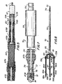
catheter 10 has placed, externally along a portion of its length, acylindrical braid electrode 42. Electrical connection toelectrode 42 is made by collapsing the portion of the braid not used aselectrode 42 into a rope, and passing the rope through a small opening into the large lumen. This rope conductor extends into an insulatingtube 48 having a first end terminating inhub 32 and a second end terminating in adefibrillator connector 50.Connector 50 has aconnection pin 52 extending therefrom.Connection pin 52 is electrically connected to the end of the rope conductor. - Referring to FIG. 2, a permanent bipolar catheter 11 is illustrated. An active fixation device such as a
helical spring 18 is normally received withintip assembly 12.Helical spring 18 may be extended to protrude fromtip assembly 12 when an appropriate activating member or stylet (not shown) disposed inlumen 20 of an inner insulatingtube 22 engages aslot 23 in a rotationally supported drivingmember 25, and is rotated, as is well known in the art. Awire coil conductor 24 extends longitudinally withintube 22 to electrically connecttip electrode 14 with a suitable connector (not shown) similar toconnector 26 of FIG. 1. A nine centimeter length ofSilastic® tube 38 is placed overinner tube 22. The inner diameter oftube 38 is sized so as to have a tight fit when adhered overinner tube 22, while the outer diameter is selected to be approximately that oftip assembly 12.Tube 38 has a double conical taper atdistal end 40A; that is, the outer diameter tapers inwardly and the inner diameter tapers outwardly. There is acircumferential space 41 of substantially triangular cross section between the most distal portion oftube 38 andinner tube 22.Tube 38 has a simple conical taper of its outer diameter atproximal end 40B.Inner tube 22 andSilastic® tube 38 are surrounded by a cylindrical braid 42 (FIG. 3).Braid 42 has adistal portion 43 with a diameter which fits snugly overtube 38. The mostdistal portion 45 ofbraid 42 is folded intospace 41 between the outer surface ofinner tube 22 and the tapered inner surface oftube 38. After this is done,tip assembly 12 is crimped to the distal end ofinner tube 22 atcrimp region 49. - A
Silastic® sleeve 51 is then placed over a portion ofcrimp region 49 and the distal end oftube 38 to insulate the proximal shank of the pacingelectrode 14 and to isolate the ends of the braided wires from the patient's body.Sleeve 51 has a maincylindrical portion 51A with an internal diameter that fits tightly aroundinner tube 22.Cylindrical portion 51A tapers at its distal end to a second cylindrical portion 51B which fits tightly around a proximal portion ofcrimp region 49. A third proximalcylindrical portion 51C ofsleeve 51 fits tightly around the distal portion ofbraid 42. Prior to placement ofsleeve 51. Dow Corning medical adhesive is applied to the portion ofbraid 42 which is surrounded bycylindrical portion 51C ofsleeve 51. - A reduced diameter
proximal portion 47 ofbraid 42 surroundsinner tube 22. The diameter of theproximal portion 47 ofbraid 42 is selected so that it fits snugly aboutinner tube 22. - A catheter in accordance with the invention may be terminated in various ways, as is well known in the art. If
braid 42 is to be terminated in a bifurcated manner, as illustrated with respect to FIG. 1,inner tube 22 may be removed from the braid approximately nine centimeters from its proximal end. The remaining portion ofbraid 42 is then inserted into insulatingtube 48 and electrically connected toconnection pin 52. - If a linear termination (not shown) for
braid 42, rather than a bifurcated termination, is desired, it is necessary that the proximal portion ofbraid 42 surroundstubes 22 along virtually its entire length. A terminal pin is used for the conductor associated with the tip electrode. A terminal ring may be used to terminate the braid. - A polyurethane
outer tube 54 is placed overbraid 42 and positioned so that its distal end is adjacent to the proximal end of theSilastic® tube 38, withbraid 42 passing between the adjacent ends ofouter tube 54 andtube 38. A moldedsleeve 56 formed of polyurethane is placed over the transition region.Sleeve 56 has a first substantiallycylindrical portion 56A which internally tapers at 56B to aproximal portion 56C having a cylindrical inner surface. The outer surface ofproximal portion 56C tapers in the proximal direction until its diameter is substantially that ofouter tube 54.Sleeve 56 is secured with Dow Corning medical adhesive which is applied to its inner surface prior to placement oncatheter 10. - Thus, between
sleeve 51 andsleeve 56 the wire braid electrode is exposed over a longitudinal distance of approximately 6 cm and available to deliver a cardioverting or defibrillation shock. The favorable results achieved with this design are discussed in greater detail below. - In the design illustrated in FIG. 2 the braid is used as both a conductor and an electrode. While a separate conducting wire may be welded to the braid, using the braid as both conductor and electrode simplifies fabrication and favorably resolves difficulties which might otherwise arise due to corrosion.
- Referring to FIG. 3,
braid 42 is comprised of sixteen titanium wires having a diameter of 0.003 inches (0.076 mm) wound at forty eight picks per inch to define a helix angle of approximately 40 degrees. Eight of the wires are wound in a first direction and the other eight are wound in a second direction. Preferably an electroplated platinum coating is formed over the titanium surface of the wires. Alternatively, the wires may be formed of a platinumiridium alloy.Braid 42 is tapered at 53 so that it follows the outer contour ofsleeve 38 and is annealed prior to assembly to reduce stress and provide the greatest possible longevity. - Referring to FIG. 4, an atrial temporary braid
endocardial catheter 10A has a sphericalpacing tip electrode 14A formed of 316 stainless steel. Thering electrode 16A is formed of a 90% platinum 10% iridium alloy. Thebraid 42A is formed of titanium and, as is the case for the embodiments illustrated in FIG. 1 and FIG. 2, continues from the 6 centimeter long braid electrode to serve as the conductor. The pacing and sensingterminal pins connector 26A similar toconnector 26, are formed of brass and gold plated. The tubes of the catheter body are formed from Ducor polyurethane. - The pacing and
sensing electrodes pin 52A which is connected to the defibrillator output, similar to pin 52, is formed of titanium. - FIG. 5 illustrates a preferred construction for a permanent tripolar braid
electrode defibrillation catheter 60. The construction is similar to that of a bipolar pacing catheter having anactive fixation member 18, aporous tip electrode 61 and ananode band 62. Disposed in the lumen of afirst polyurethane tube 63A is aconductor 64A which extends to tipelectrode 61. Asecond conductor 64B surroundstube 63A and extends to anodeband 62.Conductor 64B is surrounded by a secondinsulating tube 63B which extends toanode band 62. Acylindrical braid electrode 65 extends along a portion of the length ofcatheter 60 but is surrounded, at all except for its most distal 6 centimeters, by a polyurethane tube 63C which serves to insulate the unexposed portions ofbraid electrode 65 from the body. Tightly fitting and adheredelastic tubing sleeves 67A and 67B provide smooth transitions between components of different diameters. - Electrical connections at the proximal end of
catheter 60 may be made in a manner similar to that illustrated for temporarytripolar catheter 10 of FIG. 1. - All of the endocardial catheters using a braid electrode are advantageous in that they provide a very large surface area for the application of an electrical shock but do not abraid the cardiac tissue. Fibrotic tissue growth on and between the wires of the braid occurs. While such tissue growth tends to minimize any abrasiveness that might otherwise result from the geometry of the braid, it has been found that it does not interfere with the efficient delivery of a defribillation shock, i.e., it does not raise the defibrillation threshold.
- Referring to FIG. 6, a
subcutaneous patch electrode 90 having an insulated back 92 and an active facewire mesh electrode 94 is illustrated. An insu latedelectrical conductor 96 extends frompatch electrode 90 and terminates at a defibrillation connector (not shown) similar toconnector 50 and having a titanium pin similar to pin 52 extending therefrom. - A defibrillation system in accordance with the invention may use one or more catheters having a braid electrode. When two catheters are used, one is a ventricular catheter and the other an atrial catheter. These catheters may be used alone or in conjunction with one or two subcutaneous electrodes.
- FIG. 7 illustrates an embodiment of the invention which is most useful as a subcutaneous electrode to be used in conjunction with an endocardial lead having a braid electrode according to the invention. A lead 70 includes an
inner tube 72 surrounded by abraid 74. Asmall length 76 of the most distal portion ofbraid 74 surrounds the distal end oftube 72.Length 76 is forced into lumen 78 oftube 72. Lead 70 is terminated at its most distal end by aSilastic® cap 80, having a domed or spherical shape.Silastic® cap 80 having acylindrical portion 81 which extends intoinner tube 72, is secured in place with a suitable medical adhesive of the type described above. Anouter tube 82 of an insulating material such as Silastic® or polyurethane covers most of the length of lead 70, leaving only a length of approximate 9 cm ofbraid 74 exposed. Tightly fitting and adheredelastic tubing sleeves conventional connector 84 having an electrically conductingpin 86, as is well known in the art. - Lead 70 of FIG. 7 is especially advantageous for use subcutaneously at a portion of the thorax adjacent the heart. It is particularly advantageous in that only a small surgical incision in the skin is neces sary for placement of the lead. Preferably the exposed portion of
braid 74 is located in one of the intercostal spaces and is therefore less likely to produce complications in those patients of low weight. However, where appropriate, the exposed portion ofbraid 74 may be placed over a rib. Defibrillation threshold energy does not appear to vary significantly between placement in an intercostal space and placement over a rib. The braid is secured in place by suturing to the musculature. If deemed advantageous, a plurality of these single electrode leads may be utilized in a particular patient. - Referring to FIG. 8, another embodiment, a lead 90 in accordance with the invention, which can be utilized subcutaneously, is illustrated. An
inner tube 92 formed of a Silastic® or polyurethane material is surrounded by abraid 94 and extends to adistal end 96 to form afinger 97.Inner tube 92 andbraid 94 are terminated by aSilastic® cap 98 in a manner identical to the termination of lead 70 of FIG. 7. An outer insulating tube 100 formed of polyurethane or Silastic® fits snugly about the proximal portion ofbraid 94. - The proximal ends of each of two
braids sleeve 102, which is fitted snugly aboutbraid 94.Braids distal end 96 to connectingsleeve 102. Brazing is used so as to mechanically and electrically connectbraid 94,sleeve 102,braid 104A and braid 104B. -
Respective tubes inner tube 92, and having a length somewhat shorter than the distance fromdistal end 96 to connectingsleeve 102, are fitted withinbraids fingers finger 97. - The distal ends of
fingers caps 108A and 108B, respectively, in the same manner as lead 70 of FIG.7. A portion of thelead 90, including thedistal end 110 of outer tube 100, extends distally to aregion 105. Collapsed portions ofbraids tubes fingers trifurcation member 114. - It is intended that
fingers fingers - In a preferred method of use, a first tripolar catheter, e.g., the
catheter 60 of FIG. 5, is placed with a tip in the right ventricular apex (RVA). Thebraid electrode 42 and tip andring electrodes - Preferably a second catheter is placed in the right atrium so that its braid electrode is located in the high right atrium or in the superior vena cava (SVC). The second catheter may be of a construction identical to the first. Alternatively, the second catheter may be designed with a spacing between the ring and sleeve electrode which is different than in the first catheter. In addition the second catheter may be designed with a preformed "J" shape similar to that commonly used in certain atrial pacing catheters.
- In the atrium the tip and ring electrodes may be used for pacing and sensing in a variety of modes. These include dual chamber bradycardia pacing, atrial antitachycardia pacing and discrimination of ventricular tachycardia from supraventricular tachycardia or exercise tachycardia. The braid electrode of the second catheter may be used for cardioverting and defibrillating.
- According to the preferred method one or more subcutaneous electrodes is also used. These electrodes are placed outside the chest cavity but in proximity to the heart. The two catheter braid electrodes and one or two subcutaneous electrodes are connected in a selected combination for the application of cardioverting or defibrillating countershock. Various combinations of electrodes and countershocks have been described in the literature. These include single current pathways, simultaneous dual current pathways, sequential shocks and biphasic shocks.
- A second method of using the present invention utilizes one catheter according to the invention placed in the right ventricle and one or more subcutaneous electrodes. The electrode countershock is applied between the catheter braided sleeve electrode and the subcutaneous electrodes. Ventricular pacing and sensing is accomplished by using the bipolar tip and ring electrodes. Atrial sensing and pacing may be accomplished if a second, optional catheter of the type ordinarily used in bradycardia pacing is placed in the atrium.
- A third method utilizes one endocardial catheter according to the invention placed in the right atrium and one or more subcutaneous electrodes. A second catheter of the type ordinarily used in bradycardia pacing is placed in the right ventricle for sensing and pacing. Cardioverting or defibrillating countershocks are applied between the braided sleeve of the catheter and the subcutaneous electrodes.
- The current technique for implanting a non-thoracotomy defibrillation catheter system involves the following: First, the transvenous defibrillation catheter is implanted in the right ventricle (RV). Then, the thorax is "mapped" with an R2 electrode to optimize the position for the subcutaneous patch. Mapping requires that several defibrillation thresholds (DFTs) be found for various R2 placements using a temporary endocardial defibrillation catheter. The location of the R2 which offers the lowest DFT is where the subcutaneous patch electrode is placed. The catheters are then tunneled through the thorax and connected to the generator. The entire procedure is very time consuming and tedious to the patient.
- The above procedure may be further optimized if mapping and system implant take place on different days. This is most easily accomplished by using a temporary version of the catheter according to the invention, e.g., the
catheter 10 of FIG. 1, in conjunction with an R2 electrode for mapping. - In addition to defibrillation catheter system implants, a temporary catheter in accordance with the invention may also serve as a research tool for evaluating patients and catheter configurations as well as a routine electrophysiologic catheter to be used as a safeguard during procedures involving patients prone to ventricular or atrial fibrillation (VF or AF).
- For hospitalized or bedridden patients requiring defibrillation, an endocardial lead in accordance with the invention may be used with one or more cutaneous defibrillation electrodes. The energy required for defibrillation is reduced.
- Thus, it can be seen that the invention described above provides a number of improvements over the existing endocardial catheter and catheter and patch defibrillation electrode systems. In particular the braid electrode contributes very little stiffness to the catheter. The section of the catheter containing the braid electrode is nearly as flexible as the portion away from the braid and may be constructed so as to be of small diameter. For example, temporary versions of a lead according to the invention may have a size of 7 Fr or even smaller. The unit Fr indicates French guage and corresponds to three times the diameter of the lead in millimeters. Permanent versions may have a size of 8 Fr. Further, permanent versions of the catheter accept a stylet which can be used to temporarily stiffen and shape the catheter to facilitate implantation. In addition, the presence of the multiconductor braid provides a large surface area with a multitude of high field intensity points which facilitates effective defibrillation and provides a reasonably low defibrillation threshold. A braid electrode may also be used for pacing, with a relatively small area flexible braid electrode replacing a relatively large area, stiff band electrode. Finally, the multiconductor braid is inherently "failure tolerant" in that there are multiple electrical conduction paths. Thus a break in one or even several of the braid wires would not result in a failure of the lead.
- Although the invention has been described with reference to specific embodiments, it is to be understood that these embodiments are merely illustrative of the application of the principles of the invention. Numerous modifications may be made therein and other arrangements may be devised without departing from the spirit and scope of the invention.
Claims (26)
an elongate tubular insulating member;
a first exposed portion of electrically conductive braid forming a closely fitting sheath around a portion of said insulating member;
a first electrical coupling means for coupling said device to said lead, said tubular insulating member having a part which extends distally with respect to said electrical coupling means from said braid;
an electrode on said part, said electrode being spaced apart from said braid;
a first electrically insulated connection means for electrically connecting said braid and said electrical coupling means;
a second electrical coupling means for electrically coupling said device to said lead; and
a second electrical connection means for electrically connecting said electrode to said second electrical coupling means.
an integral portion of said braid extending to said electrical coupling means; and,
a tubular insulating means extending from said electrical coupling means to said first portion of said electrically conductive braid.
an elongate member formed of an insulating material;
a first terminal means at one end of said elongate member for connection to a source of electricity;
a tubular braid electrode surrounding said elongate member along a portion of said catheter, said electrode being disposed externally on said elongate member;
first electrical connection means for connecting said braid electrode to said terminal means;
a tip electrode at an end of said insulating member most distal from said first terminal means;
a second terminal means; and,
a second electrical connection means for connecting said tip electrode to said second terminal means.
a ring electrode surrounding said insulating member proximate said tip electrode;
a third terminal means; and,
a third electrical connection means for connecting said ring electrode to said third terminal means.
a patch electrode adapted for subcutaneous implantation in proximity to the heart:
fourth electrical connection means having a first end connected to said subcutaneous patch elec trode and a second end; and,
a fourth terminal means connected to said second end of said fourth electrical connection means.
an elongate tubular insulating material;
a first portion of.electrically conductive braid forming a closely fitting sheath around a portion of said insulating material;
an electrical coupling means for coupling said source to said lead; and,
electrically insulated connection means for electrically connecting said braid and said electrical coupling means.
an elongate member formed of an insulating material;
a first terminal means at one end of said elongate member for connection to a source of electricity;
a tubular braid electrode surrounding said elongate member along a portion of said catheter, said electrode being disposed externally on said elongate member;
first electrical connection means for connecting said braid electrode to said terminal means; and,
said subcutaneous lead comprising:
a plurality of electrically insulating elongate members;
for each of said elongate members, a respective tubular braid electrode surrounding one of said elongate members;
a mechanical connection means for mechan ically connecting said plurality of members,
an electrical coupling means for coupling said lead to said source of electrical energy; and,
an electrical connection means for electrically connecting said braid electrodes to one another and to said electrical coupling means.
a plurality of electrically insulating elongate members;
for each of said elongate members, a respective tubular braid electrode surrounding one of said elongate members;
a mechanical connection means for mechanically connecting said plurality of members,
an electrical coupling means for coupling said lead to said source of electrical energy; and
an electrical connection means for electrically connecting said braid electrodes to one another and to said electrical coupling means.
implanting an endocardial catheter having an exposed braid electrode along a portion of its length in the patent's heart;
providing a lead having an additional electrode along a portion of its length, said electrode being positioned so that current can flow through the patient between said braid electrode and said additional electrode; and,
electrically connecting said braid electrode and said additional electrode to a source of electrical stimulation energy.
Applications Claiming Priority (2)
| Application Number | Priority Date | Filing Date | Title |
|---|---|---|---|
| US434246 | 1989-11-13 | ||
| US07/434,246 US5005587A (en) | 1989-11-13 | 1989-11-13 | Braid Electrode leads and catheters and methods for using the same |
Publications (3)
| Publication Number | Publication Date |
|---|---|
| EP0428279A2 true EP0428279A2 (en) | 1991-05-22 |
| EP0428279A3 EP0428279A3 (en) | 1992-08-05 |
| EP0428279B1 EP0428279B1 (en) | 1997-01-02 |
Family
ID=23723445
Family Applications (1)
| Application Number | Title | Priority Date | Filing Date |
|---|---|---|---|
| EP90311565A Expired - Lifetime EP0428279B1 (en) | 1989-11-13 | 1990-10-22 | Braid electrode leads and catheters for using the same |
Country Status (6)
| Country | Link |
|---|---|
| US (1) | US5005587A (en) |
| EP (1) | EP0428279B1 (en) |
| JP (1) | JPH03170171A (en) |
| AU (1) | AU630842B2 (en) |
| CA (1) | CA2029136A1 (en) |
| DE (1) | DE69029564T2 (en) |
Cited By (11)
| Publication number | Priority date | Publication date | Assignee | Title |
|---|---|---|---|---|
| EP0460324A2 (en) * | 1990-06-06 | 1991-12-11 | Cardiac Pacemakers, Inc. | Subcutaneous defibrillation electrodes |
| EP0769308A1 (en) * | 1995-10-17 | 1997-04-23 | Pacesetter, Inc. | Implantable pacemaker lead |
| NL1005859C2 (en) * | 1997-04-21 | 1998-10-22 | Cordis Europ | Improved screened catheter for use with magnetic resonance imaging |
| WO2002087437A1 (en) * | 2001-04-27 | 2002-11-07 | C.R. Bard, Inc. | Catheter for three dimensional mapping of electrical activity in blood vessels and ablation procedure |
| WO2003035173A1 (en) * | 2001-10-22 | 2003-05-01 | Oscor Inc. | Adapter for electrical stimulation leads |
| US6616655B1 (en) | 1999-06-03 | 2003-09-09 | C. R. Bard, Inc. | Method and apparatus for performing cardiac ablations |
| US7270568B2 (en) | 2001-10-22 | 2007-09-18 | Oscor Inc. | Adapter for electrical stimulation leads |
| US7306594B2 (en) | 2000-05-03 | 2007-12-11 | C.R. Bard, Inc. | Apparatus and methods for mapping and ablation in electrophysiology procedures |
| US7727229B2 (en) | 2001-05-01 | 2010-06-01 | C.R. Bard, Inc. | Method and apparatus for altering conduction properties in the heart and in adjacent vessels |
| US7904161B2 (en) | 2001-10-22 | 2011-03-08 | Oscor Inc. | Lead adaptor having low resistance conductors and/or encapsulated housing |
| US8249685B2 (en) | 2004-05-17 | 2012-08-21 | C.R. Bard, Inc. | Method and apparatus for mapping and/or ablation of cardiac tissue |
Families Citing this family (102)
| Publication number | Priority date | Publication date | Assignee | Title |
|---|---|---|---|---|
| US5181526A (en) * | 1990-04-20 | 1993-01-26 | Tanaka Kikinzoku Kogyo K.K. | Electrode for human heart pacemaker |
| US5230337A (en) * | 1990-06-06 | 1993-07-27 | Cardiac Pacemakers, Inc. | Process for implanting subcutaneous defibrillation electrodes |
| US5209229A (en) * | 1991-05-20 | 1993-05-11 | Telectronics Pacing Systems, Inc. | Apparatus and method employing plural electrode configurations for cardioversion of atrial fibrillation in an arrhythmia control system |
| US5300106A (en) * | 1991-06-07 | 1994-04-05 | Cardiac Pacemakers, Inc. | Insertion and tunneling tool for a subcutaneous wire patch electrode |
| US5324326A (en) * | 1991-11-25 | 1994-06-28 | Telectronics Pacing Systems, Inc. | Pressure sensing pacing lead |
| SE9201600L (en) * | 1992-05-21 | 1993-11-22 | Siemens Elema Ab | The electrode device |
| DE4223152C1 (en) * | 1992-07-14 | 1993-10-21 | Sanol Arznei Schwarz Gmbh | Device and method for producing a micro connector element and electrical supply line with at least one micro connector element |
| US5311866A (en) * | 1992-09-23 | 1994-05-17 | Endocardial Therapeutics, Inc. | Heart mapping catheter |
| US7930012B2 (en) * | 1992-09-23 | 2011-04-19 | St. Jude Medical, Atrial Fibrillation Division, Inc. | Chamber location method |
| CA2144973C (en) * | 1992-09-23 | 2010-02-09 | Graydon Ernest Beatty | Endocardial mapping system |
| US5336254A (en) * | 1992-09-23 | 1994-08-09 | Medtronic, Inc. | Defibrillation lead employing electrodes fabricated from woven carbon fibers |
| US6240307B1 (en) | 1993-09-23 | 2001-05-29 | Endocardial Solutions, Inc. | Endocardial mapping system |
| US7189208B1 (en) * | 1992-09-23 | 2007-03-13 | Endocardial Solutions, Inc. | Method for measuring heart electrophysiology |
| AU5295493A (en) * | 1992-10-01 | 1994-04-26 | Cardiac Pacemakers, Inc. | Stent-type defibrillation electrode structures |
| CA2109980A1 (en) * | 1992-12-01 | 1994-06-02 | Mir A. Imran | Steerable catheter with adjustable bend location and/or radius and method |
| US5366496A (en) * | 1993-04-01 | 1994-11-22 | Cardiac Pacemakers, Inc. | Subcutaneous shunted coil electrode |
| US5562619A (en) * | 1993-08-19 | 1996-10-08 | Boston Scientific Corporation | Deflectable catheter |
| DE69433213T2 (en) * | 1993-11-10 | 2004-05-06 | Medtronic, Inc., Minneapolis | Catheter with electrode arrangement |
| EP0744977B1 (en) * | 1993-11-12 | 2003-03-26 | Micro Interventional Systems | Small diameter, high torque catheter |
| US6099524A (en) * | 1994-01-28 | 2000-08-08 | Cardiac Pacemakers, Inc. | Electrophysiological mapping and ablation catheter and method |
| ITRM940130A1 (en) * | 1994-03-10 | 1995-09-11 | P A & M Spa | SAFETY ELEMENT TO GUARANTEE THE ELECTRICAL RELIABILITY OF THE ELECTRODOCATHETERS FOR THE ELECTRIC STIMULATION OF THE |
| US5533985A (en) * | 1994-04-20 | 1996-07-09 | Wang; James C. | Tubing |
| US5549642A (en) * | 1994-08-19 | 1996-08-27 | Medtronic, Inc. | Atrial defibrillator and method of use |
| US5527351A (en) * | 1994-09-21 | 1996-06-18 | Friedman; Mark H. | Treatment of vascular and tension headache atypical facial pain allergic rhinitis and cervical muscle hyperactivity |
| SE9403279D0 (en) * | 1994-09-29 | 1994-09-29 | Siemens Elema Ab | The electrode device |
| EP0715865A2 (en) | 1994-12-09 | 1996-06-12 | Telectronics N.V. | Steerable stylet assembly |
| EP0792122A4 (en) | 1995-08-25 | 1999-04-07 | Rhythm Technologies Inc | Catheter |
| US5683444A (en) * | 1995-12-11 | 1997-11-04 | Huntley; Steve | Composite electrode |
| US6103037A (en) * | 1995-12-12 | 2000-08-15 | Medi-Dyne Inc. | Method for making a catheter having overlapping welds |
| US5772641A (en) * | 1995-12-12 | 1998-06-30 | Medi-Dyne Inc. | Overlapping welds for catheter constructions |
| US5951929A (en) * | 1995-12-12 | 1999-09-14 | Medi-Dyne Inc. | Method for forming a catheter having overlapping welds |
| US5690686A (en) * | 1996-04-30 | 1997-11-25 | Medtronic, Inc. | Atrial defibrillation method |
| US5824026A (en) * | 1996-06-12 | 1998-10-20 | The Spectranetics Corporation | Catheter for delivery of electric energy and a process for manufacturing same |
| US5810887A (en) * | 1996-08-23 | 1998-09-22 | Rhythm Technologies, Inc. | Temporary catheter |
| US5919222A (en) * | 1998-01-06 | 1999-07-06 | Medtronic Inc. | Adjustable medical electrode lead |
| US5928277A (en) * | 1998-02-19 | 1999-07-27 | Medtronic, Inc. | One piece defibrillation lead circuit |
| US7263397B2 (en) | 1998-06-30 | 2007-08-28 | St. Jude Medical, Atrial Fibrillation Division, Inc. | Method and apparatus for catheter navigation and location and mapping in the heart |
| US7670297B1 (en) | 1998-06-30 | 2010-03-02 | St. Jude Medical, Atrial Fibrillation Division, Inc. | Chamber mapping system |
| US7806829B2 (en) | 1998-06-30 | 2010-10-05 | St. Jude Medical, Atrial Fibrillation Division, Inc. | System and method for navigating an ultrasound catheter to image a beating heart |
| US20050004642A1 (en) * | 1998-11-09 | 2005-01-06 | Medtronic, Inc. | Implantable medical lead including overlay |
| US6445958B1 (en) | 1999-04-15 | 2002-09-03 | Intermedics, Inc. | Steerable coronary sinus defibrillation lead |
| US20010025192A1 (en) * | 1999-04-29 | 2001-09-27 | Medtronic, Inc. | Single and multi-polar implantable lead for sacral nerve electrical stimulation |
| US6611720B2 (en) | 1999-08-12 | 2003-08-26 | Irvine Biomedical Inc. | High torque catheter possessing multi-directional deflectability and methods thereof |
| US7171275B2 (en) | 1999-08-12 | 2007-01-30 | Irvine Biomedical Inc. | High torque balloon catheter possessing multi-directional deflectability and methods thereof |
| US6246914B1 (en) | 1999-08-12 | 2001-06-12 | Irvine Biomedical, Inc. | High torque catheter and methods thereof |
| US6408213B1 (en) * | 1999-09-29 | 2002-06-18 | Cardiac Pacemakers, Inc. | Low profile, ventricular, transvenous, epicardial defibrillation lead |
| CA2412295C (en) | 2000-07-14 | 2009-10-06 | Cook Incorporated | Medical device with braid and coil |
| JP2004513752A (en) * | 2000-11-22 | 2004-05-13 | メドトロニック,インコーポレイテッド | Apparatus for detecting and treating ventricular arrhythmias |
| US6606522B2 (en) | 2001-05-30 | 2003-08-12 | Cardiac Pacemakers, Inc. | Torque mechanism and method for endocardial leads |
| US6701191B2 (en) | 2001-05-30 | 2004-03-02 | Cardiac Pacemakers, Inc. | Lead having composite tubing |
| US7257449B2 (en) * | 2001-05-30 | 2007-08-14 | Cardiac Pacemakers, Inc. | Extendable/retractable lead having downsized lead body |
| ITPI20020047A1 (en) * | 2002-08-23 | 2002-11-21 | Intertech Di Giovanni Mastroma | "SHAPED SUPPORT FOR SHOES" |
| US7130700B2 (en) * | 2002-11-19 | 2006-10-31 | Medtronic, Inc. | Multilumen body for an implantable medical device |
| US7493175B2 (en) * | 2003-04-11 | 2009-02-17 | Cardiac Pacemakers, Inc. | Subcutaneous lead with tined fixation |
| US20040230282A1 (en) * | 2003-04-11 | 2004-11-18 | Cates Adam W. | Acute and chronic fixation for subcutaneous electrodes |
| US7499758B2 (en) | 2003-04-11 | 2009-03-03 | Cardiac Pacemakers, Inc. | Helical fixation elements for subcutaneous electrodes |
| US7517342B2 (en) * | 2003-04-29 | 2009-04-14 | Boston Scientific Scimed, Inc. | Polymer coated device for electrically medicated drug delivery |
| US8060207B2 (en) | 2003-12-22 | 2011-11-15 | Boston Scientific Scimed, Inc. | Method of intravascularly delivering stimulation leads into direct contact with tissue |
| US20050137646A1 (en) * | 2003-12-22 | 2005-06-23 | Scimed Life Systems, Inc. | Method of intravascularly delivering stimulation leads into brain |
| US7295875B2 (en) * | 2004-02-20 | 2007-11-13 | Boston Scientific Scimed, Inc. | Method of stimulating/sensing brain with combination of intravascularly and non-vascularly delivered leads |
| US7590454B2 (en) | 2004-03-12 | 2009-09-15 | Boston Scientific Neuromodulation Corporation | Modular stimulation lead network |
| US20050203600A1 (en) | 2004-03-12 | 2005-09-15 | Scimed Life Systems, Inc. | Collapsible/expandable tubular electrode leads |
| US7177702B2 (en) | 2004-03-12 | 2007-02-13 | Scimed Life Systems, Inc. | Collapsible/expandable electrode leads |
| US7844344B2 (en) | 2004-03-30 | 2010-11-30 | Medtronic, Inc. | MRI-safe implantable lead |
| US20050228469A1 (en) * | 2004-04-12 | 2005-10-13 | Cardiac Pacemakers, Inc. | Electrode and conductor interconnect and method therefor |
| US8412348B2 (en) | 2004-05-06 | 2013-04-02 | Boston Scientific Neuromodulation Corporation | Intravascular self-anchoring integrated tubular electrode body |
| US7286879B2 (en) | 2004-07-16 | 2007-10-23 | Boston Scientific Scimed, Inc. | Method of stimulating fastigium nucleus to treat neurological disorders |
| US7937160B2 (en) * | 2004-12-10 | 2011-05-03 | Boston Scientific Neuromodulation Corporation | Methods for delivering cortical electrode leads into patient's head |
| US20070162127A1 (en) * | 2005-12-08 | 2007-07-12 | Sdgi Holdings, Inc. | Instruments and techniques for delivering non-rigid implant members in surgical procedures |
| DE102006020363A1 (en) * | 2006-04-28 | 2007-10-31 | Gebr. Pajunk Besitzverwaltung Ohg | Catheter set for epidural or peripheral nerve block |
| US7684873B2 (en) * | 2006-10-31 | 2010-03-23 | Medtronic, Inc. | Implantable medical lead including a directional electrode and fixation elements along an interior surface |
| US8688238B2 (en) * | 2006-10-31 | 2014-04-01 | Medtronic, Inc. | Implantable medical elongated member including fixation elements along an interior surface |
| CA2877177C (en) | 2007-01-29 | 2018-05-22 | Simon Fraser University | Transvascular nerve stimulation apparatus and methods |
| US9044593B2 (en) | 2007-02-14 | 2015-06-02 | Medtronic, Inc. | Discontinuous conductive filler polymer-matrix composites for electromagnetic shielding |
| US8483842B2 (en) | 2007-04-25 | 2013-07-09 | Medtronic, Inc. | Lead or lead extension having a conductive body and conductive body contact |
| US8751018B1 (en) | 2007-05-08 | 2014-06-10 | Pacesetter Inc. | Implantable lead and method of making the same |
| US9037263B2 (en) | 2008-03-12 | 2015-05-19 | Medtronic, Inc. | System and method for implantable medical device lead shielding |
| EP2821097B1 (en) * | 2009-04-30 | 2017-10-04 | Medtronic Inc. | Termination of a shield within an implantable medical lead |
| EP2429651B1 (en) | 2009-04-30 | 2018-10-24 | Medtronic, Inc. | Detection of proper insertion of medical leads into a medical device |
| US8788061B2 (en) | 2009-04-30 | 2014-07-22 | Medtronic, Inc. | Termination of a shield within an implantable medical lead |
| US8224449B2 (en) * | 2009-06-29 | 2012-07-17 | Boston Scientific Neuromodulation Corporation | Microstimulator with flap electrodes |
| WO2012151396A2 (en) | 2011-05-03 | 2012-11-08 | Shifamed Holdings, Llc | Steerable delivery sheaths |
| EP4070850A1 (en) | 2012-03-05 | 2022-10-12 | Lungpacer Medical Inc. | Transvascular nerve stimulation apparatus and methods |
| US9463317B2 (en) | 2012-04-19 | 2016-10-11 | Medtronic, Inc. | Paired medical lead bodies with braided conductive shields having different physical parameter values |
| CA2877049C (en) | 2012-06-21 | 2022-08-16 | Simon Fraser University | Transvascular diaphragm pacing systems and methods of use |
| US9700224B2 (en) | 2013-03-14 | 2017-07-11 | C. R. Bard, Inc. | Electrically conductive pathway in a closed-ended catheter |
| CN105025830B (en) | 2013-03-14 | 2020-07-28 | C·R·巴德股份有限公司 | Closed catheter tip including conductive pathways |
| CN105873630B (en) | 2013-11-22 | 2020-01-03 | 隆佩瑟尔医疗公司 | Device and method for assisted respiration by transvascular nerve stimulation |
| US9993638B2 (en) | 2013-12-14 | 2018-06-12 | Medtronic, Inc. | Devices, systems and methods to reduce coupling of a shield and a conductor within an implantable medical lead |
| CA2935454A1 (en) | 2014-01-21 | 2015-07-30 | Simon Fraser University | Systems and related methods for optimization of multi-electrode nerve pacing |
| EP3171931B1 (en) | 2014-07-23 | 2021-11-10 | Medtronic, Inc. | Methods of shielding implantable medical leads and implantable medical lead extensions |
| US10155111B2 (en) | 2014-07-24 | 2018-12-18 | Medtronic, Inc. | Methods of shielding implantable medical leads and implantable medical lead extensions |
| WO2016160694A1 (en) * | 2015-03-27 | 2016-10-06 | Shifamed Holdings, Llc | Steerable medical devices, systems, and methods of use |
| CA2982823A1 (en) | 2015-04-24 | 2016-10-27 | Shifamed Holdings, Llc | Steerable medical devices, systems, and methods of use |
| CN108366715A (en) | 2015-11-09 | 2018-08-03 | 施菲姆德控股有限责任公司 | Steering assembly and application method for medical treatment device |
| US10293164B2 (en) | 2017-05-26 | 2019-05-21 | Lungpacer Medical Inc. | Apparatus and methods for assisted breathing by transvascular nerve stimulation |
| EP4115942A1 (en) | 2017-06-30 | 2023-01-11 | Lungpacer Medical Inc. | System for prevention, moderation, and/or treatment of cognitive injury |
| US10195429B1 (en) | 2017-08-02 | 2019-02-05 | Lungpacer Medical Inc. | Systems and methods for intravascular catheter positioning and/or nerve stimulation |
| US10940308B2 (en) | 2017-08-04 | 2021-03-09 | Lungpacer Medical Inc. | Systems and methods for trans-esophageal sympathetic ganglion recruitment |
| EP3877043A4 (en) | 2018-11-08 | 2022-08-24 | Lungpacer Medical Inc. | Stimulation systems and related user interfaces |
| WO2020232333A1 (en) | 2019-05-16 | 2020-11-19 | Lungpacer Medical Inc. | Systems and methods for sensing and stimulation |
| EP3983057A4 (en) | 2019-06-12 | 2023-07-12 | Lungpacer Medical Inc. | Circuitry for medical stimulation systems |
Citations (7)
| Publication number | Priority date | Publication date | Assignee | Title |
|---|---|---|---|---|
| EP0037223A1 (en) * | 1980-03-21 | 1981-10-07 | Medtronic, Inc. | A body implantable lead having a ring electrode, and a process for making same |
| US4295270A (en) * | 1979-10-15 | 1981-10-20 | Medtronic, Inc. | Electrode positioning system |
| US4444206A (en) * | 1982-04-29 | 1984-04-24 | Cordis Corporation | Mesh tip pacing lead assembly |
| US4481953A (en) * | 1981-11-12 | 1984-11-13 | Cordis Corporation | Endocardial lead having helically wound ribbon electrode |
| US4592372A (en) * | 1984-05-22 | 1986-06-03 | Cordis Corporation | Pacing/sensing electrode sleeve and method of forming same |
| EP0306442A2 (en) * | 1987-09-03 | 1989-03-08 | BIOTRONIK Mess- und Therapiegeräte GmbH & Co Ingenieurbüro Berlin | Implantation electrode for heart stimulation |
| US4940064A (en) * | 1986-11-14 | 1990-07-10 | Desai Jawahar M | Catheter for mapping and ablation and method therefor |
Family Cites Families (6)
| Publication number | Priority date | Publication date | Assignee | Title |
|---|---|---|---|---|
| US4033357A (en) * | 1975-02-07 | 1977-07-05 | Medtronic, Inc. | Non-fibrosing cardiac electrode |
| US4176660A (en) * | 1978-03-10 | 1979-12-04 | University Patents, Inc. | Disposable esophageal and tracheal multi-probes |
| US4402328A (en) * | 1981-04-28 | 1983-09-06 | Telectronics Pty. Limited | Crista terminalis atrial electrode lead |
| EP0165993A1 (en) * | 1983-12-27 | 1986-01-02 | The Board Of Trustees Of The Leland Stanford Junior University | Catheter for treatment of tumors and method for using same |
| US4641656A (en) * | 1985-06-20 | 1987-02-10 | Medtronic, Inc. | Cardioversion and defibrillation lead method |
| US4662377A (en) * | 1985-11-07 | 1987-05-05 | Mieczyslaw Mirowski | Cardioverting method and apparatus utilizing catheter and patch electrodes |
-
1989
- 1989-11-13 US US07/434,246 patent/US5005587A/en not_active Expired - Fee Related
-
1990
- 1990-10-22 DE DE69029564T patent/DE69029564T2/en not_active Expired - Fee Related
- 1990-10-22 EP EP90311565A patent/EP0428279B1/en not_active Expired - Lifetime
- 1990-10-24 AU AU64951/90A patent/AU630842B2/en not_active Ceased
- 1990-11-01 CA CA002029136A patent/CA2029136A1/en not_active Abandoned
- 1990-11-13 JP JP2304177A patent/JPH03170171A/en active Pending
Patent Citations (7)
| Publication number | Priority date | Publication date | Assignee | Title |
|---|---|---|---|---|
| US4295270A (en) * | 1979-10-15 | 1981-10-20 | Medtronic, Inc. | Electrode positioning system |
| EP0037223A1 (en) * | 1980-03-21 | 1981-10-07 | Medtronic, Inc. | A body implantable lead having a ring electrode, and a process for making same |
| US4481953A (en) * | 1981-11-12 | 1984-11-13 | Cordis Corporation | Endocardial lead having helically wound ribbon electrode |
| US4444206A (en) * | 1982-04-29 | 1984-04-24 | Cordis Corporation | Mesh tip pacing lead assembly |
| US4592372A (en) * | 1984-05-22 | 1986-06-03 | Cordis Corporation | Pacing/sensing electrode sleeve and method of forming same |
| US4940064A (en) * | 1986-11-14 | 1990-07-10 | Desai Jawahar M | Catheter for mapping and ablation and method therefor |
| EP0306442A2 (en) * | 1987-09-03 | 1989-03-08 | BIOTRONIK Mess- und Therapiegeräte GmbH & Co Ingenieurbüro Berlin | Implantation electrode for heart stimulation |
Cited By (19)
| Publication number | Priority date | Publication date | Assignee | Title |
|---|---|---|---|---|
| EP0460324A2 (en) * | 1990-06-06 | 1991-12-11 | Cardiac Pacemakers, Inc. | Subcutaneous defibrillation electrodes |
| EP0460324B1 (en) * | 1990-06-06 | 1996-03-20 | Cardiac Pacemakers, Inc. | Subcutaneous defibrillation electrodes |
| EP0769308A1 (en) * | 1995-10-17 | 1997-04-23 | Pacesetter, Inc. | Implantable pacemaker lead |
| NL1005859C2 (en) * | 1997-04-21 | 1998-10-22 | Cordis Europ | Improved screened catheter for use with magnetic resonance imaging |
| US6616655B1 (en) | 1999-06-03 | 2003-09-09 | C. R. Bard, Inc. | Method and apparatus for performing cardiac ablations |
| US9028486B2 (en) | 2000-05-03 | 2015-05-12 | Boston Scientific Scimed Inc. | Methods of using a catheter having a braided conductive member |
| US8157796B2 (en) | 2000-05-03 | 2012-04-17 | C.R. Bard, Inc. | Apparatus and methods for mapping and ablation in electrophysiology procedures |
| US7306594B2 (en) | 2000-05-03 | 2007-12-11 | C.R. Bard, Inc. | Apparatus and methods for mapping and ablation in electrophysiology procedures |
| US7255695B2 (en) | 2001-04-27 | 2007-08-14 | C.R. Bard, Inc. | Systems and methods for three-dimensional mapping of electrical activity |
| WO2002087437A1 (en) * | 2001-04-27 | 2002-11-07 | C.R. Bard, Inc. | Catheter for three dimensional mapping of electrical activity in blood vessels and ablation procedure |
| US7727229B2 (en) | 2001-05-01 | 2010-06-01 | C.R. Bard, Inc. | Method and apparatus for altering conduction properties in the heart and in adjacent vessels |
| US8951247B2 (en) | 2001-05-01 | 2015-02-10 | Boston Scientific Scimed, Inc. | Methods and apparatus for forming cardiac lesions and assessing lesion quality |
| US7270568B2 (en) | 2001-10-22 | 2007-09-18 | Oscor Inc. | Adapter for electrical stimulation leads |
| US7128600B2 (en) | 2001-10-22 | 2006-10-31 | Oscor Inc. | Adapter for electrical stimulation leads |
| US7904161B2 (en) | 2001-10-22 | 2011-03-08 | Oscor Inc. | Lead adaptor having low resistance conductors and/or encapsulated housing |
| US8145315B2 (en) | 2001-10-22 | 2012-03-27 | Oscor Inc | Lead adaptor having low resistance conductors and/or encapsulated housing |
| WO2003035173A1 (en) * | 2001-10-22 | 2003-05-01 | Oscor Inc. | Adapter for electrical stimulation leads |
| US8249685B2 (en) | 2004-05-17 | 2012-08-21 | C.R. Bard, Inc. | Method and apparatus for mapping and/or ablation of cardiac tissue |
| US8527027B2 (en) | 2004-05-17 | 2013-09-03 | C.R. Bard, Inc. | Method and apparatus for mapping and/or ablation of cardiac tissue |
Also Published As
| Publication number | Publication date |
|---|---|
| DE69029564D1 (en) | 1997-02-13 |
| AU6495190A (en) | 1991-05-16 |
| CA2029136A1 (en) | 1991-05-14 |
| EP0428279B1 (en) | 1997-01-02 |
| EP0428279A3 (en) | 1992-08-05 |
| DE69029564T2 (en) | 1997-06-05 |
| JPH03170171A (en) | 1991-07-23 |
| US5005587A (en) | 1991-04-09 |
| AU630842B2 (en) | 1992-11-05 |
Similar Documents
| Publication | Publication Date | Title |
|---|---|---|
| EP0428279B1 (en) | Braid electrode leads and catheters for using the same | |
| US4860769A (en) | Implantable defibrillation electrode | |
| US6684109B1 (en) | Endocardial lead | |
| US5405374A (en) | Transvenous defibrillation lead and method of use | |
| US5954761A (en) | Implantable endocardial lead assembly having a stent | |
| US5342414A (en) | Transvenous defibrillation lead | |
| US5800496A (en) | Medical electrical lead having a crush resistant lead body | |
| US7212870B1 (en) | Dual helix active fixation stimulation lead | |
| US7027852B2 (en) | Lead with distal tip surface electrodes connected in parallel | |
| US5609621A (en) | Right ventricular outflow tract defibrillation lead | |
| US6574514B2 (en) | System and assembly having conductive fixation features | |
| EP2092955B1 (en) | Leads for pacing and/or sensing the heart from within the coronary veins | |
| US4030508A (en) | Low output electrode for cardiac pacing | |
| AU650723B2 (en) | Transvenous defibrillation lead and method of use | |
| US5423865A (en) | Electrode system for a defibrillator | |
| AU629503B2 (en) | Transvenously placed defibrillation leads | |
| US6212434B1 (en) | Single pass lead system | |
| EP0979123B1 (en) | Intracardiac defibrillation system | |
| CA1081327A (en) | Bipolar body tissue electrode | |
| US5545205A (en) | Unitary intravascular defibrillating catheter with bipolar sensing | |
| US5713944A (en) | Cardioversion-defibrillation catheter lead having selectively exposable outer conductors | |
| CA2313174A1 (en) | Lead system |
Legal Events
| Date | Code | Title | Description |
|---|---|---|---|
| PUAI | Public reference made under article 153(3) epc to a published international application that has entered the european phase |
Free format text: ORIGINAL CODE: 0009012 |
|
| AK | Designated contracting states |
Kind code of ref document: A2 Designated state(s): DE FR GB IT NL SE |
|
| PUAL | Search report despatched |
Free format text: ORIGINAL CODE: 0009013 |
|
| AK | Designated contracting states |
Kind code of ref document: A3 Designated state(s): DE FR GB IT NL SE |
|
| 17P | Request for examination filed |
Effective date: 19921008 |
|
| 17Q | First examination report despatched |
Effective date: 19941114 |
|
| GRAG | Despatch of communication of intention to grant |
Free format text: ORIGINAL CODE: EPIDOS AGRA |
|
| GRAH | Despatch of communication of intention to grant a patent |
Free format text: ORIGINAL CODE: EPIDOS IGRA |
|
| GRAH | Despatch of communication of intention to grant a patent |
Free format text: ORIGINAL CODE: EPIDOS IGRA |
|
| GRAA | (expected) grant |
Free format text: ORIGINAL CODE: 0009210 |
|
| AK | Designated contracting states |
Kind code of ref document: B1 Designated state(s): DE FR GB IT NL SE |
|
| PG25 | Lapsed in a contracting state [announced via postgrant information from national office to epo] |
Ref country code: IT Free format text: LAPSE BECAUSE OF FAILURE TO SUBMIT A TRANSLATION OF THE DESCRIPTION OR TO PAY THE FEE WITHIN THE PRE;WARNING: LAPSES OF ITALIAN PATENTS WITH EFFECTIVE DATE BEFORE 2007 MAY HAVE OCCURRED AT ANY TIME BEFORE 2007. THE CORRECT EFFECTIVE DATE MAY BE DIFFERENT FROM THE ONE RECORDED.SCRIBED TIME-LIMIT Effective date: 19970102 Ref country code: NL Free format text: LAPSE BECAUSE OF FAILURE TO SUBMIT A TRANSLATION OF THE DESCRIPTION OR TO PAY THE FEE WITHIN THE PRESCRIBED TIME-LIMIT Effective date: 19970102 |
|
| REF | Corresponds to: |
Ref document number: 69029564 Country of ref document: DE Date of ref document: 19970213 |
|
| ET | Fr: translation filed | ||
| PG25 | Lapsed in a contracting state [announced via postgrant information from national office to epo] |
Ref country code: SE Effective date: 19970402 |
|
| NLV1 | Nl: lapsed or annulled due to failure to fulfill the requirements of art. 29p and 29m of the patents act | ||
| PGFP | Annual fee paid to national office [announced via postgrant information from national office to epo] |
Ref country code: GB Payment date: 19971013 Year of fee payment: 8 |
|
| PLBE | No opposition filed within time limit |
Free format text: ORIGINAL CODE: 0009261 |
|
| STAA | Information on the status of an ep patent application or granted ep patent |
Free format text: STATUS: NO OPPOSITION FILED WITHIN TIME LIMIT |
|
| 26N | No opposition filed | ||
| PGFP | Annual fee paid to national office [announced via postgrant information from national office to epo] |
Ref country code: FR Payment date: 19980930 Year of fee payment: 9 |
|
| PGFP | Annual fee paid to national office [announced via postgrant information from national office to epo] |
Ref country code: DE Payment date: 19981002 Year of fee payment: 9 |
|
| PG25 | Lapsed in a contracting state [announced via postgrant information from national office to epo] |
Ref country code: GB Free format text: LAPSE BECAUSE OF NON-PAYMENT OF DUE FEES Effective date: 19981022 |
|
| GBPC | Gb: european patent ceased through non-payment of renewal fee |
Effective date: 19981022 |
|
| PG25 | Lapsed in a contracting state [announced via postgrant information from national office to epo] |
Ref country code: FR Free format text: LAPSE BECAUSE OF NON-PAYMENT OF DUE FEES Effective date: 20000630 |
|
| PG25 | Lapsed in a contracting state [announced via postgrant information from national office to epo] |
Ref country code: DE Free format text: LAPSE BECAUSE OF NON-PAYMENT OF DUE FEES Effective date: 20000801 |
|
| REG | Reference to a national code |
Ref country code: FR Ref legal event code: ST |