EP0430542A2 - Method of producing flexible tube - Google Patents
Method of producing flexible tube Download PDFInfo
- Publication number
- EP0430542A2 EP0430542A2 EP90312622A EP90312622A EP0430542A2 EP 0430542 A2 EP0430542 A2 EP 0430542A2 EP 90312622 A EP90312622 A EP 90312622A EP 90312622 A EP90312622 A EP 90312622A EP 0430542 A2 EP0430542 A2 EP 0430542A2
- Authority
- EP
- European Patent Office
- Prior art keywords
- core member
- braid
- flex
- sheath
- resin layer
- Prior art date
- Legal status (The legal status is an assumption and is not a legal conclusion. Google has not performed a legal analysis and makes no representation as to the accuracy of the status listed.)
- Withdrawn
Links
Images

Classifications
-
- A—HUMAN NECESSITIES
- A61—MEDICAL OR VETERINARY SCIENCE; HYGIENE
- A61M—DEVICES FOR INTRODUCING MEDIA INTO, OR ONTO, THE BODY; DEVICES FOR TRANSDUCING BODY MEDIA OR FOR TAKING MEDIA FROM THE BODY; DEVICES FOR PRODUCING OR ENDING SLEEP OR STUPOR
- A61M25/00—Catheters; Hollow probes
- A61M25/0009—Making of catheters or other medical or surgical tubes
- A61M25/0012—Making of catheters or other medical or surgical tubes with embedded structures, e.g. coils, braids, meshes, strands or radiopaque coils
-
- A—HUMAN NECESSITIES
- A61—MEDICAL OR VETERINARY SCIENCE; HYGIENE
- A61B—DIAGNOSIS; SURGERY; IDENTIFICATION
- A61B1/00—Instruments for performing medical examinations of the interior of cavities or tubes of the body by visual or photographical inspection, e.g. endoscopes; Illuminating arrangements therefor
- A61B1/005—Flexible endoscopes
- A61B1/0051—Flexible endoscopes with controlled bending of insertion part
- A61B1/0055—Constructional details of insertion parts, e.g. vertebral elements
-
- B—PERFORMING OPERATIONS; TRANSPORTING
- B29—WORKING OF PLASTICS; WORKING OF SUBSTANCES IN A PLASTIC STATE IN GENERAL
- B29D—PRODUCING PARTICULAR ARTICLES FROM PLASTICS OR FROM SUBSTANCES IN A PLASTIC STATE
- B29D23/00—Producing tubular articles
- B29D23/001—Pipes; Pipe joints
-
- F—MECHANICAL ENGINEERING; LIGHTING; HEATING; WEAPONS; BLASTING
- F16—ENGINEERING ELEMENTS AND UNITS; GENERAL MEASURES FOR PRODUCING AND MAINTAINING EFFECTIVE FUNCTIONING OF MACHINES OR INSTALLATIONS; THERMAL INSULATION IN GENERAL
- F16L—PIPES; JOINTS OR FITTINGS FOR PIPES; SUPPORTS FOR PIPES, CABLES OR PROTECTIVE TUBING; MEANS FOR THERMAL INSULATION IN GENERAL
- F16L11/00—Hoses, i.e. flexible pipes
- F16L11/04—Hoses, i.e. flexible pipes made of rubber or flexible plastics
- F16L11/10—Hoses, i.e. flexible pipes made of rubber or flexible plastics with reinforcements not embedded in the wall
-
- A—HUMAN NECESSITIES
- A61—MEDICAL OR VETERINARY SCIENCE; HYGIENE
- A61M—DEVICES FOR INTRODUCING MEDIA INTO, OR ONTO, THE BODY; DEVICES FOR TRANSDUCING BODY MEDIA OR FOR TAKING MEDIA FROM THE BODY; DEVICES FOR PRODUCING OR ENDING SLEEP OR STUPOR
- A61M25/00—Catheters; Hollow probes
- A61M25/0043—Catheters; Hollow probes characterised by structural features
- A61M25/0045—Catheters; Hollow probes characterised by structural features multi-layered, e.g. coated
-
- A—HUMAN NECESSITIES
- A61—MEDICAL OR VETERINARY SCIENCE; HYGIENE
- A61M—DEVICES FOR INTRODUCING MEDIA INTO, OR ONTO, THE BODY; DEVICES FOR TRANSDUCING BODY MEDIA OR FOR TAKING MEDIA FROM THE BODY; DEVICES FOR PRODUCING OR ENDING SLEEP OR STUPOR
- A61M25/00—Catheters; Hollow probes
- A61M25/0043—Catheters; Hollow probes characterised by structural features
- A61M25/005—Catheters; Hollow probes characterised by structural features with embedded materials for reinforcement, e.g. wires, coils, braids
-
- B—PERFORMING OPERATIONS; TRANSPORTING
- B29—WORKING OF PLASTICS; WORKING OF SUBSTANCES IN A PLASTIC STATE IN GENERAL
- B29K—INDEXING SCHEME ASSOCIATED WITH SUBCLASSES B29B, B29C OR B29D, RELATING TO MOULDING MATERIALS OR TO MATERIALS FOR MOULDS, REINFORCEMENTS, FILLERS OR PREFORMED PARTS, e.g. INSERTS
- B29K2705/00—Use of metals, their alloys or their compounds, for preformed parts, e.g. for inserts
- B29K2705/08—Transition metals
-
- B—PERFORMING OPERATIONS; TRANSPORTING
- B29—WORKING OF PLASTICS; WORKING OF SUBSTANCES IN A PLASTIC STATE IN GENERAL
- B29L—INDEXING SCHEME ASSOCIATED WITH SUBCLASS B29C, RELATING TO PARTICULAR ARTICLES
- B29L2023/00—Tubular articles
- B29L2023/005—Hoses, i.e. flexible
- B29L2023/007—Medical tubes other than catheters
-
- B—PERFORMING OPERATIONS; TRANSPORTING
- B29—WORKING OF PLASTICS; WORKING OF SUBSTANCES IN A PLASTIC STATE IN GENERAL
- B29L—INDEXING SCHEME ASSOCIATED WITH SUBCLASS B29C, RELATING TO PARTICULAR ARTICLES
- B29L2031/00—Other particular articles
- B29L2031/753—Medical equipment; Accessories therefor
- B29L2031/7542—Catheters
Definitions
- This invention relates to a method of producing a flexible tube for use, for example, in an insertion portion of an endoscope or a catheter.
- a flexible tube used in an endoscope comprises a flex formed by winding a metal strip into a spiral shape, a braid provided around the outer periphery of the flex, and a resin layer formed on the outer periphery of the braid.
- the braid and the resin layer are joined together to form a sheath.
- the flex and the sheath are connected together only at their opposite ends.
- the above flexible tube is so flexible as to be bent.
- the flex resists a compressive force acting on the flexible tube in a radial direction of the flexible tube, thus preventing the flexible tube from being crushed flat.
- the braid resists a tensile force acting on the flexible tube in an axial direction of the flexible tube, and also resists a torsional force acting on the flexible tube. Thus, the braid prevents the elongation and torsion of the flexible tube.
- the resin layer resists a compressive force acting on the flexible tube in an axial direction of the flexible tube, thus preventing an axial contraction of the flexible tube.
- the resin layer also imparts liquid-sealing properties to the flexible tube.
- the braid and the resin layer reinforce each other. If the resin layer and the braid are separated from each other, wrinkles develop on the resin layer at an inner side of a bent portion of the flexible tube when the flexible tube is bent. Therefore, repeated bending of the flexible tube may cause the resin layer to be torn because of fatigue. Also, the braid may be cut because of fatigue. Therefore, the braid and the resin layer must be joined together firmly.
- the braid is fitted on the flex.
- an adhesive is coated on and impregnated in the braid.
- the resin layer is formed on the outer periphery of the braid either by fitting a heat-shrinkable tube on the braid or by extrusion of a resin.
- the adhesive layer is recognized as an inner resin layer.
- Another method without the use of an adhesive may be used in which the braid, fitted on the flex, is impregnated with a resin by dipping, and then the resin is dried to form the resin layer.
- the braid is embedded in the inside portion of the resin layer.
- the adhesive in order to meet the above first requirement (that is, the firm connection between the braid and the resin layer), the adhesive must be adequately penetrated into the braid. In this case, the adhesive reaches to the outer peripheral surface of the flex. As a result, each turn of the flex is adhesively bonded to the sheath, and therefore can not move relative to the sheath, thus failing to meet the above second requirement. In contrast, if the amount of impregnation of the adhesive in the braid is reduced in order to meet the second requirement, then the strength of bonding between the resin layer and the braid is decreased, thus failing to meet the first requirement.
- Japanese Laid-Open (Kokai) Patent Application No. 195538/83 discloses a technique in which a non-adhesive layer is formed on an outer peripheral surface of a flex, thereby preventing the flex from being adhesively bonded to a sheath even if an adhesive reaches the outer peripheral surface of the flex.
- this method however, part of the adhesive intrudes into the spaces between the adjacent turns of the flex, and then is solidified to form convex portions projecting radially inwardly. These convex portions prevent the turns of the flex from moving relative to the sheath.
- Japanese Laid-Open Patent Application No. 163330/83 discloses a method in which a resin layer is formed by extrusion.
- a molten resin intrudes into the spaces between turns of a flex, and then is solidified to form convex portions projecting radially inwardly. These convex portions prevent the turns of the flex from moving relative to a sheath.
- Japanese Laid-Open Patent Application No. 149124/84 discloses means for preventing an adhesive, penetrated into a braid, from reaching a flex. More specifically, a thin strip or band of a resin is wound on the outer periphery of the flex.
- Japanese Laid-Open Patent Application No. 137031/84 discloses a technique in which a thin tube is interposed between a flex and a braid. This tube prevents an adhesive from reaching the flex. In these cases, however, there is encountered a problem that upon repeated bending of the flexible tube, the strip or the tin tube may be ruptured or damaged by the frictional contact of the strip or the tin tube with the turns of the flex.
- Japanese Laid-Open Patent Application No. 230614/85 discloses a method in which an elongated core member of synthetic rubber is used.
- a flex is fitted on the outer periphery of the core member, and a braid is fitted on the outer periphery of the flex.
- the braid is impregnated with an adhesive, and a resin layer is formed on the outer periphery of the braid.
- part of the adhesive intrudes into the spaces between the turns of the flex, and then is solidified to form convex portions projecting radially inwardly.
- the height of these convex portions is generally equal to the thickness of the flex, and the convex portions prevent the turns of the flex from moving relative to a sheath.
- This prior patent application does not describe how the core member is removed from the sheath.
- Japanese Patent Publication No. 11011/88 discloses the prior art using an elongated core member.
- a braid is fitted on the core member.
- the braid is impregnated with an adhesive of a resin.
- a tube is fitted on the braid, and is heat-shrunk to be brought into intimate contact with the braid.
- the adhesive resin is compressed by the heat-shrunk tube, so that the adhesive resin is sufficiently introduced into the meshes of the braid and is cured to form an elastic resin layer.
- This method is to produce a flexible tube having no flex.
- This prior patent publication does not described how the core member is removed from the sheath.
- a method of producing a flexible tube comprising the steps of:
- a method of producing a flexible tube comprising the steps of:
- the endoscope comprises a body 1, an insertion portion 2 extending from one end of the body 1, a bending portion 3 extending from a distal end of the insertion portion 2, and a rigid portion 4 provided at a distal end of the bending portion 3.
- An ocular portion 5 is formed on the other end of the body 1, and is optically connected to an inspection window, formed on the rigid portion 4, via an optical fiber bundle and so on.
- a manipulation dial 6 for remote control of the bending portion 3 via wires is mounted on the peripheral wall of the body 1.
- a cable 7 is connected at one end to the body 1, and is connected at the other end to a light source. Light from the light source is fed to an illumination window, formed on the rigid portion 4, via an optical fiber bundle passing through the cable 7, the body 1, the insertion portion 2 and the bending portion 3, and the light is further emitted from the illumination window.
- the insertion portion 2 has a flexible tube 10 shown in Figs. 2 and 3.
- the above-mentioned optical fiber bundles, the wires and etc., are passed through the flexible tube 10.
- the flexible tube 10 comprises a flex 11 formed by winding a metal strip into a spiral shape, a braid 12 mounted around the outer periphery of the flex 11, a soft resin layer 13 mounted around the outer periphery of the braid 12.
- the braid 12 is embedded in an adhesive layer 14, and the braid 12 and the resin layer 13 are joined together through the adhesive layer 14.
- the braid 12, the resin layer 13 and the adhesive layer 14 jointly constitute a sheath 15 which is so flexible as to be bent.
- the adhesive layer 14 is made of an elastic resin, and can be recognized as an inner resin layer.
- the braid 12 is made of narrow wires of steel, copper, a copper alloy or the like.
- a lubricating layer 16 is formed on the outer peripheral surface of the flex 11.
- the outer diameter of the flex 11 in its natural condition is slightly greater than the inner diameter of the sheath 15, and therefore the flex 11 is held in contact with the inner peripheral surface of the sheath 15 with a slight resilient force.
- the sheath 15 has an inner diameter of 8 mm and an outer diameter of 9.4 mm.
- the thickness of the braid 12 is 0.2 mm, and the thickness of the adhesive layer 14 is almost the same as the thickness of the braid 12.
- the thickness of the resin layer 13 is 0.5 mm, and the thickness of the flex 11 is 0.2 mm, and the thickness of the lubricating layer 16 is 30 ⁇ m.
- a pair of rings 17 and 18 of metal are attached to the opposite ends of the flexible tube 10.
- Each of the rings 17 and 18 has an inner diameter slightly greater than that of the sheath 15, and has an outer diameter slightly smaller than that of the sheath 15.
- the opposite ends of the braid 12, as well as the opposite ends of the flex 11, project respectively from the opposite ends of the adhesive layer 14 and also project respectively from the opposite ends of the resin layer 13.
- the opposite ends of the braid 12 as well as the opposite ends of the flex 11 are soldered respectively to the inner peripheral surfaces of the rings 17 and 18.
- the ring 17 is received in the body 1 and fixed thereto, and the ring 18 is connected to the proximal end of the bending portion 3.
- Fig. 4 shows a modified flexible tube 10A.
- a resin layer 13A and a braid 12, which jointly constitute a sheath 15A of the flexible tube 10A, are directly joined together, with no adhesive layer interposed therebetween.
- the braid 12 is embedded in the inside portion of the resin layer 13.
- the other parts are the same as those of the flexible tube 10 of Fig. 3, and are designated by identical reference numerals, respectively, and therefore explanation of those corresponding parts is omitted.
- each of the flexible tubes 10 and 10A shown respectively in Figs. 3 and 4 is similar to a conventional construction.
- a method of producing the flexible tube 10 of Fig. 3 will now be described.
- a core member 20 in the form of a straight hollow cylindrical pipe.
- the core member 20 is made, for example, of a glass material which is dissolvable in an acid.
- the outer diameter of the core member 20 is slightly smaller than the outer diameter of the flex 11 in its natural condition.
- the opposite ends of the core member 20 are closed.
- the braid 12 is fitted on the core member 20, and then the braid 12 is wiped or rubbed by rollers to be brought into intimate contact with the outer peripheral surface of the core member 20. Then, the braid 12 is fastened at its opposite ends to the core member 20 by tapes or the like. Instead of using the rollers, the braid 20 may be pulled axially of the core member 20 to be brought into intimate contact with the core member 20.
- a hot-melt type adhesive in a liquid state is applied to the outer peripheral surface of the braid 12 by coating, spraying or the like, so that the adhesive is impregnated into the braid 12.
- the thus impregnated adhesive is solidified or set to form an adhesive layer, and the braid 12 is embedded in this adhesive layer.
- the adhesive layer is not formed on the opposite end portions of the braid 12.
- a heat-shrinkable tube 21 made, for example, of a polyurethane resin is fitted on the braid 12. Then, the tube 21 is heated to be shrunk radially, so that the tube 21 is intimately fitted on the braid 12. At this time, the adhesive layer is again melted by the heat applied to the tube 21, and bonds the tube 21 and the braid 12 together.
- the above adhesive is a polyester-type hot melt agent which can be relatively satisfactorily bonded adhesively to both the tube 21 of a polyurethane resin and the braid 12 of metal.
- the adhesive when cured or set, forms the adhesive layer 14 shown in Fig. 3, and the cured tube 21 serves as the resin layer 13. Thus, the sheath 15 is formed.
- the opposite end portions of the braid 12 do not have the adhesive layer, and therefore are not bonded to the tube 21.
- the closed opposite ends of the core member 20 is cut to be opened, and then the above sheath assembly is dipped in a dissolving solution 22 of an acid, so that the core member 20 is dissolved.
- the core member 20 has a pipe-shape, the core member 20 begins to be dissolved from its inner peripheral surface. This enhances the dissolving efficiency.
- the dissolving solution 22 is circulated in order to promote the dissolving of the core member 20.
- the dissolving solution 22 is of the type which dissolves only the core member 20 and does not dissolve the braid 12, the adhesive layer 14 and the resin layer 13.
- nitric acid is used as the dissolving solution.
- the core member 20 is in the form of a pipe so that the dissolving of the core member 20 can begin from its inner peripheral surface, it is particularly necessary that before the dissolving, foreign matters of a non-dissolving nature should not adhere to the inner peripheral surface of the core member 20. For this reason, in this embodiment, the opposite ends of the core member 20 are closed beforehand.
- the opposite end portions of the resin layer 13 which are not bonded to the braid 12 are cut so as to expose the opposite end portions of the braid 12.
- the flex 11 having the lubricating layer 16 preformed thereon is inserted into the sheath 15.
- the length of the flex 11 in its natural condition is substantially equal to the length of the braid 12.
- the insertion of the flex 11 into the sheath 15 will now be described in detail.
- a core member 30 having an outer diameter smaller than the inner diameter of the flex 11.
- the outer diameter of the core member 30 is smaller than the inner diameter of the sheath 15, and the difference between this outer diameter and this inner diameter is greater than the double of the thickness of the flex 11.
- the flex 11 is fitted on the core member 30, and is twisted into a smaller diameter, so that the flex 11 is brought into contact with the outer peripheral surface of the core member 30.
- This reduced-diameter flex 11 has a length generally equal to its length in its natural condition, and the pitch of the turns of the reduced-diameter flex 11 becomes smaller.
- the opposite ends of the flex 10 are fixed to the outer peripheral surface of the core member 30 by screws 31.
- the core member 30 with the flex 11 is inserted into the sheath 15.
- the fixing of the opposite ends of the flex 11 to the core member 30 is released by removing the screws 31, so that the flex 11 is increased in diameter to be brought into contact with the sheath 15 under a small pressure. In this manner, the flex 11 can be easily inserted into the sheath 15.
- the core member 30 is moved axially and is withdrawn from the flex 11 and the sheath 15.
- the opposite end portions of the braid 12 are soldered respectively to the outer peripheral surfaces of the opposite end portions of the flex 11, and the opposite end portions of the flex 11 as well as the opposite end portions of the braid 12 are soldered respectively to the rings 17 and 18 shown in Fig. 2.
- the flex 11 is inserted thereinto, and therefore the flex 11 is positively prevented from being bonded to the sheath 15 by the adhesive. Further, since the adhesive reaches the outer peripheral surface of the core member 20 and is cured there, the inner peripheral surface of the adhesive layer 14 is smooth. Therefore, the turns of the flex 11 can be smoothly moved relative to the sheath 15.
- the core member 20 Since the core member 20 is to be dissolved later, there is no need to form a layer of a non-adhesive nature on the outer peripheral surface of the core member 20. Therefore, the adhesive is allowed to be satisfactorily bonded to the core member 20, thereby forming a smoother surface.
- the lubricating layer 16 is formed on the outer peripheral surface of the flex 11. The lubricating layer 16 does not need to have the function of preventing the adhering of the adhesive thereto, and therefore the material for the lubricating layer 16 can be selected, only taking its frictional resistance into consideration. Therefore, the lubricating layer 16 can be made of a material having a very low frictional resistance.
- the lubricating layer 16 can be made of molybdenum disulfide or ceramics.
- the frictional resistance between the inner peripheral surface of the adhesive layer 14 (i.e., the inner peripheral surface of the sheath 15) and the flex 11 is very low, and therefore the turns of the flex 11 can be more smoothly moved relative to the sheath 15.
- the bending resistance of the flexible tube 10 can be reduced to a very small level.
- the adhesive When the adhesive is to be impregnated into the braid 12, it is not necessary at all to consider the adhering of the adhesive to the outer peripheral surface of the flex 11. Therefore, the adhesive can be sufficiently impregnated into the braid 12, and the strength of bonding between the braid 12 and the resin layer 13 can be increased. This prevents a premature rupture of the resin layer 13 which would otherwise be caused by the separation of the braid 12 from the resin layer 13 due to repeated bending of the flexible tube 10.
- the braid may be made solely of chemical fibers, or may be made of a combination of chemical fibers and metal wires.
- the core member to be inserted into the braid for assembling the sheath may be made of a glass material dissolvable in an alkali solution. Also, this core member may be made of any other suitable dissolvable material than a glass material.
- the core member to be inserted in the braid may be removed from the sheath by moving the core member axially relative to the sheath.
- the core member is in the form of a bar or a pipe made of stainless steel, brass, aluminum or the like.
- a layer of a non-adhesive nature is preferably preformed on the outer periphery of the core member. Examples of such non-adhesive material include PTFE (polytetrafluoroethylene) and FEP (tetrafluoroethylene-hexafluoropropylene copolymer).
- the following modified methods may be used for forming the resin layer. These method are similar to the above embodiment in that the braid is fitted on the core member, and the adhesive is impregnated in the braid and is cured to form the adhesive layer.
- a tube of a thermoplastic resin is heated and softened, and is increased in diameter by an air pressure.
- This tube is used instead of the heat-shrinkable tube of the above embodiment.
- the thus enlarged-diameter tube is fitted on the braid 2, and then the tube is heated at a temperature higher than the temperature of the heat used for the above diameter-increasing step, and then the tube is returned to its initial diameter to be brought into intimate contact with the braid. At this time, the braid and the tube are bonded together by the adhesive.
- a tube of a thermoplastic resin is fitted on the braid, and this tube is heated and softened, and in this condition pressure is applied to the outer peripheral surface of the tube by rollers or the like, thereby bringing the tube into intimate contact with the braid.
- a molten resin is applied to the outer peripheral surface of the braid by extrusion, and then the molten resin is cured to form the resin layer.
- a resin in a liquid state is applied to the braid by dipping, and then the resin is dried and cured to form the resin layer.
- the braid is embedded in the inside portion of the cured resin layer, thereby providing the flexible tube 10A shown in Fig.4.
- the braid 12 and the resin layer 13A can, of course, be firmly joined together.
- the inner peripheral surface of the resin layer 13A is smooth, and part of the resin layer 13A will not intrude into the spaces between the turns of the flex 11, thereby ensuring a smooth movement of the turns of the flex 11 relative to the sheath 15A.
- the dipping method it is necessary that at least one end of the glass pipe used as the core member should be closed so as to prevent the molten resin from intruding into the glass pipe.
- the methods in which the dissolvable core member is removed from the sheath by dissolving this core member can be used for producing the type of flexible tube having no flex.
Abstract
Description
- This invention relates to a method of producing a flexible tube for use, for example, in an insertion portion of an endoscope or a catheter.
- Generally, a flexible tube used in an endoscope comprises a flex formed by winding a metal strip into a spiral shape, a braid provided around the outer periphery of the flex, and a resin layer formed on the outer periphery of the braid. The braid and the resin layer are joined together to form a sheath. The flex and the sheath are connected together only at their opposite ends.
- The above flexible tube is so flexible as to be bent. The flex resists a compressive force acting on the flexible tube in a radial direction of the flexible tube, thus preventing the flexible tube from being crushed flat. The braid resists a tensile force acting on the flexible tube in an axial direction of the flexible tube, and also resists a torsional force acting on the flexible tube. Thus, the braid prevents the elongation and torsion of the flexible tube. The resin layer resists a compressive force acting on the flexible tube in an axial direction of the flexible tube, thus preventing an axial contraction of the flexible tube. The resin layer also imparts liquid-sealing properties to the flexible tube.
- In the above sheath, the braid and the resin layer reinforce each other. If the resin layer and the braid are separated from each other, wrinkles develop on the resin layer at an inner side of a bent portion of the flexible tube when the flexible tube is bent. Therefore, repeated bending of the flexible tube may cause the resin layer to be torn because of fatigue. Also, the braid may be cut because of fatigue. Therefore, the braid and the resin layer must be joined together firmly.
- On the other hand, when the flexible tube is bent, the interval or distance between any adjacent turns of the flex becomes greater at the outer side of the bent flexible tube, and becomes smaller at the inner side thereof. Therefore, in order to reduce the bending resistance of the flexible tube, it is necessary that each turn of the flex should be movable relative to the sheath.
- An ordinary conventional method of producing the above flexible tube will now be described. First, the braid is fitted on the flex. Then, an adhesive is coated on and impregnated in the braid. Then, the resin layer is formed on the outer periphery of the braid either by fitting a heat-shrinkable tube on the braid or by extrusion of a resin. In this case, the adhesive layer is recognized as an inner resin layer.
- Another method without the use of an adhesive may be used in which the braid, fitted on the flex, is impregnated with a resin by dipping, and then the resin is dried to form the resin layer. In this case, the braid is embedded in the inside portion of the resin layer.
- In the method using the adhesive, in order to meet the above first requirement (that is, the firm connection between the braid and the resin layer), the adhesive must be adequately penetrated into the braid. In this case, the adhesive reaches to the outer peripheral surface of the flex. As a result, each turn of the flex is adhesively bonded to the sheath, and therefore can not move relative to the sheath, thus failing to meet the above second requirement. In contrast, if the amount of impregnation of the adhesive in the braid is reduced in order to meet the second requirement, then the strength of bonding between the resin layer and the braid is decreased, thus failing to meet the first requirement.
- In the method without the use of an adhesive, when it is intended to adequately impregnate the liquid-state resin into the braid, part of this resin intrudes into the spaces between the turns of the flex, and then is solidified to form convex portions projecting radially inwardly, thus failing to meet the second requirement. In contrast, if the amount of impregnation of the resin into the braid is reduced in order to meet the second requirement, then the strength of connection between the braid and the resin is decreased, thus failing to meet the first requirement.
- Next, reference is now made to the prior art. Japanese Laid-Open (Kokai) Patent Application No. 195538/83 discloses a technique in which a non-adhesive layer is formed on an outer peripheral surface of a flex, thereby preventing the flex from being adhesively bonded to a sheath even if an adhesive reaches the outer peripheral surface of the flex. With this method, however, part of the adhesive intrudes into the spaces between the adjacent turns of the flex, and then is solidified to form convex portions projecting radially inwardly. These convex portions prevent the turns of the flex from moving relative to the sheath.
- Japanese Laid-Open Patent Application No. 163330/83 discloses a method in which a resin layer is formed by extrusion. In this method, where an adhesive is not used, a molten resin intrudes into the spaces between turns of a flex, and then is solidified to form convex portions projecting radially inwardly. These convex portions prevent the turns of the flex from moving relative to a sheath.
- Japanese Laid-Open Patent Application No. 149124/84 discloses means for preventing an adhesive, penetrated into a braid, from reaching a flex. More specifically, a thin strip or band of a resin is wound on the outer periphery of the flex. Japanese Laid-Open Patent Application No. 137031/84 discloses a technique in which a thin tube is interposed between a flex and a braid. This tube prevents an adhesive from reaching the flex. In these cases, however, there is encountered a problem that upon repeated bending of the flexible tube, the strip or the tin tube may be ruptured or damaged by the frictional contact of the strip or the tin tube with the turns of the flex.
- Japanese Laid-Open Patent Application No. 230614/85 discloses a method in which an elongated core member of synthetic rubber is used. A flex is fitted on the outer periphery of the core member, and a braid is fitted on the outer periphery of the flex. The braid is impregnated with an adhesive, and a resin layer is formed on the outer periphery of the braid. In this method, part of the adhesive intrudes into the spaces between the turns of the flex, and then is solidified to form convex portions projecting radially inwardly. The height of these convex portions is generally equal to the thickness of the flex, and the convex portions prevent the turns of the flex from moving relative to a sheath. This prior patent application does not describe how the core member is removed from the sheath.
- Japanese Patent Publication No. 11011/88 discloses the prior art using an elongated core member. A braid is fitted on the core member. The braid is impregnated with an adhesive of a resin. Further, a tube is fitted on the braid, and is heat-shrunk to be brought into intimate contact with the braid. The adhesive resin is compressed by the heat-shrunk tube, so that the adhesive resin is sufficiently introduced into the meshes of the braid and is cured to form an elastic resin layer. Thus, it is intended to obtain a sheath having a smooth inner peripheral surface. This method is to produce a flexible tube having no flex. This prior patent publication does not described how the core member is removed from the sheath.
- It is an object of this invention to provide a method of producing a flexible tube which is so flexible as to be easily bent, and has a high durability.
- According to one aspect of the present invention, there is provided a method of producing a flexible tube comprising the steps of:
- (a) fitting a braid on an outer periphery of an elongated core member of a cylindrical shape;
- (b) forming a soft resin layer on an outer periphery of the braid, and joining the resin layer and the braid together to form a sheath;
- (c) removing the core member from the sheath; and
- (d) subsequently inserting a flex into the sheath, the flex being in the form of a spirally-wound metal strip.
- According to another aspect of the invention, there is provided a method of producing a flexible tube comprising the steps of:
- (a) fitting a braid on an outer periphery of an elongated core member of a cylindrical shape, the core member being made of a dissolvable material;
- (b) forming a soft resin layer on an outer periphery of the braid, and joining the resin layer and the braid together to form a sheath; and
- (c) removing the core member from the sheath by dipping the core member in a dissolving solution.
-
- Fig. 1 is a side-elevational view of an endoscope incorporating a flexible tube provided in accordance with the present invention;
- Fig. 2 is a side-elevational view of the flexible tube;
- Fig. 3 is an enlarged cross-sectional view of a portion of the flexible tube;
- Fig. 4 is a view similar to Fig. 3, but showing a modified flexible tube; and
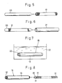
- Figs. 5 to 8 are views illustrative of the sequence of the formation of the flexible tube.
- Before describing a flexible tube-producing method of the present invention, an endoscope and a flexible tube used in the endoscope will first be described with reference to Figs. 1 to 4.
- As shown in Fig. 1, the endoscope comprises a body 1, an
insertion portion 2 extending from one end of the body 1, a bendingportion 3 extending from a distal end of theinsertion portion 2, and a rigid portion 4 provided at a distal end of the bendingportion 3. Anocular portion 5 is formed on the other end of the body 1, and is optically connected to an inspection window, formed on the rigid portion 4, via an optical fiber bundle and so on. A manipulation dial 6 for remote control of the bendingportion 3 via wires is mounted on the peripheral wall of the body 1. A cable 7 is connected at one end to the body 1, and is connected at the other end to a light source. Light from the light source is fed to an illumination window, formed on the rigid portion 4, via an optical fiber bundle passing through the cable 7, the body 1, theinsertion portion 2 and the bendingportion 3, and the light is further emitted from the illumination window. - The
insertion portion 2 has aflexible tube 10 shown in Figs. 2 and 3. The above-mentioned optical fiber bundles, the wires and etc., are passed through theflexible tube 10. - The
flexible tube 10 comprises aflex 11 formed by winding a metal strip into a spiral shape, abraid 12 mounted around the outer periphery of theflex 11, asoft resin layer 13 mounted around the outer periphery of thebraid 12. Thebraid 12 is embedded in anadhesive layer 14, and thebraid 12 and theresin layer 13 are joined together through theadhesive layer 14. Thebraid 12, theresin layer 13 and theadhesive layer 14 jointly constitute asheath 15 which is so flexible as to be bent. Theadhesive layer 14 is made of an elastic resin, and can be recognized as an inner resin layer. In this embodiment,thebraid 12 is made of narrow wires of steel, copper, a copper alloy or the like. Alubricating layer 16 is formed on the outer peripheral surface of theflex 11. The outer diameter of theflex 11 in its natural condition is slightly greater than the inner diameter of thesheath 15, and therefore theflex 11 is held in contact with the inner peripheral surface of thesheath 15 with a slight resilient force. - With respect to the dimensions of the
flexible tube 10 shown in Fig. 3, thesheath 15 has an inner diameter of 8 mm and an outer diameter of 9.4 mm. The thickness of thebraid 12 is 0.2 mm, and the thickness of theadhesive layer 14 is almost the same as the thickness of thebraid 12. The thickness of theresin layer 13 is 0.5 mm, and the thickness of theflex 11 is 0.2 mm, and the thickness of thelubricating layer 16 is 30 µm. - As shown in Fig. 2, a pair of
rings flexible tube 10. Each of therings sheath 15, and has an outer diameter slightly smaller than that of thesheath 15. The opposite ends of thebraid 12, as well as the opposite ends of theflex 11, project respectively from the opposite ends of theadhesive layer 14 and also project respectively from the opposite ends of theresin layer 13. The opposite ends of thebraid 12 as well as the opposite ends of theflex 11 are soldered respectively to the inner peripheral surfaces of therings ring 17 is received in the body 1 and fixed thereto, and thering 18 is connected to the proximal end of the bendingportion 3. - Fig. 4 shows a modified
flexible tube 10A. Aresin layer 13A and abraid 12, which jointly constitute asheath 15A of theflexible tube 10A, are directly joined together, with no adhesive layer interposed therebetween. Namely, thebraid 12 is embedded in the inside portion of theresin layer 13. The other parts are the same as those of theflexible tube 10 of Fig. 3, and are designated by identical reference numerals, respectively, and therefore explanation of those corresponding parts is omitted. - The basic construction of each of the
flexible tubes flexible tube 10 of Fig. 3 will now be described. As shown in Fig. 5, first, there is prepared acore member 20 in the form of a straight hollow cylindrical pipe. Thecore member 20 is made, for example, of a glass material which is dissolvable in an acid. The outer diameter of thecore member 20 is slightly smaller than the outer diameter of theflex 11 in its natural condition. The opposite ends of thecore member 20 are closed. - As shown in Fig.5, the
braid 12 is fitted on thecore member 20, and then thebraid 12 is wiped or rubbed by rollers to be brought into intimate contact with the outer peripheral surface of thecore member 20. Then, thebraid 12 is fastened at its opposite ends to thecore member 20 by tapes or the like. Instead of using the rollers, thebraid 20 may be pulled axially of thecore member 20 to be brought into intimate contact with thecore member 20. - Then, a hot-melt type adhesive in a liquid state is applied to the outer peripheral surface of the
braid 12 by coating, spraying or the like, so that the adhesive is impregnated into thebraid 12. The thus impregnated adhesive is solidified or set to form an adhesive layer, and thebraid 12 is embedded in this adhesive layer. The adhesive layer is not formed on the opposite end portions of thebraid 12. - Then, as shown in Fig. 6, a heat-
shrinkable tube 21 made, for example, of a polyurethane resin is fitted on thebraid 12. Then, thetube 21 is heated to be shrunk radially, so that thetube 21 is intimately fitted on thebraid 12. At this time, the adhesive layer is again melted by the heat applied to thetube 21, and bonds thetube 21 and thebraid 12 together. Preferably, the above adhesive is a polyester-type hot melt agent which can be relatively satisfactorily bonded adhesively to both thetube 21 of a polyurethane resin and thebraid 12 of metal. The adhesive, when cured or set, forms theadhesive layer 14 shown in Fig. 3, and the curedtube 21 serves as theresin layer 13. Thus, thesheath 15 is formed. The opposite end portions of thebraid 12 do not have the adhesive layer, and therefore are not bonded to thetube 21. - Then, as shown in Fig. 7, the closed opposite ends of the
core member 20 is cut to be opened, and then the above sheath assembly is dipped in adissolving solution 22 of an acid, so that thecore member 20 is dissolved. Since thecore member 20 has a pipe-shape, thecore member 20 begins to be dissolved from its inner peripheral surface. This enhances the dissolving efficiency. Preferably, the dissolvingsolution 22 is circulated in order to promote the dissolving of thecore member 20. Naturally, the dissolvingsolution 22 is of the type which dissolves only thecore member 20 and does not dissolve thebraid 12, theadhesive layer 14 and theresin layer 13. In this embodiment, nitric acid is used as the dissolving solution. Upon dissolving of thecore member 20, thesheath 15 remains. - In the case where the
core member 20 is in the form of a pipe so that the dissolving of thecore member 20 can begin from its inner peripheral surface, it is particularly necessary that before the dissolving, foreign matters of a non-dissolving nature should not adhere to the inner peripheral surface of thecore member 20. For this reason, in this embodiment, the opposite ends of thecore member 20 are closed beforehand. - Then, as shown in Fig. 8, the opposite end portions of the
resin layer 13 which are not bonded to thebraid 12 are cut so as to expose the opposite end portions of thebraid 12. Then, as shown in Fig. 8, theflex 11 having thelubricating layer 16 preformed thereon is inserted into thesheath 15. The length of theflex 11 in its natural condition is substantially equal to the length of thebraid 12. The insertion of theflex 11 into thesheath 15 will now be described in detail. First, there is prepared acore member 30 having an outer diameter smaller than the inner diameter of theflex 11. The outer diameter of thecore member 30 is smaller than the inner diameter of thesheath 15, and the difference between this outer diameter and this inner diameter is greater than the double of the thickness of theflex 11. - The
flex 11 is fitted on thecore member 30, and is twisted into a smaller diameter, so that theflex 11 is brought into contact with the outer peripheral surface of thecore member 30. This reduced-diameter flex 11 has a length generally equal to its length in its natural condition, and the pitch of the turns of the reduced-diameter flex 11 becomes smaller. In this condition, the opposite ends of theflex 10 are fixed to the outer peripheral surface of thecore member 30 byscrews 31. Then, thecore member 30 with theflex 11 is inserted into thesheath 15. Then, the fixing of the opposite ends of theflex 11 to thecore member 30 is released by removing thescrews 31, so that theflex 11 is increased in diameter to be brought into contact with thesheath 15 under a small pressure. In this manner, theflex 11 can be easily inserted into thesheath 15. Thereafter, thecore member 30 is moved axially and is withdrawn from theflex 11 and thesheath 15. - Then, the opposite end portions of the
braid 12 are soldered respectively to the outer peripheral surfaces of the opposite end portions of theflex 11, and the opposite end portions of theflex 11 as well as the opposite end portions of thebraid 12 are soldered respectively to therings - In the above flexible tube-producing method, after the
sheath 15 is formed, theflex 11 is inserted thereinto, and therefore theflex 11 is positively prevented from being bonded to thesheath 15 by the adhesive. Further, since the adhesive reaches the outer peripheral surface of thecore member 20 and is cured there, the inner peripheral surface of theadhesive layer 14 is smooth. Therefore, the turns of theflex 11 can be smoothly moved relative to thesheath 15. - Since the
core member 20 is to be dissolved later, there is no need to form a layer of a non-adhesive nature on the outer peripheral surface of thecore member 20. Therefore, the adhesive is allowed to be satisfactorily bonded to thecore member 20, thereby forming a smoother surface. On the other hand, thelubricating layer 16 is formed on the outer peripheral surface of theflex 11. Thelubricating layer 16 does not need to have the function of preventing the adhering of the adhesive thereto, and therefore the material for thelubricating layer 16 can be selected, only taking its frictional resistance into consideration. Therefore, thelubricating layer 16 can be made of a material having a very low frictional resistance. For example, thelubricating layer 16 can be made of molybdenum disulfide or ceramics. As a result, the frictional resistance between the inner peripheral surface of the adhesive layer 14 (i.e., the inner peripheral surface of the sheath 15) and theflex 11 is very low, and therefore the turns of theflex 11 can be more smoothly moved relative to thesheath 15. As a result, the bending resistance of theflexible tube 10 can be reduced to a very small level. - When the adhesive is to be impregnated into the
braid 12, it is not necessary at all to consider the adhering of the adhesive to the outer peripheral surface of theflex 11. Therefore, the adhesive can be sufficiently impregnated into thebraid 12, and the strength of bonding between thebraid 12 and theresin layer 13 can be increased. This prevents a premature rupture of theresin layer 13 which would otherwise be caused by the separation of thebraid 12 from theresin layer 13 due to repeated bending of theflexible tube 10. - The present invention is not to be restricted to the above embodiment, and various modifications can be made.
- The braid may be made solely of chemical fibers, or may be made of a combination of chemical fibers and metal wires.
- The core member to be inserted into the braid for assembling the sheath may be made of a glass material dissolvable in an alkali solution. Also, this core member may be made of any other suitable dissolvable material than a glass material.
- The core member to be inserted in the braid may be removed from the sheath by moving the core member axially relative to the sheath. In this case, the core member is in the form of a bar or a pipe made of stainless steel, brass, aluminum or the like. Also, in order to reduce a frictional resistance between the core member and the braid, a layer of a non-adhesive nature is preferably preformed on the outer periphery of the core member. Examples of such non-adhesive material include PTFE (polytetrafluoroethylene) and FEP (tetrafluoroethylene-hexafluoropropylene copolymer).
- The following modified methods may be used for forming the resin layer. These method are similar to the above embodiment in that the braid is fitted on the core member, and the adhesive is impregnated in the braid and is cured to form the adhesive layer.
- A tube of a thermoplastic resin is heated and softened, and is increased in diameter by an air pressure. This tube is used instead of the heat-shrinkable tube of the above embodiment. The thus enlarged-diameter tube is fitted on the
braid 2, and then the tube is heated at a temperature higher than the temperature of the heat used for the above diameter-increasing step, and then the tube is returned to its initial diameter to be brought into intimate contact with the braid. At this time, the braid and the tube are bonded together by the adhesive. - According to another modified method, a tube of a thermoplastic resin is fitted on the braid, and this tube is heated and softened, and in this condition pressure is applied to the outer peripheral surface of the tube by rollers or the like, thereby bringing the tube into intimate contact with the braid.
- According to a further modified method, a molten resin is applied to the outer peripheral surface of the braid by extrusion, and then the molten resin is cured to form the resin layer.
- According to a further modified method, a resin in a liquid state is applied to the braid by dipping, and then the resin is dried and cured to form the resin layer. In this dipping method, in the case where the adhesive is not used, the braid is embedded in the inside portion of the cured resin layer, thereby providing the
flexible tube 10A shown in Fig.4. With this method, thebraid 12 and theresin layer 13A can, of course, be firmly joined together. The inner peripheral surface of theresin layer 13A is smooth, and part of theresin layer 13A will not intrude into the spaces between the turns of theflex 11, thereby ensuring a smooth movement of the turns of theflex 11 relative to thesheath 15A. - Particularly where the dipping method is used, it is necessary that at least one end of the glass pipe used as the core member should be closed so as to prevent the molten resin from intruding into the glass pipe.
- The methods in which the dissolvable core member is removed from the sheath by dissolving this core member can be used for producing the type of flexible tube having no flex.
Claims (7)
- A method of producing a flexible tube comprising the steps of:(a) fitting a braid on an outer periphery of an elongated core member of a cylindrical shape;(b) forming a soft resin layer on an outer periphery of said braid, and joining said resin layer and said braid together to form a sheath; and(c) removing said core member from said sheath;
CHARACTERIZED by the step of inserting a flex (11) into said sheath (15; 15A) after said step (c), said flex being in the form of a spirally-wound metal strip. - A method according to claim 1, in which said core member (20) is made of a dissolvable material, said core member being removed from said sheath (15; 15A) by dipping said core member in a dissolving solution (22).
- A method according to claim 1, in which said step (d) comprises winding said flex (11) on a second core member (30) so as to bring said flex into a diameter smaller than the diameter of said flex in its natural condition, said second core member having an outer diameter smaller than the inner diameter of said sheath (15; 15A), and the difference between said outer diameter and said inner diameter being greater than the double of the thickness of said flex; subsequently fixing opposite ends of said flex to said second core member; subsequently inserting said flex into said sheath; and subsequently releasing the fixing of the opposite ends of said flex to said second core member; and subsequently removing said second core member from said sheath.
- A method of producing a flexible tube comprising the steps of:(a) fitting a braid on an outer periphery of an elongated core member of a cylindrical shape; and(b) forming a soft resin layer on an outer periphery of said braid, and joining said resin layer and said braid together to form a sheath;
CHARACTERIZED in that said core member (20) is made of a dissolvable material; and that said core member is removed from said sheath (15) by dipping said core member in a dissolving solution (22). - A method according to claim 4, in which said core member (20) is made of a glass material.
- A method according to claim 4, in which said core member (20) is in the form of a pipe.
- A method according to claim 6, in which opposite ends of said core member (20) are beforehand closed, said opposite ends of said core member being cut to be opened after the formation of said sheath (15) and before the removal of said core member from said sheath.
Applications Claiming Priority (2)
| Application Number | Priority Date | Filing Date | Title |
|---|---|---|---|
| JP1307616A JP2911927B2 (en) | 1989-11-29 | 1989-11-29 | Flexible tube manufacturing method |
| JP307616/89 | 1989-11-29 |
Publications (2)
| Publication Number | Publication Date |
|---|---|
| EP0430542A2 true EP0430542A2 (en) | 1991-06-05 |
| EP0430542A3 EP0430542A3 (en) | 1991-07-17 |
Family
ID=17971177
Family Applications (1)
| Application Number | Title | Priority Date | Filing Date |
|---|---|---|---|
| EP19900312622 Withdrawn EP0430542A3 (en) | 1989-11-29 | 1990-11-20 | Method of producing flexible tube |
Country Status (2)
| Country | Link |
|---|---|
| EP (1) | EP0430542A3 (en) |
| JP (1) | JP2911927B2 (en) |
Cited By (14)
| Publication number | Priority date | Publication date | Assignee | Title |
|---|---|---|---|---|
| EP0621015A1 (en) * | 1993-04-23 | 1994-10-26 | Schneider (Europe) Ag | Stent with a covering layer of elastic material and methods for applying the layer on the stent |
| WO1995018935A1 (en) * | 1994-01-06 | 1995-07-13 | Powerplus International Corporation Limited | Fuel hose and apparatus for improving the efficiency of hydrocarbon and synthetic fuel combustion |
| NL1000081C2 (en) * | 1995-04-06 | 1996-10-08 | Cordis Europ | Small diameter and wall thickness catheter |
| EP0839548A1 (en) * | 1996-10-29 | 1998-05-06 | Medtronic, Inc. | Thinwall guide catheter |
| GB2319183A (en) * | 1996-11-08 | 1998-05-20 | Smiths Industries Plc | Flexible Inner Tube for Cannula Assemblies |
| EP0879585A1 (en) * | 1997-05-20 | 1998-11-25 | Medicorp R&D Benelux S.A. | Applicator for luminal endoprosthesis |
| US6451875B1 (en) | 1999-10-12 | 2002-09-17 | Sony Chemicals Corporation | Connecting material for anisotropically electroconductive connection |
| WO2006098322A1 (en) | 2005-03-14 | 2006-09-21 | Olympus Corporation | Endoscope and method of repairing endoscope |
| EP2116170A1 (en) * | 2007-02-26 | 2009-11-11 | Machida Endoscope Co., Ltd | Soft endoscope mirror for mri |
| WO2010059542A1 (en) * | 2008-11-24 | 2010-05-27 | Sabin Corporation | Method of forming reinforced tubing |
| EP1961368A3 (en) * | 2007-02-26 | 2010-07-28 | Machida Endoscope Co., Ltd | Wire member for controlling a flexible endoscope and method for manufacturing the same |
| WO2010096476A1 (en) * | 2009-02-20 | 2010-08-26 | Boston Scientific Scimed, Inc. | Balloon catheter |
| EP2664267A1 (en) * | 2011-04-28 | 2013-11-20 | Olympus Corporation | Flexible tube part for endoscope and endoscope having flexible tube part |
| US10765307B2 (en) | 2003-04-01 | 2020-09-08 | Boston Scientific Scimed, Inc. | Endoscopic imaging system |
Families Citing this family (5)
| Publication number | Priority date | Publication date | Assignee | Title |
|---|---|---|---|---|
| US6515009B1 (en) | 1991-09-27 | 2003-02-04 | Neorx Corporation | Therapeutic inhibitor of vascular smooth muscle cells |
| JP2007151812A (en) * | 2005-12-05 | 2007-06-21 | Pentax Corp | Manufacturing method of flexible tube for endoscope |
| JP5638425B2 (en) * | 2011-03-07 | 2014-12-10 | 富士フイルム株式会社 | Endoscopic flexible tube and manufacturing method thereof |
| JP6113089B2 (en) * | 2014-01-21 | 2017-04-12 | オリンパス株式会社 | Endoscope flexible tube |
| JP7022210B2 (en) * | 2018-06-20 | 2022-02-17 | Hoya株式会社 | Manufacturing method of flexible tube for endoscope |
Citations (7)
| Publication number | Priority date | Publication date | Assignee | Title |
|---|---|---|---|---|
| US2329286A (en) * | 1940-02-24 | 1943-09-14 | Charles A F Meyer | Hose reinforcement inserting apparatus |
| GB694655A (en) * | 1950-11-15 | 1953-07-22 | Superflexit | Improvements in or relating to flexible pipes or hose |
| FR1196284A (en) * | 1958-05-22 | 1959-11-23 | Improvements to plastic tubes | |
| FR1593155A (en) * | 1968-11-12 | 1970-05-25 | ||
| FR2071500A5 (en) * | 1969-12-31 | 1971-09-17 | Bvs | |
| JPS60230614A (en) * | 1984-04-30 | 1985-11-16 | Olympus Optical Co Ltd | Production of flexible pipe for endoscope |
| GB2214598A (en) * | 1988-01-09 | 1989-09-06 | Frank * Zamuner | Flexible vacuum hose |
-
1989
- 1989-11-29 JP JP1307616A patent/JP2911927B2/en not_active Expired - Lifetime
-
1990
- 1990-11-20 EP EP19900312622 patent/EP0430542A3/en not_active Withdrawn
Patent Citations (7)
| Publication number | Priority date | Publication date | Assignee | Title |
|---|---|---|---|---|
| US2329286A (en) * | 1940-02-24 | 1943-09-14 | Charles A F Meyer | Hose reinforcement inserting apparatus |
| GB694655A (en) * | 1950-11-15 | 1953-07-22 | Superflexit | Improvements in or relating to flexible pipes or hose |
| FR1196284A (en) * | 1958-05-22 | 1959-11-23 | Improvements to plastic tubes | |
| FR1593155A (en) * | 1968-11-12 | 1970-05-25 | ||
| FR2071500A5 (en) * | 1969-12-31 | 1971-09-17 | Bvs | |
| JPS60230614A (en) * | 1984-04-30 | 1985-11-16 | Olympus Optical Co Ltd | Production of flexible pipe for endoscope |
| GB2214598A (en) * | 1988-01-09 | 1989-09-06 | Frank * Zamuner | Flexible vacuum hose |
Non-Patent Citations (3)
| Title |
|---|
| MODERN PLASTICS INTERNATIONAL, vol. 15, no. 7, July 1985, page 20, Lausanne, CH; A. WORSWICK: "Make thin-walled, hollow meltable cores" * |
| PATENT ABSTRACTS OF JAPAN, vol. 10, no. 97 (P-446), 15th April 1986; & JP-A-60 230 614 (OLYMPUS KAGAKU KOGYO K.K.) 16-11-1985 * |
| RESEARCH DISCLOSURE, week 8949, class A, accession no. 89-362197 [49], Derwent Publications Ltd, London, GB; & RD-A-306 036 (ANON.) 10-10-1989 * |
Cited By (25)
| Publication number | Priority date | Publication date | Assignee | Title |
|---|---|---|---|---|
| US6375787B1 (en) | 1993-04-23 | 2002-04-23 | Schneider (Europe) Ag | Methods for applying a covering layer to a stent |
| EP0621015A1 (en) * | 1993-04-23 | 1994-10-26 | Schneider (Europe) Ag | Stent with a covering layer of elastic material and methods for applying the layer on the stent |
| WO1995018935A1 (en) * | 1994-01-06 | 1995-07-13 | Powerplus International Corporation Limited | Fuel hose and apparatus for improving the efficiency of hydrocarbon and synthetic fuel combustion |
| NL1000081C2 (en) * | 1995-04-06 | 1996-10-08 | Cordis Europ | Small diameter and wall thickness catheter |
| EP0839548A1 (en) * | 1996-10-29 | 1998-05-06 | Medtronic, Inc. | Thinwall guide catheter |
| US6024730A (en) * | 1996-11-08 | 2000-02-15 | Smiths Industries Plc | Catheter assemblies and inner cannulae |
| GB2319183B (en) * | 1996-11-08 | 2000-05-03 | Smiths Industries Plc | Catheter assemblies and inner cannulae |
| GB2319183A (en) * | 1996-11-08 | 1998-05-20 | Smiths Industries Plc | Flexible Inner Tube for Cannula Assemblies |
| EP0879585A1 (en) * | 1997-05-20 | 1998-11-25 | Medicorp R&D Benelux S.A. | Applicator for luminal endoprosthesis |
| BE1011161A5 (en) * | 1997-05-20 | 1999-05-04 | Medicorp R & D Benelux Sa | APPLICATOR luminal stent. |
| US6451875B1 (en) | 1999-10-12 | 2002-09-17 | Sony Chemicals Corporation | Connecting material for anisotropically electroconductive connection |
| US11324395B2 (en) | 2003-04-01 | 2022-05-10 | Boston Scientific Scimed, Inc. | Endoscopic imaging system |
| US10765307B2 (en) | 2003-04-01 | 2020-09-08 | Boston Scientific Scimed, Inc. | Endoscopic imaging system |
| EP1859725A1 (en) * | 2005-03-14 | 2007-11-28 | Olympus Corporation | Endoscope and method of repairing endoscope |
| EP1859725A4 (en) * | 2005-03-14 | 2010-01-06 | Olympus Corp | Endoscope and method of repairing endoscope |
| WO2006098322A1 (en) | 2005-03-14 | 2006-09-21 | Olympus Corporation | Endoscope and method of repairing endoscope |
| EP1961368A3 (en) * | 2007-02-26 | 2010-07-28 | Machida Endoscope Co., Ltd | Wire member for controlling a flexible endoscope and method for manufacturing the same |
| EP2116170A4 (en) * | 2007-02-26 | 2011-06-15 | Machida Endoscope Co Ltd | Soft endoscope mirror for mri |
| US8696551B2 (en) | 2007-02-26 | 2014-04-15 | Machida Endoscope Co., Ltd. | Flexible endoscope suitable for MRI |
| EP2116170A1 (en) * | 2007-02-26 | 2009-11-11 | Machida Endoscope Co., Ltd | Soft endoscope mirror for mri |
| WO2010059542A1 (en) * | 2008-11-24 | 2010-05-27 | Sabin Corporation | Method of forming reinforced tubing |
| US9365018B2 (en) | 2008-11-24 | 2016-06-14 | Cook Medical Technologies Llc | Method of forming reinforced tubing |
| WO2010096476A1 (en) * | 2009-02-20 | 2010-08-26 | Boston Scientific Scimed, Inc. | Balloon catheter |
| EP2664267A1 (en) * | 2011-04-28 | 2013-11-20 | Olympus Corporation | Flexible tube part for endoscope and endoscope having flexible tube part |
| EP2664267A4 (en) * | 2011-04-28 | 2014-11-19 | Olympus Corp | Flexible tube part for endoscope and endoscope having flexible tube part |
Also Published As
| Publication number | Publication date |
|---|---|
| EP0430542A3 (en) | 1991-07-17 |
| JPH03169535A (en) | 1991-07-23 |
| JP2911927B2 (en) | 1999-06-28 |
Similar Documents
| Publication | Publication Date | Title |
|---|---|---|
| EP0430542A2 (en) | Method of producing flexible tube | |
| CA1198269A (en) | Joining method to obtain elongated coated optical fiber | |
| US9069140B2 (en) | Optical connector | |
| CA1269263A (en) | Fiber optic cable termination and method for forming same | |
| US20190331861A1 (en) | Optical connection component and method of manufacturing optical connection component | |
| US11163117B2 (en) | Optical fiber cable and method for manufacturing the same | |
| US6860645B2 (en) | Optical fiber cable connector assembly with strain relief | |
| US5592579A (en) | Fiber optic cable splice and method for producing same | |
| JP2000041937A (en) | Endoscope | |
| US11194097B2 (en) | Splice assembly for fiber optic cable | |
| JP2004038019A (en) | Reinforcing member for optical fiber fusion splice part and method of manufacturing the same | |
| CN102866467A (en) | Optical fiber connector | |
| JPS60149015A (en) | Optical connector | |
| JPS60186811A (en) | Optical connector | |
| JPS5814327Y2 (en) | Optical fiber cable connector | |
| EP0131742A2 (en) | A method for coupling the end section of an optical fiber cable to an optical connector | |
| JP3030105B2 (en) | Endoscope | |
| JP3439635B2 (en) | Reinforcing method and reinforcing member for optical fiber connection part | |
| JPH02193108A (en) | Terminal structure of optical connector | |
| JPS60186812A (en) | Optical connector | |
| JPH11174293A (en) | Optical fiber cable containing flexible tube | |
| JPS6035043Y2 (en) | Terminal structure of optical fiber connector | |
| JP2871914B2 (en) | Coded package structure for optical components | |
| JPS6341808A (en) | Terminal part for optical fiber | |
| JPS6017087B2 (en) | Reinforcing member and method for optical fiber connection |
Legal Events
| Date | Code | Title | Description |
|---|---|---|---|
| PUAI | Public reference made under article 153(3) epc to a published international application that has entered the european phase |
Free format text: ORIGINAL CODE: 0009012 |
|
| PUAL | Search report despatched |
Free format text: ORIGINAL CODE: 0009013 |
|
| AK | Designated contracting states |
Kind code of ref document: A2 Designated state(s): DE FR GB |
|
| AK | Designated contracting states |
Kind code of ref document: A3 Designated state(s): DE FR GB |
|
| 17P | Request for examination filed |
Effective date: 19910829 |
|
| 17Q | First examination report despatched |
Effective date: 19930420 |
|
| STAA | Information on the status of an ep patent application or granted ep patent |
Free format text: STATUS: THE APPLICATION IS DEEMED TO BE WITHDRAWN |
|
| 18D | Application deemed to be withdrawn |
Effective date: 19930831 |