EP0434239A2 - Voice announcement device for improving functionality of multi-line telephones - Google Patents
Voice announcement device for improving functionality of multi-line telephones Download PDFInfo
- Publication number
- EP0434239A2 EP0434239A2 EP90312884A EP90312884A EP0434239A2 EP 0434239 A2 EP0434239 A2 EP 0434239A2 EP 90312884 A EP90312884 A EP 90312884A EP 90312884 A EP90312884 A EP 90312884A EP 0434239 A2 EP0434239 A2 EP 0434239A2
- Authority
- EP
- European Patent Office
- Prior art keywords
- call
- called party
- calling party
- party
- message
- Prior art date
- Legal status (The legal status is an assumption and is not a legal conclusion. Google has not performed a legal analysis and makes no representation as to the accuracy of the status listed.)
- Granted
Links
Images


Classifications
-
- H—ELECTRICITY
- H04—ELECTRIC COMMUNICATION TECHNIQUE
- H04M—TELEPHONIC COMMUNICATION
- H04M3/00—Automatic or semi-automatic exchanges
- H04M3/42—Systems providing special services or facilities to subscribers
- H04M3/428—Arrangements for placing incoming calls on hold
-
- H—ELECTRICITY
- H04—ELECTRIC COMMUNICATION TECHNIQUE
- H04M—TELEPHONIC COMMUNICATION
- H04M3/00—Automatic or semi-automatic exchanges
- H04M3/42—Systems providing special services or facilities to subscribers
- H04M3/50—Centralised arrangements for answering calls; Centralised arrangements for recording messages for absent or busy subscribers ; Centralised arrangements for recording messages
- H04M3/53—Centralised arrangements for recording incoming messages, i.e. mailbox systems
- H04M3/533—Voice mail systems
- H04M3/53325—Interconnection arrangements between voice mail systems
Abstract
Description
- The present invention relates to telephone switching equipment and, in particular, to the provision of additional functionality for handling multiple calls on a multi-line telephone set.
- A common problem in the utilization of modern telephone sets is that of a telephone user (also referred to as a called party) who, while engaged in a first call, receives a second call. The called party's choices are to hang up on the first calling party to answer the second call, to place the first calling party on hold to answer the second call, or to transfer the second call to a secretary or a message answering system such as a voice mail system The first two alternatives are not normally convenient because they represent inappropriate telephone etiquette. The last alternative is undesirable because it often results in "telephone tag," where two individuals periodically try to contact each other via the telephone and fail because the other person is again on the telephone. Much time is wasted in institutional and corporate settings due to telephone tag. In such environments, telephone conversations often do not last for long periods of time; hence, if the second calling party could wait for a convenient amount of time, the called party could then finish the first call and proceed with the second call.
- Modern customer switching systems have provided many helpful aids in attempting to overcome the above problem. Systems such as the AT&T System 85 Communication System with an attached AT&T AUDIX system (voice mail system) are capable of displaying the name of the second calling party on the alpha-numeric display of an electronic telephone set in response to actuation of the "inspect mode" button. The called party decides from the displayed name if she/he will to terminate the first call in order to answer the second call, place the first call on hold to answer the second call, or transfer the second call to the voice mail system by actuation of the "send all calls" button. If the second call is transferred to the voice mail system, that system transmits a prerecorded announcement to the second calling party stating that the called party is busy. The system also gives the second calling party the opportunity to leave either a voice mail message or be connected to the called party's secretary. The second calling party indicates his/her choice to the voice mail system by actuating the appropriate multi-frequency dialing buttons on his/her telephone. The voice mail system is useful for brief, but not extended, messages.
- U. S. Patent 4,661,975 discloses a system that provides similar capabilities to those previously described but are provided for an analog multifrequency dialing telephone set. In the disclosed system, the called party who, while engaged in a first call receives a second call, can via a multi-frequency key pad (1) send busy tone to the second calling party and terminate the second call, (2) send a prerecorded message to the second calling party and terminate the second call, (3) transfer the second call to an alternate station, or (4) place the first call on hold to answer the second call by a flash hook operation.
- None of the above alternatives are wholly satisfactory from the called party's viewpoint.
- A departure in the art is achieved by an apparatus and method that allows a called party, while engaged in a first call, to indicate to a second calling party that he/she is aware of the second call and will respond to the second call within a waiting time interval. Advantageously, the second calling party is given a "personal answer" message indicating that the called party will answer the second call within the waiting time interval. The second calling party is then placed in a standby mode (on hold) so that when the called party terminates the first call, the called party can answer the second call.
- In a first preferred embodiment in accordance with the invention, a customer switching system switches a second call intended for a called party to a voice mail system. The voice mail system transmits to the second calling party a message indicating the name of the called party and a predetermined amount of time (the waiting time interval) that will elapse before the called person responds to the call. In addition, the voice mail system gives the second calling party the option to leave a voice mail message or to contact the called party's secretary. If the second calling party chooses not to leave a voice mail message or contact the secretary, the voice mail system then indicates this fact to the customer switching system. The system next waits until the called party completes the first call and then connects the called party to the second calling party if the waiting time interval has not elapsed.
- In a second preferred embodiment in accordance with the invention, a customer premise unit is connected to a communication switching system via two telephone lines. Each of the telephone lines is individually connected to a telephone set, and the telephone lines are also connected to an audio unit. While a called party is enaged in a first call, the called party can switch a second call from a calling party to the audio unit. The called party is notified of the second call by ringing. In response to a signal from the called party, the audio unit transmits a message to the calling party indicating that the called party is aware of the second call and will respond within an waiting time interval. In addition, the audio unit gives the calling party the option of leaving a voice message for the called party. If the calling party does not leave a voice message, the audio unit times for the waiting time interval. After completing the first call, the called party can answer the second call if the waiting time interval has not elapsed. During the waiting time interval, the called party can send a second signal to the audio unit, In response to the second signal, the audio unit transmits a continuation message to the calling party. The continuation message gives the calling party the option of leaving a voice message or waiting for the called party to finish the first call. If the calling party choses to wait, the audio unit restarts timing for the full waiting time interval. Further, if the waiting time interval elapses, the audio unit again gives the calling party the option of leaving a voice message.
- In a third preferred embodiment in accordance with the invention, a communication terminal is connected to a communication switching system via a communication link having two data/audio channels and a signaling channel. While a called party is engaged in a first call, the called party is notified of a second call by the communication terminal responding to an alerting message from the communication switching system. The communication terminal negotiates with communication switching system the communication of the second call on an idle data/audio channel. By actuating a button on the communication terminal, the called party can send a personal answer message to the calling party informing the calling party that the called party is aware of the second call and will respond within a waiting time interval. If the called party does not respond within the waiting time interval, the communication terminal transmits a voice message to the calling party which gives the calling party the option of leaving a voice message for the called party. Advantageously, the personal answer message may have either a data or audio format. Other and further aspects of the present invention will become
- apparent during the course of the following description and by reference to the accompanying drawing.
- Referring now to the drawing:
- FIG. 1 illustrates an array of systems and includes three different embodiments in accordance with the invention;
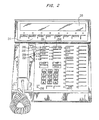
- FIG. 2 illustrates an electronic telephone set;
- FIG. 3 illustrates, in flow chart form, a program for the customer switching system that uses the voice mail system illustrated in FIG. 1 in accordance with the invention;
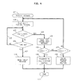
- FIG. 4 illustrates the program, in flow chart form, for the voice mail system system in accordance with the invention;
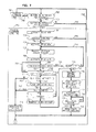
- FIG.5 illustrates, in flow chart form, a program for the customer switching system illustrated in FIG. 1 using a standard telephone set in accordance with the invention;
- FIG. 6 illustrates, in block diagram form, the audio unit of FIG. 1;
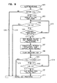
- FIG. 7 illustrates, in flow chart form, a program for controlling the operation of the audio unit of FIG. 1 in accordance with the invention;
- FIG. 8 illustrates an interface of the customer premise unit of FIG. 1;
- FIG. 9 illustrates, in flow chart form, an addition to the program for controlling the operation of the audio unit of FIG. 1 to provide additional operations in accordance with the invention;
- FIG. 10 illustrates, in block diagram form,
communication terminal 133 of FIG. 1; - FIG. 10 illustrates the exterior design of
communication terminal 133 of FIG. 1; and - FIG. 12 illustrates, in flow chart form, a program for controlling the operation of
terminal controller 1003 of FIG. 10 in accordance with the invention. - FIG. 1 illustrates three embodiments in accordance with the invention that allow a called party, while engaged in a first call, to indicate to a second calling party that the called party will respond to the second call within a waiting time interval. The first embodiment is a combination of
systems Customer premise unit 140 is the second embodiment, andcommunication controller 133 is the third embodiment, The function that allows a called party to respond to a second call via a voice announcement device is referred to as the personal answer message feature. - The following is an example of the first embodiment in accordance with the invention. If
telephone 130 is engaged in a first call with electronic telephone set 132 via switchingnetwork 101 and a second call is placed fromtelephone 131 to electronic telephone set 132, the called party activates the personal answer button onset 132. In response to activation of the latter button, switchingprocessor 102interconnects telephone 131 to voicemail system system 110 via an audio line incable 104. In addition, switchingprocessor 102 transmits a digital message to featureprocessor 112 ofvoice mail system 110 viaDCIU 103 andcable 105 regarding (1) the personal answer message to be generated, (2) the telephone number of the second calling party, (3) telephone number of the called party, and (4) the identification of the audio link withincable 104 that transfers the second call to voicemail system 112.Feature processor 112 then utilizes the called party number to access database processor 113 to obtain the name of called party. Utilizing the name of the called party,feature processor 112 actuatesvoice storage processor 111 to transmit via the audio link the personal answer message to the second calling party ontelephone 131. Advantageously, the message is "John Doe is presently engaged in another telephone conversation, but he is aware of your call and will be with you in thirty seconds. If you wish to leave a voice mail message, press " 1" ; if you wish to speak to his secretary, press "0"; or if you wish to speak to John Doe, please wait."Feature processor 112 then transmits a message back to switchingprocessor 102 indicating that the call from telephone set 131 should be camped ontoelectronic telephone set 132. If the called party does not respond within the waiting time interval, switchingprocessor 102 processes the call in the normal manner. The normal manner may include transferring the call to messagecenter service system 120, to voicemail service system 110, or to a secretary so that a message can be taken for the called party. The operation of the systems 100,110, and 120 illustrated in FIG. 1 is explained in greater detail in U. S. Patent 4,790,003. - The following describes the operations that the called party performs on electronic telephone set 132 in the above example. The manner in which control, audio, and data signals are transmitted between electronic telephone set 132 and
customer switching system 100 is described in U.S. Patent 4,734,931. When the called party is speaking to the first calling party ontelephone set 130, this fact is indicated on electronic telephone set 132 (as illustrated in FIG. 2) byindicator lights 205 being illuminated. When the second call fromtelephone set 131 is detected by switchingprocessor 102, the latter processor communicates information to electronic telephone set 132 notifying the called party of the presence of the second call by flashingindicator light 206 and activating the ringer inelectronic telephone set 132. The called party determines who is calling by activatinginspection button 211. The name of the second calling party is then displayed onalphanumeric display 210 using well known techniques as described in U.S. Patent 4,790,004. If the called party wishes to have the personal answer message transmitted to the second calling party, the called party depressespersonal answer button 204. In response to the actuation ofpersonal answer button 204, switchingprocessor 102 transfers the second call to voicemail system 110. The latter system sends the personal answer message to the second calling party and determines whether the second calling party wants to be placed in a standby mode (on hold), to leave a voice mail message, or to be routed through normal call coverage to a secretary. - If the second calling party wants to be placed on hold, the following events take place: after receiving confirmation from
voice mail system 110 that the personal answer message has been transmitted totelephone set 131 and that the second calling party wishes to be placed on hold, switchingprocessor 102 causes indicator light 206 to flash indicating that this call has been placed on hold. As is well known in the art,service processor 102 may provide music to the second calling party via switchingnetwork 101. When the called party completes the first call, the called party pushesbutton 202 to pick up the second call. If the second calling party ontelephone set 131 has chosen to leave a message rather than be put on hold,service processor 102 is informed of this fact by voicemail service system 110.Service processor 102 activates indicator light 200 indicating that a message is waiting. The called party can retrieve the message using well known techniques. - FIG. 3 illustrates, in flow chart form, a programming routine executed by
switch processor 102 to provide the personal answer message feature.Block 301 determines if a call has originated for a telephone set.Decision block 302 determines If the called telephone set is presenlly handling a call (first call). If there is not a first call, then control is transferred viapath 321 to block 313 whereswitch processor 102 processes the call using well known techniques. If the telephone set is presently handling a first call, control is transferred viapath 320 to decision block 303 which determines called party a reaction time interval to respond to the second call by answering the call or by pushing the personal answer button before the call is transferred to normal call processing.Decision block 307 provides this the reaction time interval. Until the reaction time interval has elapsed,decision block 307 continuously transfers control back todecision block 304. After the reaction time interval has expired,decision block 307 transfers control via path 325 to block 313. If the called party answers the second call, then control is passed to block 313 viapath 324. If the called party activates the personal answer button,decision block 305 transfers control via path 326 to block 308. - In
block 308,switch processor 102 transmits to voice mail system 110a message containing a request to generate the personal answer message, the calling party's number, the called party's number, and the identification of the audio link incable 104 that communicates the call to voicestorage processor 111. Also inblock 308,switch processor 102 connects the second calling telephone set to the identified audio link via switchingnetwork 101. Inblock 309,switch processor 102 waits for a message fromvoice mail system 110. When the message is received fromvoice mail system 110,decision block 310 determines if the calling party indicated a decision to be placed on hold. If the calling party has indicated the decision to be placed on hold to voicemail system 110, control is transferred viapath 330 to block 311. If the second calling party has chosen to leave a message, then switchprocessor 102 terminates this call with respect to the personal answer message feature. -
Block 311 places the second call to be placed on hold using the standard call processing features ofswitch processor 102.Block 311 also indicates this fact to the called party as described in the previous paragraph. Control is then transferred to decision blocks 312 and 314 which provide the called party the waiting time interval to answer the second call. If the called party answers the second call during the waiting time Interval,decision block 314 detects this fact and control is transferred to block 313 viapath 328 for normal processing of an answered call. If the second call is not answered during the waiting time interval, control is transferred to block 313 viapath 327 for the call to be processed as an unanswered call. - FIG. 4 illustrates the portion of the program of
feature processor 112 which implements the personal answer message feature. Whenfeature processor 112 receives a message indicating that the personal answer message feature is invoked, control is transferred toentry point 401.Block 402 transmits the personal answer message on the audio link selected byswitch processor 102. After the personal answer message is transmitted, control is passed to decision blocks 403 and 404 so that the calling party has an opportunity to indicate the desired course of action.Decision block 403 detects when a multi-frequency key is depressed on the calling telephone set. If no key is detected,decision block 403 transfers control todecision block 404. The latter block performs a timing function for the reaction time interval during which the multi-frequency testing is done. If the reaction time interval has elapsed indicating that the second calling party wants to be placed on hold, control is transferred viapath 421 to block 410. The latter block sends the message that the second calling party wishes to be put on hold to switchprocessor 102 viapath 105 andDCIU unit 103. If the reaction time interval has not elapsed,decision block 404 transfers control back to decision block 403 viapath 420. - If a multi-frequency digit is detected by
decision block 403, control is transferred viapath 422 to block 405.Block 405 generates a message indicating that the voice mail system is now taking over the call and transmits this message to switchprocessor 102. Decision blocks 406 and 407 then determine which multi-frequency character has been detected. If the digit "0" is detected, control passes to block 408 which causesswitch processor 102 to handle the second call via call coverage (secretarial pick-up) using well-known techniques in the art for coordinating the transfer of the second calling party fromvoice mail system 110 to call coverage. Ifdecision block 407 detects the digit "1" indicating that the second calling party wants to leave a message for the called party onvoice mail system 110, then block 409 causes the normal functions for taking messages of voicemail service system 110 to be executed. - Advantageously, the benefits of the invention can also be applied to simple telephone sets such as telephone set 130 equipped with multi-frequency dialing. If the user of telephone set 130 (the called party) Is engaged in a first call and a second call is placed to
telephone set 130, switchingprocessor 102, which utilizestone generator 153 andswitching network 101, gives a brief ringing tone. This tone is heard only by the called party. This brief ringing tone notifies to the called party that a second call is waiting. If the called party wishes to have the personal answer message sent to the second second calling party, the called party actuates a flash hook operation.Switching processor 102 responds to the flash hook by connecting the second calling party to voicemail system 110 as previously described. Ifvoice mail system 110 determines that the second calling party wishes to be placed on hold for the waiting time interval, switchingprocessor 102 marks the second call as being camped ontotelephone set 130.Switch processor 102 transmits, viatone generator 153 andswitching network 101, a "call on hold" tone totelephone set 130. This tone is heard only bytelephone set 130. - When the called party terminates the first call, the second call is immediately connected to
telephone set 130. If the second call is terminated or if the waiting time interval lapses before the first call is terminated, the called party receives the "call on hold" tone a second time to signify that the second call is no longer present. - FIG. 5 illustrates, in flow chart form, the program routine executed by
switch processor 102 that provides the personal answer message feature for analog telephone sets equipped with multi-frequency dialing.Block 501 determines that a call has originated for the telephone set,Decision block 502 determines if the called telephone set is busy with a first call. If the telephone is not busy, control is transferred viapath 521 to block 513 whereswitch processor 102 processes the call using well known techniques. If the telephone set is busy, control is transferred viapath 520 to decision block 503 which determines whether or not the personal answer message feature is administered for this particular telephone set, If the feature is administered for the telephone set, control is transferred viapath 522 todecision block 504. If the feature is not administered for the telephone set, control is passed viapath 521 to block 513. -
Blocks Decision block 507 provides the reaction time interval and continuously returns control to decision block 504 until the reaction time interval is finished; whereupondecision block 507 transfers control viapath 525 to block 513. If the called party answers the second call, then control is passed to block 513 viapath 524. If the called party executes a flash hook operation,decision block 505 transfers control viapath 526 to block 508. - In
block 508,switch processor 102 transmits to voice mail system 110 a message containing a request to generate the personal answer message, the calling party's number, the called party's number, and the identification of the audio link incable 104 that communicates the second call to voicestorage processor 111. Also inblock 508,switch processor 102 connects the second calling telephone set to the identified audio link via switchingnetwork 101. Inblock 509, switchingprocessor 102 waits for a message fromvoice mail system 110. When the message is received fromvoice mail system 110,decision block 510 determines whether or not the calling party indicated a decision to be placed on hold. If the calling party has indicated tovoice mail system 110 the decision to be placed on hold, control is transferred via path 530 to block 511. If the second calling party has chosen to leave a message, then switchprocessor 102 terminates this call with respect to the personal answer message feature. -
Block 511 sends a tone indicating that the second call has been placed on hold to the called party. Control is then transferred to block 515 which camps the second call onto the called telephone set using the standard call processing features ofswitch processor 102. Next, control is transferred to decision blocks 512 and 514, which give the called party the waiting time interval to terminate the first call. In addition,decision block 512 detects if the second call has been terminated. If the called party terminates the first call during the waiting time interval,decision block 514 detects this fact and control is transferred to block 516 viapath 528. The latter block connects the second call to the called telephone set. If the first call has not been terminated, control is passed to decision block 517 which checks if the second call has been terminated. If the second call has been terminated, the "call on hold" tone is transmitted to the called telephone set byblock 516; then, control is passed to block 513. If the second call has not been terminated, control is returned to decision block 512 viapath 529. If the first call is not terminated in the waiting time interval, control is passed to block 519 viapath 527; and block 519 transmits the "call on hold" tone to the called telephone set.Block 519 then transfers control to block 513 which processes the second call as an unanswered call. -
Customer premise unit 140 of FIG. 1 illustrates another embodiment in accordance with the invention for providing a personal answer message to a second calling party.Customer premise unit 140 is assumed to be located either in a private residence or in a small business location.Unit 140 is interconnected viatelephone lines central exchange office 135. An example of the operation ofcustomer premise unit 140 follows. If a first call is in progress ontelephone set 149 and a second call is directed totelephone 142 viatelephone line 146 bycentral exchange office 135, the called party activatesbutton 144 oninterface 143 to have the personal answer message transmitted to the second calling party. The called party is notified of the second call bytelephone set 142 ringing. In response to the actuation ofbutton 144,audio unit 141 connects itself totelephone line 146.Audio unit 141 then verifies that there is ringing ontelephone line 146. After the ringing verification,audio unit 141 transmits the following personal answer message ontelephone line 146. "John Doe is presently engaged in another telephone conversation, but he is aware of your call and will be with you in thirty seconds or less. If you wish to wait, please remain on the line. If you wish to leave an audio message, press '1' on your telephone." Advantageously,audio unit 141 also detects multi-frequency tones so that the second calling party can indicate whether she/he wants to be placed in a standby mode (on hold) or leave an audio message. If the second calling party indicates that he/she wishes to be placed on hold, thenaudio unit 141 continues the connection totelephone line 146 andflashes indicator 145 so that the called party knows that the second calling party is on hold, - FIG. 6 illustrates
audio unit 141 in greater detail.Microprocessor 601 controls the overall operation ofaudio unit 141.Voice synthesizer 607 generates audio messages under control ofmicroprocessor 601.Voice recorder 606 records the message from the second calling party.Multi-frequency detector 609 detects the depression of a multi-frequency key by a second calling party and transmits the identity of the key tomicroprocessor 601.Detector 608 detects ringing, an active call, and telephone set 142 or 149 going off hook.Relays 602 through 605 as well as 619interconnect telephone lines cables 620 through 623.Microprocessor 601 may advantageously be a R65F11 manufactured by Rockwell Incorporated with built-in peripheral units for controllingpaths 610 through 618 andcables Voice synthesizer 607 utilizes the SP0256-AL2 manufactured by General Instruments, Inc..Voice recorder 607 is a voice actuated tape recorder controlled bymicroprocessor 601. - Consider how the circuit of FIG. 6 implements the previous example. When the called party presses
button 144 in response to ringing ontelephone 142,microprocessor 601 responds to a signal transmitted viacable 151 frombutton 144 to activaterelay 603. The latter relay connectstelephone line 146 topath 620.Microprocessor 601 then interrogatesdetector 608 to verify that there is ringing ontelephone line 146 fromcentral exchange office 135. After the ringing verification,microprocessor 601 activates relay 604 to interconnectvoice synthesizer 607 topath 620.Microprocessor 601 next controls the operation ofvoice synthesizer 607 by the transmission of information onpath 615. Aftermicroprocessor 606 has transmitted the personal answer message viavoice synthesizer 607,microprocessor 601 activates relay 619 vialine 618.Microprocessor 601 monitorsmulti-frequency detector 609 for a reaction time interval viapath 617 to determine ifmulti-frequency detector 609 has detected the depression of a multi-frequency key. - If the second calling party does not depress a multi-frequency button indicating he/she did not want to leave a message,
microprocessor 601flashes indicator 145 oninterface 143 viacable 151. During the flashing ofindicator 145,microprocessor 601 withdetector 608 detects if a call remains ontelephone line 146.Microprocessor 601 then provides for the waiting time interval (30 seconds in the present example). If the waiting time interval elapses,microprocessor 601 usesvoice synthesizer 607 to give the second calling party the following "sorry" message. "Sorry, John Doe is unable to answer your call, but you may now leave a message for him." In addition,microprocessor 601 determines if the called party has answered the second call by monitoringtelephone 142 withdetector 608. Ifmicroprocessor 601 determines thatline 146 is no longer active or that the called party has answered the second call,microprocessor 601stops flashing indicator 145. - If the second calling party wishes to leave a voice message,
microprocessor 601 viavoice synthesizer 607 plays a "record" message indicating that the second calling party should start speaking.Microprocessor 601 then activatesvoice recorder 606 to receive the second calling party's message. Advantageously, the record message is "At the tone, please leave your message."Voice recorder 606 utilizes well known techniques to record only when an individual is speaking.Microprocessor 601 detects the end of the second call viadetector 608 and deactivatesvoice recorder 606 as well asrelays 602 through 605. - FIG. 7 illustrates, in flowchart form, the program executed by
microprocessor 601. Advantageously, this program is implemented onmicroprocessor 601 in the FORTH programming language.Block 700 handles the processing oftelephone line 146.Block 701 is similar to block 700 and handles the processing oftelephone line 147. In the idle state,microprocessor 601 continuously executes decision blocks 702 and 703 which checks for activation of the buttons oninterfaces interface 148 is activated,decision block 702 transfers control viapath 730 to block 701. Otherwise,decision block 702 transfers control viapath 731 todecision block 703. If the button oninterface 143 has been activated,decision block 703 transfers control to block 704 viapath 733. If the button oninterface 143 has not been activated,decision block 703 transfers control back to decision block 702 viapath 732. - Once
button 144 is activated oninterface 143 and control is transferred to block 704, block 704 activates relay 603 which connectstelephone line 146 topath 620. Next,decision block 705 detects if ringing is present ontelephone line 146. If ringing is detected, control is transferred viapath 735 to block 706, which activatesrelay 604.Relay 604 connectsvoice synthesizer 607 topath 620 viapath 622.Block 707 then transmits the personal answer message which gives instructions to the second calling party viavoice synthesizer 607.Block 708 activatesrelay 619 so thatmulti-frequency detector 709 is interconnected topath 620 viapath 623 andrelay 619. If ringing is not present, control is transferred bydecision block 705 via path 734 back to decision block 702, since thebutton 144 had been erroneously activated. - Decision blocks 709 and 710 give the second calling party a reaction time interval to decide whether to leave a voice message or to remain on the telephone line until the called party answers.
Decision block 709 interrogatesmulti-frequency detector 609 to determine if a multi-frequency digit has been detected. If a multi-frequency digit has been detected, control is transferred viapath 736 todecision block 715.Decision block 715 determines if the received digit is a "1." If the received digit is not a "1," control is transferred viapath 744 to block 707 to give the second calling party an opportunity to try again. If a digit has not been detected, control is transferred viapath 737 todecision block 710. - If the received multi-frequency digit is a "1," control is transferred via
path 745 to block 716. Inblock 716,microprocessor 601 transmits the appropriate information to voicesynthesizer 607 so that the second calling party is instructed to leave a voice message.Block 717 then deactivatesrelays relay 605. The activation ofrelay 605 interconnectsvoice recorder 606 viapath 621,relay 605,path 620, and relay 603 totelephone line 146.Block 718 then activatesrecorder 606.Recorder 606 is voice activated and records only when the second calling party is leaving a message.Decision block 719 then determines whether or not the call is active. If the call is active,path 746 repeats the test If the call has been dropped or is no longer active,decision block 719 transfers control viapath 747 to block 720.Block 720 deactivatesrelays path 748. - If control is transferred by
decision block 709 to decision block 710 viapath 737 because no multi-frequency digit is detected,decision block 710 determines if the reaction time interval has elapsed. If the time has not elapsed, control is transferred viapath 738 back todecision block 709. If the reaction time interval has elapsed, then control is transferred viapath 739 todecision block 711. Since the second calling party did not actuate a multi-frequency button, it is assumed that the second calling party decided to be placed "on hold" until the called party finishes the conversation ontelephone line 147. - Blocks 711,712,713, and 721 are concerned with flashing
indicator 145 and with determining (1) if the second calling party terminates the call, (2) if the called party answers the call, and (3) if the waiting time interval has elapsed. When the second call has been terminated or answered,audio unit 141 returns to the idle state and control returns to decision block 702 viapath 748. Once the waiting time interval has elapsed, control is transferred to block 722 which transmits to the second calling party the sorry message. Next, block 716 gives the second calling party the opportunity to leave a message. - Decision blocks 711 and 713 utilize
detector 608 to determine if the call has been terminated or answered. If the call is still active,decision block 711 transfers control viapath 741 to block 712. If the call is not active, control is transferred viapath 740 to block 714.Block 712flashes indicator 145 once each time the block is executed and transfers control todecision block 713. If the second call has been answered,decision block 713 transfers control to decision block 714 viapath 742. If the call has not been answered, control is transferred to decision block 711 viapath 743.Decision block 714 deactivatesrelays path 748. - If
interface unit 800 of FIG. 8 replacesinterfaces audio unit 141. First,microprocessor 601 continuously displays the amount of time that has elapsed since the second calling party was put on hold. Second, if the called party actuatespersonal answer button 801 while the second calling party is on hold,microprocessor 601 sets the timed period back to the waiting time interval and transmits a continuation message viavoice synthesizer 607 to the second calling party. The continuation message is as follows: "John Doe regrets that he hasn't answered your call but has indicated his desire that you hold for another thirty seconds." - FIG. 9 illustrates, in flowchart form, the additions to the program of FIG. 7 that implement the above features on
interface unit 800.Blocks 901 through 904 replaceblock 712 of FIG. 7. Block 901 displays the remaining time ondigital display 802 andflashes indicator 803.Decision block 902 detects the actuation ofpersonal answer button 801. Whenbutton 801 is actuated, control is transferred to block 903 which transmits the continuation message to the second calling party. Then, block 904 resets the time interval back to the waiting time interval. Ifbutton 801 has not been actuated, control is transferred to block 713 of FIG. 7 viapath 750. - FIG. 10 and FIG. 11 illustrate a third embodiment in accordance with the invention. FIG. 10 illustrates the circuit of
communication terminal 133, and FIG. 11 illustrates the exterior design ofcommunication terminal 133.Communication terminal 133 is interconnected tocentral exchange office 135 via basic rate interface (BRI) link 158. BRI link 158 has two B channels for the communication of voice/data information and one D channel for the communication of signaling information.ISDN interface 1001 interfaces withBRI link 158 and communicates the first B channel ontopath 1010 and the second B channel ontopath 1011.ISDN interface 1001 communicates the D channel onpath 1012.Terminal controller 1003 controlsISDN interface 1001 viapath 1013.ISDN interface 1001 may be advantageously constructed using two AM79C30 integrated circuits manufactured by Advanced Micro Devices,Inc Terminal controller 1003 is a microprocessor with random access memory, read only memory, and peripheral controllers. - The information on
paths switch matrix 1002 tohandset 1009 via path 1014, tovoice recorder 1006 via path 1015, and tovoice synthesizer 1007 via path 1016.Terminal controller 1003 controls the switching functions ofswitch matrix 1002 viapath 1021. Further,terminal controller 1003 controls the operations ofvoice recorder 1006 andvoice synthesizer 1007 viapath 1017. -
Terminal 133 also comprises an alphanumeric display, buttons and indicator lights as illustrated in FIG. 11.Terminal controller 1003 controls the alphanumeric display withdisplay module 1005 by information transmitted via path 1019, interrogates the buttons withbutton module 1008 viapath 1018, and illuminates the indicator lights withindicator light module 1004 viapath 1020. - The following is an example of the third embodiment in accordance with the invention. If
telephone 130 is engaged in a first call with communication terminal 133 (via switchingnetwork 101,central exchange office 135, and the first B channel) and a second call is placed fromtelephone 131 tocommunication terminal 133, an alerting message is transmitted fromcentral exchange office 135 tocommunication terminal 133 via the D channel.Terminal controller 1003 is responsive to this alerting message to exchange messages withcentral exchange office 135 negotiating that the second call should be placed on the idle second B channel ofBRI link 158. To notify the called party,terminal controller 1003 then utilizes the calling party identification received fromcentral office 135 and displays this identification ondisplay 1110 via display module 1019. Ifcentral exchange office 135 does not provide the calling party identification,terminal controller 1003 displays the message "second call" ondisplay 1110. The called party activatespersonal answer button 1104 oncommunication terminal 133. In response to activation of button 1109,terminal controller 1003 connects the second B channel onpath 1011 throughswitch matrix 1002 tovoice synthesizer 1007.Terminal controller 1003 then activatesvoice synthesizer 1007 which transmits the personal answer message to the second calling party. Advantageously, the voice message is "John Doe is presently engaged in another telephone conversation, but he is aware of your call and will be with you in 30 seconds or less."Terminal controller 1003 then times the 30 second interval (waiting time interval) while flashing indicator light 1106 to indicate that the second call has been placed in a standby mode (on hold). When the called party completes the first call, the called party actuatesbutton 1102 to pick up the call.Terminal controller 1003 detects this actuation viabutton module 1008 andswitches path 1011 tohandset 1009 viaswitch matrix 1002 and path 1014. If the called party does not complete the first call within the waiting time interval,terminal controller 1003switches path 1011 tovoice recorder 1006 viaswitch matrix 1002.Terminal controller 1003 then utilizesvoice synthesizer 1007 to inform the second calling party that he/she may leave a message. When a message has been left,terminal controller 1003 activates indicator light 1100 to signify that a message is waiting. - The following describes the operations that the called party performs on
communication terminal 133 in the above example. When the called party is speaking to the first calling party, this state is indicated on communication terminal 133 (as illustrated in FIG. 11) byindicator lights 1105 being illuminated. When the second call fromtelephone set 131 is detected byterminal controller 1003, the latter processor notifies the called party of the presence of the second call by flashingindicator light 1106 and activating a ringer vialight module 1004. The called party determines who is calling by activating inspection button 1111, and the name of the second calling party is displayed onalphanumeric display 1110. If the called party wishes to have the personal answer message transmitted to the second calling party, the called party actuatespersonal answer button 1104. In response to the actuation ofpersonal answer button 1104,terminal controller 1003 connects the second call to voicesynthesizer 1007 and controls the latter unit to transmit the personal answer message to the second calling party. When the called party completes the first call, the called party pushesbutton 1102 to pick up the second call. - FIG. 12 illustrates, in flow chart form, a programming routine executed by
terminal controller 1003 to provide the personal answer message feature oncommunication terminal 133.Block 1201 is entered when the alerting message is received fromcentral exchange office 135.Decision block 1202 determines ifcommunication terminal 133 is presently handling a call (the first call). If there is not a first call, then control is transferred viapath 1220 to block 1211 whereterminal controller 1003 processes the call using well known techniques. Ifcommunication terminal 133 is presently handling a first call, control is transferred viapath 1212 to block 1203 which displays the calling party's name. Control is then transferred todecision block 1204. The latter block gives the called party a reaction time interval to respond to the second call by pushing the personal answer button before the call is transferred to normalcall processing block 1211. Until the reaction time interval has elapsed,decision block 1204 continuously transfers control todecision block 1205. After the reaction time interval has expired,decision block 1204 transfers control viapath 1219 to normalcall processing block 1211. In response to this transfer,block 1211 sends a rejection message tocentral exchange office 135. - If the called party activates the personal answer button,
decision block 1205 transfers control viapath 1214 to block 1206. Inblock 1206,terminal controller 1003 transmits to central exchange office 135 a message designating that the second call should be communicated on the idle B channel. Control is transferred to block 1207 which connectsvoice synthesizer 1007 to the second call and transmits the personal answer message to the second calling party. Next, block 1208 causesindicator 1102 to be flashed. Advantageously, the personal answer message may also be in the form of a data message transmitted via the D channel if the second call is placed from another communication terminal. The other communication terminal then displays the personal answer message on the alphanumeric display. - From
block 1208, control is transferred todecision blocks decision block 1209 detects this fact and control is transferred to block 1211 viapath 1215 for normal processing of an answered call. If the second call is not answered during the waiting time interval, control is transferred to block 1221. The latter block usesvoice recorder 1006 andvoice synthesizer 1007 to record a message from the second calling party. Control is then transferred to block 1211 which terminates the second call.
Claims (10)
- A method of communicating between a calling party and a called party already engaged in a first call and said called party utilizing a communication terminal, and said method comprising the steps of:
notifying said called party via said communication terminal of the origination of a second telephone call from said calling party;
activating an automatic response to said calling party by said called party via said communication terminal in response to the notification;
said step of activating said automatic response comprises the steps of automatically indicating to said calling party that said called party is aware of said second call; and
automatically placing said second call in a standby mode for said called party in response to the activation. - The method of claim 1 wherein said indicating step comprises the step of transmitting a voice message to said calling party.
- The method of claim 2 wherein said voice message specifies that said called party will respond to said calling party within a waiting time interval; and
said placing step comprises the steps of timing for said waiting time interval; and
connecting said second call to a message taking service upon said waiting time interval elapsing without said called party answering said second call thereby allowing said calling party to leave a message. - The method of claim 3 further comprising activating, by said called party, another automatic response to said calling party;
said transmitting step further retransmitting another voice message to said calling party in response to the actuation of said other automatic response; and
said timing step comprises the step of initializing said timing step to time for the entirety of said waiting time interval in response to the actuation of said other automatic response. - The method of claim 3 wherein said timing step further comprises the step of displaying the time remaining of said waiting timing interval to said called party.
- An apparatus for communicating between a calling party and a called party already engaged in a first call and said called party utilizing a communication terminal, and said apparatus comprising:
means (153,142,145) for notifying said called party via said communication terminal of the origination of a second telephone call from said calling party;
means (141,143,148) for activating an automatic response to said calling party by said called party via said communication terminal in response to the notification;
said means (607) for activating said automatic response comprises means for automatically indicating to said calling party that said called party is aware of said second call; and
means (602, 603, 608) for automatically placing said second call in a standby mode for said called party in response to the activation. - The apparatus of claim 6 wherein said indicating means comprises the means for transmitting a voice message to said calling party.
- The apparatus of claim 7 wherein said voice message specifies that said called party will respond to said calling party within a waiting time interval; and
said placing means comprises means for timing for said waiting time interval; and
means for connecting said second call to a message taking service upon said waiting time interval elapsing without said called party answering said second call thereby allowing said calling party to leave a message. - The apparatus of claim 8 further comprises activating, by said called party, another automatic response to said calling party; said transmitting means further retransmitting another voice message to said calling party in response to the actuation of said other automatic response; and
said timing means comprises means for initializing said timing means to time for the entirety of said waiting time interval in response to the actuation of said other automatic response. - The apparatus of claim 8 wherein said timing means further comprises means for displaying the time remaining of said waiting timing interval to said called party.
Applications Claiming Priority (2)
| Application Number | Priority Date | Filing Date | Title |
|---|---|---|---|
| US454555 | 1989-12-21 | ||
| US07/454,555 US5034975A (en) | 1989-12-21 | 1989-12-21 | Voice announcement device for improving functionality of multi-line telephones |
Publications (3)
| Publication Number | Publication Date |
|---|---|
| EP0434239A2 true EP0434239A2 (en) | 1991-06-26 |
| EP0434239A3 EP0434239A3 (en) | 1993-02-17 |
| EP0434239B1 EP0434239B1 (en) | 1996-09-25 |
Family
ID=23805092
Family Applications (1)
| Application Number | Title | Priority Date | Filing Date |
|---|---|---|---|
| EP90312884A Expired - Lifetime EP0434239B1 (en) | 1989-12-21 | 1990-11-27 | Voice announcement device for improving functionality of multi-line telephones |
Country Status (4)
| Country | Link |
|---|---|
| US (1) | US5034975A (en) |
| EP (1) | EP0434239B1 (en) |
| CA (1) | CA2031056C (en) |
| DE (1) | DE69028686T2 (en) |
Cited By (9)
| Publication number | Priority date | Publication date | Assignee | Title |
|---|---|---|---|---|
| WO1996017488A1 (en) * | 1994-12-01 | 1996-06-06 | Telefonaktiebolaget Lm Ericsson | Subscriber service in a telecommunication network |
| GB2301981A (en) * | 1995-06-07 | 1996-12-18 | Mitel Corp | Telephone system having soft call park feature with comfort notification to caller |
| EP0776565A1 (en) * | 1994-08-11 | 1997-06-04 | Quantum Systems, Inc. | Improved communications marketing system |
| EP0902579A2 (en) * | 1997-09-13 | 1999-03-17 | Deutsche Telekom AG | Method for establishing a hold state of a connection between two terminals |
| WO1999027699A2 (en) * | 1997-11-17 | 1999-06-03 | Nokia Networks Oy | Method of transmitting an acknowledgement to an a-subscriber |
| WO1999030473A1 (en) * | 1997-12-05 | 1999-06-17 | Telefonaktiebolaget Lm Ericsson | A method and system for automatic answering and recording of messages in a telephone system |
| GB2311189B (en) * | 1996-03-15 | 2000-06-21 | Casio Phonemate Inc | Voice mail telephone answering device |
| WO2002045395A1 (en) * | 2000-11-29 | 2002-06-06 | Nokia Corporation | Wait-time service in a telecommunications network |
| WO2003021926A2 (en) * | 2001-09-05 | 2003-03-13 | Koninklijke Philips Electronics N.V. | Telephone on-hold response system |
Families Citing this family (35)
| Publication number | Priority date | Publication date | Assignee | Title |
|---|---|---|---|---|
| JPH0652914B2 (en) * | 1990-09-21 | 1994-07-06 | 橋本コーポレイション株式会社 | Caller telephone number display |
| US5479493A (en) * | 1992-05-21 | 1995-12-26 | At&T Corp. | Calling line identification adjunct for use with a communication system |
| US5400393A (en) * | 1992-06-05 | 1995-03-21 | Phonemate, Inc. | Voice mail digital telephone answering device |
| US5511115A (en) * | 1993-03-08 | 1996-04-23 | At&T Corp. | Apparatus and method for programming a repertory dial button of a station terminal |
| US5396371A (en) * | 1993-12-21 | 1995-03-07 | Dictaphone Corporation | Endless loop voice data storage and retrievable apparatus and method thereof |
| US5668861A (en) * | 1993-12-23 | 1997-09-16 | Gte Laboratories Incorporated | Telecommunications system with notification hold |
| US5812639A (en) * | 1994-12-05 | 1998-09-22 | Bell Atlantic Network Services, Inc. | Message communication via common signaling channel |
| US5631948A (en) * | 1994-12-05 | 1997-05-20 | Bell Atlantic Network Services, Inc. | Voice mail communication with call blocking |
| US6215858B1 (en) | 1994-12-05 | 2001-04-10 | Bell Atlantic Network Services, Inc. | Analog terminal internet access |
| US6285745B1 (en) | 1994-12-05 | 2001-09-04 | Bell Atlantic Network Services, Inc. | Analog terminal internet access |
| CA2159383C (en) * | 1994-12-22 | 1999-01-12 | Bruce Merrill Bales | Automatic call back under control of a telephone terminal |
| US5572587A (en) * | 1995-03-08 | 1996-11-05 | Advanced Micro Devices | Telephone system and method for easing wait time in queue |
| GB9603582D0 (en) | 1996-02-20 | 1996-04-17 | Hewlett Packard Co | Method of accessing service resource items that are for use in a telecommunications system |
| KR100206178B1 (en) * | 1996-03-28 | 1999-07-01 | 윤종용 | Key phone monitoring method |
| US6438218B1 (en) | 1996-04-18 | 2002-08-20 | Robert D. Farris | Internet telephone service |
| US6154445A (en) * | 1996-04-18 | 2000-11-28 | Bell Atlantic Network Services, Inc. | Telephony communication via varied redundant networks |
| US6069890A (en) * | 1996-06-26 | 2000-05-30 | Bell Atlantic Network Services, Inc. | Internet telephone service |
| US6125113A (en) * | 1996-04-18 | 2000-09-26 | Bell Atlantic Network Services, Inc. | Internet telephone service |
| KR100222781B1 (en) * | 1996-05-31 | 1999-10-01 | 윤종용 | Telephone number searching method |
| US5850429A (en) * | 1996-12-11 | 1998-12-15 | Lucent Technologies Inc. | Method and system for remotely controlling an interactive voice response system |
| US6078582A (en) | 1996-12-18 | 2000-06-20 | Bell Atlantic Network Services, Inc. | Internet long distance telephone service |
| US6137869A (en) | 1997-09-16 | 2000-10-24 | Bell Atlantic Network Services, Inc. | Network session management |
| US6870827B1 (en) | 1997-03-19 | 2005-03-22 | Verizon Services Corp. | Voice call alternative routing through PSTN and internet networks |
| US6292479B1 (en) | 1997-03-19 | 2001-09-18 | Bell Atlantic Network Services, Inc. | Transport of caller identification information through diverse communication networks |
| US6041114A (en) | 1997-03-27 | 2000-03-21 | Active Voice Corporation | Telecommute server |
| US6154644A (en) * | 1998-09-08 | 2000-11-28 | Telefonaktiebolaget L M Ericsson | System and method of implementing an interactive callback feature in a radio telecommunications network |
| DE19928256B4 (en) * | 1999-06-21 | 2012-12-13 | Siemens Ag | Method and arrangement for establishing a communication connection |
| US6381322B1 (en) * | 1999-10-04 | 2002-04-30 | Avaya Technology Corp. | System for processing incoming calls based on call priority for telephone stations having multiple lines |
| DE10206400A1 (en) * | 2002-02-15 | 2003-09-04 | Siemens Ag | Call forwarding involves holding call and connection between first and second ports for voice connection active when call received at first port while setting up link to intended port |
| AU2002952987A0 (en) * | 2002-11-28 | 2002-12-12 | Jackson Technologies Pty Ltd | Reply system |
| US20040151286A1 (en) * | 2003-01-31 | 2004-08-05 | Shary Nassimi | Self-contained single telephone line voice and internet device with DTMF generation capability |
| US7143769B2 (en) * | 2003-08-11 | 2006-12-05 | Richard Stoltz | Controlling pulse energy of an optical amplifier by controlling pump diode current |
| US8285338B2 (en) * | 2004-03-27 | 2012-10-09 | Avaya Inc | Method and apparatus for incoming call pause notification |
| US8238538B2 (en) | 2009-05-28 | 2012-08-07 | Comcast Cable Communications, Llc | Stateful home phone service |
| US20140038666A1 (en) * | 2012-08-03 | 2014-02-06 | Qualcomm Incorporated | Receiving multiple voice calls in a multi-sim device |
Citations (5)
| Publication number | Priority date | Publication date | Assignee | Title |
|---|---|---|---|---|
| US4661975A (en) * | 1985-03-13 | 1987-04-28 | Bell Communications Research, Inc. | Enhanced call-waiting service |
| JPS62286354A (en) * | 1986-06-04 | 1987-12-12 | Nec Corp | Response system for extension telephone set |
| JPS63253750A (en) * | 1987-04-09 | 1988-10-20 | Nec Corp | Telephone set |
| JPH01190061A (en) * | 1988-01-25 | 1989-07-31 | Canon Inc | Telephone system |
| JPH02142263A (en) * | 1988-11-22 | 1990-05-31 | Nec Corp | Automatic response holding system |
Family Cites Families (4)
| Publication number | Priority date | Publication date | Assignee | Title |
|---|---|---|---|---|
| EP0304652B1 (en) * | 1987-08-25 | 1993-12-01 | Siemens Aktiengesellschaft | Method for a programme-controlled telephone exchange by which service features concerning the realisation of a speech connection are introduced from a subscriber terminal |
| US4947421A (en) * | 1987-12-23 | 1990-08-07 | At&T Bell Laboratories | Call waiting arrangement providing options to both a subsequent calling party and to the called party |
| KR910003923B1 (en) * | 1988-06-30 | 1991-06-15 | 삼성전자 주식회사 | Method transmitting automatic arrangement and out-in ring to a person who in on the line |
| US4899358A (en) * | 1988-08-08 | 1990-02-06 | American Telephone And Telegraph Company At&T Bell Laboratories | Call announcement arrangement |
-
1989
- 1989-12-21 US US07/454,555 patent/US5034975A/en not_active Expired - Lifetime
-
1990
- 1990-11-27 DE DE69028686T patent/DE69028686T2/en not_active Expired - Fee Related
- 1990-11-27 EP EP90312884A patent/EP0434239B1/en not_active Expired - Lifetime
- 1990-11-28 CA CA002031056A patent/CA2031056C/en not_active Expired - Lifetime
Patent Citations (5)
| Publication number | Priority date | Publication date | Assignee | Title |
|---|---|---|---|---|
| US4661975A (en) * | 1985-03-13 | 1987-04-28 | Bell Communications Research, Inc. | Enhanced call-waiting service |
| JPS62286354A (en) * | 1986-06-04 | 1987-12-12 | Nec Corp | Response system for extension telephone set |
| JPS63253750A (en) * | 1987-04-09 | 1988-10-20 | Nec Corp | Telephone set |
| JPH01190061A (en) * | 1988-01-25 | 1989-07-31 | Canon Inc | Telephone system |
| JPH02142263A (en) * | 1988-11-22 | 1990-05-31 | Nec Corp | Automatic response holding system |
Non-Patent Citations (6)
| Title |
|---|
| JOURNAL ON SELECTED AREAS IN COMMUNICATIONS vol. SAC-4, no. 8, November 1986, NEW YORK pages 1188 - 192 NGUYEN Q. DUC 'ISDN TERMINALS AND INTEGRATED SERVICES DELIVERY' * |
| PATENT ABSTRACTS OF JAPAN vol. 12, no. 184 (E-614)28 May 1988 & JP-A-62 286 354 ( NEC CORP. ) * |
| PATENT ABSTRACTS OF JAPAN vol. 13, no. 483 (E-839)2 November 1989 & JP-A-1 190 061 ( CANON INC. ) * |
| PATENT ABSTRACTS OF JAPAN vol. 13, no. 68 (E-716)16 February 1989 & JP-A-63 253 750 ( NEC CORP. ) * |
| PATENT ABSTRACTS OF JAPAN vol. 14, no. 387 (E-967)21 August 1990 & JP-A-2 142 263 ( NEC CORP. ) * |
| PROCEEDINGS OF THE NATIONAL COMMUNICATIONS FORUM vol. 40, no. 1, 29 September 1986, ROSEMONT , ILLINOIS (US) pages 596 - 604 LEVESQUE ET AL 'NETWORK TERMINALS TRENDS IN MULTIMEDIA WORKSTATIONS' * |
Cited By (21)
| Publication number | Priority date | Publication date | Assignee | Title |
|---|---|---|---|---|
| EP0776565A1 (en) * | 1994-08-11 | 1997-06-04 | Quantum Systems, Inc. | Improved communications marketing system |
| EP0776565A4 (en) * | 1994-08-11 | 1999-11-17 | Quantum Systems Inc | Improved communications marketing system |
| US6047184A (en) * | 1994-12-01 | 2000-04-04 | Telefonaktiebolaget Lm Ericsson | Subscriber service in a telecommunication network |
| AU697972B2 (en) * | 1994-12-01 | 1998-10-22 | Telefonaktiebolaget Lm Ericsson (Publ) | Subscriber service in a telecommunication network |
| WO1996017488A1 (en) * | 1994-12-01 | 1996-06-06 | Telefonaktiebolaget Lm Ericsson | Subscriber service in a telecommunication network |
| CN1085029C (en) * | 1994-12-01 | 2002-05-15 | 艾利森电话股份有限公司 | Subscriber service in a telecommunication network |
| GB2301981A (en) * | 1995-06-07 | 1996-12-18 | Mitel Corp | Telephone system having soft call park feature with comfort notification to caller |
| US5754627A (en) * | 1995-06-07 | 1998-05-19 | Mitel Corporation | Method and apparatus for managing calls using a soft call park |
| DE19622969B4 (en) * | 1995-06-07 | 2006-05-18 | Mitel Knowledge Corp., Kanata | Telephone server |
| GB2301981B (en) * | 1995-06-07 | 2000-01-26 | Mitel Corp | User initiated soft call park with recorded voice comfort notification |
| GB2311189B (en) * | 1996-03-15 | 2000-06-21 | Casio Phonemate Inc | Voice mail telephone answering device |
| EP0902579A2 (en) * | 1997-09-13 | 1999-03-17 | Deutsche Telekom AG | Method for establishing a hold state of a connection between two terminals |
| EP0902579A3 (en) * | 1997-09-13 | 2000-02-02 | Deutsche Telekom AG | Method for establishing a hold state of a connection between two terminals |
| WO1999027699A3 (en) * | 1997-11-17 | 1999-07-29 | Nokia Telecommunications Oy | Method of transmitting an acknowledgement to an a-subscriber |
| US6430269B1 (en) | 1997-11-17 | 2002-08-06 | Nokia Networks Oy | Method of transmitting an acknowledgement to an A-subscriber |
| WO1999027699A2 (en) * | 1997-11-17 | 1999-06-03 | Nokia Networks Oy | Method of transmitting an acknowledgement to an a-subscriber |
| WO1999030473A1 (en) * | 1997-12-05 | 1999-06-17 | Telefonaktiebolaget Lm Ericsson | A method and system for automatic answering and recording of messages in a telephone system |
| WO2002045395A1 (en) * | 2000-11-29 | 2002-06-06 | Nokia Corporation | Wait-time service in a telecommunications network |
| US7260202B2 (en) | 2000-11-29 | 2007-08-21 | Nokia Corporation | Wait-time service in a telecommunications network |
| WO2003021926A2 (en) * | 2001-09-05 | 2003-03-13 | Koninklijke Philips Electronics N.V. | Telephone on-hold response system |
| WO2003021926A3 (en) * | 2001-09-05 | 2004-05-27 | Koninkl Philips Electronics Nv | Telephone on-hold response system |
Also Published As
| Publication number | Publication date |
|---|---|
| EP0434239A3 (en) | 1993-02-17 |
| DE69028686D1 (en) | 1996-10-31 |
| US5034975A (en) | 1991-07-23 |
| DE69028686T2 (en) | 1997-03-06 |
| CA2031056C (en) | 1995-01-03 |
| EP0434239B1 (en) | 1996-09-25 |
Similar Documents
| Publication | Publication Date | Title |
|---|---|---|
| EP0434239B1 (en) | Voice announcement device for improving functionality of multi-line telephones | |
| US5502761A (en) | Apparatus and method for relaying calling information to a pager or alternate telephone | |
| US4672660A (en) | Method and system for identifying telephone callers | |
| US5151929A (en) | Computer-controlled radio-paging and telephone communication using recorded voice messages | |
| JP3194571B2 (en) | How to connect a telephone system caller to a called party | |
| US6118861A (en) | Calling party invoked held call monitoring | |
| EP1038384B1 (en) | System and method of responding to an incoming call while conferencing | |
| US20050147227A1 (en) | Method and system for alerting call participant of a change in a call hold status | |
| JPH01213094A (en) | Key-telephone system | |
| EP0216515A2 (en) | Method of and apparatus for connecting remote users of a telephone trunk interface and the like | |
| EP0588576A2 (en) | Message length reporting system for telephone communication system | |
| US6711248B1 (en) | Message callback feature | |
| KR0155636B1 (en) | Method for automatic answering in telephone | |
| JPS6370648A (en) | Interruption communication telephone set | |
| JP3737273B2 (en) | Button telephone apparatus and incoming call reception method thereof | |
| JP2584212B2 (en) | Incoming call method | |
| JPS63149955A (en) | Substitute responding system for automatic call dial incoming call | |
| JP2985134B2 (en) | Message transfer method | |
| JPH09200319A (en) | Communication equipment | |
| JPS5930349A (en) | Key telephone set | |
| JPH02177655A (en) | Timed call connecting system | |
| JPS60106257A (en) | Attendant board transfer system | |
| JPH01248737A (en) | Automatic answering telephone set | |
| JPH06244951A (en) | Caller information notice system | |
| JPH04352551A (en) | Call incoming tone transmitting system for electronic automatic private branch exchange |
Legal Events
| Date | Code | Title | Description |
|---|---|---|---|
| PUAI | Public reference made under article 153(3) epc to a published international application that has entered the european phase |
Free format text: ORIGINAL CODE: 0009012 |
|
| AK | Designated contracting states |
Kind code of ref document: A2 Designated state(s): DE FR GB IT |
|
| PUAL | Search report despatched |
Free format text: ORIGINAL CODE: 0009013 |
|
| AK | Designated contracting states |
Kind code of ref document: A3 Designated state(s): DE FR GB IT |
|
| 17P | Request for examination filed |
Effective date: 19930805 |
|
| RAP3 | Party data changed (applicant data changed or rights of an application transferred) |
Owner name: AT&T CORP. |
|
| 17Q | First examination report despatched |
Effective date: 19950524 |
|
| GRAG | Despatch of communication of intention to grant |
Free format text: ORIGINAL CODE: EPIDOS AGRA |
|
| GRAH | Despatch of communication of intention to grant a patent |
Free format text: ORIGINAL CODE: EPIDOS IGRA |
|
| GRAH | Despatch of communication of intention to grant a patent |
Free format text: ORIGINAL CODE: EPIDOS IGRA |
|
| GRAA | (expected) grant |
Free format text: ORIGINAL CODE: 0009210 |
|
| AK | Designated contracting states |
Kind code of ref document: B1 Designated state(s): DE FR GB IT |
|
| REF | Corresponds to: |
Ref document number: 69028686 Country of ref document: DE Date of ref document: 19961031 |
|
| ITF | It: translation for a ep patent filed |
Owner name: MODIANO & ASSOCIATI S.R.L. |
|
| ET | Fr: translation filed | ||
| PLBE | No opposition filed within time limit |
Free format text: ORIGINAL CODE: 0009261 |
|
| STAA | Information on the status of an ep patent application or granted ep patent |
Free format text: STATUS: NO OPPOSITION FILED WITHIN TIME LIMIT |
|
| 26N | No opposition filed | ||
| REG | Reference to a national code |
Ref country code: GB Ref legal event code: IF02 |
|
| PGFP | Annual fee paid to national office [announced via postgrant information from national office to epo] |
Ref country code: DE Payment date: 20081120 Year of fee payment: 19 |
|
| PGFP | Annual fee paid to national office [announced via postgrant information from national office to epo] |
Ref country code: IT Payment date: 20081126 Year of fee payment: 19 |
|
| PGFP | Annual fee paid to national office [announced via postgrant information from national office to epo] |
Ref country code: FR Payment date: 20081112 Year of fee payment: 19 |
|
| PGFP | Annual fee paid to national office [announced via postgrant information from national office to epo] |
Ref country code: GB Payment date: 20081126 Year of fee payment: 19 |
|
| GBPC | Gb: european patent ceased through non-payment of renewal fee |
Effective date: 20091127 |
|
| REG | Reference to a national code |
Ref country code: FR Ref legal event code: ST Effective date: 20100730 |
|
| PG25 | Lapsed in a contracting state [announced via postgrant information from national office to epo] |
Ref country code: FR Free format text: LAPSE BECAUSE OF NON-PAYMENT OF DUE FEES Effective date: 20091130 |
|
| PG25 | Lapsed in a contracting state [announced via postgrant information from national office to epo] |
Ref country code: DE Free format text: LAPSE BECAUSE OF NON-PAYMENT OF DUE FEES Effective date: 20100601 |
|
| PG25 | Lapsed in a contracting state [announced via postgrant information from national office to epo] |
Ref country code: GB Free format text: LAPSE BECAUSE OF NON-PAYMENT OF DUE FEES Effective date: 20091127 |
|
| PG25 | Lapsed in a contracting state [announced via postgrant information from national office to epo] |
Ref country code: IT Free format text: LAPSE BECAUSE OF NON-PAYMENT OF DUE FEES Effective date: 20091127 |