EP0434530A1 - Storage device for optical fibres more particularly for a distributing box - Google Patents
Storage device for optical fibres more particularly for a distributing box Download PDFInfo
- Publication number
- EP0434530A1 EP0434530A1 EP90403608A EP90403608A EP0434530A1 EP 0434530 A1 EP0434530 A1 EP 0434530A1 EP 90403608 A EP90403608 A EP 90403608A EP 90403608 A EP90403608 A EP 90403608A EP 0434530 A1 EP0434530 A1 EP 0434530A1
- Authority
- EP
- European Patent Office
- Prior art keywords
- fibers
- partitions
- storage device
- optical fiber
- rack
- Prior art date
- Legal status (The legal status is an assumption and is not a legal conclusion. Google has not performed a legal analysis and makes no representation as to the accuracy of the status listed.)
- Granted
Links
- 230000003287 optical effect Effects 0.000 title abstract description 3
- 239000000835 fiber Substances 0.000 claims abstract description 69
- 238000000605 extraction Methods 0.000 claims abstract description 5
- 238000005192 partition Methods 0.000 claims description 36
- 239000013307 optical fiber Substances 0.000 claims description 14
- 239000000463 material Substances 0.000 claims description 2
- 230000000295 complement effect Effects 0.000 abstract 1
- 230000002093 peripheral effect Effects 0.000 description 9
- 210000004907 gland Anatomy 0.000 description 3
- 238000000926 separation method Methods 0.000 description 2
- 238000004804 winding Methods 0.000 description 2
- 238000003780 insertion Methods 0.000 description 1
- 230000037431 insertion Effects 0.000 description 1
- 238000012986 modification Methods 0.000 description 1
- 230000004048 modification Effects 0.000 description 1
- 238000000465 moulding Methods 0.000 description 1
- 230000008707 rearrangement Effects 0.000 description 1
Images


Classifications
-
- G—PHYSICS
- G02—OPTICS
- G02B—OPTICAL ELEMENTS, SYSTEMS OR APPARATUS
- G02B6/00—Light guides; Structural details of arrangements comprising light guides and other optical elements, e.g. couplings
- G02B6/44—Mechanical structures for providing tensile strength and external protection for fibres, e.g. optical transmission cables
- G02B6/4439—Auxiliary devices
- G02B6/444—Systems or boxes with surplus lengths
- G02B6/4452—Distribution frames
-
- G—PHYSICS
- G02—OPTICS
- G02B—OPTICAL ELEMENTS, SYSTEMS OR APPARATUS
- G02B6/00—Light guides; Structural details of arrangements comprising light guides and other optical elements, e.g. couplings
- G02B6/44—Mechanical structures for providing tensile strength and external protection for fibres, e.g. optical transmission cables
- G02B6/4439—Auxiliary devices
- G02B6/444—Systems or boxes with surplus lengths
- G02B6/4453—Cassettes
- G02B6/4454—Cassettes with splices
Definitions
- the invention relates to the storage of reserves, or soft, which it is necessary to leave to the optical fibers, for example at their ends for their connection, in particular in the patch boxes where these fibers end up.
- the mixing of telecommunications optical fibers is often carried out in boxes containing on the one hand connection and patching devices, on the other hand fiber storage devices containing the reserves necessary for present or future connections and for modifications of brewing.
- the storage of fiber reserves in service is carried out in particular by means of cassettes in which the fibers are partially coiled.
- Each cassette is designed to contain a reserve of one or more loops for one or more fibers, each reserve is extractable by traction on at least one of the parts, leaving the cassette, of the fiber to which it belongs.
- the maximum reserve, for a fiber in a cassette is obtained when the deployment of the loop or loops which compose it is maximum, the pulls on the fiber from outside the cassette tend to reduce this deployment and therefore the available reserve .
- the storage cassettes are stacked or joined in a determined manner and do not allow the rearrangement interventions which would be desirable, when they are themselves in place.
- the reserves stored in the cassettes are sometimes insufficient, in particular if the same length of reserve of a fiber is used on the one hand for the operations of extraction from a cassette which contains it, outside the set of stacked or joined cassettes of which this cassette is a part, and on the other hand during successive operations of connection and / or mixing.
- the present invention therefore provides a device for the partial storage of optical fibers, in particular for a brewing box, which is capable of containing in reserve parts of fibers in service, from which it allows individual extraction and re-entry.
- this partial storage device for optical fibers comprises a storage bin comprising a plurality of parallel boxes in which fibers each form a reserve loop, one of the two ends of which exits through a passage common positioned at one end of the boxes, parallel to a conduit leading to a common lateral outlet opening for the other end of each loop.
- Figure 1 shows a brewing box with a storage device according to the invention, in perspective.
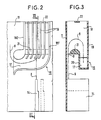
- Figures 2 and 3 respectively show two sections, one in front view and the other in left view of a rack for storage device according to the invention.
- Figure 4 shows a perspective view of a cassette for a storage device according to the invention.
- FIG. 1 The storage device presented in FIG. 1 is shown incorporated in a patching box 1, of the wall cabinet type, closed by a door 2 with lateral hinges 3 and lockable by means of fixing screws 4.
- the patch box 1 receives optical cables 5, here by its base 6, these cables having, in known manner, not developed here, different destinations.
- the optical fibers 7 that these cables 5 comprise are conventionally dissociated from one another in the box 1, so as to be connected together according to the chosen patching arrangements.
- each bracket 10 serves for example as a support for two carrying strands 9 and for this purpose comprises two strand fixings by screws, in parallel conduits, the screws, directly accessible through the door opening of the box, being offset l on the one hand compared to the other.
- connection between fibers 8 are made via connectors 12, here fixed parallel to one of the vertical sides of the box 1 on a support structure 13, these connectors 12 and this structure 13 not being developed here, because they are not directly related to the invention.
- the cassettes 14, of at least roughly parallelepiped shape are here aligned face against face on the floor and along the bottom wall 11 of the box, being fixed so as to be removable, for example by hooking or snap-fastening.
- the same fiber 8 emerges from the cassette through a mouth which opens towards the ceiling of the cabinet when this cassette is in place in the box. It then enters a storage bin 16 which is common to at least some, if not all, of the fibers.
- the rack 16 which is for example made of a molded material, is also detailed in FIGS. 2 and 3, it comprises a plurality of large and thin parallel boxes in each of which fibers each form a reserve loop, one of which from both ends exits through a common passage 0 positioned at one end of the boxes and here under the latter.
- the passage 0 is parallel to a conduit 17 leading to a lateral opening, here flared, which is common at least to several boxes and through which the other end of each of the loops stored in the rack 16 exits.
- the boxes are formed between parallel partitions 18 whose spacing is small, for example ten millimeters for boxes having a length of two hundred and twenty millimeters and a width of one hundred and ten millimeters.
- the partitions 18 are generally parallel to the large faces of the cassettes 14, above at least part of which the rack 16 is placed in the box 1, the ceiling of the rack 16 being formed by, or pressed against , at least part of the ceiling of cabinet 1.
- the opening of the conduit 17 is essentially delimited by the two partitions 18E and 18F, extremes, of the rack 16 - Figure 2 -.
- One of these two extreme partitions, 18F which comes here to be pressed against one of the two sides of the box 1, bends, in a first direction, to come to form the floor of the conduit passing under the curved ends, but more short, intermediate partitions 18, then in an opposite direction to form the flared opening in connection with the corresponding end of the other extreme partition 18E.
- the latter is here wound on itself in the first direction indicated above at this corresponding end, the radii of curvature of the ends of the various partitions 18 at the mouth being chosen as a function of the minimum radius of curvature R admissible for fibers 8.
- the flaring of the mouth which is determined by the opposite windings of the ends of the extreme partitions is placed laterally at one end of the rack 16 which is here located at the bottom of this rack in the box 1. It allows a large variation in orientation , inside the box 1, of the two ends of the fibers whose loops are stored in the rack 16.
- the sectional view along III-III of Figure 3 shows that the rack 16 is closed by two parallel walls on its front face and on its rear face.
- One of these two walls is for example constituted by the bottom wall 11 of the box 1, while the other is a plate 19, attached and preferably transparent; this plate 19 is located on the side of the door opening in the box 1, it covers the corresponding edge of the various partitions 18, on this side, and it is preferably removable to allow insertion of the loops in the boxes.
- FIG. 3 shows that the duct 17, the bottom of which is formed by the extension of the extreme partition 18F under the other partitions, as described above, extends only over part of the width of the rack 16 being limited by a rim 20 which extends parallel to the plate 19, at at least approximately half the width of the rack, along the length of the conduit 17 and, in height, above the bottom of the intermediate partitions 18, relative to the bottom of the conduit.
- the rim 20 is itself longitudinally bordered by an additional thickness 21 which here is semi-cylindrical and offset laterally towards the bottom wall 11 relative to the rim, when the rack 16 is in place in the box 1.
- This additional thickness 21 runs throughout the rack 16 and serves to secure all the partitions 18, to each other, in association with a longitudinal tab 22 running here at the top of the partitions.
- the extra thickness 21 also has a radius of curvature which is a function of the radius of curvature R admissible for the fibers and it borders the passage 0 which is formed between the bottom wall 11 of the box when the rack 16 is in place and itself , as seen in Figure 3.
- cassettes 14 are associated with the rack 16, being placed at a lower level of the box 1 relative to the latter. These cassettes 14 conventionally make it possible to store additional reserves of fibers 8, in particular downstream of the cable glands 7 when the fibers are recovered at this level, in the box 1.
- FIG. 4 An example of such a cassette 14 is presented in FIG. 4, it makes it possible to have two storage housings intended each to receive a portion of at least one optical fiber, the two ends of which exit from the cassette.
- the cassette is provided with a separation structure which is here a median wall 32, on either side of which the two storage housings are formed. It is also possible to produce this separation structure in the form of an openwork frame, not shown, on either side of which the two storage housings are arranged.
- each of these two housings is in the form of an at least roughly annular-looking duct formed between an element 33, called the minimum loop winding limit, and a peripheral border 34, l one and the other projecting on either side of the partition wall 32.
- the limiting element 33 is here constituted by a cylindrical structure which extends on either side of the partition wall with which it is here molded in a single block.
- the limiting element 33 is also capable of being produced in a different way, for example in the form of a plurality of studs arranged at least roughly circularly on either side of the partition wall 32, from the moment or it limits, to a predetermined minimum value, the reduction of a loop of fiber which comes to grip it, when the fiber is pulled towards the outside of the housing where it is coiled; this predetermined value corresponding by example with the minimum admissible radius of curvature for the fibers to be used.
- Each of the two conduits formed on either side of the partition wall 32 which is here laterally delimited by the peripheral edge 34 and by the limiting element 33 with which are possibly associated some guide pads 35 for the fiber, is also overhung by fiber holding teeth 36, such as 36A, 36B, 36C, 36D.
- teeth 36 are here parallel to the partition wall 32 at a level which corresponds to the level of projection of the cylindrical structure on either side of the partition wall.
- Each tooth partially closes one of the conduits which it overhangs between the peripheral edge 34 from which they originate and the limiting element 33, so as to prevent a lateral exit of a fiber out of this conduit.
- peripheral grooves 37 are formed in the cylindrical structure of the limiting element 33 facing the free ends of the teeth 36 which are partially introduced therein.
- each tooth 6 is associated with a cutout 38 of the same shape which is parallel to it in the partition wall, such as 38A, 38B, 38C, 38D to 36A, 36B, 36C and 36D.
- a fiber passage is made to make the two housings of a cassette communicate, it is here constituted by a slot 39 formed in the partition wall 32 flush with the cylindrical structure of the limiting element 33 on one side where this structure is offset longitudinally towards the peripheral edge so that the conduits are of narrower width at this level than the other where the possibilities of deployment of the fiber are increased by the significant widening of the conduit in each housing.
- the slot 39 extends over one of the possible fiber paths along the limit element 33, it ensures immobilization by wedging each fiber relative to to the cassette which makes it possible to have two reserves of fibers, in the housings, on either side of the slot for the two parts of each fiber which are located on either side of this slot.
- a slot 40 is formed in the partition wall 3, it ends transversely in the middle part of the slot 39 and opens onto the outside of the cassette to allow the introduction of a fiber transversely into slot 39 from the outside.
- the fibers 8 are immobilized at the level of the slot 39, for example by lining the fibers with stop collars, not shown, which come to grip them and which cannot pass through the slot 39 because of their dimensions or by a clamping collar 45 fixing them to element 3.
- Elements 46 forming a cover and here transparent, are placed on either side of the cassette to complete the obturation of the conduits in addition to the teeth, in particular at the level of the widest part of the conduits stored to prevent a part of the fiber stored in the housings does not exit laterally out of the cassette outside the mouths 41, 42, 43 provided for this purpose.
- the mouths 41, 42 are here formed in the peripheral border 34, each for a different housing, at a different end of the cassette on either side of the partition wall 32, flush with which they are located and along from which they open, possibly by several openings as can be seen on the right-hand side of FIG. 4 for the mouth 41.
- the mouth 43 is here constituted by a single opening formed in the peripheral border on the same side of the partition wall 32 as the mouth 41 and laterally, between the two ends where the mouths 41, 42 open and on the side to that which carries hooks 44 for fixing the cassette to the box 1.
- a fiber 8 into a cassette is preferably carried out by pushing the fiber between the free ends of the teeth 36 and the cylindrical structure of the limiting element 33, at the level of the peripheral grooves 37.
- This fiber 8 then preferably forms a single loop in each housing by entering it for example through the mouth 43 and exiting through the mouth 42 after having passed through the partition wall 32 through the slots 39, 40.
- Each fiber loop 1 is capable of taking a maximum extension in the duct of a housing which contains it, it then runs along the peripheral edge 34 and then makes it possible to obtain a maximum reserve for the part of fiber which comprises it.
- a pull, from the outside of the cassette, on this part of fiber then makes it possible to extract the portion in reserve through the mouth it crosses, the extension of the corresponding loop reducing until the moment when this loop is pressed against the limit element 33.
- the reintroduction of a portion of extracted fiber is intended to be achievable by simple pushing on the fiber in the direction of reintroduction through the mouth from which it comes out.
- This reintroduction is intended to be carried out by itself taking advantage of the relative rigidity of the fiber, in particular when the latter is moreover fixed relative to a location which the cassette is brought closer to, as happens in the case cassettes 14 in the box 1, when a cassette is replaced after being extracted. Likewise, the extraction of the fibers by pulling and the reinsertion by pushing are provided with the rack 16.
Abstract
Description
L'invention concerne le stockage des réserves, ou mous, qu'il est nécessaire de laisser aux fibres optiques, par exemple à leurs extrémités pour leur raccordement, en particulier dans les coffrets de brassage où ces fibres aboutissent.The invention relates to the storage of reserves, or soft, which it is necessary to leave to the optical fibers, for example at their ends for their connection, in particular in the patch boxes where these fibers end up.
Le brassage des fibres optiques de télécommunications s'effectue souvent dans des coffrets contenant d'une part des dispositifs de raccordement et de brassage, d'autre part des dispositifs de stockage de fibre contenant les réserves nécessaires aux raccordements présents ou futurs et aux modifications de brassage.The mixing of telecommunications optical fibers is often carried out in boxes containing on the one hand connection and patching devices, on the other hand fiber storage devices containing the reserves necessary for present or future connections and for modifications of brewing.
Le stockage des réserves de fibres en service s'effectue notamment au moyen de cassettes dans lesquelles les fibres sont partiellement lovées.The storage of fiber reserves in service is carried out in particular by means of cassettes in which the fibers are partially coiled.
Chaque cassette est prévue pour contenir une réserve d'une ou plusieurs boucles pour une ou plusieurs fibres, chaque réserve est extractible par traction sur l'une au moins des parties, sortant de la cassette, de la fibre à laquelle elle appartient.Each cassette is designed to contain a reserve of one or more loops for one or more fibers, each reserve is extractable by traction on at least one of the parts, leaving the cassette, of the fiber to which it belongs.
La réserve maximale, pour une fibre dans une cassette, est obtenue lorsque le déploiement de la ou des boucles qui la composent est maximal, les tractions sur la fibre depuis l'extérieur de la cassette tendant à réduire ce déploiement et par conséquent la réserve disponible.The maximum reserve, for a fiber in a cassette, is obtained when the deployment of the loop or loops which compose it is maximum, the pulls on the fiber from outside the cassette tend to reduce this deployment and therefore the available reserve .
La réintroduction d'une portion d'une réserve de fibre à l'intérieur d'une cassette, après traction sur la fibre, est généralement difficile à réaliser lorsqu'elle doit s'effectuer par simple poussée axiale de réintroduction sur la portion sortie de fibre.The reintroduction of a portion of a fiber reserve inside a cassette, after traction on the fiber, is generally difficult to achieve when it must be carried out by simple axial reintroduction push on the output portion of fiber.
En effet, la reconstitution des boucles, à leur plein déploiement, à l'intérieur d'une cassette s'effectue souvent incorrectement, lorsqu'il n'est pas possible d'intervenir directement à l'intérieur de la cassette pour réarranger les fibres.Indeed, the reconstruction of the loops, when fully deployed, inside a cassette is often performed incorrectly, when it is not possible to intervene directly inside the cassette to rearrange the fibers .
Or, dans de nombreux coffrets, les cassettes de stockage sont empilées ou accolées de manière déterminée et ne permettent pas les interventions de réarrangement qui seraient souhaitables, lorsqu'elles sont elles-mêmes en place.However, in many boxes, the storage cassettes are stacked or joined in a determined manner and do not allow the rearrangement interventions which would be desirable, when they are themselves in place.
Dans ces conditions, les réserves stockées dans les cassettes sont parfois insuffisantes, en particulier si la même longueur de réserve d'une fibre est exploitée d'une part pour les opérations d'extraction d'une cassette qui la contient, hors de l'ensemble de cassettes empilées ou accolées dont cette cassette fait partie, et d'autre part lors d'opérations successives de raccordement et/ou de brassage.Under these conditions, the reserves stored in the cassettes are sometimes insufficient, in particular if the same length of reserve of a fiber is used on the one hand for the operations of extraction from a cassette which contains it, outside the set of stacked or joined cassettes of which this cassette is a part, and on the other hand during successive operations of connection and / or mixing.
La présente invention propose donc un dispositif de stockage partiel de fibres optiques, en particulier pour coffret de brassage, qui soit apte à contenir en réserve des parties de fibres en service, dont il permet l'extraction et la rentrée individuelles.The present invention therefore provides a device for the partial storage of optical fibers, in particular for a brewing box, which is capable of containing in reserve parts of fibers in service, from which it allows individual extraction and re-entry.
Selon une caractéristique de l'invention, ce dispositif de stockage partiel de fibres optiques, comporte un casier de stockage comprenant une pluralité de cases parallèles dans lesquelles des fibres viennent former chacune une boucle de réserve dont l'une des deux extrémités sort par un passage commun positionné à une extrémité des cases, parallèlement à un conduit menant à une ouverture latérale commune de sortie pour l'autre extrémité de chaque boucle.According to a characteristic of the invention, this partial storage device for optical fibers, comprises a storage bin comprising a plurality of parallel boxes in which fibers each form a reserve loop, one of the two ends of which exits through a passage common positioned at one end of the boxes, parallel to a conduit leading to a common lateral outlet opening for the other end of each loop.
L'invention, ses caractéristiques et ses avantages sont précisés dans la description qui suit, en liaison avec les figures répertoriées ci-dessous.The invention, its characteristics and its advantages are explained in the following description, in conjunction with the figures listed below.
La figure 1 présente un coffret de brassage doté d'un dispositif de stockage selon l'invention, en perspective.Figure 1 shows a brewing box with a storage device according to the invention, in perspective.
Les figures 2 et 3 présentent respectivement deux coupes, l'une en vue de face et l'autre en vue de gauche d'un casier pour dispositif de stockage selon l'invention.Figures 2 and 3 respectively show two sections, one in front view and the other in left view of a rack for storage device according to the invention.
La figure 4 présente une vue en perspective d'une cassette pour dispositif de stockage selon l'invention.Figure 4 shows a perspective view of a cassette for a storage device according to the invention.
Le dispositif de stockage présenté en figure 1 est montré incorporé dans un coffret de brassage 1, de type armoire murale, fermé par une porte 2 à gonds latéraux 3 et verrouillable à l'aide de vis de fixation 4.The storage device presented in FIG. 1 is shown incorporated in a patching box 1, of the wall cabinet type, closed by a
Le coffret de brassage 1 reçoit des câbles optiques 5, ici par sa base 6, ces câbles ayant, de manière connue, non développée ici, des destinations différentes. Les fibres optiques 7 que comportent ces câbles 5 sont classiquement dissociées les unes des autres dans le coffret 1, afin d'être raccordées entre elles selon les dispositions de brassage choisies.The patch box 1 receives optical cables 5, here by its
A cet effet, les câbles 5 qui traversent la base 6 du coffret par l'intermédiaire de presse-étoupes 7, sont ouverts de manière à séparer les fibres du brin porteur 9 qui les accompagne, ce dernier étant suspendu par une extrémité à un potence 10 ici fixée sur la paroi de fond 11 du coffret. Chaque potence 10 sert par exemple de support pour deux brins porteurs 9 et comporte à cet effet deux fixations de brin par des vis, dans des conduits parallèles, les vis, directement accessibles au travers de l'ouverture de porte du coffret, étant décalées l'une part rapport à l'autre.For this purpose, the cables 5 which pass through the
Les raccordements entre fibres 8 s'effectuent par l'intermédiaire de connecteurs 12, ici fixés parallèlement à l'un des côtés verticaux du coffret 1 sur une structure de support 13, ces connecteurs 12 et cette structure 13 n'étant pas développés ici, car ils n'ont pas de rapport direct avec l'invention.The connections between
Chaque fibre 8 éventuellement regainée, à ce niveau et jusqu'au connecteur 12 où elle aboutit, traverse une cassette de stockage 14 dans laquelle elle est partiellement lovée afin de former une réserve.Each
Les cassettes 14, d'allure au moins grossièrement parallélépipédique, sont ici alignées face contre face sur le plancher et le long de la paroi de fond 11 du coffret, étant fixées de manière à être amovibles, par exemple par accrochage ou encliquetage.The
La description d'une de ces cassettes sera précisée plus loin en liaison avec la figure 4.The description of one of these cassettes will be specified below in conjunction with FIG. 4.
Dans l'exemple de réalisation proposé, chaque fibre 8 qui est issue d'un câble 5, s'en sépare lorsqu'il est éclaté, au-dessus du presse-étoupe 7 d'où il sort dans le coffret 1; cette fibre pénètre ensuite dans une cassette 14 par un orifice 15 ici montré disposé sur un côté de cassette 14 qui est destiné à être placé à l'avant du coffret et qui est donc directement accessible au travers de l'ouverture de porte du coffret.In the proposed embodiment, each
La même fibre 8 ressort de la cassette par une embouchure qui s'ouvre vers le plafond de l'armoire lorsque cette cassette est en place dans le coffret. Elle pénètre ensuite dans un casier de stockage 16 qui est commun à au moins une partie des fibres, sinon à la totalité.The
Le casier 16, qui est par exemple réalisé en un matériau moulé, est aussi détaillé sur les figures 2 et 3, il comporte une pluralité de grandes et minces cases parallèles dans chacune desquelles des fibres viennent former chacune une boucle de réserve dont l'un des deux extrémités sort par un passage commun 0 positionné à une extrémité des cases et ici sous ces dernières. Le passage 0 est parallèle à un conduit 17 menant à une ouverture latérale, ici évasée, qui est commune au moins à plusieurs cases et par laquelle sort l'autre extrémité de chacune des boucles stockées dans le casier 16.The
Les cases sont ménagées entre des cloisons 18 parallèles dont l'espacement est faible, par exemple dix millimètres pour des cases ayant une longueur de deux cent vingt millimètres et une largeur de cent dix millimètres.The boxes are formed between
Dans l'exemple proposé, les cloisons 18 sont globalement parallèles aux grandes faces des cassettes 14, au dessus d'au moins une partie desquelles le casier 16 est placé dans le coffret 1, le plafond du casier 16 étant formé par, ou plaqué contre, au moins une partie du plafond du coffret 1.In the example proposed, the
L'ouverture du conduit 17 est essentiellement délimitée par les deux cloisons 18E et 18F, extrêmes, du casier 16 ― figure 2 ―. L'une de ces deux cloisons extrêmes, 18F, qui vient ici se plaquer contre l'un des deux côtés du coffret 1, se recourbe, dans un premier sens, pour venir former le plancher du conduit passant sous les extrémités courbes, mais plus courtes, des cloisons 18 intermédiaires, puis dans un sens opposé pour former l'ouverture évasée en liaison avec l'extrémité correspondante de l'autre cloison extrême 18E. Cette dernière est ici enroulée sur elle-même dans le premier sens indiqué ci-dessus à cette extrémité correspondante, les rayons de courbure des extrémités des différentes cloisons 18 au niveau de l'embouchure étant choisis en fonction du rayon minimal de courbure R admissible pour les fibres 8.The opening of the
L'évasement de l'embouchure qui est déterminé par les enroulements opposés des extrémités des cloisons extrêmes est placé latéralement à une extrémité du casier 16 qui est ici située au bas de ce casier dans le coffret 1. Il permet une grande variation d'orientation, à l'intérieur du coffret 1, des deux extrémités des fibres dont les boucles sont stockées dans le casier 16.The flaring of the mouth which is determined by the opposite windings of the ends of the extreme partitions is placed laterally at one end of the
La vue en coupe selon III-III de la figure 3 montre que le casier 16 est fermé par deux parois parallèles sur sa face avant et sur sa face arrière. L'une de ces deux parois est par exemple constituée par la paroi de fond 11 du coffret 1, alors que l'autre est une plaque 19, rapportée et préférablement transparente; cette plaque 19 est située du côté de l'ouverture de porte dans le coffret 1, elle couvre le bord correspondant des différentes cloisons 18, de ce côté, et elle est préférablement amovible pour permettre une insertion des boucles dans les cases.The sectional view along III-III of Figure 3 shows that the
La figure 3 montre que le conduit 17 dont le fond est constitué par le prolongement de la cloison extrême 18F sous les autres cloisons, comme décrit ci-dessus, ne s'étend que sur une partie de la largeur du casier 16 étant limité par un rebord 20 qui s'étend parallèlement à la plaque 19, à approximativement au moins mi-largeur de casier, sur la longueur du conduit 17 et, en hauteur, au-dessus du bas des cloisons 18 intermédiaires, par rapport au fond du conduit.FIG. 3 shows that the
Le rebord 20 est lui-même longitudinalement bordé par une surépaisseur 21 qui ici est demi-cylindrique et déportée latéralement vers la paroi de fond 11 par rapport au rebord, lorsque le casier 16 est en place dans le coffret 1.The
Cette surépaisseur 21 court tout au long du casier 16 et sert à assujettir toutes les cloisons 18, les unes aux autres, en association avec une languette longitudinale 22 courant ici au sommet des cloisons.This
La surépaisseur 21 a elle aussi un rayon de courbure qui est fonction du rayon de courbure R admissible pour les fibres et elle borde le passage 0 qui est ménagé entre la paroi de fond 11 du coffret lorsque le casier 16 est en place et elle-même, ainsi qu'on le voit sur la figure 3.The
Chaque fibre 8 venant d'une cassette 14, comme montré sur la figure 3, traverse le passage 0 entre la paroi de fond 11 du coffret 1 et le rebord 21 du casier 16, au niveau d'une case dans laquelle elle forme une boucle en U. Elle en ressort sous les cloisons 18 et 18E par l'évasement que forme les cloisons extrêmes 18E et 18F, que borde le rebord 20 et la plaque 19 et qui termine le conduit de l'embouchure 17, comme on le voit sur les figures 2 et 3. Comme indiqué plus haut, l'orientation d'une fibre 8 à raccorder à l'un des connecteurs 12 peut varier largement, sans inconvénient, en sortie du casier 16, via le conduit 17.Each
L' extension d'une boucle en U dans une case et par conséquent la réserve de fibre correspondante varie d'une valeur maximale par exemple initiale pour laquelle la boucle s'étend au maximum dans la case à une valeur nulle pour laquelle la boucle de fibre repose sur la surépaisseur semi-cylindrique 21, dans sa case.The extension of a U-shaped loop in a cell and consequently the corresponding fiber reserve varies from a maximum value, for example initial for which the loop extends as much as possible in the cell to a zero value for which the loop fiber rests on the
Dans la forme de réalisation proposée en figure 1, des cassettes 14 sont associées au casier 16, étant placées à un niveau inférieur du coffret 1 par rapport à ce dernier. Ces cassettes 14 permettent classiquement de stocker des réserves supplémentaires de fibres 8, notamment en aval des presse-étoupes 7 lorsque les fibres sont regainées à ce niveau, dans le coffret 1.In the embodiment proposed in FIG. 1,
Un exemple d'une telle cassette 14 est présenté en figure 4, il permet de disposer de deux logements de stockage destinés à recevoir chacun une portion d'au moins une fibre optique dont les deux extrémités sortent de la cassette.An example of such a
A cet effet, la cassette est dotée d'une structure de séparation qui est ici une paroi 32, médiane, de part et d'autre de laquelle sont ménagés les deux logements de stockage. Il est également possible de réaliser cette structure de séparation sous forme d'une ossature ajourée, non représentée, de part et d'autre de laquelle sont disposés les deux logements de stockage.To this end, the cassette is provided with a separation structure which is here a
Dans la forme de réalisation proposée, chacun de ces deux logements se présente sous la forme d'un conduit d'allure au moins grossièrement annulaire ménagé entre un élément 33, dit limite minimale d'enroulement de boucle, et une bordure périphérique 34, l'un et l'autre en saillie de part et d'autre de la paroi de séparation 32.In the proposed embodiment, each of these two housings is in the form of an at least roughly annular-looking duct formed between an
L'élément limite 33 est ici constitué par une structure d'allure cylindrique qui s'étend de part et d'autre de la paroi de séparation avec laquelle elle est ici moulée en un seul bloc. L'élément limite 33 est également susceptible d'être réalisé d'une manière différente par exemple sous la forme d'une pluralités de plots disposés au moins grossièrement circulairement de part et d'autre de la paroi de séparation 32, à partir du moment ou il limite, à une valeur minimale prédéterminée, la réduction d'une boucle de fibre qui vient l'enserrer, lorsque la fibre est tirée vers l'extérieur du logement où elle est lovée; cette valeur prédéterminée correspondant par exemple au rayon de courbure minimal admissible pour les fibres à employer.The
Chacun des deux conduits ménagés de part et d'autre de la paroi de séparation 32 qui est ici latéralement délimité par la bordure périphérique 34 et par l'élément limite 33 auxquels sont éventuellement associés quelques plots de guidage 35 pour la fibre, est aussi surplombé par des dents 36 de maintien de fibre, telles 36A, 36B, 36C, 36D.Each of the two conduits formed on either side of the
Ces dents 36 sont ici parallèles à la paroi de séparation 32 à un niveau qui correspond au niveau de saillie de la structure cylindrique de part et d'autre de la paroi de séparation. Chaque dent ferme partiellement l'un des conduits qu'elle surplombe entre la bordure périphérique 34 dont elles sont issues et l'élément limite 33, de manière à empêcher une sortie latérale d'une fibre hors de ce conduit.These
Dans la réalisation présentée où la cassette comporte un corps moulé, des gorges périphériques 37 sont ménagées dans la structure cylindrique de l'élément limite 33 face aux extrémités libres des dents 36 qui viennent partiellement s'y introduire. De même pour des raisons de moulage, chaque dent 6 est associée à une découpure 38 de même forme qui lui est parallèle dans la paroi de séparation, telles 38A, 38B, 38C, 38D à 36A, 36B, 36C et 36D.In the embodiment presented where the cassette comprises a molded body,
Un passage de fibre est réalisé pour faire communiquer les deux logements d'une cassette, il est ici constitué par une fente 39 ménagée dans la paroi de séparation 32 au ras de la structure cylindrique de l'élément limite 33 d'un côté où cette structure est décentrée longitudinalement vers la bordure périphérique de manière que les conduits soient de largeur plus réduite à ce niveau que de l'autre où les possibilités de déploiement de la fibre sont accrus par l'élargissement important du conduit dans chaque logement.A fiber passage is made to make the two housings of a cassette communicate, it is here constituted by a
La fente 39 s'étend sur l'un des trajets possibles de fibre le long de l'élément limite 33, elle assure une immobilisation par coincement de chaque fibre par rapport à la cassette ce qui permet de disposer de deux réserves de fibres, dans les logements, de part et d'autre de la fente pour les deux parties de chaque fibre qui se situent de part et d'autre de cette fente.The
Dans la réalisation proposée, une fente 40 est ménagée dans la paroi de séparation 3, elle aboutit transversalement dans la partie médiane de la fente 39 et s'ouvre sur l'extérieur de la cassette pour permettre l'introduction d'une fibre transversalement dans la fente 39 depuis l'extérieur.In the proposed embodiment, a
L'immobilisation des fibres 8 au niveau de la fente 39 s'effectue par exemple en garnissant les fibres de colliers d'arrêt, non représentés, qui viennent les enserrer et qui ne peuvent traverser la fente 39 en raison de leurs dimensions ou encore par un collier de bridage 45 les fixant à l'élément 3.The
Des éléments 46, formant couvercle et ici transparents, sont accolés de part et d'autre de la cassette pour compléter l'obturation des conduits en supplément des dents, notamment au niveau de la partie la plus large des conduits stockée pour éviter qu'une partie de fibre stockée dans les logements ne sorte latéralement hors de la cassette en dehors des embouchures 41, 42, 43 prévues à cet effet.
Les embouchures 41, 42 sont ici ménagées dans la bordure périphérique 34, chacune pour un logement différent, à une extrémité différente de la cassette de part et d'autre de la paroi de séparation 32, au ras de laquelle elles sont situées et le long de laquelle elles s'ouvrent, éventuellement par plusieurs ouvertures ainsi qu'on le voit sur la partie droite de la figure 4 pour l'embouchure 41. L'embouchure 43 est ici constituée par une seule ouverture ménagée dans la bordure périphérique du même côté de la paroi de séparation 32 que l'embouchure 41 et latéralement, entre les deux extrémités où s'ouvrent les embouchures 41, 42 et du côté à celui qui porte des crochets de fixation 44 de la cassette au coffret 1.The
L'introduction d'une fibre 8 dans une cassette est préférablement effectuée en poussant la fibre entre les extrémités libres des dents 36 et la structure cylindrique de l'élément limite 33, au niveau des gorges périphériques 37. Cette fibre 8 forme alors préférablement une seule boucle dans chaque logement en y pénétrant par exemple par l'embouchure 43 et en ressortant par l'embouchure 42 après être passée au travers de la paroi de séparation 32 par les fentes 39, 40.The introduction of a
Chaque boucle de fibre 1 est susceptible de prendre une extension maximale dans le conduit d'un logement qui la contient, elle longe alors la bordure périphérique 34 et permet alors d'obtenir une réserve maximale pour la partie de fibre qui la comporte. Une traction, depuis l'extérieur de la cassette, sur cette partie de fibre permet alors d'extraire la portion en réserve au travers de l'embouchure qu'elle traverse, l'extension de la boucle correspondante se réduisant jusqu'au moment où cette boucle est plaquée contre l'élément limite 33. La réintroduction d'une portion de fibre extraite est prévue pour être réalisable par simple poussée sur la fibre dans le sens de réintroduction au travers de l'embouchure d'où elle sort.Each fiber loop 1 is capable of taking a maximum extension in the duct of a housing which contains it, it then runs along the peripheral edge 34 and then makes it possible to obtain a maximum reserve for the part of fiber which comprises it. A pull, from the outside of the cassette, on this part of fiber then makes it possible to extract the portion in reserve through the mouth it crosses, the extension of the corresponding loop reducing until the moment when this loop is pressed against the
Cette réintroduction est prévue pour s'effectuer d'elle-même en profitant de la rigidité relative de la fibre, notamment lorsque celle-ci est par ailleurs fixée par rapport à un emplacement dont on rapproche la cassette, comme cela se passe dans le cas des cassettes 14 dans le coffret 1, lorsqu'une cassette est remise en place après avoir été extraite. De même l'extraction des fibres par traction et la réinsertion par poussée sont prévues avec le casier 16.This reintroduction is intended to be carried out by itself taking advantage of the relative rigidity of the fiber, in particular when the latter is moreover fixed relative to a location which the cassette is brought closer to, as happens in the case cassettes 14 in the box 1, when a cassette is replaced after being extracted. Likewise, the extraction of the fibers by pulling and the reinsertion by pushing are provided with the
Claims (8)
Applications Claiming Priority (2)
| Application Number | Priority Date | Filing Date | Title |
|---|---|---|---|
| FR8916814A FR2656114B1 (en) | 1989-12-19 | 1989-12-19 | OPTICAL FIBER STORAGE DEVICE, PARTICULARLY FOR BREWING BOX. |
| FR8916814 | 1989-12-19 |
Publications (2)
| Publication Number | Publication Date |
|---|---|
| EP0434530A1 true EP0434530A1 (en) | 1991-06-26 |
| EP0434530B1 EP0434530B1 (en) | 1994-05-18 |
Family
ID=9388695
Family Applications (1)
| Application Number | Title | Priority Date | Filing Date |
|---|---|---|---|
| EP19900403608 Expired - Lifetime EP0434530B1 (en) | 1989-12-19 | 1990-12-14 | Storage device for optical fibres more particularly for a distributing box |
Country Status (4)
| Country | Link |
|---|---|
| EP (1) | EP0434530B1 (en) |
| DE (1) | DE69009027T2 (en) |
| ES (1) | ES2055890T3 (en) |
| FR (1) | FR2656114B1 (en) |
Cited By (7)
| Publication number | Priority date | Publication date | Assignee | Title |
|---|---|---|---|---|
| EP0557189A1 (en) * | 1992-02-21 | 1993-08-25 | Alcatel Cable Interface | Cassette for optical fibers |
| WO1995007482A1 (en) * | 1993-09-08 | 1995-03-16 | N.V. Raychem S.A. | Optical fibre organizer |
| GB2287796A (en) * | 1994-03-24 | 1995-09-27 | Augat Limited | Tubular optical fibre guide for splice tray |
| US5530954A (en) * | 1995-01-13 | 1996-06-25 | Telect, Inc. | Telecommunication fiber optic patch panel shelf assembly |
| US5535298A (en) * | 1995-01-30 | 1996-07-09 | The Whitaker Corporation | Pedestal for fiber optic cable |
| FR2733843A1 (en) * | 1995-05-03 | 1996-11-08 | Alcatel Submarcom | ORGANIZER DEVICE FOR CONNECTING OPTICAL FIBER CABLES AND JUNCTION BOX FOR OPTICAL CABLES |
| CN105093451A (en) * | 2015-07-24 | 2015-11-25 | 华为技术有限公司 | Fiber division and distribution device and communication site |
Citations (3)
| Publication number | Priority date | Publication date | Assignee | Title |
|---|---|---|---|---|
| DE3530625A1 (en) * | 1985-08-28 | 1987-03-05 | Rose Walter Gmbh & Co Kg | Distributor housing for holding cable splices for optical waveguides |
| DE8809714U1 (en) * | 1988-07-29 | 1988-09-22 | Siemens Ag, 1000 Berlin Und 8000 Muenchen, De | |
| EP0341027A2 (en) * | 1988-05-02 | 1989-11-08 | Gte Control Devices Of Puerto Rico Incorporated | Fiber distribution panel |
Family Cites Families (1)
| Publication number | Priority date | Publication date | Assignee | Title |
|---|---|---|---|---|
| DE530625C (en) * | 1927-05-17 | 1931-07-30 | Julius Baggesen | Device for holding out vibrations caused by road traffic on buildings |
-
1989
- 1989-12-19 FR FR8916814A patent/FR2656114B1/en not_active Expired - Lifetime
-
1990
- 1990-12-14 EP EP19900403608 patent/EP0434530B1/en not_active Expired - Lifetime
- 1990-12-14 DE DE1990609027 patent/DE69009027T2/en not_active Expired - Fee Related
- 1990-12-14 ES ES90403608T patent/ES2055890T3/en not_active Expired - Lifetime
Patent Citations (3)
| Publication number | Priority date | Publication date | Assignee | Title |
|---|---|---|---|---|
| DE3530625A1 (en) * | 1985-08-28 | 1987-03-05 | Rose Walter Gmbh & Co Kg | Distributor housing for holding cable splices for optical waveguides |
| EP0341027A2 (en) * | 1988-05-02 | 1989-11-08 | Gte Control Devices Of Puerto Rico Incorporated | Fiber distribution panel |
| DE8809714U1 (en) * | 1988-07-29 | 1988-09-22 | Siemens Ag, 1000 Berlin Und 8000 Muenchen, De |
Cited By (13)
| Publication number | Priority date | Publication date | Assignee | Title |
|---|---|---|---|---|
| FR2687801A1 (en) * | 1992-02-21 | 1993-08-27 | Mars Actel | CASSETTE OF OPTICAL FIBERS. |
| US5311612A (en) * | 1992-02-21 | 1994-05-10 | Mars Actel | Cassette for optical fibers |
| EP0557189A1 (en) * | 1992-02-21 | 1993-08-25 | Alcatel Cable Interface | Cassette for optical fibers |
| US5764843A (en) * | 1993-09-08 | 1998-06-09 | N.V. Raychem S.A. | Optical fibre organizer |
| WO1995007482A1 (en) * | 1993-09-08 | 1995-03-16 | N.V. Raychem S.A. | Optical fibre organizer |
| GB2287796A (en) * | 1994-03-24 | 1995-09-27 | Augat Limited | Tubular optical fibre guide for splice tray |
| US5530954A (en) * | 1995-01-13 | 1996-06-25 | Telect, Inc. | Telecommunication fiber optic patch panel shelf assembly |
| US5535298A (en) * | 1995-01-30 | 1996-07-09 | The Whitaker Corporation | Pedestal for fiber optic cable |
| FR2733843A1 (en) * | 1995-05-03 | 1996-11-08 | Alcatel Submarcom | ORGANIZER DEVICE FOR CONNECTING OPTICAL FIBER CABLES AND JUNCTION BOX FOR OPTICAL CABLES |
| US5838871A (en) * | 1995-05-03 | 1998-11-17 | Alcatel Submarcom | Device for organizing optical fiber cable connections and optical cable joint box |
| AU714708B2 (en) * | 1995-05-03 | 2000-01-06 | Alcatel N.V. | Splicing box for submarine optical fibre |
| CN105093451A (en) * | 2015-07-24 | 2015-11-25 | 华为技术有限公司 | Fiber division and distribution device and communication site |
| CN105093451B (en) * | 2015-07-24 | 2018-10-30 | 华为技术有限公司 | One kind point fibre and power distribution equipment and communication site |
Also Published As
| Publication number | Publication date |
|---|---|
| DE69009027D1 (en) | 1994-06-23 |
| FR2656114B1 (en) | 1992-02-28 |
| FR2656114A1 (en) | 1991-06-21 |
| EP0434530B1 (en) | 1994-05-18 |
| ES2055890T3 (en) | 1994-09-01 |
| DE69009027T2 (en) | 1994-09-01 |
Similar Documents
| Publication | Publication Date | Title |
|---|---|---|
| EP0479226B1 (en) | Cassette for optical junction | |
| EP0185923B1 (en) | Support for optical-fibre connections | |
| FR2660077A1 (en) | CONNECTING HOUSING FOR OPTICAL FIBERS. | |
| EP0434530B1 (en) | Storage device for optical fibres more particularly for a distributing box | |
| FR2972434A1 (en) | FLEXIBLE FLAT FLAT PRODUCT STORAGE DEVICE | |
| FR2682488A1 (en) | OPTICAL FIBER MODULAR CABLES HEAD OF HIGH CAPACITY. | |
| FR2589606A1 (en) | FREE SERVICE BANKING APPARATUS | |
| FR2498766A1 (en) | OPTICAL FIBER CABLES CONNECTION BOX | |
| FR2811972A1 (en) | Method of assembly of steel strips to lift installation involves placing strips on reels for simultaneous feeding into place on lift cage | |
| EP2156229B1 (en) | Junction box for optical fibres, including sealing means | |
| FR2523352A1 (en) | MAGNETIC TAPE CASSETTE AND SYSTEM COMPRISING SUCH A CASSETTE | |
| WO2009112692A2 (en) | Reaction cuvette supply to an automatic analysis machine | |
| WO2023131672A1 (en) | Transfer box for transferring articles into a carboard box | |
| EP2327833B1 (en) | Device for protecting an elongated object such as a cable or a pipe | |
| FR2570196A1 (en) | Device for storing the terminal portions of optical fibres at the break-out (distribution) heads of multi-fibre cables. | |
| EP0645657B1 (en) | Connecting device for optical fibres | |
| FR2647029A1 (en) | AIR FILTER WITH A PLATE-SHAPED FILTER CARTRIDGE | |
| JPS62163003A (en) | Fiber storage device for glass fiber cable | |
| FR2548223A1 (en) | DEVICE FOR TRANSPORTING EMPTY COILS | |
| WO2016193483A1 (en) | Cassette for coiling optical fibre, apparatus and method implementing such a cassette | |
| FR2656113A1 (en) | FIBER OPTIC STORAGE ARRANGEMENT, IN PARTICULAR FOR A CONNECTION BOX. | |
| FR2566756A1 (en) | Cable coiling box | |
| EP2156228B1 (en) | Junction box for optical fibres | |
| EP2156231B1 (en) | Junction box for optical fibres | |
| WO2009001013A1 (en) | Supporting element for optical fibre splices |
Legal Events
| Date | Code | Title | Description |
|---|---|---|---|
| PUAI | Public reference made under article 153(3) epc to a published international application that has entered the european phase |
Free format text: ORIGINAL CODE: 0009012 |
|
| AK | Designated contracting states |
Kind code of ref document: A1 Designated state(s): DE ES FR GB IT SE |
|
| 17P | Request for examination filed |
Effective date: 19911218 |
|
| 17Q | First examination report despatched |
Effective date: 19920119 |
|
| GRAA | (expected) grant |
Free format text: ORIGINAL CODE: 0009210 |
|
| AK | Designated contracting states |
Kind code of ref document: B1 Designated state(s): DE ES FR GB IT SE |
|
| GBT | Gb: translation of ep patent filed (gb section 77(6)(a)/1977) |
Effective date: 19940516 |
|
| REF | Corresponds to: |
Ref document number: 69009027 Country of ref document: DE Date of ref document: 19940623 |
|
| ITF | It: translation for a ep patent filed |
Owner name: JACOBACCI CASETTA & PERANI S.P.A. |
|
| REG | Reference to a national code |
Ref country code: ES Ref legal event code: FG2A Ref document number: 2055890 Country of ref document: ES Kind code of ref document: T3 |
|
| EAL | Se: european patent in force in sweden |
Ref document number: 90403608.4 |
|
| PLBE | No opposition filed within time limit |
Free format text: ORIGINAL CODE: 0009261 |
|
| STAA | Information on the status of an ep patent application or granted ep patent |
Free format text: STATUS: NO OPPOSITION FILED WITHIN TIME LIMIT |
|
| 26N | No opposition filed | ||
| PGFP | Annual fee paid to national office [announced via postgrant information from national office to epo] |
Ref country code: ES Payment date: 19950906 Year of fee payment: 6 |
|
| PGFP | Annual fee paid to national office [announced via postgrant information from national office to epo] |
Ref country code: SE Payment date: 19960812 Year of fee payment: 7 |
|
| PGFP | Annual fee paid to national office [announced via postgrant information from national office to epo] |
Ref country code: DE Payment date: 19960814 Year of fee payment: 7 |
|
| PGFP | Annual fee paid to national office [announced via postgrant information from national office to epo] |
Ref country code: FR Payment date: 19960912 Year of fee payment: 7 |
|
| PGFP | Annual fee paid to national office [announced via postgrant information from national office to epo] |
Ref country code: GB Payment date: 19961011 Year of fee payment: 7 |
|
| PG25 | Lapsed in a contracting state [announced via postgrant information from national office to epo] |
Ref country code: ES Free format text: LAPSE BECAUSE OF THE APPLICANT RENOUNCES Effective date: 19961216 |
|
| PG25 | Lapsed in a contracting state [announced via postgrant information from national office to epo] |
Ref country code: GB Free format text: LAPSE BECAUSE OF NON-PAYMENT OF DUE FEES Effective date: 19971214 |
|
| PG25 | Lapsed in a contracting state [announced via postgrant information from national office to epo] |
Ref country code: SE Free format text: LAPSE BECAUSE OF NON-PAYMENT OF DUE FEES Effective date: 19971215 |
|
| PG25 | Lapsed in a contracting state [announced via postgrant information from national office to epo] |
Ref country code: FR Free format text: THE PATENT HAS BEEN ANNULLED BY A DECISION OF A NATIONAL AUTHORITY Effective date: 19971231 |
|
| GBPC | Gb: european patent ceased through non-payment of renewal fee |
Effective date: 19971214 |
|
| PG25 | Lapsed in a contracting state [announced via postgrant information from national office to epo] |
Ref country code: DE Free format text: LAPSE BECAUSE OF NON-PAYMENT OF DUE FEES Effective date: 19980901 |
|
| EUG | Se: european patent has lapsed |
Ref document number: 90403608.4 |
|
| REG | Reference to a national code |
Ref country code: FR Ref legal event code: ST |
|
| REG | Reference to a national code |
Ref country code: ES Ref legal event code: FD2A Effective date: 20010402 |
|
| PG25 | Lapsed in a contracting state [announced via postgrant information from national office to epo] |
Ref country code: IT Free format text: LAPSE BECAUSE OF NON-PAYMENT OF DUE FEES;WARNING: LAPSES OF ITALIAN PATENTS WITH EFFECTIVE DATE BEFORE 2007 MAY HAVE OCCURRED AT ANY TIME BEFORE 2007. THE CORRECT EFFECTIVE DATE MAY BE DIFFERENT FROM THE ONE RECORDED. Effective date: 20051214 |