EP0437063A2 - Instrument for securing a suture needle - Google Patents
Instrument for securing a suture needle Download PDFInfo
- Publication number
- EP0437063A2 EP0437063A2 EP90313758A EP90313758A EP0437063A2 EP 0437063 A2 EP0437063 A2 EP 0437063A2 EP 90313758 A EP90313758 A EP 90313758A EP 90313758 A EP90313758 A EP 90313758A EP 0437063 A2 EP0437063 A2 EP 0437063A2
- Authority
- EP
- European Patent Office
- Prior art keywords
- needle
- channel
- elongated
- instrument
- instrument according
- Prior art date
- Legal status (The legal status is an assumption and is not a legal conclusion. Google has not performed a legal analysis and makes no representation as to the accuracy of the status listed.)
- Granted
Links
Images
Classifications
-
- A—HUMAN NECESSITIES
- A61—MEDICAL OR VETERINARY SCIENCE; HYGIENE
- A61B—DIAGNOSIS; SURGERY; IDENTIFICATION
- A61B17/00—Surgical instruments, devices or methods, e.g. tourniquets
- A61B17/34—Trocars; Puncturing needles
- A61B17/3468—Trocars; Puncturing needles for implanting or removing devices, e.g. prostheses, implants, seeds, wires
-
- A—HUMAN NECESSITIES
- A61—MEDICAL OR VETERINARY SCIENCE; HYGIENE
- A61B—DIAGNOSIS; SURGERY; IDENTIFICATION
- A61B17/00—Surgical instruments, devices or methods, e.g. tourniquets
- A61B17/04—Surgical instruments, devices or methods, e.g. tourniquets for suturing wounds; Holders or packages for needles or suture materials
- A61B17/06—Needles ; Sutures; Needle-suture combinations; Holders or packages for needles or suture materials
- A61B17/062—Needle manipulators
-
- A—HUMAN NECESSITIES
- A61—MEDICAL OR VETERINARY SCIENCE; HYGIENE
- A61B—DIAGNOSIS; SURGERY; IDENTIFICATION
- A61B17/00—Surgical instruments, devices or methods, e.g. tourniquets
- A61B17/34—Trocars; Puncturing needles
-
- A—HUMAN NECESSITIES
- A61—MEDICAL OR VETERINARY SCIENCE; HYGIENE
- A61B—DIAGNOSIS; SURGERY; IDENTIFICATION
- A61B17/00—Surgical instruments, devices or methods, e.g. tourniquets
- A61B17/00234—Surgical instruments, devices or methods, e.g. tourniquets for minimally invasive surgery
- A61B2017/00349—Needle-like instruments having hook or barb-like gripping means, e.g. for grasping suture or tissue
Definitions
- This invention relates to instruments for holding suture needles.
- Known needle holders tend to be too bulky for use in restricted surgical site areas and unsuitable for insertion through a trocar sheath.
- the beveled surface preferably is inclined at other than 90° to the axis to point away from, and force the needle away from the lateral opening of the channel.
- the end part of the elongated arrangement comprises an effective plurality of beveled surfaces, such as V-shaped or concave surfaces, the latter conform to the shape of the needle and urge the needle to be clamped in a non-rotatable manner.
- the opening of the tubular member is transverse or lateral to the axis of the member, namely at 90° or any other smaller angle which permits suitable siting of the needle.
- the contour of the opening and the shape of the beveled surface(s) conform to the outer contour of the needle and effectively clamp the needle in a non-rotatable manner. If the elongated arrangement is tubular, the beveled surface(s) is formed by the surface of the rim of the tube.
- the configuration of angles between the beveled surface and two surfaces of the channel at 60° (first and second surfaces) has been found to orient a curved suture needle in the same orientation with respect to the elongated member.
- the contact surfaces formed in the elongated member and the engaging wedge segment form at least four and as many as six or more contact surfaces with a tubular engaging segment for fixedly positioning a curved suture needle in the same orientation each time the suture needle is grasped.
- Curved suture needles typically have an elliptically shaped cross sectional area with a series of grooves longitudinally formed in the surface of the needle.
- the generally cross-sectional elliptical shape of curved needles and the ridges longitudinally formed on the surface of the needle further facilitate the almost identical positioning of a curved suture needle when inserted and wedged in the channel of the present medical instrument.
- the ease of movement of the wedge across the channel during an endoscopic surgical procedure significantly decreases the time required by the surgeon for suturing.
- the instrument of FIG.1 includes an elongated member 101, such as a cylindrical tube, which is passed through the passageway of trocar sheath 102 and into the peritoneal cavity 103 of patient 104.
- the trocar sheath is inserted into the patient for performing a minimally invasive endoscopic surgical procedure such as an operative laparoscopic or pelviscopic procedure.
- the distal end of the elongated member includes a channel 105 for receiving curved suture needle 106, which is inserted into the peritoneal cavity with the elongated member or alternatively via another trocar sheath 107.
- Suture thread is connected to one end of the curved needle for suturing tissue together or closing the end of a tube severed in surgery.
- elongated member tube 101 Attached at the proximal end of elongated member tube 101 is handle 108 with a generally U-shaped spring 109 extending therefrom for manual operation by the surgeon.
- This spring is easily grasped between the thumb and fingers of the surgeon for operating a wedge 110 which operates across the channel for grasping and fixedly positioning the suture needle.
- FIG.2 Depicted in FIG.2 is a partial cross-sectional side view of distal end 201 of elongated member 101 of the needle driver instrument.
- Elongated member 101 comprises a 7-gauge stainless steel tube approximately 30.5cms (12") in length for insertion through a 5mm trocar sheath.
- the outside diameter of a 7-gauge stainless steel regular wall tube is approximately 0.46cms (0.180") with an inside diameter of 0.38cms (0.150").
- a cylindrically shaped hollow passageway 202 extends the entire length of the tube along longitudinal axis 203.
- Channel 105 is transversely cut in tube 101 and through passageway 202. As shown, the channel is cut such that four surfaces 204-207 are formed in the semi-cylindrical wall.
- a first contact surface 205 is substantially parallel to longitudinal axis 203 at a depth of 0.29cms (0.115") from the opening of the channel or the outer surface of tube 101.
- Second contact surface 204 forms an approximately 60° angle with longitudinal axis 203 with one end of the surface at the opening of the channel approximately 0.584cms (0.230") from the extreme distal end 208 of the tube.
- First contact surface 205 is approximately 0.13cms (0.050”) in length.
- the third contact surface 206 of the channel is approximately 0.495cms (0.195") in length and rises to a height of approximately 0.025cms (0.010") from the opening of channel 105.
- the fourth contact surface 207 of the channel rises at approximately a 45° angle with respect to the longitudinal axis to the outside surface of the elongated tube.
- the third and fourth contact surfaces 206 and 207 guide the curved suture needle 106 into position and/or contact with first and second contact surfaces 205 and 204 as shown.
- Suture needle 106 at a point approximately mid-point through its curvature exhibits an elliptically-shaped cross section 209 with a plurality of grooves 210 and 211 formed on the outer and inner arc surfaces of the needle, respectively.
- Wedge 110 comprises elongated segment 214 and an engaging segment 212 with beveled surface 213.
- the engaging segment such as a cylindrical rod or tube
- elongated segment 214 such as a cylindrical rod or linkage tube
- Engaging segment 212 is approximately 1.27cms (0.50") in length and is comprised of 9-gauge regular wall tubing having an outside dimension of 0.376cms (0.148") with an inside diameter of 0.3cms (0.118").
- Beveled surface 213 forms an angle of approximately 14° with respect to the longitudinal axis of the elongated member.
- the use of a tube for engaging segment 212 provide two separate contact areas for engaging curved suture needle 106.
- a second beveled surface 215 at approximately a 45° angle is formed at the distal end of the engaging segment to reduce the sharpness of the distal end of the engaging segment so as not to extend beyond the distal end of outer elongated tubular member 101 while in use.
- a circular radius 216 is formed at the very distal end of the engaging segment to prevent any possible injury or extension of the engaging segment from passageway 202.
- Elongated segment 214 is a stainless steel rod approximately 32.07cms (12.625") in length with an outside diameter of 0.317 cms (0.125").
- FIG.4 Depicted in FIG.4 is a top view of the distal end of elongated member 101 with curved suture needle 106 wedged in channel 105.
- Engaging segment 212 of the wedge forces curved suture needle 106 into contact with contact surfaces 204 and 205 of channel 105 and beveled surface 213 of the wedge.
- needle 106 forms an angle 401 such as approximately 90° with respect to longitudinal axis 203 as viewed from the top. Angle 401 forms but just one orientation that has been experimentally found to be preferred by surgeons performing endoscopic surgical procedures.
- FIG.5 Depicted in FIG.5 is a top view of the distal end of elongated member 101 with curved suture needle 106 in an alternative embodiment channel 501.
- needle forms an angle 502 such as approximately 45° with respect to longitudinal axis 203 as viewed from the top.
- Channel surfaces 503-506 are formed in elongated member 101 and beveled surface 507 of engaging segment 508 in the same manner as depicted in FIG.4, except the channel and beveled surface are cut at a 45° rather than a 90° orientation.
- This 90°, or 45° or less orientation of the channel is to be regarded as being laterally positioned, causes the pointed end of the suture needle to extend beyond distal end 509 of the elongated member for extremely limited space applications or when the surgeon simply wants the needle point to extend beyond distal end 509 for suturing.
- Any top view angular orientation is contemplated. However, this 45° angular orientation is preferred. Other combinations of top view and side view angular orientations are also contemplated depending on the preference of the surgeon.
- the handle comprises a second elongated tubular member 301 having a passageway 302 positioned about longitudinal axis 203 extending from the first elongated tubular member 101.
- the second tubular member comprises a series 6061 T-6 drawn aluminum tube, rough tumbled and anodized blue in colour having a 1.27cms (0.500”) outside diameter and an inside diameter of 0.94cms (0.370").
- the tube is approximately 8.26cms (3.250") in length with a plurality of threads 303 and 304 formed in the inside surface of the tube.
- the distal threads 303 are approximately O.95cms (0.375") in length, whereas proximal threads 304 extend approximately 1.27cms (0.500”) into the proximal end of the tube.
- An elongated slot 305 is longitudinally formed in the wall of tube 301 approximately 2.54cms (1") in length and 0.476cms (0.1875") in width at a distance of 0.95cms (0.375") from the distal end 306 of the second elongated tubular member.
- the proximal end 307 of cylindrical rod 214 is inserted into a larger diameter cylindrical tube 308 and soldered therein using silver solder 309.
- Cylindrical tube 308 is a series 300 stainless steel tube approximately 3.8cms (1.5") in length with an outside diameter of O.91cms (0.360”) and an inside diameter of 0.325cms (0.128"). Centered at approximately 1.9cms (0.750") from the distal end thereof is a 0.476cms (3/16") radial hole 327 extending to passageway 310 of the tube.
- the L-shaped distal end 311 of spring 109 is inserted through slot 305 of the handle tube and into the radial hole 327 of tube 308 for moving the wedge including rod segment 214 within the passageways of the handle and elongated members.
- Front cap 312 At the distal end of elongated cylindrical tube 301 is front cap 312 which screws into the passageway of tube handle 108.
- the proximal end of tube 101 is silver soldered to front cap 312.
- Front cap 312 is approximately 0.76cms (0.300") in length and is formed from type 301 stainless steel rod.
- the outside diameter of the cap is 1.59cms (0.625") with a 0.46cms (0.182”) inside diameter passageway therethrough.
- a plurality of threads 314 such as 7/16-20 threads with a maximum outside dimension of 1.09cms (0.430") are formed therein.
- End cap 313 is formed from a 1.27cms (0.500”) diameter stainless steel rod.
- the rod is approximately 1.9cms (0.75") in length with a threaded portion of, for example, 7/16-20 threads formed at the distal end thereof.
- the threads are approximately O.48cms (3/16") in length.
- a recess 318 of approximately O.48cms (3/16") in length with a 0.762cms (0.300”) diameter relief is formed therein to receive the proximal end 316 of the generally U-shaped spring which is formed into an eye around the relief area of the end cap.
- An internal passageway 319 of approximately O.317cms (0.125") is drilled and counter sunk through the longitudinal axis of the rod.
- a knurled portion 320 of 0.81cms (0.32") is formed on the proximal end cap for turning the cap into the handle tube 108.
- the generally U-shaped spring 109 of the handle is covered with a tubular plastic material 315 to facilitate easy handling of the spring.
- the surgical instrument is easily disassembled for cleaning and subsequent reuse due to the modular construction thereof.
- a similar medical instrument may be formed with 12-gauge tubing for the elongated member to facilitate use through a 3mm trocar.
- the channel formed at the distal end of the tube would start approximately 0.254cms (0.100") from the distal end with a maximum depth of 0.165cms (0.065”) extending up to 0.135cms (0.053") for the start of the fourth contact surface.
- Parallel contact surface 210 would be approximately 0.127cms (0.050") in length with third contact surface 206 being 0.127cms (0.05”) in length.
- the suture needle can be curved or straight. It is also contemplated that a coil compression spring be inserted in the tubular handle to force the wedge against a suture needle inserted in the channel. The coil spring would be compressed and released by manually activated lever assemblies.
Abstract
Description
- This invention relates to instruments for holding suture needles.
- U.S. Patent 2,363,334 describes a known form of surgical needle holder.
- In limited access endoscopic procedures, surgical instruments of limited size are required to be inserted through a trocar sheath, and it is extremely important that the needles, and particulary curved needles, be held efficiently. It is highly desirable that curved needles be constantly maintained in perfect alignment along their own curvature during suturing.
- Known needle holders tend to be too bulky for use in restricted surgical site areas and unsuitable for insertion through a trocar sheath.
- According to the present invention there is provided an instrument as defined in claim 1.
- In an embodiment in which the end part of the elongated arrangement comprises a single or coplanar beveled surface, and the opening is a channel, then the beveled surface preferably is inclined at other than 90° to the axis to point away from, and force the needle away from the lateral opening of the channel.
- In another embodiment in which the end part of the elongated arrangement comprises an effective plurality of beveled surfaces, such as V-shaped or concave surfaces, the latter conform to the shape of the needle and urge the needle to be clamped in a non-rotatable manner.
- The opening of the tubular member is transverse or lateral to the axis of the member, namely at 90° or any other smaller angle which permits suitable siting of the needle.
- In the embodiments, the contour of the opening and the shape of the beveled surface(s) conform to the outer contour of the needle and effectively clamp the needle in a non-rotatable manner. If the elongated arrangement is tubular, the beveled surface(s) is formed by the surface of the rim of the tube.
- The configuration of angles between the beveled surface and two surfaces of the channel at 60° (first and second surfaces) has been found to orient a curved suture needle in the same orientation with respect to the elongated member. The contact surfaces formed in the elongated member and the engaging wedge segment form at least four and as many as six or more contact surfaces with a tubular engaging segment for fixedly positioning a curved suture needle in the same orientation each time the suture needle is grasped.
- Curved suture needles typically have an elliptically shaped cross sectional area with a series of grooves longitudinally formed in the surface of the needle. The generally cross-sectional elliptical shape of curved needles and the ridges longitudinally formed on the surface of the needle further facilitate the almost identical positioning of a curved suture needle when inserted and wedged in the channel of the present medical instrument. The ease of movement of the wedge across the channel during an endoscopic surgical procedure significantly decreases the time required by the surgeon for suturing.
-
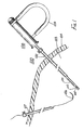
- FIG.1 depicts an embodiment instrument for holding suture needles;
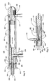
- FIG.2 depicts a cross-sectional side view of part of the instrument of FIG.1;
- FIG.3 depicts a partial cross-sectional side view of another part of the instrument of FIG.1;
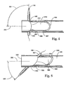
- FIG.4 depicts a top view of part of the instrument of FIG.1; and
- FIG.5 depicts a top view of part of an alternative embodiment instrument.
- The instrument of FIG.1 includes an
elongated member 101, such as a cylindrical tube, which is passed through the passageway oftrocar sheath 102 and into theperitoneal cavity 103 ofpatient 104. The trocar sheath is inserted into the patient for performing a minimally invasive endoscopic surgical procedure such as an operative laparoscopic or pelviscopic procedure. The distal end of the elongated member includes achannel 105 for receivingcurved suture needle 106, which is inserted into the peritoneal cavity with the elongated member or alternatively via anothertrocar sheath 107. Suture thread is connected to one end of the curved needle for suturing tissue together or closing the end of a tube severed in surgery. Attached at the proximal end ofelongated member tube 101 is handle 108 with a generallyU-shaped spring 109 extending therefrom for manual operation by the surgeon. This spring is easily grasped between the thumb and fingers of the surgeon for operating awedge 110 which operates across the channel for grasping and fixedly positioning the suture needle. - Depicted in FIG.2 is a partial cross-sectional side view of
distal end 201 ofelongated member 101 of the needle driver instrument. Elongatedmember 101 comprises a 7-gauge stainless steel tube approximately 30.5cms (12") in length for insertion through a 5mm trocar sheath. The outside diameter of a 7-gauge stainless steel regular wall tube is approximately 0.46cms (0.180") with an inside diameter of 0.38cms (0.150"). A cylindrically shapedhollow passageway 202 extends the entire length of the tube alonglongitudinal axis 203. Channel 105 is transversely cut intube 101 and throughpassageway 202. As shown, the channel is cut such that four surfaces 204-207 are formed in the semi-cylindrical wall. Afirst contact surface 205 is substantially parallel tolongitudinal axis 203 at a depth of 0.29cms (0.115") from the opening of the channel or the outer surface oftube 101.Second contact surface 204 forms an approximately 60° angle withlongitudinal axis 203 with one end of the surface at the opening of the channel approximately 0.584cms (0.230") from the extremedistal end 208 of the tube.First contact surface 205 is approximately 0.13cms (0.050") in length. - The
third contact surface 206 of the channel is approximately 0.495cms (0.195") in length and rises to a height of approximately 0.025cms (0.010") from the opening ofchannel 105. - The
fourth contact surface 207 of the channel rises at approximately a 45° angle with respect to the longitudinal axis to the outside surface of the elongated tube. The third andfourth contact surfaces curved suture needle 106 into position and/or contact with first andsecond contact surfaces needle 106 at a point approximately mid-point through its curvature exhibits an elliptically-shaped cross section 209 with a plurality ofgrooves - Wedge 110 comprises
elongated segment 214 and anengaging segment 212 withbeveled surface 213. The engaging segment, such as a cylindrical rod or tube, is silver soldered toelongated segment 214, such as a cylindrical rod or linkage tube, which extends throughpassageway 202 of elongatedtubular member 101 into the passageway ofhandle 108.Engaging segment 212 is approximately 1.27cms (0.50") in length and is comprised of 9-gauge regular wall tubing having an outside dimension of 0.376cms (0.148") with an inside diameter of 0.3cms (0.118").Beveled surface 213 forms an angle of approximately 14° with respect to the longitudinal axis of the elongated member. The use of a tube forengaging segment 212 provide two separate contact areas for engagingcurved suture needle 106. - A second
beveled surface 215 at approximately a 45° angle is formed at the distal end of the engaging segment to reduce the sharpness of the distal end of the engaging segment so as not to extend beyond the distal end of outer elongatedtubular member 101 while in use. Acircular radius 216 is formed at the very distal end of the engaging segment to prevent any possible injury or extension of the engaging segment frompassageway 202. - Elongated
segment 214 is a stainless steel rod approximately 32.07cms (12.625") in length with an outside diameter of 0.317 cms (0.125"). - When wedge 212 is operated toward the distal end of
passageway 202 withcurved suture needle 106 inchannel 105, the outer surface of the suture needle makes contact and is wedged againstchannel contact surfaces surface 213 of the wedge. A longitudinal force applied to the proximal end of the cylindrical rod forces the wedge toward the distal end ofelongated member 101 wedging the suture needle in an approximate 90° orientation with respect tolongitudinal axis 203 as shown. The angles, as specified, have been experimentally found to hold the suture needle with the greatest amount of force in the indicated, approximate right-angle orientation with respect to the elongated member. This orientation is preferred by surgeons performing operative laparoscopic procedures to enable them to form uniform sutures through the trocar sheath. However, the contact surface and beveled surface angles may be formed to provide the suture needle with any other side view angular orientation with respect tolongitudinal axis 203. - Depicted in FIG.4 is a top view of the distal end of
elongated member 101 withcurved suture needle 106 wedged inchannel 105.Engaging segment 212 of the wedge forcescurved suture needle 106 into contact withcontact surfaces channel 105 andbeveled surface 213 of the wedge. When wedged intochannel 105,needle 106 forms anangle 401 such as approximately 90° with respect tolongitudinal axis 203 as viewed from the top.Angle 401 forms but just one orientation that has been experimentally found to be preferred by surgeons performing endoscopic surgical procedures. - Depicted in FIG.5 is a top view of the distal end of
elongated member 101 withcurved suture needle 106 in analternative embodiment channel 501. When wedged intoalternative embodiment channel 501, needle forms anangle 502 such as approximately 45° with respect tolongitudinal axis 203 as viewed from the top. Channel surfaces 503-506 are formed inelongated member 101 andbeveled surface 507 ofengaging segment 508 in the same manner as depicted in FIG.4, except the channel and beveled surface are cut at a 45° rather than a 90° orientation. This 90°, or 45° or less orientation of the channel is to be regarded as being laterally positioned, causes the pointed end of the suture needle to extend beyonddistal end 509 of the elongated member for extremely limited space applications or when the surgeon simply wants the needle point to extend beyonddistal end 509 for suturing. Any top view angular orientation is contemplated. However, this 45° angular orientation is preferred. Other combinations of top view and side view angular orientations are also contemplated depending on the preference of the surgeon. - Depicted in FIG.3 is the proximal end of the instrument with
handle 108 and generallyU-shaped spring 109. The handle comprises a secondelongated tubular member 301 having apassageway 302 positioned aboutlongitudinal axis 203 extending from the firstelongated tubular member 101. The second tubular member comprises a series 6061 T-6 drawn aluminum tube, rough tumbled and anodized blue in colour having a 1.27cms (0.500") outside diameter and an inside diameter of 0.94cms (0.370"). The tube is approximately 8.26cms (3.250") in length with a plurality ofthreads distal threads 303 are approximately O.95cms (0.375") in length, whereasproximal threads 304 extend approximately 1.27cms (0.500") into the proximal end of the tube. Anelongated slot 305 is longitudinally formed in the wall oftube 301 approximately 2.54cms (1") in length and 0.476cms (0.1875") in width at a distance of 0.95cms (0.375") from thedistal end 306 of the second elongated tubular member. Theproximal end 307 ofcylindrical rod 214 is inserted into a larger diametercylindrical tube 308 and soldered therein usingsilver solder 309.Cylindrical tube 308 is a series 300 stainless steel tube approximately 3.8cms (1.5") in length with an outside diameter of O.91cms (0.360") and an inside diameter of 0.325cms (0.128"). Centered at approximately 1.9cms (0.750") from the distal end thereof is a 0.476cms (3/16")radial hole 327 extending topassageway 310 of the tube. The L-shapeddistal end 311 ofspring 109 is inserted throughslot 305 of the handle tube and into theradial hole 327 oftube 308 for moving the wedge includingrod segment 214 within the passageways of the handle and elongated members. - At the distal end of elongated
cylindrical tube 301 isfront cap 312 which screws into the passageway oftube handle 108. The proximal end oftube 101 is silver soldered tofront cap 312.Front cap 312 is approximately 0.76cms (0.300") in length and is formed fromtype 301 stainless steel rod. The outside diameter of the cap is 1.59cms (0.625") with a 0.46cms (0.182") inside diameter passageway therethrough. A plurality ofthreads 314 such as 7/16-20 threads with a maximum outside dimension of 1.09cms (0.430") are formed therein. -
End cap 313 is formed from a 1.27cms (0.500") diameter stainless steel rod. The rod is approximately 1.9cms (0.75") in length with a threaded portion of, for example, 7/16-20 threads formed at the distal end thereof. The threads are approximately O.48cms (3/16") in length. Arecess 318 of approximately O.48cms (3/16") in length with a 0.762cms (0.300") diameter relief is formed therein to receive theproximal end 316 of the generally U-shaped spring which is formed into an eye around the relief area of the end cap. Aninternal passageway 319 of approximately O.317cms (0.125") is drilled and counter sunk through the longitudinal axis of the rod. Aknurled portion 320 of 0.81cms (0.32") is formed on the proximal end cap for turning the cap into thehandle tube 108. - The generally
U-shaped spring 109 of the handle is covered with a tubularplastic material 315 to facilitate easy handling of the spring. The surgical instrument is easily disassembled for cleaning and subsequent reuse due to the modular construction thereof. A similar medical instrument may be formed with 12-gauge tubing for the elongated member to facilitate use through a 3mm trocar. In such instance, the channel formed at the distal end of the tube would start approximately 0.254cms (0.100") from the distal end with a maximum depth of 0.165cms (0.065") extending up to 0.135cms (0.053") for the start of the fourth contact surface.Parallel contact surface 210 would be approximately 0.127cms (0.050") in length withthird contact surface 206 being 0.127cms (0.05") in length. These dimensions would facilitate the preferred angles for securing a smaller curved suture needle. - The suture needle can be curved or straight. It is also contemplated that a coil compression spring be inserted in the tubular handle to force the wedge against a suture needle inserted in the channel. The coil spring would be compressed and released by manually activated lever assemblies.
Claims (12)
- An instrument for holding a suture needle (106), the instrument comprising a tubular member (101) with a transverse opening (105) therein proximate the distal end thereof, the opening serving to receive the needle, and an elongated arrangement (212,214) movable within and along the longitudinal axis of the tubular member and operable to exert a force on the needle and to thereby secure the latter in the opening, characterised in that the end of the elongated arrangement has a beveled surface inclined to said longitudinal axis and serving to exert a force on the needle in a direction inclined to the axis, thereby clamping the needle.
- An instrument according to claim 1, characterised in that the opening is a channel (105) with an entrance thereto for laterally receiving the needle, and in that the beveled surface is inclined so that the said force is exerted in a direction away from the said entrance.
- An instrument according to claim 2, characterised in that the interior of the channel is shaped to conform to the contour of part of the said needle, to minimize rotation of the needle.
- An instrument according to claim 3, characterised in that the said beveled surface is adapted to conform to the contour of another part of the said needle to further minimize the said rotation, and increase the clamping.
- An instrument according to claim 4, characterised in that the beveled surface is formed of a plurality of parts conforming to the contour(s) of the said other part of the needle.
- An instrument according to any one of claims 2 to 5, characterised in that the elongated arrangement is spring urged toward the channel, and is solid and/or tubular, and in that when the arrangement is tubular, the beveled surface is formed by the edge of a tube.
- An instrument according to any one of claims 2 to 6, characterised in that the channel has a first contact surface (205) substantially parallel to the longitudinal axis, and a second surface (204) at an acute angle with respect to the first surface, so as to form two clamping surfaces for the needle, a third clamping surface being provided by the said beveled surface.
- An instrument according to any one preceding claim, further characterised by a handle (108) attached to the proximal end of the instrument, and with a control member (109) for releasing and engaging the elongated arrangement.
- An instrument according to claim 8, characterised in that the control member is spring loaded (109) to urge the elongated arrangement along the tubular member and a handle passage into the clamped condition.
- An instrument according to claim 9, characterised in that the elongated arrangement includes a segment (214) movable within the tubular member and the passageway (101,312) of the handle.
- An instrument according to claim 9 or 10, characterised in that the control member is in the form of a hand operated spring with one end connected to the proximal end of the instrument and the other end movable to move the elongated segment.
- A medical instrument for driving a suture needle through tissue, comprising: an elongated member having a longitudinal passageway therein; a channel capable of receiving said needle and positioned in said elongated member about a distal end thereof and transverse through said passageway; and a wedge positioned within said passageway and operable across said channel to secure said needle between said elongated member and said wedge when said needle is positioned in said channel.
Applications Claiming Priority (2)
| Application Number | Priority Date | Filing Date | Title |
|---|---|---|---|
| US07/464,347 US5015250A (en) | 1990-01-12 | 1990-01-12 | Medical instrument for driving a suture needle |
| US464347 | 1990-01-12 |
Publications (3)
| Publication Number | Publication Date |
|---|---|
| EP0437063A2 true EP0437063A2 (en) | 1991-07-17 |
| EP0437063A3 EP0437063A3 (en) | 1991-08-21 |
| EP0437063B1 EP0437063B1 (en) | 1996-07-31 |
Family
ID=23843577
Family Applications (1)
| Application Number | Title | Priority Date | Filing Date |
|---|---|---|---|
| EP90313758A Expired - Lifetime EP0437063B1 (en) | 1990-01-12 | 1990-12-17 | Instrument for securing a suture needle |
Country Status (7)
| Country | Link |
|---|---|
| US (1) | US5015250A (en) |
| EP (1) | EP0437063B1 (en) |
| JP (1) | JP3131233B2 (en) |
| AT (1) | ATE140862T1 (en) |
| AU (1) | AU634848B2 (en) |
| CA (1) | CA2033563C (en) |
| DE (1) | DE69027980T2 (en) |
Cited By (10)
| Publication number | Priority date | Publication date | Assignee | Title |
|---|---|---|---|---|
| EP0740925A1 (en) * | 1991-12-03 | 1996-11-06 | Vesica Medical, Inc. | Suture passer |
| EP0746358A1 (en) * | 1993-08-30 | 1996-12-11 | Surgin Surgical Instrumentation, Inc. | Safety device for laparoscopic instruments |
| US5836314A (en) * | 1991-12-03 | 1998-11-17 | Boston Scientific Technology, Inc. | Surgical treatment of stress urinary incontinence |
| DE102009007722A1 (en) * | 2009-01-29 | 2010-08-26 | Karl Storz Gmbh & Co. Kg | Needle holder insert for medical instrument, comprises shaft, whose distal end is curved, and actuating element, which has stop, where primary side of medical needle is attached to stop, and has gripping element |
| US8033983B2 (en) | 2001-03-09 | 2011-10-11 | Boston Scientific Scimed, Inc. | Medical implant |
| US8162816B2 (en) | 2001-03-09 | 2012-04-24 | Boston Scientific Scimed, Inc. | System for implanting an implant and method thereof |
| US8602965B2 (en) | 2001-03-09 | 2013-12-10 | Boston Scientific Scimed, Inc. | System, methods and devices relating to delivery of medical implants |
| US8632453B2 (en) | 2002-12-17 | 2014-01-21 | Boston Scientific Scimed, Inc. | Spacer for sling delivery system |
| US8915927B2 (en) | 2001-03-09 | 2014-12-23 | Boston Scientific Scimed, Inc. | Systems, methods and devices relating to delivery of medical implants |
| US9149261B2 (en) | 2001-03-09 | 2015-10-06 | Boston Scientific Scimed, Inc. | Systems, methods and devices relating to delivery of medical implants |
Families Citing this family (96)
| Publication number | Priority date | Publication date | Assignee | Title |
|---|---|---|---|---|
| US5437680A (en) * | 1987-05-14 | 1995-08-01 | Yoon; Inbae | Suturing method, apparatus and system for use in endoscopic procedures |
| US5354298A (en) * | 1991-03-22 | 1994-10-11 | United States Surgical Corporation | Suture anchor installation system |
| CA2063159C (en) * | 1991-03-22 | 1999-06-15 | Thomas W. Sander | Orthopedic fastener |
| US5300082A (en) * | 1992-01-08 | 1994-04-05 | Sharpe Endosurgical Corporation | Endoneedle holder surgical instrument |
| US5628757A (en) * | 1992-02-04 | 1997-05-13 | Hasson; Harrith M. | Surgical instrument for holding a needle |
| AU4221193A (en) * | 1992-05-01 | 1993-11-29 | Li Medical Technologies, Inc. | Laparoscopic needle holder |
| US5312422A (en) * | 1992-07-16 | 1994-05-17 | Linvatec Corporation | Endoscopic suturing needle |
| US5387227A (en) * | 1992-09-10 | 1995-02-07 | Grice; O. Drew | Method for use of a laparo-suture needle |
| US5281237A (en) * | 1992-09-25 | 1994-01-25 | Gimpelson Richard J | Surgical stitching device and method of use |
| US5352219A (en) * | 1992-09-30 | 1994-10-04 | Reddy Pratap K | Modular tools for laparoscopic surgery |
| US5334196A (en) * | 1992-10-05 | 1994-08-02 | United States Surgical Corporation | Endoscopic fastener remover |
| AU5356894A (en) * | 1992-10-09 | 1994-05-09 | Li Medical Technologies, Inc. | Suture throw rundown tool |
| US5649939A (en) * | 1992-12-08 | 1997-07-22 | Reddick; Eddie J. | Laparoscopic suture introducer |
| US5403346A (en) * | 1992-12-31 | 1995-04-04 | Loeser; Edward A. | Self-affixing suture assembly |
| US5632753A (en) * | 1992-12-31 | 1997-05-27 | Loeser; Edward A. | Surgical procedures |
| US5330488A (en) * | 1993-03-23 | 1994-07-19 | Goldrath Milton H | Verres needle suturing kit |
| US5501691A (en) * | 1993-03-23 | 1996-03-26 | Goldrath; Milton H. | Verres needle suturing device |
| US5364410A (en) * | 1993-05-28 | 1994-11-15 | Ethicon, Inc. | Percutaneous suture externalizer |
| US5405354A (en) * | 1993-08-06 | 1995-04-11 | Vance Products Inc. | Suture driver |
| US5827299A (en) * | 1993-08-25 | 1998-10-27 | Inlet Medical, Inc | Insertable suture passing grasping probe and methodology for using same |
| US5507758A (en) * | 1993-08-25 | 1996-04-16 | Inlet Medical, Inc. | Insertable suture grasping probe guide, and methodology for using same |
| US5899911A (en) * | 1993-08-25 | 1999-05-04 | Inlet Medical, Inc. | Method of using needle-point suture passer to retract and reinforce ligaments |
| US5536273A (en) * | 1993-12-09 | 1996-07-16 | Lehrer; Theodor | Apparatus and method of extracorporeally applying and locking laparoscopic suture and loop ligatures |
| US5609597A (en) * | 1993-12-09 | 1997-03-11 | Lehrer; Theodor | Apparatus and method of extracorporeally applying and locking laparoscopic suture and loop ligatures |
| US5376096A (en) * | 1993-12-17 | 1994-12-27 | Vance Products Inc. | Medical instrument for driving a suture needle |
| CA2141911C (en) * | 1994-02-24 | 2002-04-23 | Jude S. Sauer | Surgical crimping device and method of use |
| US5454819A (en) * | 1994-03-17 | 1995-10-03 | Nusurg Medical, Inc. | Spring biased laparoscopic surgical needle holder |
| US5496332A (en) * | 1994-10-20 | 1996-03-05 | Cordis Corporation | Wound closure apparatus and method for its use |
| US5499991A (en) * | 1994-12-19 | 1996-03-19 | Linvatec Corporation | Endoscopic needle with suture retriever |
| US5643295A (en) | 1994-12-29 | 1997-07-01 | Yoon; Inbae | Methods and apparatus for suturing tissue |
| US5713908A (en) * | 1995-01-09 | 1998-02-03 | Jameel; Irfan Mufty | Laparascopic suturing instrument |
| US5643292A (en) * | 1995-01-10 | 1997-07-01 | Applied Medical Resources Corporation | Percutaneous suturing device |
| US5665096A (en) * | 1995-03-07 | 1997-09-09 | Yoon; Inbae | Needle driving apparatus and methods of suturing tissue |
| US5951575A (en) * | 1996-03-01 | 1999-09-14 | Heartport, Inc. | Apparatus and methods for rotationally deploying needles |
| US5746753A (en) * | 1996-05-13 | 1998-05-05 | Boston Scientific Corporation | Needle grasping apparatus |
| US5948000A (en) | 1996-10-03 | 1999-09-07 | United States Surgical Corporation | System for suture anchor placement |
| US5948001A (en) * | 1996-10-03 | 1999-09-07 | United States Surgical Corporation | System for suture anchor placement |
| CA2217435C (en) | 1996-10-04 | 2006-08-29 | United States Surgical Corporation | Tissue fastener implantation apparatus and method |
| CA2217406C (en) | 1996-10-04 | 2006-05-30 | United States Surgical Corporation | Suture anchor installation system with disposable loading unit |
| US5758665A (en) * | 1996-11-14 | 1998-06-02 | Suval; William D. | Method for treating varicose veins |
| DE19710432C2 (en) * | 1997-03-13 | 2002-08-14 | Wolf Gmbh Richard | needle holder |
| US5908426A (en) * | 1997-04-24 | 1999-06-01 | Pierce; Javin | Suture needle manipulator |
| US5843126A (en) * | 1997-08-15 | 1998-12-01 | Jameel; Irfan M. | Multiple surgical suture application |
| US6171316B1 (en) | 1997-10-10 | 2001-01-09 | Origin Medsystems, Inc. | Endoscopic surgical instrument for rotational manipulation |
| US5944739A (en) * | 1998-03-12 | 1999-08-31 | Surgical Dynamics, Inc. | Suture anchor installation system |
| US6723107B1 (en) | 1999-04-19 | 2004-04-20 | Orthopaedic Biosystems Ltd. | Method and apparatus for suturing |
| EP1289429B1 (en) | 2000-06-05 | 2006-03-15 | Boston Scientific Limited | devices for the treatment of urinary incontinence |
| US7037324B2 (en) | 2000-09-15 | 2006-05-02 | United States Surgical Corporation | Knotless tissue anchor |
| US6984237B2 (en) | 2002-05-22 | 2006-01-10 | Orthopaedic Biosystems Ltd., Inc. | Suture passing surgical instrument |
| US6936054B2 (en) | 2002-07-22 | 2005-08-30 | Boston Scientific Scimed, Inc. | Placing sutures |
| US7150753B2 (en) * | 2002-08-16 | 2006-12-19 | Om Prakash Rehil | Non-disposable trocar needle and handle |
| DE10255344A1 (en) * | 2002-11-27 | 2005-06-30 | Siemens Ag | Conveyor system for goods, in particular containers for luggage, and control system for the conveyor system |
| WO2004069291A2 (en) * | 2003-02-04 | 2004-08-19 | Lsi Solutions, Inc. | Instrument for assisting in the remote placement of tied surgical knots and trimming of suture away from the knot and method of use |
| WO2004112616A2 (en) * | 2003-06-16 | 2004-12-29 | Ortheon Medical Llc | Suture cutter |
| US7794471B1 (en) | 2003-06-26 | 2010-09-14 | Cardica, Inc. | Compliant anastomosis system |
| US8574246B1 (en) | 2004-06-25 | 2013-11-05 | Cardica, Inc. | Compliant anastomosis system utilizing suture |
| US7361138B2 (en) | 2003-07-31 | 2008-04-22 | Scimed Life Systems, Inc. | Bioabsorbable casing for surgical sling assembly |
| JP4954874B2 (en) | 2004-06-16 | 2012-06-20 | スミス アンド ネフュー インコーポレーテッド | Suture threader |
| US7883519B2 (en) * | 2004-07-06 | 2011-02-08 | Ran Oren | Suture manipulating instrument particularly useful with endoscopes |
| US8992549B2 (en) | 2004-08-05 | 2015-03-31 | Teleflex Medical Incorporated | Laparoscopic port site closure tool |
| US8123762B2 (en) | 2004-08-19 | 2012-02-28 | Boston Scientific Scimed, Inc. | Suturing instrument |
| US7883518B1 (en) | 2005-01-07 | 2011-02-08 | Cardica, Inc. | Surgical knot |
| US8172801B2 (en) * | 2005-09-15 | 2012-05-08 | Boston Scientific Scimed, Inc. | Method for positioning a catheter guide element in a patient and kit for use in said method |
| US20070106310A1 (en) * | 2005-11-10 | 2007-05-10 | Goldin Mark A | Suture cutter |
| US7806834B2 (en) * | 2006-03-07 | 2010-10-05 | Devicor Medical Products, Inc. | Device for minimally invasive internal tissue removal |
| US7670299B2 (en) * | 2006-03-07 | 2010-03-02 | Ethincon Endo-Surgery, Inc. | Device for minimally invasive internal tissue removal |
| US7465278B2 (en) * | 2006-03-29 | 2008-12-16 | Ethicon Endo-Surgery, Inc. | Device for minimally invasive internal tissue removal |
| EP2094167B1 (en) | 2006-11-30 | 2011-06-29 | Wilson-Cook Medical, Inc. | Visceral anchors for purse-string closure of perforations |
| US8142450B2 (en) * | 2007-03-13 | 2012-03-27 | Longevity Surgical, Inc. | Methods for reducing gastric volume |
| US8500777B2 (en) | 2007-03-13 | 2013-08-06 | Longevity Surgical, Inc. | Methods for approximation and fastening of soft tissue |
| EP2150183B1 (en) * | 2007-05-31 | 2013-03-20 | Cook Medical Technologies LLC | Suture lock |
| EP2178446B1 (en) * | 2007-08-17 | 2013-05-22 | Cook Medical Technologies LLC | Device to open and close a bodily wall |
| EP2230987B1 (en) * | 2008-01-03 | 2013-02-27 | Cook Medical Technologies LLC | Medical systems for endoscopically suturing perforations |
| US8926639B2 (en) | 2009-01-12 | 2015-01-06 | Teleflex Medical Incorporated | Apparatus and methods for tissue closure |
| WO2010115072A1 (en) | 2009-04-03 | 2010-10-07 | Wilson-Cook Medical, Inc. | Tissue anchors and medical devices for rapid deployment of tissue anchors |
| EP2429374B1 (en) * | 2009-05-01 | 2013-09-25 | Cook Medical Technologies LLC | Medical device for suturing perforations |
| US9138207B2 (en) | 2009-05-19 | 2015-09-22 | Teleflex Medical Incorporated | Methods and devices for laparoscopic surgery |
| MX2009006490A (en) * | 2009-06-17 | 2010-12-16 | Gomez Gonzalo Manuel Torres | Needle holder for laparoscopic surgery with an automatic clasp. |
| WO2011089565A1 (en) | 2010-01-20 | 2011-07-28 | EON Surgical Ltd. | System of deploying an elongate unit in a body cavity |
| US8721539B2 (en) | 2010-01-20 | 2014-05-13 | EON Surgical Ltd. | Rapid laparoscopy exchange system and method of use thereof |
| US20110190794A1 (en) * | 2010-01-29 | 2011-08-04 | Richard Wolf Gmbh | Medical needle holder |
| US20110224718A1 (en) * | 2010-03-10 | 2011-09-15 | Torgerson Clinton D | Surgical needle driver and method of making the same |
| CA2915912A1 (en) | 2010-09-10 | 2015-05-07 | Pivot Medical, Inc. | Method and apparatus for passing suture through tissue |
| US10098631B2 (en) | 2010-09-10 | 2018-10-16 | Pivot Medical, Inc. | Method and apparatus for passing suture through tissue |
| CN103298503A (en) | 2010-09-10 | 2013-09-11 | 皮沃特医疗公司 | Method and apparatus for passing suture through tissue |
| CN103220987B (en) | 2010-09-19 | 2016-05-18 | 意昂外科有限公司 | Miniature laparoscope and improvement thereof |
| US8556916B2 (en) | 2011-02-14 | 2013-10-15 | Smith & Nephew, Inc. | Method and device for suture manipulation |
| EP2800521B1 (en) | 2012-01-04 | 2020-03-04 | Teleflex Medical Incorporated | Apparatus for tissue closure |
| WO2013119592A1 (en) | 2012-02-07 | 2013-08-15 | Arthrocare Corporation | Surgical instrument for manipulating and passing suture |
| US10245021B2 (en) | 2013-10-08 | 2019-04-02 | Applied Medical Technology, Inc | Magnetic U-stitch device |
| US10765420B2 (en) | 2014-04-24 | 2020-09-08 | Smith & Nephew, Inc. | Suture passer |
| US9936943B1 (en) | 2014-08-07 | 2018-04-10 | Nicholas MANCINI | Suture passing surgical device with atraumatic grasper preventing accidental perforations |
| EP3531931A1 (en) | 2016-10-31 | 2019-09-04 | Smith & Nephew, Inc | Suture passer and grasper instrument and method |
| CN109770978A (en) * | 2018-11-26 | 2019-05-21 | 李峥 | A kind of annulus fibrosus disci intervertebralis stitching devices and method |
| CN112386296A (en) * | 2020-10-11 | 2021-02-23 | 德清创赢机械科技有限公司 | Surgical operation suture needle clamping device |
| WO2023215328A1 (en) * | 2022-05-02 | 2023-11-09 | Degregorio John | Wedge lock needle holder |
Citations (5)
| Publication number | Priority date | Publication date | Assignee | Title |
|---|---|---|---|---|
| US2348218A (en) * | 1942-04-09 | 1944-05-09 | Singer Mfg Co | Surgical stitching instrument |
| US2363334A (en) * | 1943-03-02 | 1944-11-21 | William O Jones | Surgical needle holder |
| US2370545A (en) * | 1943-09-03 | 1945-02-27 | Singer Mfg Co | Surgical stitching instrument for eye and plastic surgery |
| US2737954A (en) * | 1954-02-12 | 1956-03-13 | Gloria H Knapp | Surgical stitching instrument with rotatable needle support |
| US4597390A (en) * | 1984-04-02 | 1986-07-01 | Mulhollan James S | Surgical needle manipulator |
Family Cites Families (16)
| Publication number | Priority date | Publication date | Assignee | Title |
|---|---|---|---|---|
| US1539221A (en) * | 1923-10-30 | 1925-05-26 | Tennant John William | Welder's rod holder |
| US3871379A (en) * | 1971-08-26 | 1975-03-18 | Henry C N Clarke | Laparoscopy instruments and method for suturing and ligation |
| US3921640A (en) * | 1974-03-22 | 1975-11-25 | Int Paper Co | Disposable surgical instruments |
| JPS5542626A (en) * | 1978-09-20 | 1980-03-26 | Olympus Optical Co | Blocking device of coelom inside tubular portion |
| US4406237A (en) * | 1980-05-23 | 1983-09-27 | Janome Sewing Machine Co. Ltd. | Suturing instrument for surgical operation |
| JPS571332A (en) * | 1980-06-06 | 1982-01-06 | Janome Sewing Machine Co Ltd | Catching of needle yarn loop of operation suturing device |
| JPS6245693Y2 (en) * | 1981-03-20 | 1987-12-07 | ||
| JPS57170239A (en) * | 1981-04-13 | 1982-10-20 | Janome Sewing Machine Co Ltd | Holding of shuttle of suturing device for operation |
| US4424898A (en) * | 1982-04-08 | 1984-01-10 | Ethicon, Inc. | Needle and suture holder and package |
| US4524771A (en) * | 1982-10-28 | 1985-06-25 | Ethicon Inc. | Multiple curved surgical needle |
| US4491135A (en) * | 1982-11-03 | 1985-01-01 | Klein Harvey A | Surgical needle holder |
| US4827929A (en) * | 1983-08-29 | 1989-05-09 | Joseph Hodge | Angulated surgical instrument |
| US4572185A (en) * | 1984-02-23 | 1986-02-25 | Mark Rich | Nonplanar surgical needle holder and related suturing method |
| US4624252A (en) * | 1985-02-14 | 1986-11-25 | Sol Weiss | Surgical device |
| US4580567A (en) * | 1985-06-03 | 1986-04-08 | The United States Of America As Represented By The Secretary Of The Army | Suture needle holder |
| US4765334A (en) * | 1987-01-12 | 1988-08-23 | Sol Weiss | Surgical device for performing thoracostomies |
-
1990
- 1990-01-12 US US07/464,347 patent/US5015250A/en not_active Expired - Lifetime
- 1990-12-17 AT AT90313758T patent/ATE140862T1/en not_active IP Right Cessation
- 1990-12-17 EP EP90313758A patent/EP0437063B1/en not_active Expired - Lifetime
- 1990-12-17 DE DE69027980T patent/DE69027980T2/en not_active Expired - Lifetime
-
1991
- 1991-01-03 CA CA002033563A patent/CA2033563C/en not_active Expired - Fee Related
- 1991-01-07 AU AU69211/91A patent/AU634848B2/en not_active Ceased
- 1991-01-09 JP JP03011618A patent/JP3131233B2/en not_active Expired - Fee Related
Patent Citations (5)
| Publication number | Priority date | Publication date | Assignee | Title |
|---|---|---|---|---|
| US2348218A (en) * | 1942-04-09 | 1944-05-09 | Singer Mfg Co | Surgical stitching instrument |
| US2363334A (en) * | 1943-03-02 | 1944-11-21 | William O Jones | Surgical needle holder |
| US2370545A (en) * | 1943-09-03 | 1945-02-27 | Singer Mfg Co | Surgical stitching instrument for eye and plastic surgery |
| US2737954A (en) * | 1954-02-12 | 1956-03-13 | Gloria H Knapp | Surgical stitching instrument with rotatable needle support |
| US4597390A (en) * | 1984-04-02 | 1986-07-01 | Mulhollan James S | Surgical needle manipulator |
Cited By (15)
| Publication number | Priority date | Publication date | Assignee | Title |
|---|---|---|---|---|
| EP0740925A1 (en) * | 1991-12-03 | 1996-11-06 | Vesica Medical, Inc. | Suture passer |
| US5836314A (en) * | 1991-12-03 | 1998-11-17 | Boston Scientific Technology, Inc. | Surgical treatment of stress urinary incontinence |
| US5860425A (en) * | 1991-12-03 | 1999-01-19 | Boston Scientific Technology, Inc. | Bladder neck suspension procedure |
| EP0746358A1 (en) * | 1993-08-30 | 1996-12-11 | Surgin Surgical Instrumentation, Inc. | Safety device for laparoscopic instruments |
| EP0746358A4 (en) * | 1993-08-30 | 1998-12-16 | Surgin Surgical Instrumentatio | Safety device for laparoscopic instruments |
| US8033983B2 (en) | 2001-03-09 | 2011-10-11 | Boston Scientific Scimed, Inc. | Medical implant |
| US8162816B2 (en) | 2001-03-09 | 2012-04-24 | Boston Scientific Scimed, Inc. | System for implanting an implant and method thereof |
| US8602965B2 (en) | 2001-03-09 | 2013-12-10 | Boston Scientific Scimed, Inc. | System, methods and devices relating to delivery of medical implants |
| US8617048B2 (en) | 2001-03-09 | 2013-12-31 | Boston Scientific Scimed, Inc. | System for implanting an implant and method thereof |
| US8915927B2 (en) | 2001-03-09 | 2014-12-23 | Boston Scientific Scimed, Inc. | Systems, methods and devices relating to delivery of medical implants |
| US9149261B2 (en) | 2001-03-09 | 2015-10-06 | Boston Scientific Scimed, Inc. | Systems, methods and devices relating to delivery of medical implants |
| US10117733B2 (en) | 2001-03-09 | 2018-11-06 | Boston Scientific Scimed, Inc. | Systems, methods and devices relating to delivery of medical implants |
| US8632453B2 (en) | 2002-12-17 | 2014-01-21 | Boston Scientific Scimed, Inc. | Spacer for sling delivery system |
| DE102009007722A1 (en) * | 2009-01-29 | 2010-08-26 | Karl Storz Gmbh & Co. Kg | Needle holder insert for medical instrument, comprises shaft, whose distal end is curved, and actuating element, which has stop, where primary side of medical needle is attached to stop, and has gripping element |
| DE102009007722B4 (en) * | 2009-01-29 | 2017-09-14 | Karl Storz Gmbh & Co. Kg | Needle holder insert for flexible medical instruments |
Also Published As
| Publication number | Publication date |
|---|---|
| EP0437063B1 (en) | 1996-07-31 |
| DE69027980D1 (en) | 1996-09-05 |
| CA2033563C (en) | 2001-04-10 |
| DE69027980T2 (en) | 1996-11-28 |
| JP3131233B2 (en) | 2001-01-31 |
| ATE140862T1 (en) | 1996-08-15 |
| CA2033563A1 (en) | 1991-07-13 |
| AU634848B2 (en) | 1993-03-04 |
| EP0437063A3 (en) | 1991-08-21 |
| US5015250A (en) | 1991-05-14 |
| AU6921191A (en) | 1991-07-18 |
| JPH04212337A (en) | 1992-08-03 |
Similar Documents
| Publication | Publication Date | Title |
|---|---|---|
| EP0437063B1 (en) | Instrument for securing a suture needle | |
| US5376096A (en) | Medical instrument for driving a suture needle | |
| EP0669103B1 (en) | Surgical crimping device | |
| AU712129B2 (en) | Needle driving apparatus and methods of suturing tissue | |
| US6224614B1 (en) | Suturing instrument with angled needle holder and method for use thereof | |
| US5520702A (en) | Method and apparatus for applying a cinch member to the ends of a suture | |
| US5893877A (en) | Surgical instrument with offset handle | |
| US5405354A (en) | Suture driver | |
| US5009643A (en) | Self-retaining electrically insulative trocar sleeve and trocar | |
| US5964773A (en) | Laparascopic suturing device and suture needles | |
| US6086601A (en) | Instrument and method for suturing anatomical tissue and tying suture material | |
| US8696688B2 (en) | Method and apparatus for passing a flexible strand | |
| US5480405A (en) | Anchor applier instrument for use in suturing tissue | |
| US4784139A (en) | Needle guide instrument | |
| EP0702933A1 (en) | Manipulating and anchoring tissue | |
| US20040087978A1 (en) | Surgical fascia closure instrument, guide and method | |
| US6638265B1 (en) | Laparoscopy cannula adapter and assembly | |
| US9301748B2 (en) | Suture apparatus, system and method | |
| US10660636B2 (en) | Suture apparatus, system and method | |
| US5843039A (en) | Surgical treatment | |
| US5417702A (en) | Surgical cutting device | |
| US7150753B2 (en) | Non-disposable trocar needle and handle | |
| US20150374359A1 (en) | Suture apparatus, system and method | |
| WO1997037594A1 (en) | Laparascopic suturing device and suture needles | |
| US20030183545A1 (en) | Surgical syringe holder |
Legal Events
| Date | Code | Title | Description |
|---|---|---|---|
| PUAI | Public reference made under article 153(3) epc to a published international application that has entered the european phase |
Free format text: ORIGINAL CODE: 0009012 |
|
| PUAL | Search report despatched |
Free format text: ORIGINAL CODE: 0009013 |
|
| AK | Designated contracting states |
Kind code of ref document: A2 Designated state(s): AT BE CH DE DK ES FR GB GR IT LI LU NL SE |
|
| AK | Designated contracting states |
Kind code of ref document: A3 Designated state(s): AT BE CH DE DK ES FR GB GR IT LI LU NL SE |
|
| RAP1 | Party data changed (applicant data changed or rights of an application transferred) |
Owner name: VANCE PRODUCTS INCORPORATED D/B/A COOK UROLOGICAL |
|
| K1C1 | Correction of patent application (title page) published |
Effective date: 19910717 |
|
| 17P | Request for examination filed |
Effective date: 19920211 |
|
| 17Q | First examination report despatched |
Effective date: 19940727 |
|
| GRAH | Despatch of communication of intention to grant a patent |
Free format text: ORIGINAL CODE: EPIDOS IGRA |
|
| GRAH | Despatch of communication of intention to grant a patent |
Free format text: ORIGINAL CODE: EPIDOS IGRA |
|
| GRAA | (expected) grant |
Free format text: ORIGINAL CODE: 0009210 |
|
| AK | Designated contracting states |
Kind code of ref document: B1 Designated state(s): AT BE CH DE DK ES FR GB GR IT LI LU NL SE |
|
| PG25 | Lapsed in a contracting state [announced via postgrant information from national office to epo] |
Ref country code: LI Effective date: 19960731 Ref country code: DK Effective date: 19960731 Ref country code: CH Effective date: 19960731 Ref country code: ES Free format text: THE PATENT HAS BEEN ANNULLED BY A DECISION OF A NATIONAL AUTHORITY Effective date: 19960731 Ref country code: GR Free format text: LAPSE BECAUSE OF FAILURE TO SUBMIT A TRANSLATION OF THE DESCRIPTION OR TO PAY THE FEE WITHIN THE PRESCRIBED TIME-LIMIT Effective date: 19960731 Ref country code: BE Effective date: 19960731 Ref country code: AT Effective date: 19960731 Ref country code: NL Free format text: LAPSE BECAUSE OF FAILURE TO SUBMIT A TRANSLATION OF THE DESCRIPTION OR TO PAY THE FEE WITHIN THE PRESCRIBED TIME-LIMIT Effective date: 19960731 |
|
| REF | Corresponds to: |
Ref document number: 140862 Country of ref document: AT Date of ref document: 19960815 Kind code of ref document: T |
|
| ITF | It: translation for a ep patent filed |
Owner name: JACOBACCI & PERANI S.P.A. |
|
| ET | Fr: translation filed | ||
| REF | Corresponds to: |
Ref document number: 69027980 Country of ref document: DE Date of ref document: 19960905 |
|
| PG25 | Lapsed in a contracting state [announced via postgrant information from national office to epo] |
Ref country code: SE Effective date: 19961031 |
|
| PG25 | Lapsed in a contracting state [announced via postgrant information from national office to epo] |
Ref country code: LU Free format text: LAPSE BECAUSE OF NON-PAYMENT OF DUE FEES Effective date: 19961231 |
|
| NLV1 | Nl: lapsed or annulled due to failure to fulfill the requirements of art. 29p and 29m of the patents act | ||
| REG | Reference to a national code |
Ref country code: CH Ref legal event code: PL |
|
| PLBE | No opposition filed within time limit |
Free format text: ORIGINAL CODE: 0009261 |
|
| STAA | Information on the status of an ep patent application or granted ep patent |
Free format text: STATUS: NO OPPOSITION FILED WITHIN TIME LIMIT |
|
| 26N | No opposition filed | ||
| REG | Reference to a national code |
Ref country code: GB Ref legal event code: IF02 |
|
| PGFP | Annual fee paid to national office [announced via postgrant information from national office to epo] |
Ref country code: GB Payment date: 20091106 Year of fee payment: 20 Ref country code: IT Payment date: 20091216 Year of fee payment: 20 Ref country code: FR Payment date: 20091215 Year of fee payment: 20 |
|
| PGFP | Annual fee paid to national office [announced via postgrant information from national office to epo] |
Ref country code: DE Payment date: 20091230 Year of fee payment: 20 |
|
| REG | Reference to a national code |
Ref country code: GB Ref legal event code: PE20 Expiry date: 20101216 |
|
| PG25 | Lapsed in a contracting state [announced via postgrant information from national office to epo] |
Ref country code: GB Free format text: LAPSE BECAUSE OF EXPIRATION OF PROTECTION Effective date: 20101216 |
|
| REG | Reference to a national code |
Ref country code: GB Ref legal event code: 732E Free format text: REGISTERED BETWEEN 20110804 AND 20110810 |
|
| PG25 | Lapsed in a contracting state [announced via postgrant information from national office to epo] |
Ref country code: DE Free format text: LAPSE BECAUSE OF EXPIRATION OF PROTECTION Effective date: 20101217 |