EP0437741A2 - A two-dimensional positioning apparatus - Google Patents
A two-dimensional positioning apparatus Download PDFInfo
- Publication number
- EP0437741A2 EP0437741A2 EP90124053A EP90124053A EP0437741A2 EP 0437741 A2 EP0437741 A2 EP 0437741A2 EP 90124053 A EP90124053 A EP 90124053A EP 90124053 A EP90124053 A EP 90124053A EP 0437741 A2 EP0437741 A2 EP 0437741A2
- Authority
- EP
- European Patent Office
- Prior art keywords
- platform
- link
- positioning mechanism
- mechanism according
- move
- Prior art date
- Legal status (The legal status is an assumption and is not a legal conclusion. Google has not performed a legal analysis and makes no representation as to the accuracy of the status listed.)
- Withdrawn
Links
Images
Classifications
-
- B—PERFORMING OPERATIONS; TRANSPORTING
- B23—MACHINE TOOLS; METAL-WORKING NOT OTHERWISE PROVIDED FOR
- B23Q—DETAILS, COMPONENTS, OR ACCESSORIES FOR MACHINE TOOLS, e.g. ARRANGEMENTS FOR COPYING OR CONTROLLING; MACHINE TOOLS IN GENERAL CHARACTERISED BY THE CONSTRUCTION OF PARTICULAR DETAILS OR COMPONENTS; COMBINATIONS OR ASSOCIATIONS OF METAL-WORKING MACHINES, NOT DIRECTED TO A PARTICULAR RESULT
- B23Q1/00—Members which are comprised in the general build-up of a form of machine, particularly relatively large fixed members
- B23Q1/25—Movable or adjustable work or tool supports
- B23Q1/44—Movable or adjustable work or tool supports using particular mechanisms
- B23Q1/48—Movable or adjustable work or tool supports using particular mechanisms with sliding pairs and rotating pairs
- B23Q1/4852—Movable or adjustable work or tool supports using particular mechanisms with sliding pairs and rotating pairs a single sliding pair followed perpendicularly by a single rotating pair
- B23Q1/4866—Movable or adjustable work or tool supports using particular mechanisms with sliding pairs and rotating pairs a single sliding pair followed perpendicularly by a single rotating pair followed perpendicularly by a single sliding pair
-
- G—PHYSICS
- G05—CONTROLLING; REGULATING
- G05B—CONTROL OR REGULATING SYSTEMS IN GENERAL; FUNCTIONAL ELEMENTS OF SUCH SYSTEMS; MONITORING OR TESTING ARRANGEMENTS FOR SUCH SYSTEMS OR ELEMENTS
- G05B2219/00—Program-control systems
- G05B2219/30—Nc systems
- G05B2219/33—Director till display
- G05B2219/33337—For each axis a processor, microprocessor
-
- G—PHYSICS
- G05—CONTROLLING; REGULATING
- G05B—CONTROL OR REGULATING SYSTEMS IN GENERAL; FUNCTIONAL ELEMENTS OF SUCH SYSTEMS; MONITORING OR TESTING ARRANGEMENTS FOR SUCH SYSTEMS OR ELEMENTS
- G05B2219/00—Program-control systems
- G05B2219/30—Nc systems
- G05B2219/37—Measurements
- G05B2219/37275—Laser, interferometer
-
- G—PHYSICS
- G05—CONTROLLING; REGULATING
- G05B—CONTROL OR REGULATING SYSTEMS IN GENERAL; FUNCTIONAL ELEMENTS OF SUCH SYSTEMS; MONITORING OR TESTING ARRANGEMENTS FOR SUCH SYSTEMS OR ELEMENTS
- G05B2219/00—Program-control systems
- G05B2219/30—Nc systems
- G05B2219/41—Servomotor, servo controller till figures
- G05B2219/41352—Alternative clamping dilation of piezo, caterpillar motion, inchworm
-
- G—PHYSICS
- G05—CONTROLLING; REGULATING
- G05B—CONTROL OR REGULATING SYSTEMS IN GENERAL; FUNCTIONAL ELEMENTS OF SUCH SYSTEMS; MONITORING OR TESTING ARRANGEMENTS FOR SUCH SYSTEMS OR ELEMENTS
- G05B2219/00—Program-control systems
- G05B2219/30—Nc systems
- G05B2219/49—Nc machine tool, till multiple
- G05B2219/49278—Parallel link mechanism
-
- G—PHYSICS
- G05—CONTROLLING; REGULATING
- G05B—CONTROL OR REGULATING SYSTEMS IN GENERAL; FUNCTIONAL ELEMENTS OF SUCH SYSTEMS; MONITORING OR TESTING ARRANGEMENTS FOR SUCH SYSTEMS OR ELEMENTS
- G05B2219/00—Program-control systems
- G05B2219/30—Nc systems
- G05B2219/49—Nc machine tool, till multiple
- G05B2219/49288—Three linear actuators to position x y table
-
- Y—GENERAL TAGGING OF NEW TECHNOLOGICAL DEVELOPMENTS; GENERAL TAGGING OF CROSS-SECTIONAL TECHNOLOGIES SPANNING OVER SEVERAL SECTIONS OF THE IPC; TECHNICAL SUBJECTS COVERED BY FORMER USPC CROSS-REFERENCE ART COLLECTIONS [XRACs] AND DIGESTS
- Y10—TECHNICAL SUBJECTS COVERED BY FORMER USPC
- Y10S—TECHNICAL SUBJECTS COVERED BY FORMER USPC CROSS-REFERENCE ART COLLECTIONS [XRACs] AND DIGESTS
- Y10S414/00—Material or article handling
- Y10S414/13—Handlers utilizing parallel links
Definitions
- This invention generally relates to positioning mechanisms; and more specifically, to a mechanism for moving a platform in two orthogonal directions with a high degree of precision.
- a workpiece be moved along two orthogonal directions with a very high degree of precision.
- a wafer may be moved through a series of different positions, at each of which a multitude of operations are performed on the wafer. It is important that each operation be performed on a specific, often extremely small, area of the wafer; and to ensure that this is done, the wafer must be located precisely in each of its series of positions.
- operations may be performed on the wafer as it is being moved, for instance lithographic exposure, to score a line on the wafer or to deposit or remove material over a predetermined, often very narrow path or line on the wafer. To accomplish this, it is important that the wafer itself be moved with a very high degree of accuracy along a predetermined path.
- An object of this invention is to improve two-dimensional positioning apparatus.
- Another object of the present invention is to provide a two-dimensional positioning apparatus that may be used to move a workpiece precisely through a predetermined pattern, without requiring a complex mechanical system.
- a further object of this invention is to use highly precise position sensors, rather than complicated mechanical systems, to move a workpiece precisely through a predetermined pattern.
- Still another object of the present invention is to provide a parallelogram structure, which is used to help maintain the orientation of a platform constant as the platform moves, with a link having an adjustable length, and to adjust the length of that link as the platform moves to further help maintain the orientation of the platform constant.
- a two-dimensional positioning mechanism comprising a moveable platform, first translating means connected to the platform to move the platform in a first direction, and second translating means connected to the platform to move the platform in a second direction orthogonal to the first direction.
- the first translating means includes first and second links, each of which is pivotally connected to the platform, and a first linear actuator pivotally connected to the first and second links to move those links in the first direction.
- the first and second links, the moveable platform and the linear actuator form a pivotal parallelogram structure to maintain the orientation of the platform substantially constant during movement thereof.
- the positioning mechanism further includes control means connected to the first and second translating means to control those translating means to move the platform from a first position to a second position.
- This control means preferably also controls the translating means to move the platform on a predetermined path as the platform moves from one position to the next.
- the control means employs first and second processor-sensor units to monitor the location of the platform, specifically first and second lateral edges thereof, as the platform moves. If, during this movement, the platform is not in the location at which it should be, the control means generates correction signals and transmits those signals to the first and second translating means to operate those translating means to move the platform to the location in which it should be.
- the orientation of the platform may tend to change slightly, or yaw, during movement of the platform.
- one of the links of the first translating means has an adjustable length
- the positioning mechanism further includes means to sense yaw in movement of the platform, and upon sensing such yaw, to adjust the length of this adjustable link to return the platform to its desired orientation.
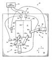
- the Figure illustrates positioning apparatus 10 generally comprising platform 12, first translating means 14 and second translating means 16, and preferably the positioning apparatus further comprises control means generally referenced at 20. More specifically, the first translating means includes first and second links 22 and 24 and linear actuator 26, the second translating means includes link 30 and linear actuator 32, and the control means includes sensors 34 and 36 and processors 40 and 42. With the embodiment of the invention shown in the Figure, the first translating means further includes link controller 44, and the control means further includes host processor 46, sensor 50 and processor 52.
- Platform 12 is provided to hold a workpiece or other object, and the platform is supported for movement in two orthogonal directions, represented in the Figure by the x and y axes and referred to herein as the x and y directions respectively.
- Platform 12 may have any suitable shape and size, although commonly it has a flat, rectangular or square shape, and the platform may be provided with any suitable means (not shown) to hold a workpiece securely on the platform in a fixed position relative thereto.
- the platform may be supported in any acceptable manner; and, for example, the platform may be positioned over a larger planar support surface 54 and supported by an air bearing or by slide bearings for movement over that surface.
- First translating means 14 is connected to platform 12 to move the platform in a first direction, such as the x direction; and second translating means 16 is connected to the platform to move the platform in a second direction orthogonal to the first direction, such as the y direction.
- first and second links 22 and 24 are each pivotally connected to the platform at 22a and 24a respectively, and pivotally connected to linear actuator 26 at 22b and 24b respectively; and link 30 is pivotally connected to the platform at 30a, and to linear actuator 32 at 30b.
- Actuator 26 may be operated to move links 22 and 24 in the x-direction, upward and downward as viewed in the Figure, thereby to move the platform likewise in the x direction.
- actuator 32 may be operated to move link 30, and thereby to move the platform, in the y-direction, leftward and rightward as viewed in the Figure.
- link 30 pivots about the pivot points 30a and 30b; and, if pivot point 30b remains at a fixed location, link 30 causes the platform to also move in the y direction.
- links 22 and 24 pivot about connections 22b and 24b respectively; and if connections 22b and 24b remain at fixed locations, links 22 and 24 cause the platform to move in the x direction.
- links 22 and 24, moveable platform 12 and linear actuator 26 form a pivotal parallelogram structure that maintains the orientation of the platform substantially constant during movement of the platform.
- the orientation of the platform can be considered as the angle formed between an axis fixed on the platform, such as the central longitudinal axis 12a of the platform, and another axis, such as the x-axis shown in the Figure, that remains fixed relative to the environment in which the platform is located. These two axes are parallel to each other as shown in the Figure; and the parallelogram structure formed by links 22 and 24, platform 12 and linear actuator 26 maintains these axes substantially parallel during movement of the platform.
- linear actuator 26 comprises moveable member 56, electric motor 60, motor controller 62, and connecting member 64; and actuator 32 comprises moveable member 66, electric motor 70 and motor controller 72.
- Moveable member 56 is supported for linear movement in the x-direction, and this moveable member is connected to links 22 and 24, via connecting member 64, to move those links along the x direction.
- Motor 60 is connected to moveable member 56 to move this member upward and downward as viewed in the Figure, and controller 62 is connected to motor 60 to control that motor so as to move the moveable member 56 selectively in response to signals transmitted to that controller.
- Moveable member 66 is supported for linear movement in the y-direction, and this moveable member is connected to link 30 to move that link along the y direction.
- Motor 70 is connected to moveable member 66 to move that member to the left and right as viewed in the Figure; and, in turn, controller 72 is connected to motor 70 to control that motor so as to move the moveable member 66 selectively in response to signals transmitted to the controller.
- each of the motors 60 and 70 comprises a servo motor having an output shaft
- each of the controllers 62 and 72 actuates the associated motor to rotate its output shaft either clockwise or counterclockwise in response to signals transmitted to the controller from control means 20.
- linear actuators may include hydraulic or pneumatic cylinders, and a controller to extend or retract the rods of the cylinders in response to signals transmitted to those controllers.
- Control means 20 is connected to first and second translating means 14 and 16 to control those translating means to move platform 12 through a series of positions; and preferably, the control means controls the translating means not only to do this, but also to move the platform on a predetermined path as the platform moves through that series of positions. To do this, the control means monitors the location of the platform as the platform moves from one position to another; and if the platform is not in the location at which it should be, the control means generates correction signals and transmits those correction signals to the first and second translating means, specifically controllers 62 and 72 thereof, to operate those translating means to move the platform toward or to the location in which it should be.
- sensors 34 and 36 sense the actual position of the platform and transmit to processors 40 and 42 signals representing that actual position.
- processors 40 and 42 compare the actual position of the platform to the desired position thereof at that time; and if these two positions are different, the processors generate and transmit control signals to the linear actuators 26 and 32 to operate those actuators to move the platform toward or into the desired position.
- sensor 36 senses the actual position of the left lateral edge 12b of the platform, and the sensor transmits to processor 42 a signal indicating that actual position.
- Processor 42 determines the desired position of the left lateral edge of the platform at this point in time. If the actual sensed position of edge 12b is to the left of the desired position, processor 42 generates and transmits to motor controller 72 a signal causing that controller to actuate motor 70 to pull link 30 to the right, thereby to pull the platform to the right.
- processor 42 generates and transmits to motor controller 72 a signal causing that controller to actuate motor 70 to push link 30 to the left, thereby to push the platform to the left.
- sensor 34 senses the actual position of the top lateral edge 12c of the platform, and the sensor transmits to processor 40 a signal indicating the actual position of edge 12c.
- Processor 40 determines the desired position of the top lateral edge of the platform at these points in time. On the one hand, if the actual sensed position of edge 12c is above the desired position, processor 40 generates and transmits to linear actuator 26, specifically controller 62, a signal causing that actuator to pull links 22 and 24 downward and thus to pull the platform downward. On the other hand, if the actual sensed position of edge 12c is below the desired position, processor 40 generates and transmits to linear actuator 26, specifically controller 62, a signal causing that actuator to push links 22 and 24 upward to push the platform upward.
- each of the processors 40 and 42 includes means to determine the desired coordinate data--specifically, the desired x coordinate of the top lateral edge 12c and the desired y coordinate of the left lateral edge 12b, respectively, of the platform--while the platform is moving.
- the processors may be programmed to determine the desired coordinate values according to given equations, or the processors may be provided with look-up tables to determine the desired coordinate values at various points during a given period of time.
- Host computer 46 is used to transmit to processors 40 and 42 any data or programs needed to determine the desired coordinate values.
- each processor includes a clock means that generates timing signals to enable the processor to keep track of time during movement of the platform. Alternatively, these timing signals may be transmitted to the processors from another device, such as the host computer.
- Sensors 34 and 36 may comprise any suitable position sensing devices.
- each of the sensors is or includes an interferometer, and the sensors are rigidly secured on support surface 54.
- Interferometers are available that can sense the position of an object with an accuracy of less than two nanometers, and such devices may be used in this invention.
- processors 40 and 42 may be any suitable processing devices.
- Sensor-processing units are commercially available that may be used as sensor 34 and processor 40, and as sensor 36 and processor 42, and suitable sensor-processing units include Hewlitt Packard's 5527 System, and Zygo Corporation's Axion 2-20.
- link 22 of first translating means 14 has an adjustable length
- apparatus 10 comprises means, including controller 44, sensor 50 and processor 52, to detect yaw in the movement of platform 12 and, upon sensing such yaw, to adjust the length of link 22 to return the platform to its desired orientation.
- link 22 comprises first and second sections 22c and d, each of which has a substantially constant length, and third section 22e, which has an adjustable length.
- One end of link section 22c is pivotally mounted on linear actuator 26, and the other end of this link section is secured to a first end of third section 22e.
- a second end of section 22e is secured to one end of link section 22d, and the other end of this latter link section is pivotally mounted on platform 12.
- Mid section 22e comprises an actuator such as a piezo transducer, the length of which is a function of the voltage difference applied across the transducer.
- Controller 44 is connected to link 22 to adjust the length thereof; and with the embodiment of the invention shown in the Figure, this is done by applying a variable voltage difference across piezo section 22e.
- the variable voltage is supplied to actuator 22e by controller 44 in response to signals generated by sensor 50 and processor 52.
- link 22 may be or include an extensible hydraulic or pneumatic cylinder
- controller 44 may be a hydraulic or pneumatic control valve used to control the extensible cylinder in response to the signal or signals transmitted to the control valve from processor 52.
- Link sections 22c and d, as well as links 24 and 30 and connecting member 64, may be made of any suitable material, such as aluminum or a rigid plastic, and the links may be connected in place in any acceptable manner.
- Sensor 50 and processor 52 operate in a manner very similar to sensors 34 and 36 and processors 40 and 42 to detect any deviation of platform 12 from a desired orientation, and if such a deviation is detected, to generate and to transmit to controller 44 a signal to operate that actuator to adjust the length of link 22 to return the platform to the desired orientation.
- sensor 50 also preferably is an interferometer rigidly secured on platform 54; and at each of a multitude of times during movement of the platform, sensor 50, senses the actual position of the top lateral edge 12c of the platform and transmits to processor 52 a signal indicating that actual position.
- Processor 52 determines the desired position of the top lateral edge of the platform at these points in time. If the actual sensed position of edge 12c is above the desired position, processor 52 generates and transmits to controller 44 a signal causing actuator 22e to retract link 22 to thereby pivot the top edge of the platform counterclockwise. However, if the actual sensed position of edge 12c is below the desired position, processor 52 generates and transmits to controller 44 a signal causing actuator 22e to extend link 22, thereby to pivot the top edge of the platform clockwise.
- Processor 52 is provided with means to determine the desired coordinate value, specifically the x-coordinate of top edge 12c of platform 12, during movement of the platform.
- Processor 52 may be programmed to determine the desired coordinate value according to a given equation, or the processor may be provided with a look-up table to determine the desired coordinate values at various points during a given period of time, and host computer 46 may be used to transmit to processor 52 any data or programs needed to determine the desired coordinate values.
- the processor may be provided with clock means that generates timing signals to enable the processor to keep track of time during movement of the platform, or these timing signals may be transmitted to the processor from another device such as the host computer.
Abstract
Description
- This invention generally relates to positioning mechanisms; and more specifically, to a mechanism for moving a platform in two orthogonal directions with a high degree of precision.
- Some industrial applications require that a workpiece be moved along two orthogonal directions with a very high degree of precision. For example, in the fabrication of integrated circuits, a wafer may be moved through a series of different positions, at each of which a multitude of operations are performed on the wafer. It is important that each operation be performed on a specific, often extremely small, area of the wafer; and to ensure that this is done, the wafer must be located precisely in each of its series of positions. In addition, operations may be performed on the wafer as it is being moved, for instance lithographic exposure, to score a line on the wafer or to deposit or remove material over a predetermined, often very narrow path or line on the wafer. To accomplish this, it is important that the wafer itself be moved with a very high degree of accuracy along a predetermined path.
- Various prior art devices are known to move a workpiece with a high degree of precision. Typically, these prior art devices employ complicated mechanical systems involving a large number of machine components, bearings, guideways and lead screws to move the workpiece as desired. These complicated mechanical systems are comparatively expensive and, moreover, as the mechanical elements of the systems wear with use, the precision of the systems decrease.
- An object of this invention is to improve two-dimensional positioning apparatus.
- Another object of the present invention is to provide a two-dimensional positioning apparatus that may be used to move a workpiece precisely through a predetermined pattern, without requiring a complex mechanical system.
- A further object of this invention is to use highly precise position sensors, rather than complicated mechanical systems, to move a workpiece precisely through a predetermined pattern.
- Still another object of the present invention is to provide a parallelogram structure, which is used to help maintain the orientation of a platform constant as the platform moves, with a link having an adjustable length, and to adjust the length of that link as the platform moves to further help maintain the orientation of the platform constant.
- These objects are solved basically by the solution given in the characterizing part of the independent claim 1.
- Further advantageous embodiments of the present invention are laid down in the subclaims.
- These and other objects are attained with a two-dimensional positioning mechanism, comprising a moveable platform, first translating means connected to the platform to move the platform in a first direction, and second translating means connected to the platform to move the platform in a second direction orthogonal to the first direction. The first translating means includes first and second links, each of which is pivotally connected to the platform, and a first linear actuator pivotally connected to the first and second links to move those links in the first direction. The first and second links, the moveable platform and the linear actuator form a pivotal parallelogram structure to maintain the orientation of the platform substantially constant during movement thereof.
- Preferably, the positioning mechanism further includes control means connected to the first and second translating means to control those translating means to move the platform from a first position to a second position. This control means preferably also controls the translating means to move the platform on a predetermined path as the platform moves from one position to the next. To do this, the control means employs first and second processor-sensor units to monitor the location of the platform, specifically first and second lateral edges thereof, as the platform moves. If, during this movement, the platform is not in the location at which it should be, the control means generates correction signals and transmits those signals to the first and second translating means to operate those translating means to move the platform to the location in which it should be.
- In addition, even with the above-mentioned parallelogram structure, the orientation of the platform may tend to change slightly, or yaw, during movement of the platform. To compensate for, or to prevent, this yaw, preferably one of the links of the first translating means has an adjustable length, and the positioning mechanism further includes means to sense yaw in movement of the platform, and upon sensing such yaw, to adjust the length of this adjustable link to return the platform to its desired orientation.
- Further benefits and advantages of the invention will become apparent from a consideration of the following detailed description given with reference to the accompanying drawing, which specifies and shows preferred embodiments of the invention.
- The invention will be shown in more detail in the following description in accordance with the sole Figure 1 in the drawing generally shows a positioning apparatus to the present invention.
- The Figure illustrates
positioning apparatus 10 generally comprisingplatform 12, first translating means 14 and second translating means 16, and preferably the positioning apparatus further comprises control means generally referenced at 20. More specifically, the first translating means includes first andsecond links linear actuator 26, the second translating means includeslink 30 andlinear actuator 32, and the control means includessensors processors link controller 44, and the control means further includeshost processor 46,sensor 50 andprocessor 52. -
Platform 12 is provided to hold a workpiece or other object, and the platform is supported for movement in two orthogonal directions, represented in the Figure by the x and y axes and referred to herein as the x and y directions respectively.Platform 12 may have any suitable shape and size, although commonly it has a flat, rectangular or square shape, and the platform may be provided with any suitable means (not shown) to hold a workpiece securely on the platform in a fixed position relative thereto. Also, the platform may be supported in any acceptable manner; and, for example, the platform may be positioned over a largerplanar support surface 54 and supported by an air bearing or by slide bearings for movement over that surface. -
First translating means 14 is connected toplatform 12 to move the platform in a first direction, such as the x direction; and second translating means 16 is connected to the platform to move the platform in a second direction orthogonal to the first direction, such as the y direction. More specifically, first andsecond links linear actuator 26 at 22b and 24b respectively; andlink 30 is pivotally connected to the platform at 30a, and tolinear actuator 32 at 30b.Actuator 26 may be operated to movelinks actuator 32 may be operated to movelink 30, and thereby to move the platform, in the y-direction, leftward and rightward as viewed in the Figure. Aslinks pivot points pivot point 30b remains at a fixed location,link 30 causes the platform to also move in the y direction. Similarly, aslink 30 is moved to move the platform in the y direction,links connections connections links - With the above-described arrangement,
links moveable platform 12 andlinear actuator 26 form a pivotal parallelogram structure that maintains the orientation of the platform substantially constant during movement of the platform. To elaborate, the orientation of the platform can be considered as the angle formed between an axis fixed on the platform, such as the centrallongitudinal axis 12a of the platform, and another axis, such as the x-axis shown in the Figure, that remains fixed relative to the environment in which the platform is located. These two axes are parallel to each other as shown in the Figure; and the parallelogram structure formed bylinks platform 12 andlinear actuator 26 maintains these axes substantially parallel during movement of the platform. - Linear actuators are available that can move an object to a desired position with an accuracy of 10 nanometers, and such actuators may be used in this invention. In the embodiment of the invention illustrated in the Figure,
linear actuator 26 comprisesmoveable member 56,electric motor 60,motor controller 62, and connectingmember 64; andactuator 32 comprisesmoveable member 66,electric motor 70 andmotor controller 72.Moveable member 56 is supported for linear movement in the x-direction, and this moveable member is connected tolinks member 64, to move those links along the x direction.Motor 60 is connected tomoveable member 56 to move this member upward and downward as viewed in the Figure, andcontroller 62 is connected tomotor 60 to control that motor so as to move themoveable member 56 selectively in response to signals transmitted to that controller. -
Moveable member 66 is supported for linear movement in the y-direction, and this moveable member is connected tolink 30 to move that link along the y direction.Motor 70 is connected tomoveable member 66 to move that member to the left and right as viewed in the Figure; and, in turn,controller 72 is connected tomotor 70 to control that motor so as to move themoveable member 66 selectively in response to signals transmitted to the controller. - Moreover, preferably each of the
motors controllers control means 20. - Numerous other specific types of linear actuators may be employed in
apparatus 10. For example, these actuators may include hydraulic or pneumatic cylinders, and a controller to extend or retract the rods of the cylinders in response to signals transmitted to those controllers. - Control means 20 is connected to first and second translating means 14 and 16 to control those translating means to move
platform 12 through a series of positions; and preferably, the control means controls the translating means not only to do this, but also to move the platform on a predetermined path as the platform moves through that series of positions. To do this, the control means monitors the location of the platform as the platform moves from one position to another; and if the platform is not in the location at which it should be, the control means generates correction signals and transmits those correction signals to the first and second translating means, specificallycontrollers - More specifically, at each of a multitude of times during movement of the platform,
sensors processors Processors linear actuators - Even more specifically, at each of a multitude of points in time, preferably at regular intervals, during this movement of the platform,
sensor 36 senses the actual position of the leftlateral edge 12b of the platform, and the sensor transmits to processor 42 a signal indicating that actual position.Processor 42 determines the desired position of the left lateral edge of the platform at this point in time. If the actual sensed position ofedge 12b is to the left of the desired position,processor 42 generates and transmits to motor controller 72 a signal causing that controller to actuatemotor 70 to pulllink 30 to the right, thereby to pull the platform to the right. However, if the actual sensed position ofedge 12b is to the right of the desired position,processor 42 generates and transmits to motor controller 72 a signal causing that controller to actuatemotor 70 to pushlink 30 to the left, thereby to push the platform to the left. - Similarly, at each of a multitude of points in time, also preferably at regular intervals, during movement of the platform,
sensor 34 senses the actual position of the toplateral edge 12c of the platform, and the sensor transmits to processor 40 a signal indicating the actual position ofedge 12c.Processor 40 determines the desired position of the top lateral edge of the platform at these points in time. On the one hand, if the actual sensed position ofedge 12c is above the desired position,processor 40 generates and transmits tolinear actuator 26, specifically controller 62, a signal causing that actuator to pulllinks edge 12c is below the desired position,processor 40 generates and transmits tolinear actuator 26, specifically controller 62, a signal causing that actuator to pushlinks - While
platform 12 moves from one position to another, the desired location of the platform may, and typically does, change in both the x and y directions. Hence, preferably, each of theprocessors lateral edge 12c and the desired y coordinate of the leftlateral edge 12b, respectively, of the platform--while the platform is moving. For example, the processors may be programmed to determine the desired coordinate values according to given equations, or the processors may be provided with look-up tables to determine the desired coordinate values at various points during a given period of time.Host computer 46 is used to transmit toprocessors -
Sensors support surface 54. Interferometers are available that can sense the position of an object with an accuracy of less than two nanometers, and such devices may be used in this invention. Likewise,processors sensor 34 andprocessor 40, and assensor 36 andprocessor 42, and suitable sensor-processing units include Hewlitt Packard's 5527 System, and Zygo Corporation's Axion 2-20. - As previously mentioned, the parallelogram structure formed by
platform 12,links linear actuator 26 ensure that the orientation of the platform remains substantially constant as the platform moves. However, if the distance between the center of connectingpoints points means 14 has an adjustable length, andapparatus 10 comprises means, includingcontroller 44,sensor 50 andprocessor 52, to detect yaw in the movement ofplatform 12 and, upon sensing such yaw, to adjust the length oflink 22 to return the platform to its desired orientation. - More particularly, as shown in the Figure, link 22 comprises first and
second sections 22c and d, each of which has a substantially constant length, andthird section 22e, which has an adjustable length. One end oflink section 22c is pivotally mounted onlinear actuator 26, and the other end of this link section is secured to a first end ofthird section 22e. A second end ofsection 22e is secured to one end oflink section 22d, and the other end of this latter link section is pivotally mounted onplatform 12.Mid section 22e comprises an actuator such as a piezo transducer, the length of which is a function of the voltage difference applied across the transducer. -
Controller 44 is connected to link 22 to adjust the length thereof; and with the embodiment of the invention shown in the Figure, this is done by applying a variable voltage difference acrosspiezo section 22e. The variable voltage is supplied toactuator 22e bycontroller 44 in response to signals generated bysensor 50 andprocessor 52. - Other types of extensible links may be used in the practice of the present invention, and other types of controllers may be used to extend or adjust the length of that link. For example, link 22 may be or include an extensible hydraulic or pneumatic cylinder, and
controller 44 may be a hydraulic or pneumatic control valve used to control the extensible cylinder in response to the signal or signals transmitted to the control valve fromprocessor 52. -
Link sections 22c and d, as well aslinks member 64, may be made of any suitable material, such as aluminum or a rigid plastic, and the links may be connected in place in any acceptable manner. -
Sensor 50 andprocessor 52 operate in a manner very similar tosensors processors platform 12 from a desired orientation, and if such a deviation is detected, to generate and to transmit to controller 44 a signal to operate that actuator to adjust the length oflink 22 to return the platform to the desired orientation. - In particular,
sensor 50 also preferably is an interferometer rigidly secured onplatform 54; and at each of a multitude of times during movement of the platform,sensor 50, senses the actual position of the toplateral edge 12c of the platform and transmits to processor 52 a signal indicating that actual position. -
Processor 52 determines the desired position of the top lateral edge of the platform at these points in time. If the actual sensed position ofedge 12c is above the desired position,processor 52 generates and transmits to controller 44 asignal causing actuator 22e to retractlink 22 to thereby pivot the top edge of the platform counterclockwise. However, if the actual sensed position ofedge 12c is below the desired position,processor 52 generates and transmits to controller 44 asignal causing actuator 22e to extendlink 22, thereby to pivot the top edge of the platform clockwise. -
Processor 52 is provided with means to determine the desired coordinate value, specifically the x-coordinate oftop edge 12c ofplatform 12, during movement of the platform.Processor 52 may be programmed to determine the desired coordinate value according to a given equation, or the processor may be provided with a look-up table to determine the desired coordinate values at various points during a given period of time, andhost computer 46 may be used to transmit toprocessor 52 any data or programs needed to determine the desired coordinate values. The processor may be provided with clock means that generates timing signals to enable the processor to keep track of time during movement of the platform, or these timing signals may be transmitted to the processor from another device such as the host computer.
Claims (15)
- A two-dimensional positioning mechanism, comprising:
a moveable platform (12) having a given orientation;
first translating means (14) connected to the platform to move the platform in a first direction, and includingi) first (22) and second (24) links, each link being pivotally connected to the platform, andii) a first linear actuator (26) pivotally connected to the first (22) and second (24) links, to move the links in said first direction; andsecond translating means (16) connected to the platform to move the platform in a second direction orthogonal to the first direction;
wherein the first (22) and second (24) links, the moveable platform (12) and the first linear actuator (26) form a pivotal parallelogram structure to maintain the orientation of the platform substantially constant during movement thereof. - A positioning mechanism according to claim 1, further comprising control means (20) connected to the first (22) and second (24) translating means to control said translating means (12) to move the platform especially on predetermined path from a first position to a second position.
- A positioning mechanism according to claim 1 or 2, wherein:
the first link (22) has an adjustable length, and includes a link actuator (22e) connected to the first link (22) to adjust the length of the first link; and
the control means (44) includes yaw control means to sense deviation of the platform from the given orientation, and connected to the link actuator (22e) to adjust the length of the first link (22) to return the platform to the given orientation. - A positioning mechanism according to claim 1, 2 or 3, wherein the second translating means (16) includes:
a third link (30) pivotally connected to the platform (12); and
a second linear actuator (32) pivotally connected to the third link to move the third link in the second direction. - A positioning mechanism according to claim 1, 2, 3 or 4, wherein:
the first linear actuator (26) includesi) a first electric motor,ii) means connecting the first electric motor to the first and second links, andiii) a first controller (62) connected to the first electric motor to control operation thereof; andthe second linear actuator (32) includesi) a second electric motor,ii) means connecting the second electric motor to the third link, andiii) a second controller (72) connected to the second electric motor to control operation thereof. - A positioning mechanism according to claim 2, wherein the control means (20) includes:
first means (34) to sense the position of the platform (12) in the first direction, to generate a first correction signal if the position of the platform in the first direction is different from a desired position, and to transmit the first correction signal to the first controller (62) to actuate the first electric motor to move the first and second links and the platform in the first direction to said desired position; and
second means (36) to sense the position of the platform (12) in the second direction, to generate a second correction signal if the position of the platform in the second direction is different from a desired position, and to transmit the second correction signal to the second controller (72) to actuate the second electric motor to move the third link and the platform to said desired position in the second direction. - A positioning mechanism according to claim 6, wherein:
the first means includesi) a first sensor (34) to sense the position of the platform in the first direction, andii) a first processor (40) to determine the desired position of the platform (12) in the first direction; andthe second means includesi) a second sensor (36) to sense the position of the platform in the second direction, andii) a second processor (42) to determine the desired position of the platform in the second position. - A positioning mechanism according to claim 6 or 7, wherein:
the platform (12) has first and second lateral sides;
the first sensor (34) senses the position of the first lateral side of the platform (12); and
the second sensor (36) senses the position of the second lateral side of the platform (12). - A positioning mechanism according to claim 6, 7 or 8, wherein the desired positions of the platform (12) in the first and second directions vary over a given period of time, and wherein:
the first processor (40) includes means to determine the desired position of the platform in the first direction during said period; and
the second processor (42) includes means to determine the desired position of the platform (12) in the second direction during said period. - A positioning mechanism according to claim 1, wherein:
the first link (22) has an adjustable length; and
the first translating means (14) further includes a link controller (44) connected to the first link to adjust the length thereof. - A positioning mechanism according to claim 1, further comprising yaw control means to sense deviation of the platform (12) from the given orientation, and connected to the link controller to operate the link controller to adjust the length of the first link to return the platform to the given orientation.
- A positioning mechanism according to claim 1 or 11, herein the yaw control means includes:
a yaw sensor (50) to sense the position of the platform in a given direction especially of the first lateral side of the platform (12); and
a processor (52) to determine the desired position of the platform in said given direction. - A positioning mechanism according to claim 1, 11 or 12, wherein the desired position of the platform especially of the first lateral side of the platform in the given direction varies over a given period of time, and the processor (52) includes means to determine the desired position of the platform especially of the first lateral side of the platform in the given direction during said period.
- A positioning mechanism according to claim 1, 11, 12 or 13, wherein:
the platform has a first lateral side; and
the yaw control means senses the position of said first lateral side and generates and transmits to the link controller a yaw correction signal when the position of the first lateral side of the platform is different from a desired position. - A positioning mechanism according to claim 1 or 2, wherein:
the first link includesi) a first section pivotally connected to the platform,ii) a second section pivotally connected to the first linear actuator, andiii) an adjustable length piezo section connected to and extending between the first and second sections of the link; andthe link controller is electrically connected to the first link to apply a variable voltage potential across the piezo section to vary the length thereof.
Applications Claiming Priority (2)
| Application Number | Priority Date | Filing Date | Title |
|---|---|---|---|
| US07/466,089 US5059090A (en) | 1990-01-16 | 1990-01-16 | Two-dimensional positioning apparatus |
| US466089 | 1990-01-16 |
Publications (2)
| Publication Number | Publication Date |
|---|---|
| EP0437741A2 true EP0437741A2 (en) | 1991-07-24 |
| EP0437741A3 EP0437741A3 (en) | 1991-09-18 |
Family
ID=23850416
Family Applications (1)
| Application Number | Title | Priority Date | Filing Date |
|---|---|---|---|
| EP19900124053 Withdrawn EP0437741A3 (en) | 1990-01-16 | 1990-12-13 | A two-dimensional positioning apparatus |
Country Status (3)
| Country | Link |
|---|---|
| US (1) | US5059090A (en) |
| EP (1) | EP0437741A3 (en) |
| JP (1) | JPH03218046A (en) |
Cited By (6)
| Publication number | Priority date | Publication date | Assignee | Title |
|---|---|---|---|---|
| WO1997008595A1 (en) * | 1995-08-29 | 1997-03-06 | Hesse Gmbh | Device for compensating guide tolerance in multi-axis positioners |
| EP1544911A2 (en) * | 2003-12-17 | 2005-06-22 | Erich Dipl.-Ing. Thallner | Adjusting device |
| WO2008085510A1 (en) * | 2007-01-05 | 2008-07-17 | Active Precision, Inc. | High-speed substrate manipulator |
| WO2012089852A1 (en) * | 2010-12-30 | 2012-07-05 | Ideko, S. Coop. | Machine tool guide bench |
| US8353199B1 (en) | 2009-04-17 | 2013-01-15 | Arrowhead Center, Inc. | Multi-degree-of-freedom test stand for unmanned air vehicles |
| US9228917B1 (en) | 2009-04-17 | 2016-01-05 | Arrowhead Center, Inc. | Six degrees of freedom free-motion test apparatus |
Families Citing this family (16)
| Publication number | Priority date | Publication date | Assignee | Title |
|---|---|---|---|---|
| US5170678A (en) * | 1990-04-30 | 1992-12-15 | Walter W. Wawrzyniak | Index table assembly |
| US5509777A (en) * | 1993-03-25 | 1996-04-23 | Leland D. Blatt | Mechanical side shift and tip apparatus |
| US6989647B1 (en) * | 1994-04-01 | 2006-01-24 | Nikon Corporation | Positioning device having dynamically isolated frame, and lithographic device provided with such a positioning device |
| US5528118A (en) * | 1994-04-01 | 1996-06-18 | Nikon Precision, Inc. | Guideless stage with isolated reaction stage |
| US7365513B1 (en) | 1994-04-01 | 2008-04-29 | Nikon Corporation | Positioning device having dynamically isolated frame, and lithographic device provided with such a positioning device |
| US5874820A (en) * | 1995-04-04 | 1999-02-23 | Nikon Corporation | Window frame-guided stage mechanism |
| US6246204B1 (en) | 1994-06-27 | 2001-06-12 | Nikon Corporation | Electromagnetic alignment and scanning apparatus |
| US5623853A (en) * | 1994-10-19 | 1997-04-29 | Nikon Precision Inc. | Precision motion stage with single guide beam and follower stage |
| US6008500A (en) * | 1995-04-04 | 1999-12-28 | Nikon Corporation | Exposure apparatus having dynamically isolated reaction frame |
| TW318255B (en) | 1995-05-30 | 1997-10-21 | Philips Electronics Nv | |
| US5760564A (en) * | 1995-06-27 | 1998-06-02 | Nikon Precision Inc. | Dual guide beam stage mechanism with yaw control |
| US5906468A (en) * | 1995-09-22 | 1999-05-25 | Bell & Howell Postal Systems Inc. | Pivotal tray unloading apparatus |
| US5769574A (en) * | 1996-03-29 | 1998-06-23 | Feinsod; Stephen S. | Method and apparatus for precision boring of pocket-holes |
| JP5028659B2 (en) * | 2007-08-24 | 2012-09-19 | 秋田県 | Positioning mechanism |
| US8601619B2 (en) * | 2009-03-27 | 2013-12-10 | Astir Technologies, Llc | Body transfer system with yaw control |
| TWI472397B (en) * | 2012-02-10 | 2015-02-11 | 中原大學 | Two - legged mobile platform structure |
Citations (6)
| Publication number | Priority date | Publication date | Assignee | Title |
|---|---|---|---|---|
| FR2190187A5 (en) * | 1972-06-22 | 1974-01-25 | Onera (Off Nat Aerospatiale) | |
| JPS5481576A (en) * | 1977-12-09 | 1979-06-29 | Fujitsu Ltd | Device to determine the position of a slide table |
| GB2067932A (en) * | 1980-01-25 | 1981-08-05 | Charmilles Sa Ateliers | Work support table |
| US4610442A (en) * | 1982-10-19 | 1986-09-09 | Matsushita Electric Industrial Co, Ltd. | Positioning table |
| JPS61270044A (en) * | 1985-05-24 | 1986-11-29 | Toshiba Corp | Three axes movable stage |
| EP0314839A1 (en) * | 1986-01-20 | 1989-05-10 | De Haan Mechatronics B.V. | Positioning apparatus |
Family Cites Families (7)
| Publication number | Priority date | Publication date | Assignee | Title |
|---|---|---|---|---|
| US893068A (en) * | 1906-08-15 | 1908-07-14 | Linen Thread Company | Mechanical movement. |
| US2244215A (en) * | 1938-02-19 | 1941-06-03 | Participations Eau Soc Et | Free piston machine |
| US2521895A (en) * | 1945-08-23 | 1950-09-12 | Ferguson Harry Inc | Earth boring attachment for tractors |
| US3376755A (en) * | 1966-08-24 | 1968-04-09 | Collins Radio Co | Mechanical movement |
| US3948467A (en) * | 1974-01-19 | 1976-04-06 | Dornier Gmbh | Device for position stabilization |
| US4400985A (en) * | 1981-04-22 | 1983-08-30 | Bond Irvin D | Straight line link mechanism |
| DD229387A1 (en) * | 1984-12-07 | 1985-11-06 | Vta Leipzig Paul Froehlich Veb | LIFTING DEVICE, ESPECIALLY FOR FORKLIFTS |
-
1990
- 1990-01-16 US US07/466,089 patent/US5059090A/en not_active Expired - Fee Related
- 1990-11-28 JP JP2323430A patent/JPH03218046A/en active Granted
- 1990-12-13 EP EP19900124053 patent/EP0437741A3/en not_active Withdrawn
Patent Citations (6)
| Publication number | Priority date | Publication date | Assignee | Title |
|---|---|---|---|---|
| FR2190187A5 (en) * | 1972-06-22 | 1974-01-25 | Onera (Off Nat Aerospatiale) | |
| JPS5481576A (en) * | 1977-12-09 | 1979-06-29 | Fujitsu Ltd | Device to determine the position of a slide table |
| GB2067932A (en) * | 1980-01-25 | 1981-08-05 | Charmilles Sa Ateliers | Work support table |
| US4610442A (en) * | 1982-10-19 | 1986-09-09 | Matsushita Electric Industrial Co, Ltd. | Positioning table |
| JPS61270044A (en) * | 1985-05-24 | 1986-11-29 | Toshiba Corp | Three axes movable stage |
| EP0314839A1 (en) * | 1986-01-20 | 1989-05-10 | De Haan Mechatronics B.V. | Positioning apparatus |
Non-Patent Citations (1)
| Title |
|---|
| IBM TECHNICAL DISCLOSURE BULLETIN, vol. 30, no. 5, October 1987, pages 299-300, Armonk, New York, US; "High-speed micro-positioner" * |
Cited By (9)
| Publication number | Priority date | Publication date | Assignee | Title |
|---|---|---|---|---|
| WO1997008595A1 (en) * | 1995-08-29 | 1997-03-06 | Hesse Gmbh | Device for compensating guide tolerance in multi-axis positioners |
| EP1544911A2 (en) * | 2003-12-17 | 2005-06-22 | Erich Dipl.-Ing. Thallner | Adjusting device |
| EP1544911A3 (en) * | 2003-12-17 | 2005-11-23 | Erich Dipl.-Ing. Thallner | Adjusting device |
| US7246445B2 (en) | 2003-12-17 | 2007-07-24 | Erich Thallner | Alignment device |
| WO2008085510A1 (en) * | 2007-01-05 | 2008-07-17 | Active Precision, Inc. | High-speed substrate manipulator |
| US7898204B2 (en) | 2007-01-05 | 2011-03-01 | Active Precision, Inc. | High-speed substrate manipulator |
| US8353199B1 (en) | 2009-04-17 | 2013-01-15 | Arrowhead Center, Inc. | Multi-degree-of-freedom test stand for unmanned air vehicles |
| US9228917B1 (en) | 2009-04-17 | 2016-01-05 | Arrowhead Center, Inc. | Six degrees of freedom free-motion test apparatus |
| WO2012089852A1 (en) * | 2010-12-30 | 2012-07-05 | Ideko, S. Coop. | Machine tool guide bench |
Also Published As
| Publication number | Publication date |
|---|---|
| EP0437741A3 (en) | 1991-09-18 |
| JPH03218046A (en) | 1991-09-25 |
| US5059090A (en) | 1991-10-22 |
| JPH0574227B2 (en) | 1993-10-18 |
Similar Documents
| Publication | Publication Date | Title |
|---|---|---|
| US5059090A (en) | Two-dimensional positioning apparatus | |
| US6157157A (en) | Positioning system | |
| US5903125A (en) | Positioning system | |
| EP0327949B1 (en) | Alignment stage device | |
| JP2004006688A (en) | Compensation of load resistance of cable in high precision stage | |
| JPH1110575A (en) | Parallel link mechanism | |
| JPH02105543A (en) | Method and apparatus for correcting reproducible positioning error | |
| SE504378C2 (en) | Bending press system provided with a plate holding manipulator and a plate position detecting device | |
| KR20210125067A (en) | Through-beam automatic teaching | |
| JP2002263973A (en) | Machine tool | |
| US5243872A (en) | Robotic hand for controlling movement in multiple axes | |
| JP2003340661A (en) | Machining method, machining apparatus, and machining system equipped with the machining apparatus | |
| KR100392442B1 (en) | Stage apparatus | |
| EP0625739B1 (en) | Apparatus for movement of an object | |
| JP3275544B2 (en) | Stage equipment | |
| JPH05329786A (en) | Industrial robot device | |
| JPH03164811A (en) | Servo motor feed correcting method | |
| JP2758810B2 (en) | Shape measurement method | |
| JPH11151639A (en) | Inprocess measurement device | |
| JP2000322116A (en) | Servo controller and positioning device | |
| US11654562B2 (en) | Apparatus, robot control device, robot system, and method of setting robot coordinate system | |
| JP3497541B2 (en) | Bending machine | |
| JPH08278122A (en) | On-line plate thickness measuring method and device | |
| JP3852486B2 (en) | Stage drive controller | |
| JPH07219636A (en) | Stage device |
Legal Events
| Date | Code | Title | Description |
|---|---|---|---|
| PUAI | Public reference made under article 153(3) epc to a published international application that has entered the european phase |
Free format text: ORIGINAL CODE: 0009012 |
|
| AK | Designated contracting states |
Kind code of ref document: A2 Designated state(s): DE FR GB |
|
| PUAL | Search report despatched |
Free format text: ORIGINAL CODE: 0009013 |
|
| AK | Designated contracting states |
Kind code of ref document: A3 Designated state(s): DE FR GB |
|
| 17P | Request for examination filed |
Effective date: 19911112 |
|
| 17Q | First examination report despatched |
Effective date: 19920630 |
|
| STAA | Information on the status of an ep patent application or granted ep patent |
Free format text: STATUS: THE APPLICATION IS DEEMED TO BE WITHDRAWN |
|
| 18D | Application deemed to be withdrawn |
Effective date: 19930611 |