EP0438974A1 - Method for packaging sleeves or tubes in boxes, and machine for executing the method - Google Patents
Method for packaging sleeves or tubes in boxes, and machine for executing the method Download PDFInfo
- Publication number
- EP0438974A1 EP0438974A1 EP90810993A EP90810993A EP0438974A1 EP 0438974 A1 EP0438974 A1 EP 0438974A1 EP 90810993 A EP90810993 A EP 90810993A EP 90810993 A EP90810993 A EP 90810993A EP 0438974 A1 EP0438974 A1 EP 0438974A1
- Authority
- EP
- European Patent Office
- Prior art keywords
- tubes
- slide
- sleeves
- compensator
- carriage
- Prior art date
- Legal status (The legal status is an assumption and is not a legal conclusion. Google has not performed a legal analysis and makes no representation as to the accuracy of the status listed.)
- Granted
Links
Images


Classifications
-
- B—PERFORMING OPERATIONS; TRANSPORTING
- B65—CONVEYING; PACKING; STORING; HANDLING THIN OR FILAMENTARY MATERIAL
- B65B—MACHINES, APPARATUS OR DEVICES FOR, OR METHODS OF, PACKAGING ARTICLES OR MATERIALS; UNPACKING
- B65B19/00—Packaging rod-shaped or tubular articles susceptible to damage by abrasion or pressure, e.g. cigarettes, cigars, macaroni, spaghetti, drinking straws or welding electrodes
- B65B19/34—Packaging other rod-shaped articles, e.g. sausages, macaroni, spaghetti, drinking straws, welding electrodes
-
- B—PERFORMING OPERATIONS; TRANSPORTING
- B65—CONVEYING; PACKING; STORING; HANDLING THIN OR FILAMENTARY MATERIAL
- B65B—MACHINES, APPARATUS OR DEVICES FOR, OR METHODS OF, PACKAGING ARTICLES OR MATERIALS; UNPACKING
- B65B35/00—Supplying, feeding, arranging or orientating articles to be packaged
- B65B35/02—Supply magazines
- B65B35/04—Supply magazines with buffer storage devices
-
- B—PERFORMING OPERATIONS; TRANSPORTING
- B65—CONVEYING; PACKING; STORING; HANDLING THIN OR FILAMENTARY MATERIAL
- B65B—MACHINES, APPARATUS OR DEVICES FOR, OR METHODS OF, PACKAGING ARTICLES OR MATERIALS; UNPACKING
- B65B5/00—Packaging individual articles in containers or receptacles, e.g. bags, sacks, boxes, cartons, cans, jars
- B65B5/10—Filling containers or receptacles progressively or in stages by introducing successive articles, or layers of articles
- B65B5/106—Filling containers or receptacles progressively or in stages by introducing successive articles, or layers of articles by pushers
-
- B—PERFORMING OPERATIONS; TRANSPORTING
- B65—CONVEYING; PACKING; STORING; HANDLING THIN OR FILAMENTARY MATERIAL
- B65G—TRANSPORT OR STORAGE DEVICES, e.g. CONVEYORS FOR LOADING OR TIPPING, SHOP CONVEYOR SYSTEMS OR PNEUMATIC TUBE CONVEYORS
- B65G47/00—Article or material-handling devices associated with conveyors; Methods employing such devices
- B65G47/02—Devices for feeding articles or materials to conveyors
- B65G47/04—Devices for feeding articles or materials to conveyors for feeding articles
- B65G47/06—Devices for feeding articles or materials to conveyors for feeding articles from a single group of articles arranged in orderly pattern, e.g. workpieces in magazines
- B65G47/08—Devices for feeding articles or materials to conveyors for feeding articles from a single group of articles arranged in orderly pattern, e.g. workpieces in magazines spacing or grouping the articles during feeding
- B65G47/082—Devices for feeding articles or materials to conveyors for feeding articles from a single group of articles arranged in orderly pattern, e.g. workpieces in magazines spacing or grouping the articles during feeding grouping articles in rows
-
- B—PERFORMING OPERATIONS; TRANSPORTING
- B65—CONVEYING; PACKING; STORING; HANDLING THIN OR FILAMENTARY MATERIAL
- B65G—TRANSPORT OR STORAGE DEVICES, e.g. CONVEYORS FOR LOADING OR TIPPING, SHOP CONVEYOR SYSTEMS OR PNEUMATIC TUBE CONVEYORS
- B65G47/00—Article or material-handling devices associated with conveyors; Methods employing such devices
- B65G47/34—Devices for discharging articles or materials from conveyor
- B65G47/46—Devices for discharging articles or materials from conveyor and distributing, e.g. automatically, to desired points
- B65G47/51—Devices for discharging articles or materials from conveyor and distributing, e.g. automatically, to desired points according to unprogrammed signals, e.g. influenced by supply situation at destination
- B65G47/5104—Devices for discharging articles or materials from conveyor and distributing, e.g. automatically, to desired points according to unprogrammed signals, e.g. influenced by supply situation at destination for articles
- B65G47/5109—Devices for discharging articles or materials from conveyor and distributing, e.g. automatically, to desired points according to unprogrammed signals, e.g. influenced by supply situation at destination for articles first In - First Out systems: FIFO
- B65G47/5113—Devices for discharging articles or materials from conveyor and distributing, e.g. automatically, to desired points according to unprogrammed signals, e.g. influenced by supply situation at destination for articles first In - First Out systems: FIFO using endless conveyors
- B65G47/5118—Devices for discharging articles or materials from conveyor and distributing, e.g. automatically, to desired points according to unprogrammed signals, e.g. influenced by supply situation at destination for articles first In - First Out systems: FIFO using endless conveyors with variable accumulation capacity
- B65G47/5122—Devices for discharging articles or materials from conveyor and distributing, e.g. automatically, to desired points according to unprogrammed signals, e.g. influenced by supply situation at destination for articles first In - First Out systems: FIFO using endless conveyors with variable accumulation capacity by displacement of the conveyor-guiding means, e.g. of the loose pulley-type
-
- B—PERFORMING OPERATIONS; TRANSPORTING
- B65—CONVEYING; PACKING; STORING; HANDLING THIN OR FILAMENTARY MATERIAL
- B65G—TRANSPORT OR STORAGE DEVICES, e.g. CONVEYORS FOR LOADING OR TIPPING, SHOP CONVEYOR SYSTEMS OR PNEUMATIC TUBE CONVEYORS
- B65G2201/00—Indexing codes relating to handling devices, e.g. conveyors, characterised by the type of product or load being conveyed or handled
- B65G2201/02—Articles
- B65G2201/0235—Containers
- B65G2201/0244—Bottles
-
- B—PERFORMING OPERATIONS; TRANSPORTING
- B65—CONVEYING; PACKING; STORING; HANDLING THIN OR FILAMENTARY MATERIAL
- B65G—TRANSPORT OR STORAGE DEVICES, e.g. CONVEYORS FOR LOADING OR TIPPING, SHOP CONVEYOR SYSTEMS OR PNEUMATIC TUBE CONVEYORS
- B65G2207/00—Indexing codes relating to constructional details, configuration and additional features of a handling device, e.g. Conveyors
- B65G2207/14—Combination of conveyors
Definitions
- the tubes or sleeves arrive from a discharge drum on a slide or inclined plate, from which they arrive on a conveyor belt with dividing lamellae.
- This belt runs continuously until the desired number of tubes or tubes is in front of a push-off.
- the tape is held and a batch of Tubes or sleeves are pushed into an auxiliary form or directly into the box, the number of tubes being adapted to the mass of the box.
- the sleeves coming from the production line are discharged via a delivery drum onto an endless belt of trays lined up in series.
- the tubes in the bowls are tipped on a flat conveyor belt and held by means of brushes arranged above and pushed together until the correct number of tubes for a shift is reached, whereupon the tubes are pushed directly or indirectly into the box perpendicular to the direction of movement of the belt.
- the other variant can be used for any tube size. Only the height of the brush above the conveyor belt has to be adjusted to the diameter of the tubes or sleeves.
- the problem here is that the guidance of the tubes on the flat conveyor belt is unsafe. If a tube is top-heavy, it twists and can mess up the order of all subsequent tubes.
- Another disadvantage is seen in the fact that the rolls or sleeves transported on the flat belt rub against one another and thereby scratch themselves easily.
- the solution proved to be particularly disadvantageous in the case of tubes or sleeves made of plastic laminates, which can become charged when rubbed under the brush in such a way that they stick to one another or deform completely.
- the present invention relates to the conveyance of the tubes or sleeves from the compensator 3 to the box conveyor 10 and from here into the box 9.
- the box 9 is transported on a conveyor belt 12 into the box conveyor 10 and is lifted up accordingly, so that the tubes are layered into the Box 9 can be pushed, whereupon the box is lowered by the height of one layer and the next layer of tubes can be inserted. If the box 9 is completely filled, it is pushed aside and slides on the roller conveyor 13 to the shipping company.
- a funding is in the form of a Carriage 4 provided.
- the carriage 4 rolls on rails 5 which extend at least from the compensator 3 to the area in which the tubes are pushed into the box 9 provided by the carriage 4.
- This accomplishes the transverse slide 8 directed transversely to the direction of movement of the slide 4.
- the slide 4, which rolls on the rails 5, is moved by a stepper motor 6 via a spindle 7.
- the stepper motor could of course also move the slide 4 back and forth according to the control program via a toothed belt.
- the carriage 4 is moved step by step in a cycle that is faster than the cycle in which the tubes or sleeves continuously come from the production plant.
- the path of the slide per step corresponds to the division 45 of the sheet 44 (see FIG. 4). If the required number of tubes is deposited on the sheet 44, which is required to form a layer, the compensator 3 is stopped in the area of its delivery point 38 and the carriage 4 moves to the side so far that it is aligned with the box 9 and the Tubes or sleeves can be pushed down from sheet 44 by means of cross slide 8. Then the slide 4 on the rails 5 is again completely shifted to the right, so that the next delivery of a tube or sleeve from the compensator furthest left division 45 is filled and now again the carriage can be gradually shifted to the left.
- the direct insertion of the tubes into the box 9 is a particularly inexpensive option, but requires a good carton quality.
- the time to replace the box 9 may only be very short. This can be achieved by not pushing the tubes directly into the box, but only on an intermediate support that pushes all tubes together that correspond to a box filling into the box. During this time, the tubes are pushed onto an auxiliary intermediate carrier until the main intermediate carrier is free again, whereupon the tubes lying on the auxiliary intermediate carrier are released onto the main intermediate carrier.
- This system is already known from Swiss Patent No. 658,632 and is described in detail herein.
- the compensator is of great importance in this process.
- a compensator which is particularly preferred for this machine is therefore shown in FIG.
- the compensator essentially consists of two parallel, parallel, endless chains 30 between which gondolas 31 are created.
- the gondolas 31 serve to transport the sleeves or tubes. Only a few gondolas 31 are shown in the drawing, while in reality one gondola follows the other gondola in close proximity.
- the chains 30 running over deflection rollers 32 are moved by a drive roller 33.
- the loading point 37 In the figure on the far left is the loading point 37, at which the tubes or sleeves coming from the production system are released into the gondolas 31.
- the chain 30 must run continuously and synchronously with the conveyor belt of the production plant.
- the two loops 35 and 36 are guided over deflection rollers which are arranged on a frame 42 that can be moved up and down.
- This mobile frame 42 is moved by means of a chain 43 which is fastened to the frame 42 and runs over an upper deflection roller and a lower drive roller.
- This chain 43 is driven passively by the clutch unit 40 and the brake unit 41, which operates at the same time as the brake 34.
- the slide 4 is moved in time with the arriving gondolas 31 and the tubes or sleeves are deposited at the delivery point 38 on the previously described sheet metal 44. If the slide or the sheet metal 44 is filled with the required number of tubes, the delivery of the tubes must be stopped for a short time. For this purpose, the brake roller 34 is stopped. However, the continuously running drive roller 33 continues to run. Thus, the loop 36 in which all empty gondolas 31 are shortened. The chain 30 thus continues to run at the loading point 37. To the same extent that the loop 36 is shortened, the frame 42 runs freely upwards and the loop 35 is enlarged accordingly.
- the chain may run again in the delivery area 38, that is to say the brake roller 34 may be released again.
- the loop 35 with large filled gondolas 31 is large and the loop 36 with empty gondolas is small.
- the brake unit 41 is actuated, which pulls the mobile frame 42 back into its lower starting position via the chain 43.
- the tubes or sleeves manufactured on the production line are checked fully automatically and, if they do not meet the requirements, ejected. This means that not every gondola 31 reaching the delivery point 38 is also filled with a tube. This must first be determined electronically so that a division 45 does not remain empty on the sheet 44.
- FIG. 4 shows how this is done.
- the gondolas 31 arriving at intervals X come into contact with a guide plate 47, as a result of which the gondolas 31 are tilted by 90 °, but at the same time protect the tubes or sleeves stored therein from sliding out, since the gondolas 31 are now covered by the guide plate 47.
- the gondolas are guided over the area of the rails 5 on which the carriage 4 rolls.
- the slide 4 with its plate 44, which can be slid under the guide plate 47, is now gradually corresponding to the Graduation 45 pulled out so far under the guide plate 47 that the next tube or sleeve at the end of the guide plate always falls out of the nacelle 31 into the free division 45 of the plate 44.
- a tube or sleeve of the nacelle 31 is checked by means of a photo cell 46. Since the gondolas or shells 31 are the same for all tube or sleeve sizes, smaller tubes can roll back and forth within the gondola 31. This could lead to multiple circuits. To avoid this, the photocell 46 is also clocked in the rhythm of the arriving gondolas 31. The photocell can only switch once within a cycle time. This prevents undesired switching errors.
- the method according to the invention and the machine operating according to it now allow a high degree of flexibility. If, for example, the size of the tube in the production plant is changed, then the sheet 44 on the slide only has to be replaced by another sheet 44 with a division 45 adapted to the new tube size.
- the further changes which result from this, such as the example The number of tubes per layer and the lateral displacement path of the slide 4 can be determined using a Enter program control. The entire change of the machine to the changed format is therefore a matter of a few minutes. But changing the box format with the same tube size is no longer a problem. The corresponding changes can be entered directly into the program control. Accordingly, the sheet 44 is simply covered with more or fewer tubes. The lateral displacement path will be adjusted according to the new box format.
- the number of tubes per shift can be changed alternately by one tube each, which enables the densest tube packing in the box. This is also just a matter of programming. Such a layering of the tubes or sleeves was not achievable with the previous packaging machines.
Abstract
Die vom Fliessband einer Produktionsanlage (1) kommenden Tuben oder Hülsen werden an einen Kompensator (3) abgegeben. Dieser nimmt die gefertigten Tuben oder Hülsen kontinuierlich und gibt sie intermitierend ab. Die Abgabe der Tuben erfolgt auf einen Schlitten (4), der auf Schienen (5) geführt ist. Auf dem Schlitten (4) ist ein Blech mit Einteilung angebracht. Auf dem Blech haben soviele Tuben Platz wie in der Schachtel (9) eine Schicht entspricht. Der Schlitten 4 wird schrittweise von einem Schrittmotor (6) über eine Spindel (7) bewegt. Ist das Blech auf dem Schlitten (4) voll, wird der Schlitten zur Seite gefahren und alle darauf liegenden Tuben mit einem Querschieber (8) in die bereitstehende Schachtel (9) geschoben. Hierauf fährt der Schlitten (4) wieder in seine anfängliche Position zurück. Das Verfahren und die hiernach arbeitende Maschine lässt ausserordentliche Taktzeiten zu, garantiert eine schonende Behandlung der Tuben oder Hülsen und ist sehr variabel. <IMAGE>The tubes or sleeves coming from the assembly line of a production plant (1) are delivered to a compensator (3). This takes the manufactured tubes or sleeves continuously and releases them intermittently. The tubes are dispensed on a carriage (4) which is guided on rails (5). A sheet metal with division is attached to the slide (4). There is as much space on the sheet as there is one layer in the box (9). The carriage 4 is moved step by step by a stepper motor (6) via a spindle (7). If the sheet on the slide (4) is full, the slide is moved to the side and all the tubes lying on it are pushed into the box (9) provided with a cross slide (8). The carriage (4) then moves back to its initial position. The process and the machine that works according to it allow extraordinary cycle times, guarantee gentle handling of the tubes or sleeves and are very variable. <IMAGE>
Description
Auf dem Weltmarkt werden zwei unterschiedliche Maschinentypen angeboten, die nach unterschiedlichen Verfahren arbeiten. Prinzipiell gelangen mehr oder weniger kontinuierlich leere Tuben oder Hülsen von einer Produktionsstrasse, in der sie gefertigt und bedruckt wurden zu einer Maschine, in der diese in Schachteln verpackt werden und danach hierin zu den Abfüllfirmen spediert werden.There are two different types of machines on the world market that operate using different processes. In principle, more or less continuously empty tubes or tubes arrive from a production line in which they were manufactured and printed on to a machine in which they are packed in boxes and then forwarded to the filling companies.
In einem bekannten Verfahren gelangen die Tuben oder Hülsen von einer Abgabetrommel auf einer Rutsche oder Schrägblech, von dem aus sie auf eine Förderband mit Teilungslamellen gelangen. Dieses Band läuft kontinuierlich bis vor einen Abstosser die gewünschte Anzahl Hülsen oder Tuben liegt. Nun wird das Band gehalten und eine Charge der Tuben oder Hülsen in eine Hilfsform oder direkt in die Schachtel geschoben, wobei die Anzahl der Tuben den Massen der Schachtel angepasst ist.In a known method, the tubes or sleeves arrive from a discharge drum on a slide or inclined plate, from which they arrive on a conveyor belt with dividing lamellae. This belt runs continuously until the desired number of tubes or tubes is in front of a push-off. Now the tape is held and a batch of Tubes or sleeves are pushed into an auxiliary form or directly into the box, the number of tubes being adapted to the mass of the box.
Im anderen bekannten Verfahren werden die von der Produktionsstrasse kommenden Hülsen über eine Abgabetrommel auf ein endloses Band aus hintereinandergereihten Schalen abgegeben. Die Tuben in der Schalen werden auf ein flaches Förderband gekippt und mittels darüber angeordneten Bürsten gehalten und zusammengeschoben bis die korrekte Anzahl der Tuben für eine Schicht erreicht ist, worauf wiederum die Tuben senkrecht zur Bewegungsrichtung des Bandes mittelbar oder direkt in die Schachtel geschoben werden.In the other known method, the sleeves coming from the production line are discharged via a delivery drum onto an endless belt of trays lined up in series. The tubes in the bowls are tipped on a flat conveyor belt and held by means of brushes arranged above and pushed together until the correct number of tubes for a shift is reached, whereupon the tubes are pushed directly or indirectly into the box perpendicular to the direction of movement of the belt.
Beide Systeme haben ihre Vor- und Nachteile. Beim erstbeschriebenen Verfahren werden die Tuben und Hülsen zwar schonend behandelt, doch bedingt ein Wechsel der Tubengrösse eine Umrüstarbeit vom mindestens einer halben Stunde. Hier muss insbesondere das gesamte Band mit der Lamelleneinteilung ausgewechselt werden. Neben dem Zeitaufwand kommt auch noch ein erheblicher Kostenaufwand hinzu, der durch die verschiedenen speziell gefertigten Bänder verursacht wird.Both systems have their advantages and disadvantages. In the first described procedure, the tubes and sleeves are treated gently, but changing the tube size requires a changeover of at least half an hour. In particular, the entire belt with the slat division must be replaced here. In addition to the time involved, there is also a considerable cost, which is caused by the various specially manufactured tapes.
Die andere Variante ist für beliebige Tubengrössen einsetzbar. Lediglich die Höhe der Bürste über dem Förderband muss an den Durchmesser der Tuben oder Hülsen angepasst werden. Problematisch ist hier jedoch, dass die Führung der Tuben auf dem flachen Förderband unsicher ist. Ist eine Tube kopflastig, so verdreht sie sich und kann damit die Ordnung aller nachfolgenden Tuben durcheinander bringen. Ein weiterer Nachteil wird darin gesehen, dass die auf dem Flachband transportieren Rollen oder Hülsen aneinander reiben und sich dadurch leicht verkratzen. Und schliesslich besonders nachteilig erwies sich die Lösung bei Tuben oder Hülsen aus Kunststofflaminate, die sich bei der Reibung unter der Bürste derart aufladen können, dass sie aneinander haften bleiben oder völlig deformieren.The other variant can be used for any tube size. Only the height of the brush above the conveyor belt has to be adjusted to the diameter of the tubes or sleeves. However, the problem here is that the guidance of the tubes on the flat conveyor belt is unsafe. If a tube is top-heavy, it twists and can mess up the order of all subsequent tubes. Another disadvantage is seen in the fact that the rolls or sleeves transported on the flat belt rub against one another and thereby scratch themselves easily. And finally, the solution proved to be particularly disadvantageous in the case of tubes or sleeves made of plastic laminates, which can become charged when rubbed under the brush in such a way that they stick to one another or deform completely.
Es ist daher die Aufgabe der vorliegenden Erfindung, ein Verfahren und ei ne nach dem Verfahren arbeitende Maschine zu schaffen, bei der die vorgenannten Nachteile vermieden werden können. Diese Aufgabe löst ein Verfahren nach Anspruch 1 , sowie eine nach dem Verfahren arbeitende Maschine nach Anspruch 4.It is therefore the object of the present invention to provide a method and a machine operating according to the method in which the aforementioned disadvantages can be avoided. This object is achieved by a method according to claim 1 and a machine operating according to the method according to claim 4.
In der anliegenden Zeichnung ist ein Ausführungsbeispiel der nach dem erfindungsgemässen Verfahren arbeitenden Maschine dargestellt und anhand dessen, das Verfahren nachfolgend beschrieben. Es zeigt:
- Figur 1
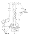
- die Förderstrecke der Tuben oder Hülsen von der Abgabestel le des Kompensators bis zur Abfüllung in die Schachtel;
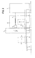
Figur 2- eine schematische Darstellung des Kompensators;
Figur 3- einen Seitenaufriss der gesamten Maschine und
- Figur 4
- eine schematische Darstellung der Abgabe der Tuben oder Hülsen vom Kompensator auf das Blech des Schlittens.
- Figure 1
- the conveying distance of the tubes or sleeves from the delivery point of the expansion joint to the filling in the box;
- Figure 2
- a schematic representation of the compensator;
- Figure 3
- a side elevation of the entire machine and
- Figure 4
- a schematic representation of the delivery of the tubes or sleeves from the compensator to the sheet metal of the carriage.
Anlagen zur Fertigung von Tuben sind ausserordentlich kostspielige Grossanlagen, die möglichst ohne Unterbruch und mit voller Kapazität betrieben werden müssen. Ein intermitierender Betrieb ist weder wünschenswert noch möglich. In der Figur 1 sind die von der Produktionsanlage 1 kontinuierlich ankommenden Tuben oder Hülsen in der Zeichnung rechts erkennbar. Die Zuführung auf einem Förderband wie hier dargestellt, hat selbstverständlich nur Symbolcharakter. Die eigentliche Tubenabpackmaschine ist gesamthaft in der Figur 1 mit der Bezugszahl 2 bezeichnet und in der Figur 3 nochmals in Seitenansicht dargestellt. Die Hauptbaugruppen der Abpackmaschine sind der Kompensator 3, der Schachtelförderer 10, sowie die elektronische Steuerung 11. Die von der Produktionsanlage kontinuierlich kommenden Hülsen oder Tuben werden somit an den Kompensator abgegeben, von wo aus sie zum Schachtelförderer (10) transportiert werden und in diesem schichtweise gruppiert in die Schachteln 9 geschoben werden. Sowohl Kompensatoren wie auch Schachtelförderer sind an sich bekannt. Gegenstand der vorliegenden Erfindung ist die Förderung der Tuben oder Hülsen vom Kompensator 3 zum Schachtelförderer 10 und von hier in die Schachtel 9. Die Schachtel 9 wird auf einem Förderband 12 in den Schachtelförderer 10 transportiert und hier entsprechend hochgehoben, so dass die Tuben schichtweise in die Schachtel 9 geschoben werden können, worauf die Schachtel um die Höhe einer Schicht abgesenkt wird und die nächste Schicht Tuben eingeschoben werden kann. Ist die Schachtel 9 vollständig gefüllt, so wird sie zur Seite geschoben und gleitet auf der Rollenbahn 13 zur Spedition.Plants for the production of tubes are extraordinarily expensive large-scale plants that have to be operated without interruption and at full capacity if possible. Intermittent operation is neither desirable nor possible. The tubes or sleeves arriving continuously from the production plant 1 can be seen in the drawing on the right in FIG. The feed on a conveyor belt as shown here is of course only symbolic. The actual tube packaging machine is designated in its entirety in FIG. 1 by the
Zur Förderung der Tuben oder Hülsen vom Kompensator 3 in die Schachtel 9, ist ein Fördermittel in Form eines Schlittens 4 vorgesehen. Der Schlitten 4 rollt auf Schienen 5, die sich mindestens vom Kompensator 3 bis in den Bereich erstrecken, in dem die Tuben vom Schlitten 4 in die bereitstehende Schachtel 9 geschoben werden. Dies bewerkstelligt die quer zur Bewegungsrichtung des Schlittens 4 gerichtete Querschieber 8. Der Schlitten 4, der auf den Schienen 5 rollt, wird von einem Schrittmotor 6 über eine Spindel 7 bewegt. Der Schrittmotor könnnte selbstverständlich auch über einen Zahnriemen den Schlitten 4 nach Massgabe des Steuerprogrammes hin- und herbewegen. In einem Takt, der schneller ist als der Takt, indem die Tuben oder Hülsen kontinuierlich von der Produktionsanlage kommen, wird der Schlitten 4 schrittweise bewegt. Der Weg des Schlittens pro Schritt entspricht der Einteilung 45 des Bleches 44 (siehe Figur 4). Ist auf dem Blech 44 die erforderliche Anzahl Tuben abgelegt, die zur Bildung einer Schicht erforderlich ist, so wird der Kompensator 3 im Bereich seiner Abgabestelle 38 gestoppt und der Schlitten 4 bewegt sich soweit zur Seite, dass er auf die Schachtel 9 ausgerichtet ist und die Tuben oder Hülsen mittels dem Querschieber 8 vom Blech 44 hinuntergeschoben werden können. Hierauf wird der Schlitten 4 auf den Schienen 5 wiederum vollständig nach rechts verschoben, so dass der nächsten Abgabe einer Tube oder Hülse vom Kompensator die weiteste links liegende Einteilung 45 gefüllt wird und nun wiederum der Schlitten schrittweise nach links verschoben werden kann.To promote the tubes or sleeves from the
Die direkte Einschiebung der Tuben in die Schachtel 9 ist eine besonders preiswerte Möglichkeit, bedingt jedoch eine gute Karton Qualität. Will man jedoch mit einer maximalen Kadenz arbeiten, so darf auch die Zeit zur Auswechslung der Schachtel 9 nur sehr kurz sein. Dies lässt sich erreichen, indem man die Tuben nicht direkt in die Schachtel schiebt, sondern erst auf einen Zwischenträger, der alle Tuben miteinander, die einer Schachtelfüllung entsprechen, in die Schachtel schiebt. Während dieser Zeit werden die Tuben auf einen Hilfszwischenträger geschoben bis der Hauptzwischenträger wieder frei ist, worauf die auf dem Hilfszwischenträger liegenden Tuben auf den Hauptzwischenträger abgegeben werden. Dieses System ist bereits aus der Schweizer Patentschrift Nr. 658'632 bekannt und hierin ausführlich beschrieben.The direct insertion of the tubes into the
Eine eminente Bedeutung bekommt bei diesem Verfahren der Kompensator. Daher ist ein für diese Maschine besonders bevorzugter Kompensator in Figur 2 dargestellt. Im Wesentlichen besteht der Kompensator aus zwei parallelen, gleichlaufenden, endlosen Ketten 30 zwischen denen Gondeln 31 angelegt sind. Die Gondeln 31 dienen dem Transport der Hülsen oder Tuben. In der Zeichnung sind lediglich einige Gondeln 31 dargestellt, während in Wirklichkeit dicht aneinander gereiht eine Gondel der andern Gondel folgt. Die über Umlenkrollen 32 laufenden Ketten 30 werden von einer Antriebswalze 33 bewegt. In der Figur ganz links ist die Ladestelle 37, an der die von der Produktionsanlage kommenden Tuben oder Hülsen in die Gondeln 31 abgegeben werden. Hier muss die Kette 30 kontinuierlich und synchron mit dem Förderband der Produktionsanlage laufen. Nur so ist gesichert, dass sämtliche von der Produktion kommenden Tuben ohne Unterbruch abgenommen werden können. Diese Synchronisation der Geschwindigkeit wird erreicht durch einen Synchron-Antrieb 39, der direkt an der Produktionslinie mechanisch gekoppelt ist. Von der Ladestelle 37 laufen die Gondeln 31 abwärts bis zum tiefsten Punkt, worauf die Kette 30 in einer ersten Schlaufe 35 aufwärts und wieder abwärts geführt wird, wiederum zum tiefsten Punkt und wird von dort zur Abgabestelle 38 geleitet. Dieser Bereich ist in Figur 4 deutlich dargestellt. Von der Abgabestelle 38 läuft die endlose Kette 30 über eine Bremswalze 34 bis zum höchsten Punkt und wird von dort wiederum abwärts und danach wieder aufwärts in Form einer zweiten Schlaufe geführt. Am Ende der zweiten Schlaufe wird die endlose Kette 30 wieder abwärts zur Ladestelle 37 und dann über die Antriebswalze 33 geführt. Die beiden Schlaufen 35 und 36 werden über Umlenkrollen geführt, die auf einem auf- und abfahrbaren Rahmen 42 angeordnet sind. Dieser fahrbare Rahmen 42 wird mittels einer Kette 43, die am Rahmen 42 befestigt ist und über eine obere Umlenkrolle und einer unteren Antriebsrolle läuft bewegt. Der Antrieb dieser Kette 43 erfolgt passiv durch die Kupplungseinheit 40 und die Bremseinheit 41, die zeitlich gegengleich zur Bremse 34 arbeitet.The compensator is of great importance in this process. A compensator which is particularly preferred for this machine is therefore shown in FIG. The compensator essentially consists of two parallel, parallel, endless chains 30 between which
Im Takt der ankommenden Gondeln 31 wird der Schlitten 4 bewegt und die Tuben oder Hülsen an der Abgabestelle 38 auf das vorherbeschriebene Blech 44 abgelegt. Ist der Schlitten beziehungsweise das Blech 44 mit der erforderlichen Anzahl Tuben gefüllt, so muss die Abgabe der Tuben kurzfristig gestoppt werden. Hierzu wird die Bremswalze 34 angehalten. Die kontinuierlich laufende Antriebswalze 33 läuft jedoch weiter. Somit wird die Schlaufe 36 in der lauter leere Gondeln 31 sind, verkürzt. An der Ladestelle 37 läuft die Kette 30 somit kontinuierlich weiter. In gleichem Masse wie die Schlaufe 36 verkürzt wird, läuft der Rahmen 42 freilaufend aufwärts und die Schlaufe 35 wird entsprechend vergrössert. Ist das Blech 44 geleert und der Schlitten 4 wieder in seine Ausgangsposition zurückgebracht, so darf die Kette im Abgabebereich 38 wieder laufen, das heisst die Bremswalze 34 darf wieder gelöst werden. Nun ist aber die Schlaufe 35 mit lauter gefüllten Gondeln 31 gross und die Schlaufe 36 mit leeren Gondeln klein. Beim nächsten Stop der Kette 30 an der Abgabestelle 38 wäre die Schlaufe 36 vermutlich zu kurz, das heisst es wären nicht genügend leere Gondeln vorhanden, die zwischenzeitlich an der Ladestelle 37 gefüllt werden können. Daher wird die Bremseinheit 41 angesteuert, die den fahrbaren Rahmen 42 über die Kette 43 wieder in seine untere Ausgangslage zieht. Dies bedeutet, dass zur kontinuierlichen Antriebsgeschwindigkeit an der Antriebswalze 33 noch eine zusätzliche Geschwindigkeitskomponente an der Abgabestelle 38 auftritt, die der Verkürzung der Schlaufe 35 entspricht. Auf diese Art kann bei der Ladestelle 37 ein kontinuierlicher Betrieb und an der Abgabestelle 38 ein intermitierender Betrieb sichergestellt werden. Die unterschiedliche Abgabegeschwindigkeit der Tuben auf das Blech 44 des Schlittens 4 bedingt, dass der Schlitten 4 nach Massgabe der Geschwindigkeit der endlosen Kette 30 im Bereich der Abgabestelle bewegt wird. Der Schrittmotor 6, der über die Spindel 7 oder Zahnriemen den Schlitten 4 bewegt, muss folglich nach Massgabe der Geschwindigkeit der Umlenkwalze 32 im Bereich der Abgabestelle 38 getaktet werden. Daher wird dessen Drehgeschwindigkeit elektronisch abgetastet und in der elektronischen Steuerung 11 ausgewertet und entsprechende Steuerpulse an den Schrittmotor 6 geliefert.The slide 4 is moved in time with the arriving
Die auf der Produktionsanlage gefertigten Tuben oder Hülsen werden vollautomatisch geprüft, und falls sie nicht den Erfordernissen entsprechen, ausgestossen. Dies bedeutet, dass nicht jede zur Abgabestelle 38 gelangende Gondel 31, auch mit einer Tube gefüllt ist. Dies muss erst elektronisch festgestellt werden, damit auf dem Blech 44 nicht eine Einteilung 45 leer bleibt. In der Figur 4 ist gezeigt, wie dies geschieht. Die in Abständen X nacheinander ankommenden Gondeln 31 stossen an ein Führungsblech 47, wodurch die Gondeln 31 um 90°gekippt werden, aber gleichzeitig die darin lagernden Tuben oder Hülsen gegen ein Herausgleiten schützt, da die Gondeln 31 nun durch das Führungsblech 47 abgedeckt sind. Ueber das Führungsblech 47 gleitend werden die Gondeln über den Bereich der Schienen 5 geführt, auf denen der Schlitten 4 rollt. Der unter das Führungsblech 47 schiebbare Schlitten 4 mit seinem Blech 44 wird nun schrittweise entsprechend der Einteilung 45 soweit unter dem Führungsblech 47 herausgezogen, dass immer die nächstfolgende Tube oder Hülse am Ende des Führungsbleches aus der Gondel 31 in die freie Einteilung 45 des Bleches 44 fällt.The tubes or sleeves manufactured on the production line are checked fully automatically and, if they do not meet the requirements, ejected. This means that not every
Das Vorhandensein einer Tube oder Hülse der Gondel 31 wird mittels einer Fotozelle 46 geprüft. Da die Gondeln oder Schalen 31 für alle Tuben- oder Hülsengrösssen gleich ist, können kleinere Tuben innerhalb der Gondel 31 hin- und herrollen. Dies könnte zu Mehrfach-Schaltungen führen. Um dies zu vermeiden, wird auch die Fotozelle 46 im Rhythmus der ankommenden Gondeln 31 getaktet. Innerhalb einer Taktzeit kann die Fotozelle nur einmal schalten. Damit sind unerwünschte Fehlschaltungen ausgeschlossen.The presence of a tube or sleeve of the
Das erfindungsgemässe Verfahren und die danach arbeitende Maschine erlaubt nun eine hohe Flexibilität. Wird zum Beispiel die Grösse der Tube in der Produktionsanlage geändert, so muss nun lediglich das Blech 44 auf dem Schlitten ausgewechselt werden durch ein anderes Blech 44 mit einer der neuen Tubengrösse angepassten Einteilung 45. Die weiteren Aenderungen, die sich hieraus ergeben, wie Beispiel die Zahl der Tuben pro Schicht und den seitlichen Verschiebungsweg des Schlittens 4 lassen sich über eine Progammsteuerung eingeben. Die gesamte Aenderung der Maschine auf das geänderte Format, ist somit eine Sache von wenigen Minuten. Aber auch die Aenderung des Schachtelformates bei gleichbleibender Grösse der Tuben ist überhaupt kein Problem mehr. Die entsprechenden Aenderung können direkt in die Programmsteuerung eingegeben werden. Entsprechend wird einfach das Blech 44 mit mehr oder wenig Tuben belegt. Der seitliche Verschiebungsweg wird entsprechend dem neuen Schachtel format angepasst. Ferner kann mit dieser neuen Maschine auch wechselweise die Anzahl der Tuben pro Schicht um jeweils eine Tube geändert werden, wodurch die dichteste Tubenpackung in der Schachtel ermöglicht wird. Auch dies ist lediglich eine Sache der Progammierung. Eine derartige Schichtung der Tuben oder Hülsen war mit den bisherigen Abpackmaschinen nicht erreichbar.The method according to the invention and the machine operating according to it now allow a high degree of flexibility. If, for example, the size of the tube in the production plant is changed, then the
Um die Taktzeit der Maschine zu erhöhen, ist es auch möglich mit zwei Schlitten zu arbeiten. Jeder Schlitten ist dann einseitig an einer Schiene gelagert gehalten und beispielsweise mit einem Hubzylinder ausgerüstet. So ist es möglich, den ersten Schlitten zur Seite zu fahren und den zweiten Schlitten, wie zuvor beschrieben, zu beladen. Der erste Schlitten wird, wie bisher entladen und wird darauf mit dem Hubzylinder abgesenkt, so dass er unter den zweiten Schlitten, der sich nun auf der oberen Ebene bewegt, hindurch zu fahren. Am Ende im Bereich der Abgabestation wartet er nun unterhalb des zweiten Schlitten bis dieser beladen zur Seite fährt. Nun wird der erste Schlitten wieder hochgehoben in seiner ursprünglichen Ausgangslage bei der Abgabestation. Auf diese Weise kann die Taktzeit verkürzt, das Verfahren somit beschleunigt und zudem der Kompensator verkleinert werden, der nun eine kleinere Pufferzeit überbrücken muss. Eine solche Maschine kann auch mit zwei Schlitten nach dem Verfahren mit einem Schlitten betrieben werden, was dann sinnvoll ist, wenn mit derselben Maschine zwei verschiedene Hüllen-, Dosen- oder Tubengrössen abwechseln verarbeitet werden müssen, ohne dass man jedesmal die Maschine umrüsten will.To increase the cycle time of the machine, it is also possible to work with two slides. Each slide is then held on one side on a rail and equipped, for example, with a lifting cylinder. It is thus possible to drive the first sled to the side and load the second sled as described above. The first carriage is unloaded as before and is then lowered with the lifting cylinder so that it is under the drive through the second sledge, which is now moving on the upper level. At the end in the area of the delivery station, he now waits below the second carriage until it loads to the side. Now the first carriage is lifted up again in its original starting position at the delivery station. In this way, the cycle time can be shortened, the process can be accelerated and the compensator can be reduced, which now has to bridge a shorter buffer time. Such a machine can also be operated with two slides according to the method with one sled, which is useful if two different casing, can or tube sizes have to be processed alternately with the same machine, without having to retool the machine each time.
Claims (10)
Priority Applications (1)
| Application Number | Priority Date | Filing Date | Title |
|---|---|---|---|
| AT90810993T ATE91986T1 (en) | 1990-01-25 | 1990-12-17 | PROCESS FOR PACKING CASES OR TUBES IN BOXES, AND MACHINE FOR CARRYING OUT THE PROCESS. |
Applications Claiming Priority (4)
| Application Number | Priority Date | Filing Date | Title |
|---|---|---|---|
| CH23390 | 1990-01-25 | ||
| CH233/90 | 1990-01-25 | ||
| CH397190A CH682385A5 (en) | 1990-12-14 | 1990-12-14 | Packing hoses, sleeves or tubes into boxes |
| CH3971/90 | 1990-12-14 |
Publications (2)
| Publication Number | Publication Date |
|---|---|
| EP0438974A1 true EP0438974A1 (en) | 1991-07-31 |
| EP0438974B1 EP0438974B1 (en) | 1993-07-28 |
Family
ID=25683967
Family Applications (1)
| Application Number | Title | Priority Date | Filing Date |
|---|---|---|---|
| EP90810993A Expired - Lifetime EP0438974B1 (en) | 1990-01-25 | 1990-12-17 | Method for packaging sleeves or tubes in boxes, and machine for executing the method |
Country Status (4)
| Country | Link |
|---|---|
| US (1) | US5060454A (en) |
| EP (1) | EP0438974B1 (en) |
| DE (1) | DE59002105D1 (en) |
| ES (1) | ES2047305T3 (en) |
Cited By (6)
| Publication number | Priority date | Publication date | Assignee | Title |
|---|---|---|---|---|
| EP0594917A1 (en) * | 1991-04-04 | 1994-05-04 | Pamag Ag | Method for taking over continuously delivered products from a production device and for delivering discontinuously a number of those products in a delivering station |
| DE4433808A1 (en) * | 1994-09-22 | 1996-03-28 | Focke & Co | Method and device for handling cylindrical objects, in particular biscuit rolls |
| WO1999014033A2 (en) * | 1997-09-18 | 1999-03-25 | Ranpak Corp. | Dunnage pad production and packaging system |
| EP1123867A1 (en) | 2000-02-08 | 2001-08-16 | Texa AG | Machine for packaging tubes |
| EP1394081A3 (en) * | 2002-08-08 | 2007-07-25 | Texa AG | Transfer chain conveyor for receiving discontinuously sleeves or tubes from a producing machine |
| EP2192061A2 (en) | 2008-12-01 | 2010-06-02 | Texa AG | Device for transferring, intermediate storage and forwarding of lengthwise, hollow cylinder product units and method of operating such a device |
Families Citing this family (16)
| Publication number | Priority date | Publication date | Assignee | Title |
|---|---|---|---|---|
| US5528878A (en) * | 1994-06-10 | 1996-06-25 | Johnson & Johnson Vision Products, Inc. | Automated apparatus and method for consolidating products for packaging |
| CH690712A5 (en) * | 1995-11-17 | 2000-12-29 | Hinterkopf Gmbh | Method and apparatus for packing of tins or tubes. |
| SG50380A1 (en) * | 1995-12-09 | 1998-07-20 | Advanced Systems Automation Pt | Pick and place system |
| CH691899A5 (en) * | 1996-10-17 | 2001-11-30 | Hinterkopf Gmbh | Method and apparatus for packaging cans or tubes. |
| US6141943A (en) * | 1998-09-21 | 2000-11-07 | F. R. Drake Company | Food article loading head and method |
| EP1114784B1 (en) * | 2000-01-04 | 2002-10-30 | Texa AG | Device for forming groups of products |
| ITBO20020526A1 (en) * | 2002-08-08 | 2004-02-09 | Gd Spa | METHOD AND DEVICE FOR THE FORMATION OF GROUPS OF PRODUCTS. |
| WO2005019035A1 (en) * | 2003-08-20 | 2005-03-03 | Texa Ag | Method and device for packing tubes |
| US7598683B1 (en) | 2007-07-31 | 2009-10-06 | Lsi Industries, Inc. | Control of light intensity using pulses of a fixed duration and frequency |
| US8903577B2 (en) | 2009-10-30 | 2014-12-02 | Lsi Industries, Inc. | Traction system for electrically powered vehicles |
| US8604709B2 (en) | 2007-07-31 | 2013-12-10 | Lsi Industries, Inc. | Methods and systems for controlling electrical power to DC loads |
| US20110124276A1 (en) * | 2009-11-24 | 2011-05-26 | Momence Packing Co. | Link loader |
| CN103287621B (en) * | 2013-05-20 | 2016-03-02 | 青岛非凡包装机械有限公司 | The automatic arranging machine of many rows multiple row |
| DE102017101464A1 (en) * | 2017-01-25 | 2018-07-26 | Vemag Maschinenbau Gmbh | Device and method for transferring and placing sausage groups in a package |
| CN111137500A (en) * | 2019-12-31 | 2020-05-12 | 登封市启明轩程控设备有限公司 | Cylindrical material layering arrangement device and paper-packaged fine dried noodle bagging machine |
| CN113978817B (en) * | 2021-10-31 | 2023-08-15 | 盈锋紧固系统(南通)有限公司 | Packing device for rivet nut |
Citations (3)
| Publication number | Priority date | Publication date | Assignee | Title |
|---|---|---|---|---|
| US3479795A (en) * | 1966-10-31 | 1969-11-25 | Carnation Co | Automatic packaging apparatus |
| GB1274222A (en) * | 1968-05-17 | 1972-05-17 | Redman Heenan Internat Ltd | Improvements in or relating to box loading apparatus |
| FR2261183A1 (en) * | 1974-02-16 | 1975-09-12 | Focke Pfuhl Verpack Automat |
Family Cites Families (11)
| Publication number | Priority date | Publication date | Assignee | Title |
|---|---|---|---|---|
| US3107013A (en) * | 1959-09-07 | 1963-10-15 | Lever Brothers Ltd | Method and means for stacking articles |
| GB1061984A (en) * | 1963-10-25 | 1967-03-15 | Kurt Koerber | Apparatus for manipulating rod-shaped articles |
| US3517478A (en) * | 1967-11-17 | 1970-06-30 | Federal Cartridge Corp | Cartridge packaging machine |
| DE2138926C3 (en) * | 1971-08-04 | 1981-07-23 | Zinser Textilmaschinen Gmbh, 7333 Ebersbach | Device for the automatic transport and storage of cops in groups |
| DE3137948C2 (en) * | 1981-09-24 | 1983-09-29 | Maschinenfabrik Alfred Schmermund Gmbh & Co, 5820 Gevelsberg | "Storage for packs" |
| CH658632A5 (en) * | 1982-12-08 | 1986-11-28 | Lesieur Cotelle S A Soc | METHOD FOR PACKING HOSE BAGS IN BOXES, AND DEVICE FOR IMPLEMENTING THE METHOD. |
| US4607477A (en) * | 1983-04-15 | 1986-08-26 | Molins Plc | Cigarette packing machines |
| US4571917A (en) * | 1983-09-28 | 1986-02-25 | Philip Morris Incorporated | Apparatus for packing oval cigarettes |
| US4633653A (en) * | 1984-10-29 | 1987-01-06 | Roberts John T | Case packing apparatus |
| US4633652A (en) * | 1986-02-04 | 1987-01-06 | Les Epiciers Unis Metro-Richelieu Inc. | Method and apparatus for automatically packing sausage links |
| JPS63192370A (en) * | 1987-02-05 | 1988-08-09 | 日本たばこ産業株式会社 | Filling apparatus of rod-shaped article |
-
1990
- 1990-12-17 EP EP90810993A patent/EP0438974B1/en not_active Expired - Lifetime
- 1990-12-17 DE DE9090810993T patent/DE59002105D1/en not_active Expired - Fee Related
- 1990-12-17 ES ES90810993T patent/ES2047305T3/en not_active Expired - Lifetime
-
1991
- 1991-01-24 US US07/645,895 patent/US5060454A/en not_active Expired - Fee Related
Patent Citations (3)
| Publication number | Priority date | Publication date | Assignee | Title |
|---|---|---|---|---|
| US3479795A (en) * | 1966-10-31 | 1969-11-25 | Carnation Co | Automatic packaging apparatus |
| GB1274222A (en) * | 1968-05-17 | 1972-05-17 | Redman Heenan Internat Ltd | Improvements in or relating to box loading apparatus |
| FR2261183A1 (en) * | 1974-02-16 | 1975-09-12 | Focke Pfuhl Verpack Automat |
Cited By (12)
| Publication number | Priority date | Publication date | Assignee | Title |
|---|---|---|---|---|
| EP0594917A1 (en) * | 1991-04-04 | 1994-05-04 | Pamag Ag | Method for taking over continuously delivered products from a production device and for delivering discontinuously a number of those products in a delivering station |
| DE4433808A1 (en) * | 1994-09-22 | 1996-03-28 | Focke & Co | Method and device for handling cylindrical objects, in particular biscuit rolls |
| WO1999014033A2 (en) * | 1997-09-18 | 1999-03-25 | Ranpak Corp. | Dunnage pad production and packaging system |
| WO1999014033A3 (en) * | 1997-09-18 | 1999-08-19 | Ranpak Corp | Dunnage pad production and packaging system |
| US6421985B1 (en) | 1997-09-18 | 2002-07-23 | Ranpak Corp. | Dunnage pad production and packaging system |
| EP1498258A2 (en) * | 1997-09-18 | 2005-01-19 | Ranpak Corp. | Dunnage pad production and packaging system |
| EP1498258A3 (en) * | 1997-09-18 | 2005-08-24 | Ranpak Corp. | Dunnage pad production and packaging system |
| US7866125B2 (en) | 1997-09-18 | 2011-01-11 | Ranpak Corp. | Dunnage production and packaging |
| EP1123867A1 (en) | 2000-02-08 | 2001-08-16 | Texa AG | Machine for packaging tubes |
| EP1123867B1 (en) * | 2000-02-08 | 2004-06-30 | Texa AG | Machine for packaging tubes |
| EP1394081A3 (en) * | 2002-08-08 | 2007-07-25 | Texa AG | Transfer chain conveyor for receiving discontinuously sleeves or tubes from a producing machine |
| EP2192061A2 (en) | 2008-12-01 | 2010-06-02 | Texa AG | Device for transferring, intermediate storage and forwarding of lengthwise, hollow cylinder product units and method of operating such a device |
Also Published As
| Publication number | Publication date |
|---|---|
| ES2047305T3 (en) | 1994-02-16 |
| DE59002105D1 (en) | 1993-09-02 |
| US5060454A (en) | 1991-10-29 |
| EP0438974B1 (en) | 1993-07-28 |
Similar Documents
| Publication | Publication Date | Title |
|---|---|---|
| EP0438974B1 (en) | Method for packaging sleeves or tubes in boxes, and machine for executing the method | |
| DE3625212C2 (en) | Workpiece transfer device | |
| EP2097324B1 (en) | Method for controlling the transfer of a product stack in a packaging machine | |
| EP0732279B1 (en) | System for storing articles | |
| AT13828U1 (en) | Picking system and method for loading of load carriers | |
| CH437120A (en) | Machine for the fast, gentle conveying of fragile objects, e.g. Eggs, for packing the same | |
| DE2315176A1 (en) | MACHINE FOR PACKAGING FLEXIBLE ITEMS | |
| DE2022602A1 (en) | Plant with several packing machines, especially for cigarettes | |
| EP0538742B1 (en) | Storage for goods pieces | |
| DE112005000890T5 (en) | Method and device for temporarily storing articles | |
| DE6610240U (en) | DEVICE FOR UNLOADING CIGARETTE COLLARS OD. DGL. CONTAIN. | |
| DE2758652A1 (en) | PROCEDURE AND SYSTEM FOR PROMOTING OBJECTS | |
| DE10316853A1 (en) | Process for automatic packaging of containers | |
| DE2824304A1 (en) | METHOD FOR FEEDING FOLDING BOXES FROM A PRODUCTION DEVICE FOR THE FOLDING BOXES TO A DEVICE FOR FURTHER PROCESSING OF THE FOLDING BOXES AND PRODUCTION LINE FOR FOLDING BOXES | |
| EP2480468B1 (en) | High-speed store | |
| CH682385A5 (en) | Packing hoses, sleeves or tubes into boxes | |
| DE7713605U1 (en) | FEEDING DEVICE FOR MACHINE TOOLS | |
| DE1939536A1 (en) | Device for supplying containers filled with cigarettes to the loading mechanism of the inlet chute of a packaging machine for cigarettes to be packed in packets | |
| DE60313946T2 (en) | Device for conveying piece goods, in particular for an automatic packaging machine, and method for its use | |
| DE2510394A1 (en) | PACKAGING MACHINE | |
| DE3921907A1 (en) | DEVICE FOR THE INTERIM STORAGE OF A GOOD | |
| EP1492422B1 (en) | Device for dividing a continuous sequence of articles and corresponding method | |
| DE2301733A1 (en) | TRANSPORT SYSTEM FOR WORKPIECE CARRIERS | |
| DE102007018676A1 (en) | Method for controlling the construction and taking over of a product stack in a packaging machine | |
| EP3693299B1 (en) | Device for continuously conveying material and method for continuously conveying material |
Legal Events
| Date | Code | Title | Description |
|---|---|---|---|
| PUAI | Public reference made under article 153(3) epc to a published international application that has entered the european phase |
Free format text: ORIGINAL CODE: 0009012 |
|
| AK | Designated contracting states |
Kind code of ref document: A1 Designated state(s): AT BE CH DE DK ES FR GB GR IT LI LU NL SE |
|
| 17P | Request for examination filed |
Effective date: 19910911 |
|
| 17Q | First examination report despatched |
Effective date: 19920710 |
|
| RAP1 | Party data changed (applicant data changed or rights of an application transferred) |
Owner name: PAMAG AG |
|
| ITF | It: translation for a ep patent filed |
Owner name: STUDIO MASSARI S.R.L. |
|
| GRAA | (expected) grant |
Free format text: ORIGINAL CODE: 0009210 |
|
| AK | Designated contracting states |
Kind code of ref document: B1 Designated state(s): AT BE CH DE DK ES FR GB GR IT LI LU NL SE |
|
| PG25 | Lapsed in a contracting state [announced via postgrant information from national office to epo] |
Ref country code: SE Effective date: 19930728 Ref country code: GR Free format text: LAPSE BECAUSE OF FAILURE TO SUBMIT A TRANSLATION OF THE DESCRIPTION OR TO PAY THE FEE WITHIN THE PRESCRIBED TIME-LIMIT Effective date: 19930728 Ref country code: DK Effective date: 19930728 Ref country code: BE Effective date: 19930728 |
|
| REF | Corresponds to: |
Ref document number: 91986 Country of ref document: AT Date of ref document: 19930815 Kind code of ref document: T |
|
| ET | Fr: translation filed | ||
| GBT | Gb: translation of ep patent filed (gb section 77(6)(a)/1977) |
Effective date: 19930729 |
|
| REF | Corresponds to: |
Ref document number: 59002105 Country of ref document: DE Date of ref document: 19930902 |
|
| PG25 | Lapsed in a contracting state [announced via postgrant information from national office to epo] |
Ref country code: LU Free format text: LAPSE BECAUSE OF NON-PAYMENT OF DUE FEES Effective date: 19931231 |
|
| REG | Reference to a national code |
Ref country code: ES Ref legal event code: FG2A Ref document number: 2047305 Country of ref document: ES Kind code of ref document: T3 |
|
| PLBE | No opposition filed within time limit |
Free format text: ORIGINAL CODE: 0009261 |
|
| STAA | Information on the status of an ep patent application or granted ep patent |
Free format text: STATUS: NO OPPOSITION FILED WITHIN TIME LIMIT |
|
| 26N | No opposition filed | ||
| ITTA | It: last paid annual fee | ||
| PGFP | Annual fee paid to national office [announced via postgrant information from national office to epo] |
Ref country code: AT Payment date: 19991221 Year of fee payment: 10 |
|
| REG | Reference to a national code |
Ref country code: CH Ref legal event code: PUE Owner name: PAMAG AG TRANSFER- HINTERKOPF GMBH Ref country code: CH Ref legal event code: NV Representative=s name: TROESCH SCHEIDEGGER WERNER AG |
|
| REG | Reference to a national code |
Ref country code: GB Ref legal event code: 732E |
|
| REG | Reference to a national code |
Ref country code: ES Ref legal event code: PC2A |
|
| NLS | Nl: assignments of ep-patents |
Owner name: HINTERKOPF GMBH |
|
| REG | Reference to a national code |
Ref country code: FR Ref legal event code: TP |
|
| PGFP | Annual fee paid to national office [announced via postgrant information from national office to epo] |
Ref country code: GB Payment date: 20001123 Year of fee payment: 11 |
|
| PGFP | Annual fee paid to national office [announced via postgrant information from national office to epo] |
Ref country code: NL Payment date: 20001127 Year of fee payment: 11 Ref country code: DE Payment date: 20001127 Year of fee payment: 11 |
|
| PGFP | Annual fee paid to national office [announced via postgrant information from national office to epo] |
Ref country code: FR Payment date: 20001204 Year of fee payment: 11 |
|
| PG25 | Lapsed in a contracting state [announced via postgrant information from national office to epo] |
Ref country code: AT Free format text: LAPSE BECAUSE OF NON-PAYMENT OF DUE FEES Effective date: 20001217 |
|
| PGFP | Annual fee paid to national office [announced via postgrant information from national office to epo] |
Ref country code: ES Payment date: 20001218 Year of fee payment: 11 |
|
| PGFP | Annual fee paid to national office [announced via postgrant information from national office to epo] |
Ref country code: CH Payment date: 20010301 Year of fee payment: 11 |
|
| PG25 | Lapsed in a contracting state [announced via postgrant information from national office to epo] |
Ref country code: GB Free format text: LAPSE BECAUSE OF NON-PAYMENT OF DUE FEES Effective date: 20011217 |
|
| PG25 | Lapsed in a contracting state [announced via postgrant information from national office to epo] |
Ref country code: LI Free format text: LAPSE BECAUSE OF NON-PAYMENT OF DUE FEES Effective date: 20011231 Ref country code: CH Free format text: LAPSE BECAUSE OF NON-PAYMENT OF DUE FEES Effective date: 20011231 |
|
| REG | Reference to a national code |
Ref country code: GB Ref legal event code: IF02 |
|
| PG25 | Lapsed in a contracting state [announced via postgrant information from national office to epo] |
Ref country code: NL Free format text: LAPSE BECAUSE OF NON-PAYMENT OF DUE FEES Effective date: 20020701 |
|
| PG25 | Lapsed in a contracting state [announced via postgrant information from national office to epo] |
Ref country code: DE Free format text: LAPSE BECAUSE OF NON-PAYMENT OF DUE FEES Effective date: 20020702 |
|
| GBPC | Gb: european patent ceased through non-payment of renewal fee |
Effective date: 20011217 |
|
| REG | Reference to a national code |
Ref country code: CH Ref legal event code: PL |
|
| PG25 | Lapsed in a contracting state [announced via postgrant information from national office to epo] |
Ref country code: FR Free format text: LAPSE BECAUSE OF NON-PAYMENT OF DUE FEES Effective date: 20020830 |
|
| NLV4 | Nl: lapsed or anulled due to non-payment of the annual fee |
Effective date: 20020701 |
|
| REG | Reference to a national code |
Ref country code: FR Ref legal event code: ST |
|
| PG25 | Lapsed in a contracting state [announced via postgrant information from national office to epo] |
Ref country code: ES Free format text: LAPSE BECAUSE OF NON-PAYMENT OF DUE FEES Effective date: 20021218 |
|
| REG | Reference to a national code |
Ref country code: ES Ref legal event code: FD2A Effective date: 20030113 |
|
| PG25 | Lapsed in a contracting state [announced via postgrant information from national office to epo] |
Ref country code: IT Free format text: LAPSE BECAUSE OF NON-PAYMENT OF DUE FEES;WARNING: LAPSES OF ITALIAN PATENTS WITH EFFECTIVE DATE BEFORE 2007 MAY HAVE OCCURRED AT ANY TIME BEFORE 2007. THE CORRECT EFFECTIVE DATE MAY BE DIFFERENT FROM THE ONE RECORDED. Effective date: 20051217 |