EP0440045A2 - Valuable document with optically variable security element - Google Patents
Valuable document with optically variable security element Download PDFInfo
- Publication number
- EP0440045A2 EP0440045A2 EP91100533A EP91100533A EP0440045A2 EP 0440045 A2 EP0440045 A2 EP 0440045A2 EP 91100533 A EP91100533 A EP 91100533A EP 91100533 A EP91100533 A EP 91100533A EP 0440045 A2 EP0440045 A2 EP 0440045A2
- Authority
- EP
- European Patent Office
- Prior art keywords
- data carrier
- optically variable
- paper
- smoothed
- coating
- Prior art date
- Legal status (The legal status is an assumption and is not a legal conclusion. Google has not performed a legal analysis and makes no representation as to the accuracy of the status listed.)
- Granted
Links
- 238000007639 printing Methods 0.000 claims abstract description 52
- 238000000034 method Methods 0.000 claims description 62
- 238000004519 manufacturing process Methods 0.000 claims description 52
- 238000000576 coating method Methods 0.000 claims description 40
- 238000009499 grossing Methods 0.000 claims description 40
- 239000011248 coating agent Substances 0.000 claims description 38
- 239000004922 lacquer Substances 0.000 claims description 13
- 238000003490 calendering Methods 0.000 claims description 12
- 150000001875 compounds Chemical class 0.000 claims description 10
- 238000005266 casting Methods 0.000 claims description 9
- 239000002318 adhesion promoter Substances 0.000 claims description 6
- 238000001035 drying Methods 0.000 claims description 6
- 230000001681 protective effect Effects 0.000 claims description 6
- 238000007646 gravure printing Methods 0.000 claims description 4
- 230000006835 compression Effects 0.000 claims 2
- 238000007906 compression Methods 0.000 claims 2
- 239000010410 layer Substances 0.000 description 41
- 238000012546 transfer Methods 0.000 description 33
- 230000008569 process Effects 0.000 description 32
- 230000003287 optical effect Effects 0.000 description 20
- 239000000758 substrate Substances 0.000 description 17
- 238000004049 embossing Methods 0.000 description 13
- 239000000853 adhesive Substances 0.000 description 10
- 230000001070 adhesive effect Effects 0.000 description 10
- 230000008901 benefit Effects 0.000 description 10
- 239000012790 adhesive layer Substances 0.000 description 9
- 238000005516 engineering process Methods 0.000 description 8
- 238000012545 processing Methods 0.000 description 8
- 229910000831 Steel Inorganic materials 0.000 description 7
- 229910052751 metal Inorganic materials 0.000 description 7
- 239000002184 metal Substances 0.000 description 7
- 239000010959 steel Substances 0.000 description 7
- 230000003746 surface roughness Effects 0.000 description 7
- 239000000463 material Substances 0.000 description 5
- 230000001680 brushing effect Effects 0.000 description 4
- 238000010422 painting Methods 0.000 description 4
- 239000004033 plastic Substances 0.000 description 4
- 241000196324 Embryophyta Species 0.000 description 3
- 239000004831 Hot glue Substances 0.000 description 3
- 238000004804 winding Methods 0.000 description 3
- 229920000106 Liquid crystal polymer Polymers 0.000 description 2
- 239000004977 Liquid-crystal polymers (LCPs) Substances 0.000 description 2
- 238000004026 adhesive bonding Methods 0.000 description 2
- 239000000969 carrier Substances 0.000 description 2
- 238000013461 design Methods 0.000 description 2
- 230000000694 effects Effects 0.000 description 2
- 238000010894 electron beam technology Methods 0.000 description 2
- 230000006872 improvement Effects 0.000 description 2
- 239000000976 ink Substances 0.000 description 2
- 229910052500 inorganic mineral Inorganic materials 0.000 description 2
- 239000011707 mineral Substances 0.000 description 2
- 239000000049 pigment Substances 0.000 description 2
- 238000009417 prefabrication Methods 0.000 description 2
- 239000011241 protective layer Substances 0.000 description 2
- 230000005855 radiation Effects 0.000 description 2
- 238000005096 rolling process Methods 0.000 description 2
- 238000010023 transfer printing Methods 0.000 description 2
- 206010013786 Dry skin Diseases 0.000 description 1
- 240000005702 Galium aparine Species 0.000 description 1
- 239000004820 Pressure-sensitive adhesive Substances 0.000 description 1
- 230000009471 action Effects 0.000 description 1
- 229910052782 aluminium Inorganic materials 0.000 description 1
- XAGFODPZIPBFFR-UHFFFAOYSA-N aluminium Chemical compound [Al] XAGFODPZIPBFFR-UHFFFAOYSA-N 0.000 description 1
- 238000013459 approach Methods 0.000 description 1
- 239000011230 binding agent Substances 0.000 description 1
- 239000008199 coating composition Substances 0.000 description 1
- 239000003086 colorant Substances 0.000 description 1
- 238000010924 continuous production Methods 0.000 description 1
- 230000008878 coupling Effects 0.000 description 1
- 238000010168 coupling process Methods 0.000 description 1
- 238000005859 coupling reaction Methods 0.000 description 1
- 238000011161 development Methods 0.000 description 1
- 230000018109 developmental process Effects 0.000 description 1
- 239000000835 fiber Substances 0.000 description 1
- 239000000945 filler Substances 0.000 description 1
- 230000010354 integration Effects 0.000 description 1
- 238000002372 labelling Methods 0.000 description 1
- 238000010030 laminating Methods 0.000 description 1
- 238000003475 lamination Methods 0.000 description 1
- 230000007246 mechanism Effects 0.000 description 1
- 239000000155 melt Substances 0.000 description 1
- 238000012986 modification Methods 0.000 description 1
- 230000004048 modification Effects 0.000 description 1
- 239000003973 paint Substances 0.000 description 1
- 239000002245 particle Substances 0.000 description 1
- 238000005293 physical law Methods 0.000 description 1
- 229920001296 polysiloxane Polymers 0.000 description 1
- 238000003825 pressing Methods 0.000 description 1
- 238000003908 quality control method Methods 0.000 description 1
- 230000000717 retained effect Effects 0.000 description 1
- 238000007761 roller coating Methods 0.000 description 1
- 238000003892 spreading Methods 0.000 description 1
- 230000007480 spreading Effects 0.000 description 1
- 238000003860 storage Methods 0.000 description 1
- 239000000126 substance Substances 0.000 description 1
- 238000011144 upstream manufacturing Methods 0.000 description 1
- 238000001771 vacuum deposition Methods 0.000 description 1
- 238000007740 vapor deposition Methods 0.000 description 1
- 239000002966 varnish Substances 0.000 description 1
Images
Classifications
-
- B—PERFORMING OPERATIONS; TRANSPORTING
- B41—PRINTING; LINING MACHINES; TYPEWRITERS; STAMPS
- B41F—PRINTING MACHINES OR PRESSES
- B41F19/00—Apparatus or machines for carrying out printing operations combined with other operations
- B41F19/02—Apparatus or machines for carrying out printing operations combined with other operations with embossing
- B41F19/06—Printing and embossing between a negative and a positive forme after inking and wiping the negative forme; Printing from an ink band treated with colour or "gold"
- B41F19/062—Presses of the rotary type
-
- B—PERFORMING OPERATIONS; TRANSPORTING
- B42—BOOKBINDING; ALBUMS; FILES; SPECIAL PRINTED MATTER
- B42D—BOOKS; BOOK COVERS; LOOSE LEAVES; PRINTED MATTER CHARACTERISED BY IDENTIFICATION OR SECURITY FEATURES; PRINTED MATTER OF SPECIAL FORMAT OR STYLE NOT OTHERWISE PROVIDED FOR; DEVICES FOR USE THEREWITH AND NOT OTHERWISE PROVIDED FOR; MOVABLE-STRIP WRITING OR READING APPARATUS
- B42D25/00—Information-bearing cards or sheet-like structures characterised by identification or security features; Manufacture thereof
- B42D25/20—Information-bearing cards or sheet-like structures characterised by identification or security features; Manufacture thereof characterised by a particular use or purpose
- B42D25/29—Securities; Bank notes
-
- B—PERFORMING OPERATIONS; TRANSPORTING
- B42—BOOKBINDING; ALBUMS; FILES; SPECIAL PRINTED MATTER
- B42D—BOOKS; BOOK COVERS; LOOSE LEAVES; PRINTED MATTER CHARACTERISED BY IDENTIFICATION OR SECURITY FEATURES; PRINTED MATTER OF SPECIAL FORMAT OR STYLE NOT OTHERWISE PROVIDED FOR; DEVICES FOR USE THEREWITH AND NOT OTHERWISE PROVIDED FOR; MOVABLE-STRIP WRITING OR READING APPARATUS
- B42D25/00—Information-bearing cards or sheet-like structures characterised by identification or security features; Manufacture thereof
- B42D25/30—Identification or security features, e.g. for preventing forgery
- B42D25/328—Diffraction gratings; Holograms
-
- G—PHYSICS
- G07—CHECKING-DEVICES
- G07D—HANDLING OF COINS OR VALUABLE PAPERS, e.g. TESTING, SORTING BY DENOMINATIONS, COUNTING, DISPENSING, CHANGING OR DEPOSITING
- G07D7/00—Testing specially adapted to determine the identity or genuineness of valuable papers or for segregating those which are unacceptable, e.g. banknotes that are alien to a currency
- G07D7/003—Testing specially adapted to determine the identity or genuineness of valuable papers or for segregating those which are unacceptable, e.g. banknotes that are alien to a currency using security elements
- G07D7/0032—Testing specially adapted to determine the identity or genuineness of valuable papers or for segregating those which are unacceptable, e.g. banknotes that are alien to a currency using security elements using holograms
-
- B—PERFORMING OPERATIONS; TRANSPORTING
- B41—PRINTING; LINING MACHINES; TYPEWRITERS; STAMPS
- B41P—INDEXING SCHEME RELATING TO PRINTING, LINING MACHINES, TYPEWRITERS, AND TO STAMPS
- B41P2219/00—Printing presses using a heated printing foil
- B41P2219/50—Printing presses using a heated printing foil combined with existing presses
- B41P2219/51—Converting existing presses to foil printing presses
-
- G—PHYSICS
- G03—PHOTOGRAPHY; CINEMATOGRAPHY; ANALOGOUS TECHNIQUES USING WAVES OTHER THAN OPTICAL WAVES; ELECTROGRAPHY; HOLOGRAPHY
- G03H—HOLOGRAPHIC PROCESSES OR APPARATUS
- G03H1/00—Holographic processes or apparatus using light, infrared or ultraviolet waves for obtaining holograms or for obtaining an image from them; Details peculiar thereto
- G03H1/0005—Adaptation of holography to specific applications
- G03H1/0011—Adaptation of holography to specific applications for security or authentication
-
- G—PHYSICS
- G03—PHOTOGRAPHY; CINEMATOGRAPHY; ANALOGOUS TECHNIQUES USING WAVES OTHER THAN OPTICAL WAVES; ELECTROGRAPHY; HOLOGRAPHY
- G03H—HOLOGRAPHIC PROCESSES OR APPARATUS
- G03H2250/00—Laminate comprising a hologram layer
- G03H2250/12—Special arrangement of layers
-
- G—PHYSICS
- G03—PHOTOGRAPHY; CINEMATOGRAPHY; ANALOGOUS TECHNIQUES USING WAVES OTHER THAN OPTICAL WAVES; ELECTROGRAPHY; HOLOGRAPHY
- G03H—HOLOGRAPHIC PROCESSES OR APPARATUS
- G03H2270/00—Substrate bearing the hologram
- G03H2270/10—Composition
- G03H2270/12—Fibrous, e.g. paper, textile
-
- G—PHYSICS
- G07—CHECKING-DEVICES
- G07D—HANDLING OF COINS OR VALUABLE PAPERS, e.g. TESTING, SORTING BY DENOMINATIONS, COUNTING, DISPENSING, CHANGING OR DEPOSITING
- G07D7/00—Testing specially adapted to determine the identity or genuineness of valuable papers or for segregating those which are unacceptable, e.g. banknotes that are alien to a currency
- G07D7/20—Testing patterns thereon
-
- Y—GENERAL TAGGING OF NEW TECHNOLOGICAL DEVELOPMENTS; GENERAL TAGGING OF CROSS-SECTIONAL TECHNOLOGIES SPANNING OVER SEVERAL SECTIONS OF THE IPC; TECHNICAL SUBJECTS COVERED BY FORMER USPC CROSS-REFERENCE ART COLLECTIONS [XRACs] AND DIGESTS
- Y10—TECHNICAL SUBJECTS COVERED BY FORMER USPC
- Y10S—TECHNICAL SUBJECTS COVERED BY FORMER USPC CROSS-REFERENCE ART COLLECTIONS [XRACs] AND DIGESTS
- Y10S428/00—Stock material or miscellaneous articles
- Y10S428/914—Transfer or decalcomania
- Y10S428/915—Fraud or tamper detecting
-
- Y—GENERAL TAGGING OF NEW TECHNOLOGICAL DEVELOPMENTS; GENERAL TAGGING OF CROSS-SECTIONAL TECHNOLOGIES SPANNING OVER SEVERAL SECTIONS OF THE IPC; TECHNICAL SUBJECTS COVERED BY FORMER USPC CROSS-REFERENCE ART COLLECTIONS [XRACs] AND DIGESTS
- Y10—TECHNICAL SUBJECTS COVERED BY FORMER USPC
- Y10S—TECHNICAL SUBJECTS COVERED BY FORMER USPC CROSS-REFERENCE ART COLLECTIONS [XRACs] AND DIGESTS
- Y10S428/00—Stock material or miscellaneous articles
- Y10S428/916—Fraud or tamper detecting
-
- Y—GENERAL TAGGING OF NEW TECHNOLOGICAL DEVELOPMENTS; GENERAL TAGGING OF CROSS-SECTIONAL TECHNOLOGIES SPANNING OVER SEVERAL SECTIONS OF THE IPC; TECHNICAL SUBJECTS COVERED BY FORMER USPC CROSS-REFERENCE ART COLLECTIONS [XRACs] AND DIGESTS
- Y10—TECHNICAL SUBJECTS COVERED BY FORMER USPC
- Y10T—TECHNICAL SUBJECTS COVERED BY FORMER US CLASSIFICATION
- Y10T428/00—Stock material or miscellaneous articles
- Y10T428/24—Structurally defined web or sheet [e.g., overall dimension, etc.]
- Y10T428/24802—Discontinuous or differential coating, impregnation or bond [e.g., artwork, printing, retouched photograph, etc.]
Definitions
- the invention relates to a data carrier made of paper, in particular a security, a bank note or the like with an optically variable security element applied to the surface, such as. B. a diffraction grating, hologram, interference element, liquid crystal polymer or the like with an additionally applied in a printing process, in particular a steel intaglio printing process, as well as a method and an apparatus for producing the same.
- OTD optically variable elements
- adhesive labels When gluing, adhesive labels, which are initially pre-punched on silicone paper, are transferred mechanically to the paper substrate.
- the adhesive labels have a layer structure, which is composed of a pressure-sensitive adhesive layer, a self-supporting film with an optically active layer over, for example, a diffraction grating and an overlying protective layer.
- the thickness of an adhesive label is typically around 50 micrometers, the major part of the thickness being attributable to the film material.
- the optically variable element is prefabricated on a transfer belt and transferred to the substrate in a subsequent step.
- the one transferred to the paper Structure typically has a thickness in the range of a few micrometers.
- the usual layer structure of the element consists of a hot glue layer, a lacquer layer with embossing, an aluminum vapor deposition layer and a transparent protective covering layer.
- This layer structure is initially on the transfer film, with it being "attached" to the film with a release layer (eg a wax layer).
- a release layer eg a wax layer.
- the tape with the hot-melt adhesive layer is placed on the substrate; the hot-melt adhesive layer is activated by pressing on a heated stamp, so that the element connects to the substrate.
- the separating layer melts, causing the hologram to detach from the transfer belt.
- the transfer principle is the most frequently used method today and is used in particular to apply holograms to plastic credit cards.
- the embossing process is particularly suitable for diffraction elements such as holograms and optical gratings.
- a layer of a curable lacquer is applied to a substrate, which is preferably provided with an extremely thin and reflective metal surface.
- the diffractive relief structure is embossed into the lacquer layer with an embossing stamp.
- the structure is covered with a protective lacquer.
- the finished element has a layer structure consisting of the successive layers of lacquer with a metal layer and relief structure and the protective lacquer layer.
- Adhesive labels are technically simple to produce and can be transferred to the intended substrates without any problems.
- Adhesive labels are extremely disadvantageous for use in the securities sector the possibility of detaching the elements as a whole from the substrate and transferring them to counterfeit products. For this reason, the transfer and embossing elements are preferred for security applications.
- the first point to be considered is that securities usually have a high-quality security image; in most cases, these printed images are applied using steel gravure printing processes. Gravure printing and related processes require a relatively high surface roughness of the substrate so that the printing inks bond well to the substrate. Rough surfaces, however, are unsuitable for the application of optical elements.
- EP-OS 338 378 such a system for the production of paper products which have both a printed image and an optical diffraction element.
- the paper is first printed in known printing units.
- a radiation-curable lacquer is then applied in a single operation, analogous to the embossing process described, and provided with a diffraction structure.
- the diffraction structure is vapor-coated with a reflective metal layer and provided with a protective lacquer.
- the hologram application process is divided into two. Following the paper production, the varnish is applied to the paper surface in a first sub-step. After printing on the paper, the optical grid is embossed in the next step.
- a disadvantage of the known methods is the greatly differing production speeds of printing presses and the devices which apply the optical elements. If you compare machines of the same type, such as sheet-fed printing machines and sheet-hologram machines, it becomes apparent that hologram machines have a processing speed which is four times lower. The lower working speed of the hologram machines has fundamental procedural reasons, for example the embossing of micrometer-fine structures is a very careful and therefore time-consuming process step. In a production chain consisting of printing machines and hologram machines, the hologram application thus represents a bottleneck that limits the production speed.
- Another disadvantage of the known methods is their difficult integration into the organizational process of security printing houses. For security reasons, it is practically inevitable in the production of securities that the printing process, in particular the printing of the serial number, represents the last processing process before the delivery of the securities. It is therefore customary in securities printing houses to prefabricate paper with the associated security features such as watermarks, security thread and any optical elements and then to print on it. It is also not possible to maintain this production sequence in the known methods.
- the invention is based on the previously neglected finding that optically variable elements and paper are two materials with very different properties and that, depending on the intended function, extremely different requirements are placed on the two materials.
- Paper in particular security paper, has, among other properties, a certain "grip", and the paper must also be able to accept and bind printing inks well. These properties are achieved by choosing special types of paper, preferably rag paper, and by setting a predetermined one Surface roughness and structure.
- optically variable elements have to have optical properties with the highest possible efficiency.
- the physical laws primarily require surface structures that are characterized by a very smooth and even surface.
- the compensation has hitherto been achieved exclusively by adapting the structure and / or the application method of the optical elements to the roughness of the substrate.
- the shifting of the surface compensation in the area of the optical elements was also greatly favored by the fact that, particularly in the area of securities, the paper properties are defined within narrow tolerances and were therefore understood as non-variable variables in the entire manufacturing process.
- the essence of the invention is, in a first step using methods that are familiar to paper manufacturers and in printing companies, the paper in the area intended for the optically variable element, the paper by local smoothing to the flatness requirement of the optical elements adapt. Essentially, only the surface area that is covered by the element provided is smoothed. The remaining area is left as unchanged as possible during smoothing, so that the surface quality required for the printing process is maintained there.
- the optical element is applied to the smoothed area in a subsequent work step, preferably before printing.
- the paper in roll or sheet form is introduced into a smoothing unit which, for example, consists of two opposing cylinders.
- a smoothing unit which, for example, consists of two opposing cylinders.
- one or both cylinders of the smoothing unit are raised in the area in which the element is to be applied, so that the paper is compressed and smoothed especially in this area.
- a pressure of 100-1,000 kp / cm contact line length is exerted.
- the hologram areas are either raised on only one or on both cylinders.
- Coating and casting compounds essentially consist of mineral pigments and binders that hold the pigments together and anchor them in the base paper. The Particle size is typically in the range of micrometers, which is why coated or cast papers have a smooth surface.
- a leveling compound is applied to the paper surface, similar to painting, which consists at least partially of plastic materials.
- the application of the leveling compound is based on nozzle applicators, gravure rolling mills or circular screens.
- Both reel and sheet machines can be used as smoothing units.
- continuously smoothing reel machines one or more strip-shaped zones can be created on paper webs that have a smooth surface over the entire web length. These strip-shaped zones are particularly suitable for the later application of endless elements which are in the form of strips or threads. It is particularly advantageous to also apply the endless elements with roller machines.
- Very high pressure is required to produce sufficiently smooth paper for the hologram application.
- the paper may curl and may no longer be suitable for printing.
- a smoothing mechanism is used in which the areas where the hologram is to be applied are only raised by 100ths of a millimeter (preferably 5-50 microns) compared to the rest of the area. This ensures that, on the one hand, the paper is strongly smoothed at high pressure in the hologram area, while in the remaining area the paper is only compressed so much that no waves and distortions occur, but the roughness required for the steel engraving is retained.
- a first advantage is the quality improvement of the securities equipped with optical elements.
- the layer structure of the elements had to be matched to the paper properties - just consider the thick adhesive layers to compensate for the surface roughness - now the elements can be optimized for their actual function within the scope of the invention.
- the use of thin adhesive layers alone leads to a number of improvements.
- a film-thin adhesive layer ensures, for example, a high elasticity of the element, which makes it easier for it to survive stresses, such as those that occur when securities are in circulation.
- a thin adhesive layer also increases the security against counterfeiting, since it is difficult or impossible to split the element along the adhesive layer.
- Transfer elements are preferred as security elements over embossed elements due to the simpler application process and the higher optical efficiency.
- transfer elements typically only have a thickness in the range of a few micrometers, they have hitherto hardly been applied to paper surfaces.
- the smoothing according to the invention also creates the conditions for applying such transfer elements on the paper surface.
- the independence of the printing process and hologram application results in a further advantage that the process sequence customary in the securities printing plants can be followed. So the paper with all its security elements such as watermark, security thread, optically variable element etc. can be prefabricated and, if necessary, stored. As is customary, the particularly safety-critical printing process represents the last process step. Due to the local surface smoothing, surface roughness can no longer be "embossed" during the printing process. The printing of securities with elements that have already been applied therefore does not impair their quality. This applies in particular if not only the surface roughness is eliminated during the surface smoothing, but also the paper is also provided with a local depression in which the element was embedded.
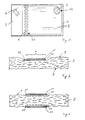
- optically variable elements 5 and 6 are applied to the surface as copy protection.
- these elements can contain holographic relief structures, diffraction structures, interference layers, liquid crystal polymers and other optically acting surfaces.
- the element 5 represents a reflection hologram with, for example, a circular base area.
- the element 6 is applied to the surface in the form of a band and extends over the entire width of the banknote.
- this element preferably contains a repeating, continuous diffraction grating.
- the note has smoothed areas 15 and 16 according to the invention.
- the area boundaries are indicated by broken lines.
- the optically variable elements 5 and 6 are applied within the smoothed surface areas 15 and 16.
- the size of the areas is selected so that the elements can be safely placed within these areas within the scope of the manufacturing tolerances, but it is also possible to give the areas any outline shape and size according to the design requirements.
- the smoothed areas can be produced by local satinizing, brushing or coating.
- FIG. 2 shows an enlargement of a section through the banknote 1 in the area of the element 6.
- a local surface has been used to produce a smooth surface in the area 15 as well as in the area 16 (not shown). Outside of these areas 15 and 16, the bank note has the original surface roughness 9. Due to the high surface quality in the smoothed areas, the range of variation for the application and the embodiments of the optically variable elements 5 and 6 increases.
- the element 6 can be applied by the embossing process.
- An adhesive layer 10 is first applied in the smoothed surface area. Due to the surface quality, the layer thickness can now be optimized for the usability of the note in terms of flexibility, security against counterfeiting and the effect of the element.
- a diffraction grating is then embossed into the adhesive layer 10.
- the embossed surface is then provided with a thin metal reflection layer and coated with a protective lacquer 11; the embossed lattice structures and the metal layer are not shown in FIG. 2 because of their microscopic size.
- element 6 is applied using the transfer method.
- the element is available in a prefabricated form on a transfer belt.
- the prefabrication on the belt makes it possible to insert any optically effective layers into the layer structure; special reference is made to reflective metal layers, interference layers, diffraction gratings and holograms.
- the smoothing of the paper substrate 8 in the area 15 of the application makes it possible to transfer transfer elements to paper in good quality despite their small thickness and their low internal strength.
- a layer structure similar to that of the embossing process results; it consists of an adhesive layer 10, optically acting layers above it and one or more lacquer layers 11.
- satinizing When satinizing, a high pressure is exerted on the paper in the areas to be smoothed, as a result of which the paper fibers are irreversibly pressed against one another and the surface roughness is reduced. In addition to smoothing, satinizing also compresses the paper substrate 8, as a result of which a depression is formed in the paper. This recess has the advantage that an optical element located therein is protected from touching and damage in any subsequent processing steps, such as when printing on the paper.
- Fig. 3 also shows an enlarged section through the bank note 14, wherein in this embodiment the surface on the front and back was smoothed by brushing on both sides.
- a coating slip is applied to the paper substrate in the surface areas 20 and 21.
- the coated paper was additionally drawn through a smoothing unit with highly polished smoothing cylinders, as a result of which the coating slip was pressed into the paper.
- the result is a banknote paper with two opposed smooth surface areas that do not or only slightly protrude from the paper surface.
- the coating colors known from paper production can be used as a coating slip. Both embossing and transfer elements can be applied to the smoothed areas in the ways already described.
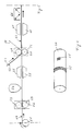
- Fig. 4 shows a calendering cylinder 30, as it can be used in the smoothing station for local smoothing of paper.
- the paper runs between two cylinders pressed against each other.
- one or both cylinders are replaced by the calendering cylinder 30 shown in FIG. 4 in such a smoothing station.
- This cylinder has raised areas 31 and 32 in the hologram areas. The step height between raised and recessed areas is preferably in the range of one millimeter and less.
- the surface 31 extends only over a small part of the circumferential surface and is suitable for producing isolated, smoothed areas in which, for example, the element 5 can be used.
- the surface 32 extends over the entire circumference and creates endless strip-shaped zones on the paper web which are particularly suitable for the application of endless elements 6.
- the calender is preferably designed in such a way that the raised areas on the calendering cylinder stand out from the remaining areas only in the order of a fraction of a millimeter, preferably 5-50 micrometers.
- the distance between the two calendering cylinders is adjusted so that, on the one hand, the paper is strongly smoothed at high pressure in the hologram area, but the paper is only compressed so much in the remaining area that no waves and distortions occur. In this way, the ripple is avoided and at the same time the roughness required for the steel engraving is obtained.
- the pressure for smoothing the paper is typically in the range of 100 - 1,000 kp per 1 cm contact line.
- Procedures known from coating technology can also be applied to the local coating of the paper surface, for example one can fall back on multi-level coating with pre-coating and finishing coating or on calendering coating with the help of coating calenders.
- a method derived from cast coating is particularly advantageous, in which case a coating slip is first applied locally to the paper surface and then dried in a smoothing unit with a heated, highly polished calendering cylinder and provided with a mirror-smooth surface.
- the production chain contains stations for preparing the paper surface, for applying and for checking transfer holograms. All machines are designed as reel machines and can be located somewhere between paper making and printing. This boundary condition is indicated in FIG. 5 by the dashed dividing lines provided at the beginning and at the end of the production chain.
- the manufacturing chain is inserted before the so-called cross cutter during paper production, i. H. the paper roll 51 comes from the web cutter of the paper machine, in which the wide web coming from the paper machine is broken down into narrower individual webs; the station 66 follows the cross cutter, which divides the paper web into individual sheets.
- the security web 50 is fed continuously from the stations.
- the paper can be drawn off from a supply roll 51 or can also be fed directly from paper-producing machines.
- the paper runs into a calender 52, which consists of two opposing calendering cylinders 53.
- the cylinders have raised areas 32 which, as shown in FIG. 4, extend over the entire circumference of the cylinders. The raised areas are repeated across the width of the cylinder in accordance with the number of panels available.
- the paper is fed to an application station 54, which applies an adhesion promoter to the smoothed strip or strips.
- the paper web runs into a drying device 55, here the adhesion promoter is dried by means of heat.
- IR, UV or electron beam dryer As an alternative to drying by means of heat, other methods can also be used, for example IR, UV or electron beam dryer.
- an endless hologram is applied to the smoothed strip or strips.
- the transfer belt 57 with the prefabricated holograms is pulled off a supply roll (not shown) and brought together with the paper web.
- Positioning devices also not shown, ensure that the transfer belt comes to lie in register with the smoothed strips.
- the two rollers 60 and 61 of the transfer station are heated and press the transfer belt and paper web against one another. Under the influence of pressure and heat, the holographic layer structure 62 detaches from the transfer belt and connects to the paper web 50.
- the empty transfer belt 58 is then pulled off the paper web and disposed of on a winding device (not shown).
- the paper web 50 provided with the endless hologram then runs to a second drying device 65 in which the transfer adhesive is cured. Depending on the adhesive used, various drying methods can also be used here.
- the paper web then runs to station 64, in which a quality check is carried out on the endless hologram.
- the diffraction efficiency and the position of the hologram on the paper can be checked by scanning with a light beam.
- the quality-checked paper web is now ready for printing. It can now either be wound up and stored on the winding device 65, as shown, or be introduced directly into a printing press known to the person skilled in the art.
- embossing stations can also be used in this production chain instead of a transfer station for applying transfer holograms for the production of embossed holograms or machines for applying other types of elements. It is also possible to feed the paper web to other machines instead of the winding device, such as printing units for printing processes or sheet cutters for disassembly into sheet sorting devices, etc.
- the production chain described consists of the higher-level process steps paper production, element application and printing.
- this sequence which is only made possible by the invention, can be integrated into the production of securities with particularly great advantages with regard to production speed, production process, etc.
- all the steps necessary for the application of the elements can be carried out in the paper mill, the paper can then be processed like any other security.
Abstract
Description
Die Erfindung betrifft einen Datenträger aus Papier, insbesondere ein Wertpapier, eine Banknote oder dergleichen mit einem auf der Oberfläche aufgebrachten optisch variablen Sicherheitselement, wie z. B. ein Beugungsgitter, Hologramm, Interferenzelement, Flüssigkristallpolymer oder dergleichen mit einem zusätzlich in einem Druckverfahren, insbesondere einem Stahltiefdruckverfahren, aufgebrachten Druckbild sowie ein Verfahren und eine Vorrichtung zur Herstellung desselben.The invention relates to a data carrier made of paper, in particular a security, a bank note or the like with an optically variable security element applied to the surface, such as. B. a diffraction grating, hologram, interference element, liquid crystal polymer or the like with an additionally applied in a printing process, in particular a steel intaglio printing process, as well as a method and an apparatus for producing the same.
Zum Schutz gegen Nachahmung mit Farbkopierern werden Wertpapiere zunehmend mit optisch variablen Sicherheitselementen, insbesondere Hologrammen, ausgestattet. Der Fälschungsschutz beruht auf der ungenügenden Wiedergabe der optischen Eigenschaften der Elemente durch die Kopiergeräte.To protect against imitation with color copiers, securities are increasingly being equipped with optically variable security elements, in particular holograms. The counterfeit protection is based on the insufficient reproduction of the optical properties of the elements by the copiers.
Zur Aufbringung von optisch variablen Elementen (OVD), insbesondere von Hologrammen auf Datenträger, sind verschiedene Verfahren bekannt, sie lassen sich in die drei Kategorien Kleben, Transferdruck und Prägen einteilen.Various methods are known for applying optically variable elements (OVD), in particular holograms to data carriers, and they can be divided into three categories: gluing, transfer printing and embossing.
Beim Kleben werden Haftetiketten, die sich zunächst vorgestanzt auf Silikonpapier befinden, maschinell auf das Papiersubstrat übertragen. Die Haftetiketten weisen einen Schichtaufbau auf, der sich aus einer Haftklebeschicht, einer selbsttragenden Folie mit einer optisch aktiven Schicht über beispielsweise einem Beugungsgitter und einer darüberliegenden Schutzschicht zusammensetzt. Die Dicke eines Haftetiketts liegt typischerweise in der Größe von 50 Mikrometer, wobei der wesentliche Anteil der Dicke auf das Folienmaterial entfällt.When gluing, adhesive labels, which are initially pre-punched on silicone paper, are transferred mechanically to the paper substrate. The adhesive labels have a layer structure, which is composed of a pressure-sensitive adhesive layer, a self-supporting film with an optically active layer over, for example, a diffraction grating and an overlying protective layer. The thickness of an adhesive label is typically around 50 micrometers, the major part of the thickness being attributable to the film material.
Beim Transferdruck, auch Heißprägen genannt, wird das optisch variable Element auf einem Transferband vorgefertigt und in einem nachfolgenden Arbeitsschritt auf das Substrat übertragen. Der auf das Papier übertragene Aufbau besitzt typischerweise eine Dicke im Bereich von wenigen Mikrometer. Im Fall von Hologrammen besteht der übliche Schichtaufbau des Elements aus einer Heißklebeschicht, einer Lackschicht mit Prägung, einer Aluminium-Aufdampfschicht und einer transparenten abdeckenden Schutzschicht. Dieser Schichtaufbau befindet sich zunächst auf der Transferfolie, wobei er mit einer Release-schicht (z. B. einer Wachsschicht) auf der Folie "befestigt" ist. Zum Transfer wird das Band mit der Heißklebeschicht auf das Substrat aufgelegt, durch Anpressen eines geheizten Stempels wird die Heißklebeschicht aktiviert, so daß sich das Element mit dem Substrat verbindet. Gleichzeitig schmilzt die Trennschicht, wodurch sich das Hologramm vom Transferband löst. Das Transferprinzip ist heute das am häufigsten angewandte Verfahren und wird insbesondere zum Aufbringen von Hologrammen auf Kunststoff-Kreditkarten verwendet.In transfer printing, also called hot stamping, the optically variable element is prefabricated on a transfer belt and transferred to the substrate in a subsequent step. The one transferred to the paper Structure typically has a thickness in the range of a few micrometers. In the case of holograms, the usual layer structure of the element consists of a hot glue layer, a lacquer layer with embossing, an aluminum vapor deposition layer and a transparent protective covering layer. This layer structure is initially on the transfer film, with it being "attached" to the film with a release layer (eg a wax layer). For the transfer, the tape with the hot-melt adhesive layer is placed on the substrate; the hot-melt adhesive layer is activated by pressing on a heated stamp, so that the element connects to the substrate. At the same time, the separating layer melts, causing the hologram to detach from the transfer belt. The transfer principle is the most frequently used method today and is used in particular to apply holograms to plastic credit cards.
Das Prägeverfahren eignet sich vor allem für Beugungselemente, wie Hologramme und optische Gitter. Hierbei wird auf ein Substrat eine Schicht aus einem aushärtbaren Lack aufgetragen, der vorzugsweise mit einer extrem dünnen und reflektierenden Metalloberfläche versehen ist. Mit einem Prägestempel wird in die Lackschicht die beugungsoptische Reliefstruktur eingeprägt, nach dem Aushärten des Lacks wird die Struktur mit einem Schutzlack abgedeckt Das fertige Element weist einen Schichtaufbau aus, der aus den aufeinanderfolgenden Schichten von Lack mit Metallschicht und Reliefstruktur sowie der Schutzlackschicht besteht.The embossing process is particularly suitable for diffraction elements such as holograms and optical gratings. Here, a layer of a curable lacquer is applied to a substrate, which is preferably provided with an extremely thin and reflective metal surface. The diffractive relief structure is embossed into the lacquer layer with an embossing stamp.After the lacquer has hardened, the structure is covered with a protective lacquer.The finished element has a layer structure consisting of the successive layers of lacquer with a metal layer and relief structure and the protective lacquer layer.
Jedes der Verfahren und der daraus resultierenden Produkte hat seine speziellen Vor- und Nachteile. Klebeetiketten beispielsweise sind technisch einfach herstellbar und problemlos auf die vorgesehenen Substrate übertragbar. Extrem nachteilig für eine Anwendung auf dem Wertpapiersektor ist bei Klebeetiketten allerdings die Möglichkeit, die Elemente als Ganzes vom Substrat zu lösen und auf gefälschte Produkte zu übertragen. Aus diesem Grund werden für Wertpapieranwendungen die Transfer-und Prägeelemente bevorzugt.Each of the processes and the resulting products has its own advantages and disadvantages. Adhesive labels, for example, are technically simple to produce and can be transferred to the intended substrates without any problems. Adhesive labels, however, are extremely disadvantageous for use in the securities sector the possibility of detaching the elements as a whole from the substrate and transferring them to counterfeit products. For this reason, the transfer and embossing elements are preferred for security applications.
Die Transfer- und Prägeelemente genügen weitgehend dem auf dem Wertpapiersektor geforderten Bedürfnissen an Fälschungssicherheit, jedoch stellen sich bei der Fertigung von Wertpapieren mit diesen Elementen eine Reihe von fertigungstechnischen Problemen. Im besonderen Maße sind die beiden folgenden Randbedingungen zu beachten.The transfer and embossing elements largely meet the counterfeit protection requirements demanded in the securities sector, but there are a number of production-related problems in the production of securities with these elements. The following two boundary conditions must be observed in particular.
Als erster Punkt ist zu berücksichtigen, daß Wertpapiere üblicherweise ein sicherheitstechnisch hochwertiges Druckbild besitzen; diese Druckbilder werden in den meisten Fällen mit Hilfe von Stahltiefdruckverfahren aufgebracht. Stahltiefdruck und verwandte Verfahren erfordern, damit sich die Druckfarben gut mit dem Substrat verbinden, eine relativ hohe Oberflächenrauhigkeit des Substrats. Rauhe Oberflächen jedoch sind für die Aufbringung von optischen Elementen ungeeignet.The first point to be considered is that securities usually have a high-quality security image; in most cases, these printed images are applied using steel gravure printing processes. Gravure printing and related processes require a relatively high surface roughness of the substrate so that the printing inks bond well to the substrate. Rough surfaces, however, are unsuitable for the application of optical elements.
Zum zweiten ist zu beachten, daß das Wertpapier beim Stahltiefdruck auf seiner ganzen Fläche einer sehr hohen Druckbelastung ausgesetzt wird. Eventuell vor dem Druck aufgebrachte optische Elemente werden hierdurch gewöhnlich in ihrer optischen Wirkung herabgesetzt und können durch die sich vom Papieruntergrund durchprägende Papierrauhigkeit sogar beschädigt oder völlig zerstört werden.Secondly, it should be noted that in steel intaglio printing, the entire surface of the security is exposed to a very high pressure load. Any optical elements that may have been applied prior to printing are hereby usually reduced in their optical effect and can even be damaged or completely destroyed by the paper roughness which is evident from the paper substrate.
Bei der Herstellung von mit optisch variablen Elemente ausgestatteten Wertpapieren stattete man aufgrund dieser Problematik deshalb das Wertpapier entweder zuerst mit dem Druckbild aus und brachte das OVD in einen der darauffolgenden Verfahrensschritte auf oder man zerlegte die OVD-Aufbringung in Einzelscshritte, wobei die durch das Stahltiefdruckverfahren nicht gefährdeten Maßnahmen vor dem Bedrucken, die anderen aber ebenfalls erst nach dem Druckvorgang vorgesehen wurden. Bei dieser Vorgehensweise nahm man bewußt in Kauf, daß durch die direkte Verkopplung mit dem Druckvorgang einerseits keine auftragsneutrale Vorfertigung von unbedruckten OVD-Wertpapieren möglich war (keine Produktion auf Halde) und andererseits die Aufbringung der OVD's pro Drucklinie dafür geeignete Maschinen (Transfermaschinen etc.) benötigt. Die pro Drucklinie benötigten "OVD-Maschinen" erhöhen nicht nur die Kosten und den Raumbedarf für den Maschinenpark, sondern bilden aufgrund der abweichenden Produktionskapazität am Ende der Drucklinie jeweils einen Engpaß, der mit erhöhtem Aufwand auszugleichen ist.In the production of securities equipped with optically variable elements, the problem was either that the security was first equipped with the printed image and the OVD was applied in one of the subsequent process steps, or the OVD application was broken down into individual steps, whereby the The steel gravure printing process did not endanger the measures before printing, but the others were also only provided after the printing process. With this approach, it was consciously accepted that, due to the direct coupling with the printing process, on the one hand no order-neutral prefabrication of unprinted OVD securities was possible (no stockpile production) and on the other hand the application of OVDs per printing line suitable machines (transfer machines etc.) needed. The "OVD machines" required per print line not only increase the costs and the space required for the machine park, but due to the different production capacity at the end of the print line each create a bottleneck, which can be compensated for with increased effort.
Aus der EP-OS 338 378 ist ein derartiges System zur Fertigung von Papierprodukten bekannt, die sowohl ein Druckbild wie ein optisches Beugungselement aufweisen. In einem kontinuierlichen Prozeß wird das Papier zunächst in bekannten Druckwerken bedruckt. Anschließend wird analog zum beschriebenen Prägeverfahren in einem Arbeitsgang ein strahlungshärtbarer Lack aufgetragen und mit einer Beugungsstruktur versehen. In nachfolgenden Arbeitsgängen wird die Beugungsstruktur mit einer reflektierenden Metallschicht bedampft und mit einem Schutzlack versehen.From EP-OS 338 378 such a system for the production of paper products is known which have both a printed image and an optical diffraction element. In a continuous process, the paper is first printed in known printing units. A radiation-curable lacquer is then applied in a single operation, analogous to the embossing process described, and provided with a diffraction structure. In subsequent operations, the diffraction structure is vapor-coated with a reflective metal layer and provided with a protective lacquer.
In anderen bekannten Systemen wird der Arbeitsgang der Hologrammaufbringung zweigeteilt. Im Anschluß an die Papierherstellung wird in einem ersten Teilschritt der Lack auf die Papieroberfläche aufgetragen. Nach dem Bedrucken des Papiers wird im nächsten Teilschritt das optische Gitter eingeprägt.In other known systems, the hologram application process is divided into two. Following the paper production, the varnish is applied to the paper surface in a first sub-step. After printing on the paper, the optical grid is embossed in the next step.
In der US-PS 4,420,515 ist eine Variante dieses zweiteiligen Verfahrens beschrieben. Auf ein Kunststoff-Transferband mit einer präparierten Oberfläche wird zunächst eine Metallschicht und eine darüberliegende Klebeschicht aufgebracht, diese beiden Schichten bilden den Unterbau des zukünftigen Sicherheitselements. Im ersten Teilschritt werden die beiden Schichten auf das Substrat laminiert, wobei unter der Wärme- und Druckeinwirkung beim Laminiervorgang der Unterbau des Elements die Oberflächenqualität des Transferbandes annimmt. Im zweiten Teilschritt werden ein Druckbild und eine optisch wirkende Reliefstruktur auf das Substrat aufgebracht.A variant of this two-part process is described in US Pat. No. 4,420,515. A metal layer and an overlying layer are first placed on a plastic transfer belt with a prepared surface Adhesive layer applied, these two layers form the substructure of the future security element. In the first sub-step, the two layers are laminated to the substrate, the substructure of the element assuming the surface quality of the transfer belt under the action of heat and pressure during the lamination process. In the second sub-step, a printed image and an optically acting relief structure are applied to the substrate.
Die erzwungene Reihenfolge von Bedrucken und Aufbringen der optisch wirksamen Schichten bzw. das Aufbringen der optisch wirksamen Strukturen führt, wie bereits angedeutet, zu einer Reihe von schwerwiegenden Nachteilen.As already indicated, the forced sequence of printing and application of the optically active layers or the application of the optically active structures leads to a number of serious disadvantages.
Ein Nachteil der bekannten Verfahren besteht in den stark differierenden Fertigungsgeschwindigkeiten von Druckmaschinen und den Vorrichtungen, die die optischen Elemente aufbringen. Vergleicht man hierbei Maschinen des gleichen Typs, wie beispielsweise Bogen-Druckmaschinen und Bogen-Hologramm-Maschinen, dann wird auffällig, daß Hologramm-Maschinen eine um einen Faktor 4 niedrigere Verarbeitungsgeschwindigkeit besitzen. Die geringere Arbeitsgeschwindigkeit der Hologramm-Maschinen hat prinzipielle verfahrenstechnische Gründe, so ist beispielsweise das Prägen von mikrometerfeinen Strukturen ein sehr sorgfältig durchzuführender und damit zeitaufwendiger Verfahrensschritt. In einer Fertigungskette aus Druckmaschinen und Hologramm-Maschinen stellt somit die Hologramm-Aufbringung einen die Fertigungsgeschwindigkeit begrenzenden Engpaß dar.A disadvantage of the known methods is the greatly differing production speeds of printing presses and the devices which apply the optical elements. If you compare machines of the same type, such as sheet-fed printing machines and sheet-hologram machines, it becomes apparent that hologram machines have a processing speed which is four times lower. The lower working speed of the hologram machines has fundamental procedural reasons, for example the embossing of micrometer-fine structures is a very careful and therefore time-consuming process step. In a production chain consisting of printing machines and hologram machines, the hologram application thus represents a bottleneck that limits the production speed.
Die erzwungene Reihenfolge in der Fertigung wirkt sich besonders nachteilig im Fall der Wertpapierfertigung aus. Stahltiefdruckmaschinen sind verfahrensbedingt fast ausschließlich Bogen-Maschinen, weshalb auch die nachfolgende Hologrammaufbringung auf Bogen-Maschinen zu erfolgen hat. Bekanntlich weisen aber gerade Bogen-Maschinen wegen der Handhabung des Bogenmaterials prinzipiell eine niedrige Verarbeitungsgeschwindigkeit auf, diese Eigenschaft trifft auch auf Hologramm-Maschinen zu. Da wegen der bereits geschnittenen Bögen im Rahmen der Hologramm-Fertigung auch nicht auf die deutlich schneller arbeitenden Rollen-Maschinen ausgewichen werden kann, ergibt sich als Folge, daß unter allen möglichen Gestaltungen einer Fertigungskette für Wertpapiere die bekannten Verfahren nur solche Varianten mit der minimal möglichen Verarbeitungsgeschwindigkeit zulassen.The forced order in production has a particularly disadvantageous effect in the case of securities production. Steel intaglio printing machines are almost exclusively sheet-fed machines due to the process, which is why the subsequent hologram application must also be carried out on sheet-fed machines. As is well known, however, bow machines in particular Because of the handling of the sheet material, there is in principle a low processing speed; this property also applies to hologram machines. Since it is not possible to switch to the much faster working reel machines because of the already cut sheets in the hologram production, the result is that under all possible designs of a production chain for securities, the known methods only use those variants with the minimum possible Allow processing speed.
Ein weiterer Nachteil der bekannten Verfahren ist ihre schwierige Eingliederung in den Organisationsablauf von Wertpapierdruckereien. Aus sicherheitstechnischen Gründen ist es bei der Wertpapierherstellung praktisch unumgänglich, daß der Druckvorgang, insbesondere das Drucken der Seriennummer, den letzten Verarbeitungsvorgang vor der Auslieferung der Wertpapiere darstellt. In Wertpapierdruckereien ist es deshalb feste Gepflogenheit, Papier mit den zugehörigen Sicherheitsmerkmalen wie Wasserzeichen, Sicherheitsfaden und eventuellen optischen Elementen vorzufertigen und anschließend zu bedrucken. Die Beibehaltung dieser Fertigungsfolge ist dabei bei den bekannten Verfahren ebenfalls nicht möglich.Another disadvantage of the known methods is their difficult integration into the organizational process of security printing houses. For security reasons, it is practically inevitable in the production of securities that the printing process, in particular the printing of the serial number, represents the last processing process before the delivery of the securities. It is therefore customary in securities printing houses to prefabricate paper with the associated security features such as watermarks, security thread and any optical elements and then to print on it. It is also not possible to maintain this production sequence in the known methods.
Ein weiterer Nachteil der bekannten Verfahren ist der Zugriff auf Technologien, die im Bereich der Papierherstellung und Drucktechnik unüblich sind. Unter diesem Aspekt stellt beispielsweise das Vakuumbedampfen der geprägten Elemente (siehe EP-OS 338 378) oder eines präparierten Transferbandes (siehe US-PS 4,420,515) eine Fremdtechnologie dar, die sich derzeit in Papier- und Druckbetriebe nicht integrieren läßt. Gründe hierfür sind die schon erwähnten unterschiedlichen Verarbeitungsgeschwindigkeiten der verschiedenen Maschinen, die derzeit noch hohe Anfälligkeit der Fremdtechnologien, die Notwendigkeit von Spezialisten usw., so daß auch bereits aus diesen Gründen ein reibungsloser Betrieb einer Fertigungskette nicht gewährleistet ist.Another disadvantage of the known methods is the access to technologies that are unusual in the field of paper production and printing technology. From this point of view, vacuum deposition of the embossed elements (see EP-OS 338 378) or a prepared transfer belt (see US Pat. No. 4,420,515) is a third-party technology that cannot currently be integrated in paper and printing companies. The reasons for this are the already mentioned different processing speeds of the various machines, the high vulnerability of third-party technologies, the necessity by specialists, etc., so that smooth operation of a production chain cannot be guaranteed for these reasons alone.
Ausgehend von diesem Stand der Technik und seinen Nachteilen stellt sich die Aufgabe, eine Wertpapierform und ein Verfahren zu seiner Herstellung zu finden, das es gestattet,
- die für das Druckbild und das optische Element notwendigen Fertigungsschritte variabel in ihrer Reihenfolge anzuordnen,
- die verschiedenen Fertigungsmaschinen nach ihrer Fertigungskapazität und Verarbeitungsgeschwindigkeit auszuwählen und zusammenzustellen und
- ohne Fremdtechnologie und ohne Störung des Organisationsablaufs bei Papierherstellern und in Druckbetrieben, insbesondere in Wertpapierdruckereien in der gewohnten Umgebung zu fertigen.
- to arrange the manufacturing steps necessary for the printed image and the optical element variably in their order,
- select and assemble the various manufacturing machines according to their manufacturing capacity and processing speed and
- To manufacture without third-party technology and without disrupting the organizational process at paper manufacturers and in printing companies, especially in securities printing plants in the familiar environment.
Die Aufgabe wird durch die im Kennzeichen des Hauptanspruchs genannten Merkmale gelöst. Vorteilhafte Weiterbildungen sind den Unteransprüchen zu entnehmen.The object is achieved by the features mentioned in the characterizing part of the main claim. Advantageous further developments can be found in the subclaims.
Der Erfindung liegt die bisher vernachlässigte Erkenntnis zugrunde, daß optisch variable Elemente und Papier zwei Materialien mit höchst unterschiedlichen Eigenschaften sind und daß entsprechend der vorgesehenen Funktion auch extrem verschiedene Anforderungen an die beiden Materialien gestellt werden. Papier, insbesondere Wertpapier, hat neben anderen Eigenschaften eine gewisse "Griffigkeit" aufzuweisen, weiter muß das Papier Druckfarben gut annehmen und binden können. Diese Eigenschaften erreicht man durch Wahl spezieller Papierarten, vorzugsweise Hadernpapier sowie durch Einstellung einer vorbestimmten Oberflächenrauhigkeit und -struktur. Optisch variable Elemente haben dagegen optische Eigenschaften mit möglichst hohem Wirkungsgrad aufzuweisen. Die physikalischen Gesetze erfordern hierfür aber in erster Linie Oberflächenstrukturen, die sich durch eine sehr glatte und ebene Oberfläche auszeichnen.The invention is based on the previously neglected finding that optically variable elements and paper are two materials with very different properties and that, depending on the intended function, extremely different requirements are placed on the two materials. Paper, in particular security paper, has, among other properties, a certain "grip", and the paper must also be able to accept and bind printing inks well. These properties are achieved by choosing special types of paper, preferably rag paper, and by setting a predetermined one Surface roughness and structure. In contrast, optically variable elements have to have optical properties with the highest possible efficiency. However, the physical laws primarily require surface structures that are characterized by a very smooth and even surface.
Beim Aufbringen der optischen Elemente auf Papier wird deshalb ein Ausgleich zwischen den unterschiedlichen Oberflächenqualitäten notwendig. Gemäß dem derzeitigen Stand der Technik erfolgte der Ausgleich bisher ausschließlich dadurch, daß der Aufbau und/oder die Aufbringungsverfahren der optischen Elemente der Rauhigkeit des Substrats angepaßt wurden. Die Verlagerung des Oberflächenausgleichs in den Bereich der optischen Elemente wurde auch durch den Umstand stark begünstigt, daß insbesondere im Wertpapierbereich die Papiereigenschaften innerhalb enger Toleranzen festgelegt sind und somit im ganzen Fertigungsprozeß als nicht variable Größen verstanden wurden.When applying the optical elements to paper, it is therefore necessary to balance the different surface qualities. According to the current state of the art, the compensation has hitherto been achieved exclusively by adapting the structure and / or the application method of the optical elements to the roughness of the substrate. The shifting of the surface compensation in the area of the optical elements was also greatly favored by the fact that, particularly in the area of securities, the paper properties are defined within narrow tolerances and were therefore understood as non-variable variables in the entire manufacturing process.
Im Gegensatz zur bisherigen Vorgehensweise besteht der Kern der Erfindung darin, in einem ersten Schritt mit Verfahren, die bei Papierherstellern und in Druckbetrieben geläufig sind, das Papier in dem für das optisch variable Element bestimmten Flächenbereich das Papier durch lokale Glättung an die Ebenheitsforderung der optischen Elemente anzupassen. Geglättet wird dabei im wesentlichen nur der Flächenbereich, der vom vorgesehenen Element abgedeckt wird. Der Restbereich wird bei der Glättung soweit wie möglich unverändert belassen, so daß dort die für die Druckverfahren benötigte Oberflächenqualität erhalten bleibt. Das optische Element wird in einem nachfolgenden Arbeitsschritt, vorzugsweise bereits vor dem Bedrucken, in den geglätteten Bereich aufgebracht.In contrast to the previous procedure, the essence of the invention is, in a first step using methods that are familiar to paper manufacturers and in printing companies, the paper in the area intended for the optically variable element, the paper by local smoothing to the flatness requirement of the optical elements adapt. Essentially, only the surface area that is covered by the element provided is smoothed. The remaining area is left as unchanged as possible during smoothing, so that the surface quality required for the printing process is maintained there. The optical element is applied to the smoothed area in a subsequent work step, preferably before printing.
Durch diese überraschend einfache Maßnahme schafft man auf einen Datenträger lokal begrenzte und auf den jeweiligen Bestimmungszweck optimal angepaßte Randbedingungen, welche auch die Erfüllung sehr unterschiedlicher Anforderungen sicherstellt.This surprisingly simple measure creates boundary conditions locally limited to a data carrier and optimally adapted to the respective intended purpose, which also ensures that very different requirements are met.
Zum Glätten und Verfestigen der Papieroberfläche sind aus der Druck- und Papiertechnik verschiedene Verfahren bekannt, die sich im wesentlichen in die Kategorien Satinieren, Streichen und Beschichten einteilen lassen. Diese Verfahren können in modifizierter Form auch für die lokale Glättung der Oberfläche verwendet werden.Various methods are known from printing and paper technology for smoothing and solidifying the paper surface, which can essentially be divided into the categories of satin finishing, brushing and coating. These methods can also be used in a modified form for the local smoothing of the surface.
Zum Satinieren führt man das Papier in Rollen- oder Bogenform in ein Glättwerk ein, das beispielsweise aus zwei gegenüberliegenden Zylindern besteht. Um eine lokal begrenzte Glättung zu erreichen, sind eine oder beide Zylinder des Glättwerks in dem Bereich, in dem die Aufbringung des Elements erfolgen soll, erhaben gestaltet, so daß das Papier vor allem in diesem Bereich zusammengedrückt und geglättet wird. Dabei wird ein Druck in der Größe von 100 - 1.000 kp/cm Berührungslinienlänge ausgeübt. Den Erfordernissen entsprechend werden die Hologrammbereiche entweder nur bei einem oder bei beiden Zylindern erhaben gestaltet.For satinizing, the paper in roll or sheet form is introduced into a smoothing unit which, for example, consists of two opposing cylinders. In order to achieve locally limited smoothing, one or both cylinders of the smoothing unit are raised in the area in which the element is to be applied, so that the paper is compressed and smoothed especially in this area. A pressure of 100-1,000 kp / cm contact line length is exerted. Depending on the requirements, the hologram areas are either raised on only one or on both cylinders.
Beim Streichen und verwandten Verfahren wie Gießen, Gußstreichen usw. wird auf die Papieroberfläche ein Strich bzw. ein Guß aufgetragen. Um ein lokal begrenztes Streichen zu erhalten, werden an die Erfindung angepaßte Auftragwerke notwendig. Für den streifenweisen Auftrag eignen sich beispielsweise Düsenauftragwerke mit seitlich begrenzten Schlitzdüsen, während für beliebig geformte Flecken Gravurwalz- oder Rundsiebwerke vorzuziehen sind. Streich- und Gußmassen bestehen im wesentlichen aus mineralischen Pigmenten und Bindemitteln, die die Pigmente zusammenhalten und im Rohpapier verankern. Die Partikelgröße liegt typisch im Bereich von Mikrometern, weshalb gestrichene oder gegossene Papiere eine geglättete Oberfläche aufweisen.When painting and related processes such as casting, cast coating, etc., a line or cast is applied to the paper surface. In order to obtain locally limited painting, application works adapted to the invention are necessary. For the strip-wise application, for example, nozzle applicators with laterally limited slot nozzles are suitable, while for randomly shaped spots, gravure roller or rotary screen machines are preferred. Coating and casting compounds essentially consist of mineral pigments and binders that hold the pigments together and anchor them in the base paper. The Particle size is typically in the range of micrometers, which is why coated or cast papers have a smooth surface.
Beim Beschichten wird ähnlich wie beim Streichen auf die Papieroberfläche eine Ausgleichsmasse aufgetragen, die zumindest zum Teil aus Kunststoffmaterialien besteht. Wie beim Streichen eignen sich zum Auftrag der Ausgleichsmasse Düsenauftragwerke, Gravurwalzwerke oder Rundsiebwerke.When coating, a leveling compound is applied to the paper surface, similar to painting, which consists at least partially of plastic materials. As with spreading, the application of the leveling compound is based on nozzle applicators, gravure rolling mills or circular screens.
Als Glättwerke können sowohl Rollen- wie Bogenmaschinen verwendet werden. Mit kontinuierlich glättenden Rollenmaschinen lassen sich auf Papierbahnen eine oder mehrere streifenförmige Zonen erstellen, die über die gesamte Bahnlänge eine geglättete Oberfläche aufweisen. Diese streifenförmigen Zonen eignen sich insbesondere zur späteren Aufbringung von Endloselementen, die in Band- oder Fadenform vorliegen. Besonders vorteilhaft ist es, die Endloselemente ebenfalls mit Rollenmaschinen aufzubringen.Both reel and sheet machines can be used as smoothing units. With continuously smoothing reel machines, one or more strip-shaped zones can be created on paper webs that have a smooth surface over the entire web length. These strip-shaped zones are particularly suitable for the later application of endless elements which are in the form of strips or threads. It is particularly advantageous to also apply the endless elements with roller machines.
Um für die Hologrammaufbringung hinreichend glattes Papier zu erzeugen, ist sehr hoher Druck erforderlich. Je nach Papiersorte oder Form des geglätteten Bereichs kann es dabei vorkommen, daß sich das Papier wellt und zum Drucken nicht mehr eignet. In diesem Fall benutzt man ein Glättwerk, in dem die Bereiche, an denen die Hologrammaufbringung erfolgen soll, gegenüber dem Restbereich nur um 100stel Millimeter (vorzugsweise 5 - 50 Mikrometer) erhaben sind. Dadurch wird erreicht, daß einerseits im Hologrammbereich das Papier bei hohem Druck stark geglättet wird, während im übrigen Bereich das Papier nur so viel zusammengedrückt wird, daß keine Wellen und Verzüge auftreten, aber die für den Stahlstich erforderliche Rauhigkeit erhalten bleibt.Very high pressure is required to produce sufficiently smooth paper for the hologram application. Depending on the type of paper or the shape of the smoothed area, the paper may curl and may no longer be suitable for printing. In this case, a smoothing mechanism is used in which the areas where the hologram is to be applied are only raised by 100ths of a millimeter (preferably 5-50 microns) compared to the rest of the area. This ensures that, on the one hand, the paper is strongly smoothed at high pressure in the hologram area, while in the remaining area the paper is only compressed so much that no waves and distortions occur, but the roughness required for the steel engraving is retained.
Die Glättstation läßt sich innerhalb einer Fertigungskette praktisch an beliebiger Stelle vor der Hologrammaufbringung als Modul plazieren. Die kleinste Maschineneinheit besteht nur aus einer Abrolleinrichtung für die Papierbahn, einer Glättstation und einer Aufrolleinrichtung. Diese Einheit kann um geeignete Vorrichtungen zum Bedrucken des Papiers und zur Aufbringung von Hologrammen erweitert werden. Insbesondere können zwischen Glättstation und Aufrolleinrichtung folgende Einheiten eingefügt werden:
- 1. Einrichtungen zum Aufbringen eines Füllmittels, eines Haftvermittlers oder eines Klebemittels im Hologrammbereich.
- 2. Einrichtungen zum Trocknen für den Haftvermittler oder die Klebemittel mit Hilfe von Wärme, IR- oder UV-Strahlung oder Elektronenstrahlen.
- 3. Einrichtungen zum Aufbringen der optisch variablen Elemente, alternativ können hierfür eingesetzt werden
- Transfereinrichtungen für die Aufbringung von Heißpräge-Hologrammen oder anderen Heißpräge-Elementen,
- Einrichtungen zum Aufbringen von spiegelnden Flächen für nachträgliche Hologrammeinprägungen,
- Einrichtungen zum Auftragen von Lacken und ähnlichen Beschichtungen und zum Einprägen von optischen Beugungsstrukturen.
- 4. Einrichtungen zum Härten der geprägten Lacke, Beschichtungen oder Kleber mit Hilfe von Wärme oder Strahlung.
- 5. Einrichtungen zum Aufbringen von Schutzschichten mit Hilfe von Druck-, Beschichtungs- oder Kaschierverfahren.
- 6. Einrichtungen zur Qualitätsprüfung an den optisch variablen Elementen.
- 7. Einrichtungen zum Kennzeichnen oder Induvidualisieren der Bahnen, Nutzen oder Elemente.
- 8. Druckwerke für weitere Druckvorgänge.
- 1. Devices for applying a filler, an adhesion promoter or an adhesive in the hologram area.
- 2. Devices for drying the adhesion promoter or the adhesive with the aid of heat, IR or UV radiation or electron beams.
- 3. Devices for applying the optically variable elements, alternatively can be used for this
- Transfer devices for the application of hot stamping holograms or other hot stamping elements,
- Devices for applying reflective surfaces for subsequent hologram impressions,
- Devices for applying lacquers and similar coatings and for embossing optical diffraction structures.
- 4. Devices for curing the embossed paints, coatings or adhesives with the help of heat or radiation.
- 5. Devices for applying protective layers with the aid of printing, coating or laminating processes.
- 6. Equipment for quality control on the optically variable elements.
- 7. Facilities for labeling or individualizing the webs, benefits or elements.
- 8. Printing units for further printing processes.
Die gegebene Aufzählung ist weder vollständig noch legt sie die Reihenfolge der Maschinen zwingend fest, sie stellt vielmehr nur eine von vielen möglichen Alternativen dar. Der Maschinentyp und ihre Reihenfolge in der Fertigungskette können vom Fachmann anhand der Aufzählung je nach gewünschtem Fertigungsablauf und Elementtyp ausgewählt oder variiert werden. Ebenso ist es möglich, an geeigneten Stellen Aufrollvorrichtungen zum Zwischenspeichern oder weitere bekannte Maschinenelemente wie Rollenschneider, Bogenschneider oder Sortiervorrichtungen einzufügen.The given list is neither complete nor does it imply the order of the machines, it rather represents only one of many possible alternatives. The machine type and its order in the production chain can be selected or varied by the expert on the basis of the list according to the desired production process and element type will. It is also possible to insert roll-up devices for temporary storage or other known machine elements such as slitter reels, sheet cutters or sorting devices at suitable locations.
Trotz der verblüffend einfachen erfindungsgemäßen Maßnahmen bieten die erfindungsgemäße Datenträger und die Möglichkeiten zu seiner Herstellung zahlreiche Vorteile.Despite the astonishingly simple measures according to the invention, the data carriers according to the invention and the possibilities for their production offer numerous advantages.
Ein erster Vorteil ist die Qualitätsanhebung der mit optischen Elementen ausgestatteten Wertpapiere. Während früher der Schichtaufbau der Elemente auf die Papiereigenschaften abgestimmt werden mußte - man bedenke nur die dicken Klebeschichten zum Ausgleich der Oberflächenrauhigkeit -, so können jetzt im Rahmen der Erfindung die Elemente auf ihre eigentliche Funktion optimiert werden. Allein die Verwendung dünner Klebeschichten führt zu einer Reihe von Verbesserungen. Eine filmdünne Klebeschicht gewährleistet beispielsweise eine hohe Elastizität des Elements, wodurch es Belastungen, wie sie vor allem beim Wertpapierumlauf auftreten, leichter überleben kann. Weiter erhöht eine dünne Klebeschicht auch die Fälschungssicherheit, da ein Abspalten des Elements entlang der Klebeschicht erschwert oder unmöglich gemacht wird.A first advantage is the quality improvement of the securities equipped with optical elements. Whereas in the past the layer structure of the elements had to be matched to the paper properties - just consider the thick adhesive layers to compensate for the surface roughness - now the elements can be optimized for their actual function within the scope of the invention. The use of thin adhesive layers alone leads to a number of improvements. A film-thin adhesive layer ensures, for example, a high elasticity of the element, which makes it easier for it to survive stresses, such as those that occur when securities are in circulation. Furthermore, a thin adhesive layer also increases the security against counterfeiting, since it is difficult or impossible to split the element along the adhesive layer.
Eine weitere Qualitätsanhebung ergibt sich durch die Möglichkeit, von geprägten Hologrammen auf Transferelemente überzugehen. Transferelemente werden als Sicherheitselemente gegenüber geprägten Elementen bevorzugt aufgrund des einfacheren Aufbringverfahrens und des höheren optischen Wirkungsgrades. Da aber Transferelemente typischerweise nur eine Dicke im Bereich von wenigen Mikrometer aufweisen, wurden sie bisher kaum auf Papieroberflächen aufgetragen. Durch das erfindungsgemäße Glätten jedoch schafft man auf der Papieroberfläche aber auch die Voraussetzungen zum Aufbringen derartiger Transferelemente.A further increase in quality results from the possibility of changing from embossed holograms to transfer elements. Transfer elements are preferred as security elements over embossed elements due to the simpler application process and the higher optical efficiency. However, since transfer elements typically only have a thickness in the range of a few micrometers, they have hitherto hardly been applied to paper surfaces. However, the smoothing according to the invention also creates the conditions for applying such transfer elements on the paper surface.
Weitere Vorteile ergeben sich aus der Möglichkeit, im Rahmen der Erfindung die Hologramm-Aufbringung an besonders geeigneten Stellen in den Fertigungsablauf einzufügen. Die hieraus resultierende Erhöhung des Fertigungsdurchsatzes bzw. die Erhöhung der Fertigungskapazität zeigt sich am besten bei der Wertpapierherstellung. Die Arbeitsschritte Glätten und Hologrammaufbringung lassen sich jetzt wegen der Unabhängigkeit vom Druckprozeß noch im Rollenstadium des Papiers durchführen, die hohe Verarbeitungsgeschwindigkeit der Rollenmaschinen ermöglicht es, die Fertigungsengpässe zu umgehen, die bei der Verwendung von Bogen-Maschinen entstehen.Further advantages result from the possibility, within the scope of the invention, of inserting the hologram application in particularly suitable places in the production process. The resulting increase in manufacturing throughput or the increase in manufacturing capacity is best seen in securities manufacturing. The smoothing and hologram application steps can now be carried out at the roll stage of the paper because of the independence from the printing process, the high processing speed of the roll machines makes it possible to avoid the production bottlenecks that arise when using sheet-fed machines.
Aus der Unabhängigkeit von Druckprozeß und Hologrammaufbringung ergibt sich als weiterer Vorteil, daß der in den Wertpapierdruckereien übliche Verfahrensablauf eingehalten werden kann. So kann das Papier mit all seinen Sicherheitselementen wie Wasserzeichen, Sicherheitsfaden, optisch variablem Element usw. vorgefertigt und soweit nötig auch gelagert werden. Der besonders sicherheitskritische Druckvorgang stellt wie üblich den letzten Verfahrensschritt dar. Aufgrund der lokalen Oberflächenglättung kann nun auch während des Druckvorgangs kein "Durchprägen" von Oberflächenrauhigkeiten erfolgen. Das Bedrucken von Wertpapier mit bereits aufgebrachten Elementen führt somit auch nicht zur Beeinträchtigung ihrer Qualität. Dies gilt insbesondere dann, wenn bei der Oberflächenglättung nicht nur die Oberflächenrauhigkeit beseitigt, sondern das Papier auch noch mit einer lokalen Vertiefung versehen wird, in die das Element eingebettet wurde.The independence of the printing process and hologram application results in a further advantage that the process sequence customary in the securities printing plants can be followed. So the paper with all its security elements such as watermark, security thread, optically variable element etc. can be prefabricated and, if necessary, stored. As is customary, the particularly safety-critical printing process represents the last process step. Due to the local surface smoothing, surface roughness can no longer be "embossed" during the printing process. The printing of securities with elements that have already been applied therefore does not impair their quality. This applies in particular if not only the surface roughness is eliminated during the surface smoothing, but also the paper is also provided with a local depression in which the element was embedded.
Weitere Vorteile und Merkmale der Erfindung ergeben sich aus den Fig. und den nachfolgenden Ausführungsbeispielen.Further advantages and features of the invention result from the figures and the following exemplary embodiments.
Es zeigen:
- Fig. 1
- ein Wertpapier in Aufsicht mit vorbehandelten Flächenbereichen,
- Fig. 2
- einen Schnitt durch ein Wertpapier mit einem kalandrierten Flächenbereich,
- Fig. 3
- einen Schnitt durch ein Wertpapier mit zwei gegenüberliegenden gestrichenen und gewalzten Bereichen,
- Fig. 4
- eine Kalandrierwalze zum lokalen Glätten von Papier,
- Fig. 5
- ein System von Glätten von Papier und Aufbringen von Hologrammen.
- Fig. 1
- a security under supervision with pretreated areas,
- Fig. 2
- a section through a security with a calendered area,
- Fig. 3
- a section through a security with two opposite coated and rolled areas,
- Fig. 4
- a calendering roller for local smoothing of paper,
- Fig. 5
- a system of smoothing paper and applying holograms.
Fig. 1 zeigt einen Datenträger in Form einer Banknote 1, sie weist einen bedruckten Bereich 2 und einen weißen Randbereich 3 auf, in dem sich ein Wasserzeichen 4 befindet. Als Kopierschutz sind auf der Oberfläche zwei optisch variable Elemente 5 und 6 aufgebracht. Als optisch aktive Schichten können diese Elemente holografische Reliefstrukturen, Beugungsstrukturen, Interferenzschichten, Flüssigkristallpolymere und andere optisch wirkende Flächen enthalten. In bevorzugten Ausführungsformen stellt das Element 5 ein Reflexionshologramm mit beispielsweise kreisförmiger Grundfläche dar. Das Element 6 ist in Bandform auf die Oberfläche aufgebracht und erstreckt sich über die gesamte Breite der Banknote, als optisch aktive Schicht enthält dieses Element vorzugsweise ein sich wiederholendes fortlaufendes Beugungsgitter.1 shows a data carrier in the form of a
Die Note weist gemäß der Erfindung geglättete Bereiche 15 und 16 auf. In der Figur sind die Bereichsgrenzen durch unterbrochene Linien angedeutet. Die optisch variablen Elemente 5 und 6 sind innerhalb der geglätteten Flächenbereiche 15 und 16 aufgebracht. Vorzugsweise wird die Größe der Bereiche so gewählt, daß die Elemente im Rahmen der Fertigungstoleranzen sicher innerhalb dieser Bereiche plaziert werden können, jedoch ist es auch möglich, die Bereiche entsprechend den Designwünschen folgend eine beliebige Umrißform und Größe zu geben. Die geglätteten Bereiche können durch lokales Satinieren, Streichen oder Beschichten hergestellt werden.The note has smoothed
Fig. 2 zeigt in Vergrößerung einen Schnitt durch die Banknote 1 im Bereich des Elements 6. Durch lokales Satinieren ist im Flächenbereich 15, ebenso wie im nicht gezeigten Bereich 16, eine glatte Oberfläche erzeugt worden. Außerhalb dieser Bereiche 15 und 16 weist die Banknote die ursprüngliche Oberflächenrauhigkeit 9 auf. Aufgrund der hohen Oberflächenqualität in den geglätteten Bereichen erhöht sich der Variationsspielraum für das Aufbringen und die Ausführungsformen der optisch variablen Elemente 5 und 6.2 shows an enlargement of a section through the
In einer ersten Variante kann das Element 6 nach dem Prägeverfahren aufgebracht werden. Im geglätteten Flächenbereich wird zunächst eine Klebeschicht 10 aufgetragen. Die Schichtdicke kann aufgrund der Oberflächenqualität jetzt für die Gebrauchsfähigkeit der Note hinsichtlich Flexibilität, Fälschungssicherheit und Wirkung des Elements optimiert werden. Im nächsten Verfahrensschritt wird dann in die Klebeschicht 10 ein Beugungsgitter eingeprägt. In abschließenden Arbeitsschritten wird dann die geprägte Oberfläche mit einer dünnen Metallrelexionsschicht versehen und mit einem Schutzlack 11 überzogen, die geprägten Gitterstrukturen und die Metallschicht sind in der Fig. 2 wegen ihrer mikroskopischen Größe nicht dargestellt.In a first variant, the
In einer zweiten Variante wird das Element 6 nach dem Transferverfahren aufgebracht. Das Element liegt hierbei in vorgefertigter Form auf einem Transferband vor. Die Vorfertigung auf dem Band ermöglicht es, beliebige optisch wirksame Schichten in den Schichtaufbau einzufügen; besonders sei hier auf reflektierende Metallschichten, Interferenzschichten, Beugungsgitter und Hologramme verwiesen. Die Glättung des Papiersubstrats 8 im Flächenbereich 15 der Aufbringung ermöglicht es, Transferelemente trotz ihrer geringen Dicke und ihrer geringen inneren Festigkeit auf Papier in guter Qualität zu übertragen. Nach dem Übertragen ergibt sich ein Schichtaufbau ähnlich wie beim Prägeverfahren, er besteht aus einer Klebeschicht 10, darüberliegenden optisch wirkenden Schichten sowie einer oder mehreren Lackschichten 11.In a second variant,
Beim Satinieren wird auf das Papier in den zu glättenden Bereichen ein hoher Druck ausgeübt, wodurch die Papierfasern irreversibel aneinandergepreßt und die Oberflächenrauhigkeit reduziert wird. Neben der Glättung bewirkt das Satinieren auch eine Komprimierung des Papiersubstrats 8, als Folge bildet sich eine Vertiefung im Papier aus. Diese Vertiefung hat den Vorteil, daß ein darin liegendes optisches Element in eventuell nachfolgenden Verarbeitungsschritten, wie beispielsweise beim Bedrucken des Papiers, vor Berührung und Beschädigung geschützt ist.When satinizing, a high pressure is exerted on the paper in the areas to be smoothed, as a result of which the paper fibers are irreversibly pressed against one another and the surface roughness is reduced. In addition to smoothing, satinizing also compresses the
Fig. 3 zeigt ebenfalls in Vergrößerung einen Schnitt durch die Banknote 14, wobei in diesem Ausführungsbeispiel die Oberfläche auf Vorder- und Rückseite durch beidseitiges Streichen geglättet wurde. Hierzu wird in den Flächenbereichen 20 und 21 eine Streichmasse auf das Papiersubstrat aufgetragen. Für eine weniger anspruchsvolle Oberflächenqualität reicht es aus, das Papier und die Streichmasse in bekannten Maschinen zu trocknen. Um eine besonders ebene Papieroberfläche zu erhalten, wurde im gezeigten Beispiel das bestrichene Papier noch zusätzlich durch ein Glättwerk mit hochglanzpolierten Glättzylindern gezogen, wodurch die Streichmasse in das Papier eingedrückt wurde. Das Resultat ist ein Banknotenpapier mit zwei sich gegenüberliegenden geglätteten Flächenbereichen, die nicht oder nur unwesentlich aus der Papierfläche herausragen. Als Streichmasse kann auf die aus der Papierfertigung bekannte Strichfarben zurückgegriffen werden. Auf die geglätteten Bereiche können in bereits beschriebenen Weisen sowohl Präge- wie Transferelemente aufgebracht werden.Fig. 3 also shows an enlarged section through the bank note 14, wherein in this embodiment the surface on the front and back was smoothed by brushing on both sides. For this purpose, a coating slip is applied to the paper substrate in the
Fig. 4 zeigt einen Kalandrierzylinder 30, wie er in Glättstation zum lokalen Glätten von Papier verwendet werden kann. In Zylinder-Glättstationen läuft das Papier zwischen zwei gegeneinandergedrückten Zylindern hindurch. Zum lokalen Glätten werden in einer solchen Glättstation ein oder beide Zylinder durch den in Fig. 4 dargestellten Kalandrierzylinder 30 ersetzt. Dieser Zylinder weist in den Hologrammbereichen erhaben gestaltete Flächen 31 und 32 auf. Die Stufenhöhe zwischen erhabenen und zurückgesetzten Bereichen liegt vorzugsweise im Bereich von einem Millimeter und weniger. Die Fläche 31 erstreckt sich nur über einen kleinen Teil der Umfangsfläche und eignet sich zur Herstellung isolierter geglätteter Bereiche, in die beispielsweise das Element 5 eingesetzt werden kann. Die Fläche 32 erstreckt sich über den gesamten Umfang und erzeugt auf der Papierbahn endlose streifenförmige Zonen, die vor allem zur Aufbringung von Endloselementen 6 geeignet sind.Fig. 4 shows a
Um für die Hologrammaufbringung hinreichend glattes Papier zu erzeugen, ist sehr hoher Druck erforderlich. Wenn man diesen Druck nun nur auf Teilbereiche des Papiersubstrats anwendet, so kann sich das Papier je nach seinen Eigenschaften und nach Umrißform der zu glättenden Bereiche wellen, es ist dann zum Bedrucken und für den späteren Gebrauch nicht mehr geeignet. In solchen Fällen wird das Glättwerk vorzugsweise so gestaltet, daß die erhabenen Bereiche auf dem Kalandrierzylinder sich gegenüber den Restbereichen nur in der Größenordnung von Millimeterbruchteilen, vorzugsweise 5 - 50 Mikrometer abheben. Der Abstand der beiden Kalandrierzylinder wird so eingestellt, daß einerseits im Hologrammbereich das Papier bei hohem Druck stark geglättet wird, im Restbereich das Papier aber nur so viel zusammengedrückt wird, daß keine Wellen und Verzüge auftreten. Auf diese Weise vermeidet man die Welligkeit und erhält gleichzeitig die für den Stahlstich erforderliche Rauhigkeit. Der Druck zum Glätten des Papiers liegt typisch im Bereich von 100 - 1.000 kp pro 1 cm Berührungslinie.Very high pressure is required to produce sufficiently smooth paper for the hologram application. If you only apply this print to partial areas of the paper substrate, the paper can curl depending on its properties and the outline of the areas to be smoothed, it is then no longer suitable for printing and later use. In such cases, the calender is preferably designed in such a way that the raised areas on the calendering cylinder stand out from the remaining areas only in the order of a fraction of a millimeter, preferably 5-50 micrometers. The distance between the two calendering cylinders is adjusted so that, on the one hand, the paper is strongly smoothed at high pressure in the hologram area, but the paper is only compressed so much in the remaining area that no waves and distortions occur. In this way, the ripple is avoided and at the same time the roughness required for the steel engraving is obtained. The pressure for smoothing the paper is typically in the range of 100 - 1,000 kp per 1 cm contact line.
Eine andere Variante der Glättung von Papier ist das Streichen und Beschichten. Da die allgemein üblichen Walzenstreichwerke über die ganze Papierbreite arbeiten, muß man zum lokalen Auftragen von Streich- oder Gußmasse entweder diese Maschinen modifizieren oder auf andere Maschinentypen zurückgreifen, die an die Erfindung angepaßt sind. Solche Maschinentypen sind beispielsweise Düsenauftragswerke mit seitlich begrenzten Schlitzdüsen für streifenweisen Auftrag oder Gravurwalzwerke bzw. Rundsiebwerke für den fleckenförmigen Auftrag der Gußmasse. Um Flächen mit beliebig geformten Umrissen für die Aufbringung der Elemente ins Register mit plazierten Wasserzeichen zu bringen, kann ein in der Drucktechnik übliches Insetting-Werk verwendet werden.Another way of smoothing paper is by brushing and coating. Since the generally customary roller coating machines operate over the entire paper width, one has to either modify these machines or apply other machine types which are adapted to the invention in order to apply coating or casting compound locally. Such machine types are, for example, nozzle applicators with laterally limited slot nozzles for strip-wise application, or gravure rolling mills or circular sieves for the spotty application of the casting compound. In order to bring surfaces with arbitrarily shaped outlines for the application of the elements into the register with placed watermarks, an insetting plant customary in printing technology can be used.
Aus der Streichtechnik bekannte Vorgehensweisen können auch auf das lokale Streichen der Papieroberfläche übertragen werden, beispielsweise kann man auf mehrstufiges Streichen mit Vor- und Endstrich oder auf Kalandrierstreichen mit Hilfe von Streichkalandern zurückgreifen. Besonders vorteilhaft ist eine vom Gußstreichen abgeleitete Methode, wobei zunächst auf die Papieroberfläche eine Streichmasse lokal aufgebracht wird und anschließend in einem Glättwerk mit einem geheizten hochglanzpolierten Kalandrierzylinder getrocknet und mit einer spiegelglatten Oberfläche versehen wird.Procedures known from coating technology can also be applied to the local coating of the paper surface, for example one can fall back on multi-level coating with pre-coating and finishing coating or on calendering coating with the help of coating calenders. A method derived from cast coating is particularly advantageous, in which case a coating slip is first applied locally to the paper surface and then dried in a smoothing unit with a heated, highly polished calendering cylinder and provided with a mirror-smooth surface.
Eine andere Variante der Glättung ist die Beschichtung, wobei sich die Begriffe Streichen und Beschichten überlappen. Der wesentliche Unterschied zwischen den beiden Verfahren liegt darin, daß beim Streichen mineralische Stoffe aufgetragen werden, während beim Beschichten die Beschichtungsmasse zumindest teilweise einen Kunststoff enthält. Mit geringen Modifikationen sind beim Beschichten die gleichen Auftragsverfahren und Maschinen zu verwenden wie beim Streichen, weshalb zum Themenkreis Beschichten nur auf die obigen Ausführungen verwiesen wird.Another variant of smoothing is the coating, whereby the terms brush and coating overlap. The main difference between the two methods is that mineral substances are applied during painting, while the coating composition at least partially contains a plastic during coating. With minor modifications, the same application methods and machines can be used for coating as for coating, which is why reference is only made to the above explanations regarding coating becomes.
Fig. 5 zeigt ein Beispiel für eine Fertigungskette zur Herstellung eines erfindungsgemäßen Wertpapiers 1. Die Fertigungskette enthält Stationen zum Vorbereiten der Papieroberfläche, zum Aufbringen und zum Prüfen von Transferhologrammen. Sämtliche Maschinen sind als Rollenmaschinen ausgelegt und können irgendwo zwischen Papiermacherei und Druckerei angesiedelt sein. Diese Randbedingung ist in Fig. 5 durch die zu Beginn und am Ende der Fertigungskette vorgesehenen strichlierten Trennlinien angedeutet. In einer bevorzugten Ausführungsform wird die Fertigungskette bei der Papierherstellung vor dem sogenannten Querschneider eingefügt, d. h. die Papierrolle 51 kommt vom Bahnschneider der Papiermaschine, bei dem die von der Papiermaschine kommende breite Bahn in schmalere Einzelbahnen zerlegt wird; anschließend an die Station 66 folgt der Querschneider, der die Papierbahn in Einzelbögen unterteilt.5 shows an example of a production chain for producing a
Die Wertpapierbahn 50 wird kontinuierlich von den Stationen zugeführt. Das Papier kann dabei von einer Vorratsrolle 51 abgezogen werden oder auch direkt von papierproduzierenden Maschinen zugeführt werden. Als erstes läuft das Papier in ein Glättwerk 52 ein, das aus zwei gegenüberliegenden Kalandrierzylindern 53 besteht. Die Zylinder weisen erhabene Bereiche 32 auf, die sich, wie in Fig. 4 gezeigt, über den gesamten Umfang der Zylinder erstrecken. Entsprechend der vorhandenen Nutzenzahl wiederholen sich die erhabenen Bereiche über die Breite des Zylinders. Nach der lokalen Glättung wird das Papier einer Auftragstation 54 zugeführt, die auf den oder die geglätteten Streifen einen Haftvermittler aufträgt. Als nächstes läuft die Papierbahn in eine Trocknungseinrichtung 55 ein, hier wird der Haftvermittler mittels Wärme getrocknet. Alternativ zur Trocknung mittels Wärme können auch andere Verfahren eingesetzt werden, wie beispielsweise IR-, UV- oder Elektronenstrahl-Trockner. In der nachfolgenden Transferstation 56 wird ein Endloshologramm auf den oder die geglätteten Streifen aufgetragen. Das Transferband 57 mit den vorgefertigten Hologrammen wird von einer nicht dargestellten Vorratsrolle abgezogen und mit der Papierbahn zusammengeführt. Ebenfalls nicht gezeigte Positioniereinrichtungen sorgen dafür, daß das Transferband registergenau zu den geglätteten Streifen zu liegen kommt. Die beiden Rollen 60 und 61 der Transferstation sind beheizt und drücken Transferband und Papierbahn aufeinander. Unter der Druck- und Wärmeeinwirkung löst sich der holografische Schichtaufbau 62 vom Transferband und verbindet sich mit der Papierbahn 50. Das leere Transferband 58 wird dann von der Papierbahn abgezogen und auf einer nicht dargestellten Aufwickeleinrichtung entsorgt. Die mit dem Endloshologramm versehene Papierbahn 50 läuft anschließend auf eine zweite Trockeneinrichtung 65 zu, in der der Transferkleber ausgehärtet wird. Je nach verwendetem Kleber kann auch hier auf verschiedene Trockenverfahren zurückgegriffen werden. Als nächstes läuft die Papierbahn auf die Station 64 zu, in der eine Qualitätsprüfung am Endloshologramm durchgeführt wird. Hier kann beispielsweise durch Abtasten mit einem Lichtstrahl der Beugungswirkungsgrad sowie die Lage des Hologramms auf dem Papier geprüft werden.The
Die qualitätsgeprüfte Papierbahn ist nun fertig für den Druck. Sie kann jetzt entweder, wie dargestellt, auf der Aufwickelvorrichtung 65 aufgewickelt und gelagert oder direkt in eine dem Fachmann bekannte Druckmaschine eingeführt werden.The quality-checked paper web is now ready for printing. It can now either be wound up and stored on the winding
Die dargestellte Fertigungskette ist natürlich nicht die einzig realisierbare Lösung zur Herstellung der erfindungsgemäßen Wertpapiere. So lassen sich beispielsweise in diese Fertigungskette statt einer Transferstation zum Aufbringen von Transferhologrammen auch Prägestationen zum Herstellen von Prägehologrammen oder Maschinen zur Aufbringung anderer Elementtypen einbringen. Ebenso ist es möglich, anstelle der Aufwickelvorrichtung die Papierbahn weiteren Maschinen zuzuführen, wie beispielsweise Druckwerken für Druckvorgänge oder Bogenschneider zum Zerlegen in Bogensortiervorrichtungen usw..The production chain shown is of course not the only feasible solution for the production of the securities according to the invention. For example, embossing stations can also be used in this production chain instead of a transfer station for applying transfer holograms for the production of embossed holograms or machines for applying other types of elements. It is also possible to feed the paper web to other machines instead of the winding device, such as printing units for printing processes or sheet cutters for disassembly into sheet sorting devices, etc.
Die beschriebene Fertigungskette besteht aus den übergeordneten Verfahrensstufen Papierherstellung, Element-Aufbringung und Bedrucken. Diese erst durch die Erfindung ermöglichte Reihenfolge ist, wie bereits erwähnt, mit besonders großen Vorteilen hinsichtlich Fertigungsgeschwindigkeit, Fertigungsablauf usw. in die Wertpapier-Herstellung integrierbar. So sind beispielsweise alle für die Aufbringung der Elemente notwendigen Schritte in der Papierfabrik durchführbar, das Papier ist anschließend wie jedes andere Wertpapier weiter verarbeitbar.The production chain described consists of the higher-level process steps paper production, element application and printing. As already mentioned, this sequence, which is only made possible by the invention, can be integrated into the production of securities with particularly great advantages with regard to production speed, production process, etc. For example, all the steps necessary for the application of the elements can be carried out in the paper mill, the paper can then be processed like any other security.
Erfindungsgemäß sind somit in der beschriebenen Variante in der Druckerei keine zusätzlichen Maschinen zu installieren, die vielleicht mit dem dort existierenden Raumangebot kollidieren oder den Produktionsdurchsatz beeinträchtigen. Ebenso wenig ist es zwingend, die Aufbringung der Elemente in der Paperfabrik durchzuführen, da die in Fig. 5 gezeigten und in der Beschreibung ausführlich erläuterten Maßnahmen natürlich auch in einer separaten dritten Produktionsstätte vorsehbar sind. Sie lassen sich allerdings auch, wie beschrieben, in die Verfahrensabläufe der Papierfabrik oder der Druckerei als abschließende oder vorgeschaltete Stationen direkt integrieren. Neben der funktionalen Vorteile bietet die Erfindung also auch eine enorme verfahrensmäßige Flexibilität.According to the invention, in the variant described, no additional machines are therefore to be installed in the print shop, which may collide with the space available there or impair the production throughput. It is also not imperative to carry out the application of the elements in the paper mill, since the measures shown in FIG. 5 and explained in detail in the description can of course also be provided in a separate third production facility. However, as described, they can also be directly integrated into the processes of the paper mill or the print shop as final or upstream stations. In addition to the functional advantages, the invention also offers enormous procedural flexibility.
Claims (16)
Applications Claiming Priority (2)
| Application Number | Priority Date | Filing Date | Title |
|---|---|---|---|
| DE4002979 | 1990-02-01 | ||
| DE4002979A DE4002979A1 (en) | 1990-02-01 | 1990-02-01 | Banknote with optically variable security elements - are transformed and pressed onto smooth surface to form hologram or relief pattern |
Publications (3)
| Publication Number | Publication Date |
|---|---|
| EP0440045A2 true EP0440045A2 (en) | 1991-08-07 |
| EP0440045A3 EP0440045A3 (en) | 1991-12-11 |
| EP0440045B1 EP0440045B1 (en) | 1996-04-03 |
Family
ID=6399221
Family Applications (1)
| Application Number | Title | Priority Date | Filing Date |
|---|---|---|---|
| EP91100533A Expired - Lifetime EP0440045B1 (en) | 1990-02-01 | 1991-01-17 | Valuable document with optically variable security element |
Country Status (7)
| Country | Link |
|---|---|
| US (2) | US5248544A (en) |
| EP (1) | EP0440045B1 (en) |
| AT (1) | ATE136385T1 (en) |
| CA (1) | CA2035432C (en) |
| DE (2) | DE4002979A1 (en) |
| ES (1) | ES2085363T3 (en) |
| MT (1) | MTP1079B (en) |
Cited By (21)
| Publication number | Priority date | Publication date | Assignee | Title |
|---|---|---|---|---|
| EP0723878A1 (en) * | 1995-01-26 | 1996-07-31 | topac Gesellschaft für Verpackung mbH | Folder for a document |
| WO1997003844A1 (en) * | 1995-07-18 | 1997-02-06 | The Governor & Company Of The Bank Of England | Production of security document having a metallic security feature |
| EP0684908B1 (en) * | 1993-02-19 | 1998-07-15 | Giesecke & Devrient GmbH | Safety document and process for producing the same |
| AT404696B (en) * | 1994-03-16 | 1999-01-25 | Landis & Gyr Business Support | Information medium with heat-sensitive lattice structures |
| US6036233A (en) * | 1995-11-03 | 2000-03-14 | Giesecke & Devrient Gmbh | Data carrier with an optically variable element |
| US6302989B1 (en) * | 1994-03-31 | 2001-10-16 | Giesecke & Devrient Gmbh | Method for producing a laminar compound for transferring optically variable single elements to objects to be protected |
| WO2002020280A1 (en) | 2000-09-08 | 2002-03-14 | Giesecke & Devrient Gmbh | Data support with an optically variable element |
| WO2003031198A1 (en) * | 2001-10-05 | 2003-04-17 | Securikett Ulrich & Horn Gmbh | Security image element comprising partial patterns |
| WO2004022355A2 (en) * | 2002-08-13 | 2004-03-18 | Giesecke & Devrient Gmbh | Data carrier comprising an optically variable structure |
| EP0723501B2 (en) † | 1993-10-13 | 2005-05-25 | Leonhard Kurz Gmbh & Co. | Security document with window |
| WO2005051675A2 (en) * | 2003-11-14 | 2005-06-09 | Printetch Limited | Security printing using a diffraction grating |
| WO2005061242A1 (en) | 2003-12-19 | 2005-07-07 | Giesecke & Devrient Gmbh | Security element and method for production thereof |
| WO2007115641A1 (en) * | 2006-04-01 | 2007-10-18 | Manroland Ag | Printing press having an embossing device |
| US7630954B2 (en) | 2002-08-13 | 2009-12-08 | Giesecke & Devrient Gmbh | Data carrier comprising an optically variable element |
| DE102010017986A1 (en) | 2010-04-21 | 2011-10-27 | Giesecke & Devrient Gmbh | Manufacturing security paper, useful for security documents, comprises bonding a security thread with paper layers, conducting further plastic layer in molten state between paper layers, and pressing paper layers between a pair of rollers |
| EP2546808A1 (en) * | 2011-07-13 | 2013-01-16 | Glory Ltd. | Paper sheet recognition apparatus and paper sheet recognition method |
| RU2516474C1 (en) * | 2013-04-09 | 2014-05-20 | Федеральное Государственное Унитарное Предприятие "Гознак" (Фгуп "Гознак") | Laminated article on paper or polymer substrate (versions) and method of its manufacturing |
| WO2015085438A1 (en) * | 2013-12-09 | 2015-06-18 | Orell Füssli Sicherheitsdruck Ag | Security document with stress compensated foil element |
| RU2622834C2 (en) * | 2012-12-10 | 2017-06-20 | Орелл Фюссли Зихерхайтсдрук Аг | Security document with security features |
| EP3326833A1 (en) * | 2016-11-29 | 2018-05-30 | Giesecke+Devrient Currency Technology GmbH | Screen printing of effect colours on valuable documents |
| EP3209502B1 (en) | 2014-10-23 | 2018-10-10 | De La Rue International Limited | Improvements in security papers and documents |
Families Citing this family (97)
| Publication number | Priority date | Publication date | Assignee | Title |
|---|---|---|---|---|
| US5766738A (en) * | 1979-12-28 | 1998-06-16 | Flex Products, Inc. | Paired optically variable article with paired optically variable structures and ink, paint and foil incorporating the same and method |
| US5634669A (en) * | 1991-04-16 | 1997-06-03 | American Bank Note Holographics, Inc. | Holographic check authentication article |
| US5458713A (en) * | 1991-09-25 | 1995-10-17 | Gao Gesellschaft Fuer Automation Und Organisation Mbh | Multilayer data carrier and a method for producing it |
| DE4200746A1 (en) * | 1992-01-14 | 1993-07-15 | Inform Vertriebsgesellschaft F | Machine readable identification information in hologram bar=code - having fixed and variable code section formed by combination of two diffraction angle materials and blanked out section |
| US7204909B1 (en) | 1992-07-17 | 2007-04-17 | Opsec Security Group, Inc. | Informational article and an associated method |
| US5704652A (en) | 1992-07-17 | 1998-01-06 | Optical Security Group, Inc. | Tamper evident and counterfeit resisting informational article and associated method |
| US5913543A (en) * | 1992-07-17 | 1999-06-22 | Optical Security Group, Inc. | Tamper evident and counterfeit resisting informational article and associated method |
| DE4334848C1 (en) * | 1993-10-13 | 1995-01-05 | Kurz Leonhard Fa | Security with window |
| US5437931A (en) * | 1993-10-20 | 1995-08-01 | Industrial Technology Research Institute | Optically variable multilayer film and optically variable pigment obtained therefrom |
| US6580819B1 (en) * | 1993-11-18 | 2003-06-17 | Digimarc Corporation | Methods of producing security documents having digitally encoded data and documents employing same |
| US6574350B1 (en) | 1995-05-08 | 2003-06-03 | Digimarc Corporation | Digital watermarking employing both frail and robust watermarks |
| US6681028B2 (en) | 1995-07-27 | 2004-01-20 | Digimarc Corporation | Paper-based control of computer systems |
| US6345104B1 (en) | 1994-03-17 | 2002-02-05 | Digimarc Corporation | Digital watermarks and methods for security documents |
| US6522770B1 (en) | 1999-05-19 | 2003-02-18 | Digimarc Corporation | Management of documents and other objects using optical devices |
| US6961442B2 (en) * | 2001-03-09 | 2005-11-01 | Digimarc Corporation | Watermarking a carrier on which an image will be placed or projected |
| US5625524A (en) * | 1994-07-28 | 1997-04-29 | Ricoh Company, Ltd. | Reversible thermosensitive recording medium and method of producing the same |
| US6590996B1 (en) | 2000-02-14 | 2003-07-08 | Digimarc Corporation | Color adaptive watermarking |
| US6721440B2 (en) | 1995-05-08 | 2004-04-13 | Digimarc Corporation | Low visibility watermarks using an out-of-phase color |
| US6728390B2 (en) | 1995-05-08 | 2004-04-27 | Digimarc Corporation | Methods and systems using multiple watermarks |
| US5732980A (en) * | 1995-07-05 | 1998-03-31 | Moore Business Forms, Inc. | Copyproof document |
| US6577746B1 (en) | 1999-12-28 | 2003-06-10 | Digimarc Corporation | Watermark-based object linking and embedding |
| US6829368B2 (en) | 2000-01-26 | 2004-12-07 | Digimarc Corporation | Establishing and interacting with on-line media collections using identifiers in media signals |
| US6788800B1 (en) | 2000-07-25 | 2004-09-07 | Digimarc Corporation | Authenticating objects using embedded data |
| DE19529171A1 (en) * | 1995-08-08 | 1997-02-13 | Giesecke & Devrient Gmbh | Transfer belt |
| SE505397C2 (en) * | 1995-11-09 | 1997-08-18 | Mo Och Domsjoe Ab | Surface-treated security paper and method and apparatus for producing surface-treated security paper |
| US5948555A (en) * | 1996-05-21 | 1999-09-07 | Optical Security Group, Inc. | Tamper resistant vehicular validation tab having differential adhesive properties |
| JP3469038B2 (en) * | 1996-06-10 | 2003-11-25 | ローレルバンクマシン株式会社 | Bill validator |
| US5723203A (en) * | 1996-07-09 | 1998-03-03 | Stepanek; Stephen B. | Holographically transferable images |
| US5662986A (en) * | 1996-07-09 | 1997-09-02 | Hampshire Holographic Manufacturing, Corp. | Holographically transferable images |
| US5766734A (en) * | 1996-07-09 | 1998-06-16 | Hampshire Holographic Manufacturing Corp. | Cold transfer of holographic images |
| DE29700998U1 (en) * | 1997-01-10 | 1997-03-13 | Bundesdruckerei Gmbh | Disk |
| GB9702064D0 (en) * | 1997-01-31 | 1997-03-19 | De La Rue Holographics Ltd | Manufacture of security tapes and security threads |
| US6259506B1 (en) * | 1997-02-18 | 2001-07-10 | Spectra Science Corporation | Field activated security articles including polymer dispersed liquid crystals, and including micro-encapsulated field affected materials |
| DE19758587C2 (en) * | 1997-03-04 | 2003-03-27 | Bundesdruckerei Gmbh | Arrangement for the visual and mechanical authenticity check of value and security documents |
| US5871608A (en) * | 1997-03-27 | 1999-02-16 | Hampshire Holographic Manufacturing Corp. | Method for transferring a metallized holographic image |
| DE19812812A1 (en) * | 1997-04-25 | 1999-09-23 | Whd Elektron Prueftech Gmbh | Construction of security elements for documents and devices for checking documents with such security elements, as well as methods for use |
| DE19718916A1 (en) * | 1997-04-25 | 1998-10-29 | Whd Elektron Prueftech Gmbh | Application and method for checking documents with diffractive optical security layers |
| US6132829A (en) * | 1997-05-28 | 2000-10-17 | Avery Dennison Corporation | Articles useful security printing and methods of making the same |
| US5961152A (en) * | 1997-05-29 | 1999-10-05 | The Standard Register Company | Security paper having an embedded and deformed security thread and a process for making the security paper |
| US5944927A (en) * | 1997-05-29 | 1999-08-31 | The Standard Register Company | Security paper having an embedded security thread and a process for making the security paper |
| DE19758856B4 (en) * | 1997-07-04 | 2010-08-05 | Securency International Pty Ltd., Craigieburn | Security and / or value document and method for verifying a security and / or value document |
| DE19812811A1 (en) * | 1997-08-12 | 1999-09-23 | Whd Elektron Prueftech Gmbh | Construction of security elements for documents and devices for checking documents with such security elements as well as methods for using these security elements and devices |
| DE19734855B4 (en) * | 1997-08-12 | 2005-09-08 | WHD elektronische Prüftechnik GmbH | Device for testing diffraction-optically effective security elements |
| EP0901282B1 (en) | 1997-09-03 | 2006-06-28 | Hitachi, Ltd. | Method for recording and reproducing electronic watermark information |
| US6804376B2 (en) | 1998-01-20 | 2004-10-12 | Digimarc Corporation | Equipment employing watermark-based authentication function |
| US6655719B1 (en) | 1998-02-05 | 2003-12-02 | Yoram Curiel | Methods of creating a tamper resistant informational article |
| US6655598B1 (en) | 1998-02-05 | 2003-12-02 | Yoram Curiel | Methods of creating a tamper resistant informational article |
| US6164548A (en) * | 1998-02-05 | 2000-12-26 | Safecard Id System, Inc. | Methods of creating a tamper resistant informational article |
| GB9813205D0 (en) * | 1998-06-18 | 1998-08-19 | Rue De Int Ltd | Methods of providing images on substrates |
| FR2780914A1 (en) | 1998-07-10 | 2000-01-14 | Breger Emballages Sa | METHOD FOR MANUFACTURING LABELS |
| FR2780915B1 (en) * | 1998-07-10 | 2000-09-15 | Breger Emballages Sa | METHOD FOR MANUFACTURING LABELS |
| JP2000108337A (en) * | 1998-09-30 | 2000-04-18 | Brother Ind Ltd | Imaging system |
| GB2343864B (en) * | 1998-11-20 | 2003-07-16 | Agra Vadeko Inc | Improved security thread and method and apparatus for applying same to a substrate |
| DE19907697A1 (en) * | 1999-02-23 | 2000-08-24 | Giesecke & Devrient Gmbh | Security element with optically variable material for documents of value additionally comprises at least one machine readable distinguishing material which does not impair the effect of the optically variable material |
| DE19907940A1 (en) * | 1999-02-24 | 2000-08-31 | Bundesdruckerei Gmbh | Process for the production of multi-layer security products and a security product produced by the process |
| GB9906452D0 (en) * | 1999-03-19 | 1999-05-12 | Rue De Int Ltd | Security sheet and method |
| US7047883B2 (en) | 2002-07-15 | 2006-05-23 | Jds Uniphase Corporation | Method and apparatus for orienting magnetic flakes |
| DE19935170A1 (en) * | 1999-07-28 | 2001-02-01 | Koenig & Bauer Ag | Refinement processes |
| US6608919B1 (en) * | 1999-11-10 | 2003-08-19 | Digimarc Corporation | Method and apparatus for encoding paper with information |
| DE10004544A1 (en) * | 2000-02-02 | 2001-08-09 | Orga Kartensysteme Gmbh | Data carrier card for taking a modular data storage device has a card body and a holographic modular data store in the surface area of the card body, also a recess for a transparent carrier layer and a holographic storage element. |
| US6625297B1 (en) | 2000-02-10 | 2003-09-23 | Digimarc Corporation | Self-orienting watermarks |
| DE10008851A1 (en) * | 2000-02-25 | 2001-08-30 | Giesecke & Devrient Gmbh | Manufacturing laser-writeable data media involves applying transparent, optically variable layer then producing marking through optically variable layer by action of laser beam |
| US6804377B2 (en) | 2000-04-19 | 2004-10-12 | Digimarc Corporation | Detecting information hidden out-of-phase in color channels |
| FI116086B (en) * | 2000-06-08 | 2005-09-15 | Avantone Oy | Check-marked paper or cardboard product and check-marked packaging |
| US6740189B1 (en) * | 2000-09-06 | 2004-05-25 | Dart Manufacturing Company | Business accessory article with graphic image and method of making |
| DE10201032A1 (en) | 2002-01-11 | 2003-07-24 | Giesecke & Devrient Gmbh | Steel intaglio printing process for producing a security document, as well as steel intaglio printing plate and semi-finished products therefor, and process for their production |
| US6764571B2 (en) | 2002-02-01 | 2004-07-20 | Applied Optical Technologies Holdings, Inc. | Informational article and an associated method |
| US11230127B2 (en) | 2002-07-15 | 2022-01-25 | Viavi Solutions Inc. | Method and apparatus for orienting magnetic flakes |
| US8211509B2 (en) * | 2002-07-15 | 2012-07-03 | Raksha Vladimir P | Alignment of paste-like ink having magnetic particles therein, and the printing of optical effects |
| FR2856339B1 (en) † | 2003-06-23 | 2006-05-26 | Banque De France | SECURITY BAND FOR DOCUMENTATION AND SECURE DOCUMENT |
| GB2403798B (en) * | 2003-07-03 | 2006-11-29 | Ver Tec Security Systems Ltd | Apparatus and methods for device quality evaluation |
| JP4935072B2 (en) † | 2003-07-14 | 2012-05-23 | 大日本印刷株式会社 | Anti-counterfeit label and method for producing the same |
| DE10343890A1 (en) * | 2003-09-19 | 2005-05-04 | Giesecke & Devrient Gmbh | Security element and method for producing the same |
| US6952994B2 (en) * | 2003-10-27 | 2005-10-11 | Jpatton Sports Marketing | Identification devices and methods for producing the identification devices |
| AU2011218746B2 (en) * | 2003-11-14 | 2014-03-13 | Basf Se | Security printing using a diffraction grating |
| WO2005098763A2 (en) * | 2004-04-06 | 2005-10-20 | Giesecke & Devrient Gmbh | Device and method for processing banknotes |
| US20050225079A1 (en) * | 2004-04-13 | 2005-10-13 | Woontner Marc O | Optically variable tamper evident device |
| DE102005011570A1 (en) * | 2004-04-13 | 2005-11-03 | Man Roland Druckmaschinen Ag | Printed sheet coating method, for sheet printing rotary printer, involves forming transfer gap in coating module by counter pressure cylinder and pressing roller, when image-reproducing layer is transferred to sheet from carrier foil |
| EP2631085B1 (en) | 2004-04-30 | 2019-04-24 | De La Rue International Limited | Arrays of microlenses and arrays of microimages on transparent security substrates |
| EP1629986A1 (en) * | 2004-08-24 | 2006-03-01 | Kba-Giori S.A. | Security printing process and security document |
| WO2006064095A1 (en) * | 2004-12-14 | 2006-06-22 | Breger Emballages | Method for producing distinguishing marks on a support and installation for carrying out this method |
| GB0504959D0 (en) * | 2005-03-10 | 2005-04-20 | Rue International De La Ltd | Security device based on customised microprism film |
| DE102005025095A1 (en) * | 2005-06-01 | 2006-12-07 | Giesecke & Devrient Gmbh | Data carrier and method for its production |
| EP1854642B1 (en) * | 2006-05-12 | 2015-05-27 | JDS Uniphase Corporation | A security device formed by a hologram and a color shifting ink |
| DE102006029852A1 (en) | 2006-06-27 | 2008-01-03 | Giesecke & Devrient Gmbh | Method of applying a microstructure, mold and microstructured article |
| EP2084005B1 (en) * | 2006-11-21 | 2012-06-13 | Basf Se | Apparatus and method for manufacturing a security product |
| EP2285587B1 (en) * | 2008-04-02 | 2016-11-23 | Sicpa Holding Sa | Identification and authentication using liquid crystal material markings |
| DE102009020846A1 (en) * | 2009-05-12 | 2010-11-25 | Giesecke & Devrient Gmbh | Ink receiving layer with recess |
| US8800626B2 (en) | 2010-11-29 | 2014-08-12 | Klöckner Pentaplast Of America, Inc. | System and method for making laminated sheets |
| FR2993204B1 (en) * | 2012-07-16 | 2018-02-02 | Oberthur Fiduciaire Sas | SAFETY STRUCTURE. |
| EP2860040B1 (en) * | 2013-10-11 | 2016-12-07 | European Central Bank | A security element, a valuable document comprising a security element and method for manufacturing the security element and the valuable document |
| IN2014MU03621A (en) | 2013-11-18 | 2015-10-09 | Jds Uniphase Corp | |
| US10350934B2 (en) | 2016-09-16 | 2019-07-16 | Illinois Tool Works Inc. | Apparatuses and methods for optically variable printing |
| IT201700013602A1 (en) * | 2017-02-08 | 2018-08-08 | Walter Mantegazza | MACHINE AND METHOD FOR THE PRODUCTION OF SAFETY PAPER WITH AT LEAST ONE MAGNETIC INCORPORATED WIRE |
| WO2019005036A1 (en) | 2017-06-28 | 2019-01-03 | Kimberly-Clark Worldwide, Inc. | Tissue rolls having variable cross-machine direction properties |
| DE102021003553A1 (en) | 2021-06-28 | 2022-12-29 | Giesecke+Devrient Currency Technology Gmbh | security substrate |
| WO2023023453A1 (en) * | 2021-08-16 | 2023-02-23 | Crane & Co., Inc. | Micro-optic security device with enhanced wet-harvest resistance |
Citations (5)
| Publication number | Priority date | Publication date | Assignee | Title |
|---|---|---|---|---|
| FR2331455A1 (en) | 1975-11-17 | 1977-06-10 | Landis & Gyr Ag | DOCUMENT |
| GB2181993A (en) | 1985-10-31 | 1987-05-07 | Bpcc Holographic Security Syst | Method and means for preventing counterfeiting of documents |
| EP0330738A1 (en) | 1988-03-03 | 1989-09-06 | Landis & Gyr Betriebs AG | Document |
| EP0338378A2 (en) | 1988-04-18 | 1989-10-25 | American Bank Note Holographics, Inc. | Combined process of printing and forming a hologram |
| EP0371470A2 (en) | 1988-11-30 | 1990-06-06 | Mitsubishi Plastics Industries Limited | Method for recording and erasing a visible image on a card |
Family Cites Families (12)
| Publication number | Priority date | Publication date | Assignee | Title |
|---|---|---|---|---|
| US3463659A (en) * | 1965-10-22 | 1969-08-26 | Oxford Paper Co | Vacuum metallized paper |
| US3730752A (en) * | 1970-09-29 | 1973-05-01 | A Garza | Method of metal coating a fibrous sheet |
| US4184700A (en) * | 1975-11-17 | 1980-01-22 | Lgz Landis & Gyr Zug Ag | Documents embossed with optical markings representing genuineness information |
| US4153494A (en) * | 1975-12-12 | 1979-05-08 | Enrique Vilaprinyo Oliva | Process for obtaining brightly metallized surfaces |
| US4215170A (en) * | 1978-02-28 | 1980-07-29 | Eurographics Holding, N. V. | Metallization process |
| DE2932962C2 (en) * | 1979-08-14 | 1982-04-08 | GAO Gesellschaft für Automation und Organisation mbH, 8000 München | Method for checking the degree of soiling of recording media, in particular bank notes |
| US4473422A (en) * | 1981-03-11 | 1984-09-25 | Transfer Print Foils, Inc. | Metalized paper or board product and method of preparation |
| US4420515A (en) * | 1981-08-21 | 1983-12-13 | Sicpa Holding, S.A. | Metallization process for protecting documents of value |
| IT1226491B (en) * | 1986-07-01 | 1991-01-16 | Bruno Fabbiani | SECURITY DOCUMENT PROVIDED WITH A HOLOGRAM |
| US4908315A (en) * | 1987-03-04 | 1990-03-13 | Agristar, Inc. | Integument and method for micropropagation and tissue culturing |
| IT211840Z2 (en) * | 1987-09-25 | 1989-05-25 | Pubbli Fin S R L | CREDIT TITLE. |
| US4971646A (en) * | 1989-03-21 | 1990-11-20 | Schell Russell W | Method for forming a hologram film laminate and the hologram laminated product formed thereby |
-
1990
- 1990-02-01 DE DE4002979A patent/DE4002979A1/en not_active Withdrawn
-
1991
- 1991-01-17 ES ES91100533T patent/ES2085363T3/en not_active Expired - Lifetime
- 1991-01-17 DE DE59107636T patent/DE59107636D1/en not_active Expired - Lifetime
- 1991-01-17 AT AT91100533T patent/ATE136385T1/en active
- 1991-01-17 EP EP91100533A patent/EP0440045B1/en not_active Expired - Lifetime
- 1991-01-25 MT MT1079A patent/MTP1079B/en unknown
- 1991-01-31 CA CA002035432A patent/CA2035432C/en not_active Expired - Lifetime
- 1991-02-01 US US07/649,066 patent/US5248544A/en not_active Expired - Lifetime
-
1995
- 1995-07-07 US US08/499,134 patent/US5817205A/en not_active Expired - Lifetime
Patent Citations (5)
| Publication number | Priority date | Publication date | Assignee | Title |
|---|---|---|---|---|
| FR2331455A1 (en) | 1975-11-17 | 1977-06-10 | Landis & Gyr Ag | DOCUMENT |
| GB2181993A (en) | 1985-10-31 | 1987-05-07 | Bpcc Holographic Security Syst | Method and means for preventing counterfeiting of documents |
| EP0330738A1 (en) | 1988-03-03 | 1989-09-06 | Landis & Gyr Betriebs AG | Document |
| EP0338378A2 (en) | 1988-04-18 | 1989-10-25 | American Bank Note Holographics, Inc. | Combined process of printing and forming a hologram |
| EP0371470A2 (en) | 1988-11-30 | 1990-06-06 | Mitsubishi Plastics Industries Limited | Method for recording and erasing a visible image on a card |
Cited By (34)
| Publication number | Priority date | Publication date | Assignee | Title |
|---|---|---|---|---|
| EP0684908B1 (en) * | 1993-02-19 | 1998-07-15 | Giesecke & Devrient GmbH | Safety document and process for producing the same |
| EP0723501B2 (en) † | 1993-10-13 | 2005-05-25 | Leonhard Kurz Gmbh & Co. | Security document with window |
| AT404696B (en) * | 1994-03-16 | 1999-01-25 | Landis & Gyr Business Support | Information medium with heat-sensitive lattice structures |
| US6302989B1 (en) * | 1994-03-31 | 2001-10-16 | Giesecke & Devrient Gmbh | Method for producing a laminar compound for transferring optically variable single elements to objects to be protected |
| EP0723878A1 (en) * | 1995-01-26 | 1996-07-31 | topac Gesellschaft für Verpackung mbH | Folder for a document |
| WO1997003844A1 (en) * | 1995-07-18 | 1997-02-06 | The Governor & Company Of The Bank Of England | Production of security document having a metallic security feature |
| US6036233A (en) * | 1995-11-03 | 2000-03-14 | Giesecke & Devrient Gmbh | Data carrier with an optically variable element |
| US6283509B1 (en) | 1995-11-03 | 2001-09-04 | Giesecke & Devrient Gmbh | Data carrier with an optically variable element |
| EP1325816A2 (en) | 1995-11-03 | 2003-07-09 | Giesecke & Devrient GmbH | Data carrier with an optically variable element |
| BG65294B1 (en) * | 1995-11-03 | 2007-12-28 | Giesecke & Devrient Gmbh | Data carrier with an optically variable element |
| BG64379B1 (en) * | 1995-11-03 | 2004-12-30 | Giesecke & Devrient Gmbh | Data carrier with optical alternating element |
| WO2002020280A1 (en) | 2000-09-08 | 2002-03-14 | Giesecke & Devrient Gmbh | Data support with an optically variable element |
| WO2003031198A1 (en) * | 2001-10-05 | 2003-04-17 | Securikett Ulrich & Horn Gmbh | Security image element comprising partial patterns |
| JP2005535485A (en) * | 2002-08-13 | 2005-11-24 | ギーゼッケ ウント デフリエント ゲーエムベーハー | Data carrier with optically variable element |
| WO2004022355A3 (en) * | 2002-08-13 | 2004-08-26 | Giesecke & Devrient Gmbh | Data carrier comprising an optically variable structure |
| WO2004022355A2 (en) * | 2002-08-13 | 2004-03-18 | Giesecke & Devrient Gmbh | Data carrier comprising an optically variable structure |
| US7630954B2 (en) | 2002-08-13 | 2009-12-08 | Giesecke & Devrient Gmbh | Data carrier comprising an optically variable element |
| WO2005051675A3 (en) * | 2003-11-14 | 2006-02-09 | Printetch Ltd | Security printing using a diffraction grating |
| US8015919B2 (en) | 2003-11-14 | 2011-09-13 | Printetch Limited | Security printing using a diffraction grating |
| CN1929998B (en) * | 2003-11-14 | 2012-07-04 | 印刷技术有限公司 | Printing |
| WO2005051675A2 (en) * | 2003-11-14 | 2005-06-09 | Printetch Limited | Security printing using a diffraction grating |
| US8453570B2 (en) | 2003-11-14 | 2013-06-04 | Basf Se | Printing |
| DE112004002006B4 (en) * | 2003-12-19 | 2020-02-06 | Giesecke+Devrient Currency Technology Gmbh | Security element and process for its manufacture |
| WO2005061242A1 (en) | 2003-12-19 | 2005-07-07 | Giesecke & Devrient Gmbh | Security element and method for production thereof |
| WO2007115641A1 (en) * | 2006-04-01 | 2007-10-18 | Manroland Ag | Printing press having an embossing device |
| DE102010017986A1 (en) | 2010-04-21 | 2011-10-27 | Giesecke & Devrient Gmbh | Manufacturing security paper, useful for security documents, comprises bonding a security thread with paper layers, conducting further plastic layer in molten state between paper layers, and pressing paper layers between a pair of rollers |
| EP2546808A1 (en) * | 2011-07-13 | 2013-01-16 | Glory Ltd. | Paper sheet recognition apparatus and paper sheet recognition method |
| RU2622834C2 (en) * | 2012-12-10 | 2017-06-20 | Орелл Фюссли Зихерхайтсдрук Аг | Security document with security features |
| WO2014168515A1 (en) * | 2013-04-09 | 2014-10-16 | Федеральное Государственное Унитарное Предприятие "Гознак" (Фгуп "Гознак") | Layered article on a paper or polymer base (variants) and method for manufacturing same |
| RU2516474C1 (en) * | 2013-04-09 | 2014-05-20 | Федеральное Государственное Унитарное Предприятие "Гознак" (Фгуп "Гознак") | Laminated article on paper or polymer substrate (versions) and method of its manufacturing |
| WO2015085438A1 (en) * | 2013-12-09 | 2015-06-18 | Orell Füssli Sicherheitsdruck Ag | Security document with stress compensated foil element |
| EP3209502B1 (en) | 2014-10-23 | 2018-10-10 | De La Rue International Limited | Improvements in security papers and documents |
| EP3209502B2 (en) † | 2014-10-23 | 2022-04-20 | Portals Paper Limited | Improvements in security papers and documents |
| EP3326833A1 (en) * | 2016-11-29 | 2018-05-30 | Giesecke+Devrient Currency Technology GmbH | Screen printing of effect colours on valuable documents |
Also Published As
| Publication number | Publication date |
|---|---|
| US5817205A (en) | 1998-10-06 |
| ES2085363T3 (en) | 1996-06-01 |
| US5248544A (en) | 1993-09-28 |
| ATE136385T1 (en) | 1996-04-15 |
| EP0440045A3 (en) | 1991-12-11 |
| MTP1079B (en) | 1992-04-10 |
| DE4002979A1 (en) | 1991-08-08 |
| CA2035432C (en) | 2000-11-14 |
| DE59107636D1 (en) | 1996-05-09 |
| CA2035432A1 (en) | 1991-08-02 |
| EP0440045B1 (en) | 1996-04-03 |
Similar Documents
| Publication | Publication Date | Title |
|---|---|---|
| EP0440045B1 (en) | Valuable document with optically variable security element | |
| EP0486065B1 (en) | Security paper and process for making the same | |
| EP0684908B2 (en) | Safety document and process for producing the same | |
| EP1727684B2 (en) | Security and/or valuable document | |
| EP0537439B2 (en) | Security element | |
| DE3248989C2 (en) | ||
| DE102011103000A1 (en) | Method and apparatus for hot stamping | |
| EP3302998B1 (en) | Application device | |
| DE4334848C1 (en) | Security with window | |
| DE102008047095A1 (en) | Transfer film for use in a cold foil transfer process | |
| DE10126342C1 (en) | Optical element and method for its production | |
| EP0492407B1 (en) | Process for the accurate positioning of security elements | |
| EP2237968B1 (en) | Method for producing a microstructure | |
| EP1515857A2 (en) | Interlaminar structure for security element | |
| EP1668606B1 (en) | Safety element and method for the production thereof | |
| EP4067103B1 (en) | Method of manufacturing an optically variable security element | |
| EP2055479A2 (en) | Transfer printing procedure | |
| WO2024002415A1 (en) | Security element, value document, and method for producing same | |
| EP3271191B1 (en) | Security element | |
| DE10249131B4 (en) | Self-adhesive material with printable white areas, and method for its production | |
| DE102022101765A1 (en) | Process for coating printing material | |
| EP4214063A1 (en) | Security element transfer material for transfer, in good register, of security elements to value documents | |
| DE19738956A1 (en) | Device for producing a substrate with an optically variable structure |
Legal Events
| Date | Code | Title | Description |
|---|---|---|---|
| PUAI | Public reference made under article 153(3) epc to a published international application that has entered the european phase |
Free format text: ORIGINAL CODE: 0009012 |
|
| AK | Designated contracting states |
Kind code of ref document: A2 Designated state(s): AT BE CH DE ES FR GB IT LI LU NL SE |
|
| PUAL | Search report despatched |
Free format text: ORIGINAL CODE: 0009013 |
|
| AK | Designated contracting states |
Kind code of ref document: A3 Designated state(s): AT BE CH DE ES FR GB IT LI LU NL SE |
|
| 17P | Request for examination filed |
Effective date: 19920610 |
|
| 17Q | First examination report despatched |
Effective date: 19940113 |
|
| GRAA | (expected) grant |
Free format text: ORIGINAL CODE: 0009210 |
|
| AK | Designated contracting states |
Kind code of ref document: B1 Designated state(s): AT BE CH DE ES FR GB IT LI LU NL SE |
|
| PG25 | Lapsed in a contracting state [announced via postgrant information from national office to epo] |
Ref country code: BE Effective date: 19960403 |
|
| REF | Corresponds to: |
Ref document number: 136385 Country of ref document: AT Date of ref document: 19960415 Kind code of ref document: T |
|
| REG | Reference to a national code |
Ref country code: CH Ref legal event code: NV Representative=s name: SCHAAD, BALASS & PARTNER AG |
|
| REF | Corresponds to: |
Ref document number: 59107636 Country of ref document: DE Date of ref document: 19960509 |
|
| REG | Reference to a national code |
Ref country code: ES Ref legal event code: FG2A Ref document number: 2085363 Country of ref document: ES Kind code of ref document: T3 |
|
| GBT | Gb: translation of ep patent filed (gb section 77(6)(a)/1977) |
Effective date: 19960510 |
|
| ITF | It: translation for a ep patent filed |
Owner name: STUDIO ING. ALFREDO RAIMONDI |
|
| ET | Fr: translation filed | ||
| PG25 | Lapsed in a contracting state [announced via postgrant information from national office to epo] |
Ref country code: AT Free format text: LAPSE BECAUSE OF NON-PAYMENT OF DUE FEES Effective date: 19970117 |
|
| PG25 | Lapsed in a contracting state [announced via postgrant information from national office to epo] |
Ref country code: LU Free format text: LAPSE BECAUSE OF NON-PAYMENT OF DUE FEES Effective date: 19970131 |
|
| PLBE | No opposition filed within time limit |
Free format text: ORIGINAL CODE: 0009261 |
|
| STAA | Information on the status of an ep patent application or granted ep patent |
Free format text: STATUS: NO OPPOSITION FILED WITHIN TIME LIMIT |
|
| 26N | No opposition filed | ||
| ITF | It: translation for a ep patent filed |
Owner name: BARZANO' E ZANARDO MILANO S.P.A. |
|
| REG | Reference to a national code |
Ref country code: GB Ref legal event code: IF02 |
|
| PGFP | Annual fee paid to national office [announced via postgrant information from national office to epo] |
Ref country code: CH Payment date: 20100125 Year of fee payment: 20 Ref country code: ES Payment date: 20100122 Year of fee payment: 20 |
|
| PGFP | Annual fee paid to national office [announced via postgrant information from national office to epo] |
Ref country code: IT Payment date: 20100129 Year of fee payment: 20 Ref country code: FR Payment date: 20100212 Year of fee payment: 20 |
|
| PGFP | Annual fee paid to national office [announced via postgrant information from national office to epo] |
Ref country code: GB Payment date: 20100121 Year of fee payment: 20 |
|
| PGFP | Annual fee paid to national office [announced via postgrant information from national office to epo] |
Ref country code: NL Payment date: 20100121 Year of fee payment: 20 Ref country code: DE Payment date: 20100330 Year of fee payment: 20 |
|
| PGFP | Annual fee paid to national office [announced via postgrant information from national office to epo] |
Ref country code: SE Payment date: 20100128 Year of fee payment: 20 |
|
| REG | Reference to a national code |
Ref country code: NL Ref legal event code: V4 Effective date: 20110117 |
|
| REG | Reference to a national code |
Ref country code: CH Ref legal event code: PL |
|
| REG | Reference to a national code |
Ref country code: GB Ref legal event code: PE20 Expiry date: 20110116 |
|
| PG25 | Lapsed in a contracting state [announced via postgrant information from national office to epo] |
Ref country code: NL Free format text: LAPSE BECAUSE OF EXPIRATION OF PROTECTION Effective date: 20110117 |
|
| PG25 | Lapsed in a contracting state [announced via postgrant information from national office to epo] |
Ref country code: GB Free format text: LAPSE BECAUSE OF EXPIRATION OF PROTECTION Effective date: 20110116 |
|
| PG25 | Lapsed in a contracting state [announced via postgrant information from national office to epo] |
Ref country code: DE Free format text: LAPSE BECAUSE OF EXPIRATION OF PROTECTION Effective date: 20110117 |
|
| REG | Reference to a national code |
Ref country code: ES Ref legal event code: FD2A Effective date: 20130805 |
|
| PG25 | Lapsed in a contracting state [announced via postgrant information from national office to epo] |
Ref country code: ES Free format text: LAPSE BECAUSE OF EXPIRATION OF PROTECTION Effective date: 20110118 |