EP0441224A1 - Selfblocking thread - Google Patents
Selfblocking thread Download PDFInfo
- Publication number
- EP0441224A1 EP0441224A1 EP91101116A EP91101116A EP0441224A1 EP 0441224 A1 EP0441224 A1 EP 0441224A1 EP 91101116 A EP91101116 A EP 91101116A EP 91101116 A EP91101116 A EP 91101116A EP 0441224 A1 EP0441224 A1 EP 0441224A1
- Authority
- EP
- European Patent Office
- Prior art keywords
- thread
- self
- nut
- locking thread
- locking
- Prior art date
- Legal status (The legal status is an assumption and is not a legal conclusion. Google has not performed a legal analysis and makes no representation as to the accuracy of the status listed.)
- Granted
Links
- 230000007704 transition Effects 0.000 claims description 5
- 239000011295 pitch Substances 0.000 abstract 1
- 238000006073 displacement reaction Methods 0.000 description 5
- 230000000694 effects Effects 0.000 description 5
- 230000003993 interaction Effects 0.000 description 2
- 230000000717 retained effect Effects 0.000 description 2
- 241000701193 Mutellina purpurea Species 0.000 description 1
- 230000015572 biosynthetic process Effects 0.000 description 1
- 238000000034 method Methods 0.000 description 1
- 230000006641 stabilisation Effects 0.000 description 1
- 238000011105 stabilization Methods 0.000 description 1
Images


Classifications
-
- F—MECHANICAL ENGINEERING; LIGHTING; HEATING; WEAPONS; BLASTING
- F16—ENGINEERING ELEMENTS AND UNITS; GENERAL MEASURES FOR PRODUCING AND MAINTAINING EFFECTIVE FUNCTIONING OF MACHINES OR INSTALLATIONS; THERMAL INSULATION IN GENERAL
- F16B—DEVICES FOR FASTENING OR SECURING CONSTRUCTIONAL ELEMENTS OR MACHINE PARTS TOGETHER, e.g. NAILS, BOLTS, CIRCLIPS, CLAMPS, CLIPS OR WEDGES; JOINTS OR JOINTING
- F16B39/00—Locking of screws, bolts or nuts
- F16B39/22—Locking of screws, bolts or nuts in which the locking takes place during screwing down or tightening
- F16B39/28—Locking of screws, bolts or nuts in which the locking takes place during screwing down or tightening by special members on, or shape of, the nut or bolt
- F16B39/30—Locking exclusively by special shape of the screw-thread
Definitions
- the invention relates to a self-locking thread for screwing in two elements to be connected by screwing according to the preamble of the main claim.
- a generic self-locking thread is described in DE-26 45 519 C2.
- This known thread is characterized in that the thread base is designed to form an inclined ramp to the thread axis and the angle of inclination of the ramp to the thread axis is in each case constant 15 ° to 45 °, preferably 20 ° to 35 °.
- the invention has for its object to improve the generic thread in such a way that it is effective above all in both directions, while the contact area between the two interacting elements should be increased, but should only be a line contact.
- an element has a thread profile that is essentially inconsistent with the other partner or with a normal thread with regard to the contact surfaces. Furthermore, it is achieved that the thread surfaces of the screw and nut essentially have only a spiral line contact with one another and that this line contact takes place on the thread base, on the thread crown or at both points of the two elements. It is further provided that the first thread of the modified element has a convex thread surface, which has reduced surface contact only on the thread base with the screw crown or vice versa. This allows the first part of the mother to be tightened normally. H. without major friction and preferably a continuous transition from the first thread still having surface contact to the special thread with line contact is provided.
- the longitudinal displacement is less, in particular if the clamping surfaces are curved as proposed, since the thread crown quickly makes contact with the nut base through the curve.
- the clamping surfaces are curved, preferably concave-convex.
- This concave-convex curvature ensures good centering of the thread burr and thus better freewheeling if no stronger axial displacement pressure occurs yet. This significantly reduces the co-rotation effect on the screw.
- longer clamping distances are achieved without a correspondingly wide lateral displacement being necessary.
- the convex shape of the thread flank reinforces the clamping effect more quickly, resulting in less lateral displacement.
- a more stable locking of the thread burr is achieved in the region of the convex-concave transition, since here a greater approximation to a parallelism to the screw axis is achieved.
- the convex shape at the beginning of the convex-concave clamping flank leads to mass stabilization and counteracts thread shear.
- a so-called "double nut principle” is proposed.
- two nuts are connected to one another in a rotationally fixed manner via a releasable connection, but can be rotated against each other after this connection has been released, the preceding nut part having the clamping surface facing backwards and the subsequent nut part having the clamping surface facing forward.
- the directional neutrality is maintained, however, because this principle is retained by turning the nuts.
- the double nut therefore has two different thread halves and must be specially manufactured. For this, z. B. the connection of the two nut halves can be secured with free running of the thread.
- the effect of this double nut principle is that with only one-sided clamping surface, z. B.
- 1 denotes a bolt with a normal thread
- 2 with a nut with a normal thread
- 10 with a bolt with the thread according to the invention
- 20 denotes a nut having the thread according to the invention.
- flanks 3, 4 of the nut 20 are set steeper than the flanks 5 and 6 of a normal thread of a normal bolt 1, so that if - as clearly shown in FIG. 3 - the bolt 1 is inserted into the nut 20, the cooperating surfaces of the threads are incongruent.
- two clamping surfaces 8, 9 are provided, which are curved, the curvature being convex when viewed from the other element.
- the ridges 7 of the nut 20 are flattened, i. H. cut bluntly, so that here - as clearly shown in FIG. 3 - a line contact is made when pressure between nut 20 and bolt 1.
- the bolt 10 is formed, ie the flanks of the thread are set steeper than the flanks of the nut 2, which is equipped with a normal thread.
- the first thread has a convex thread surface 11 which, when pressure is applied, only with the thread base interacts with the other element.
- a continuous transition from the first thread that still has surface contact to the special thread can be produced.
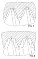
- FIGS. 7 and 8 show that it is also possible to thread both the bolt and the Train mother accordingly.
- the invention further relates to a tool for producing the thread and finally it is proposed that the self-locking thread according to the invention can be used with great advantage as a surgical aid.
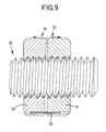
- FIG. 9 shows a double nut arrangement with the two nuts 30 and 31, which are arranged on a threaded rod 32.
- the two nuts 30 and 31 are connected by a connecting means, e.g. B. a pin 33, rotatably connected to each other, this pin 33 can be easily removed, so that then the two nuts 30, 31 can be rotated against each other, in the direction of arrows 34 and 35th
- the double nut principle according to the invention would not be achieved by simply connecting two nuts in series, rather the preceding nut part 30 must have the clamping surface facing backwards and the trailing nut part 31 must have the clamping surface facing forward.
- Directional neutrality remains, however, because this principle is retained by turning the nuts.
- a disc which is concave on its contact side.
- a washer which is concave on at least one side, can be inserted, which then generates a certain spring force when the nut is tightened.
- Such a washer can of course also be placed in the area of a conventional nut or in the area of a bolt head having a flat contact surface.
Abstract
Description
Die Erfindung bezieht sich auf ein selbsthemmendes Gewinde zur Verschraubung bei zwei miteinander durch Schraubung zu verbindenden Elementen gemäß dem Oberbegriff des Hauptanspruches.The invention relates to a self-locking thread for screwing in two elements to be connected by screwing according to the preamble of the main claim.
Ein gattungsbildendes selbsthemmendes Gewinde wird in der DE-26 45 519 C2 beschrieben. Dieses bekannte Gewinde kennzeichnet sich dadurch, daß der Gewindefuß zu einer schräg zur Gewindeachse verlaufenden Rampe ausgebildet ist und der Neigungswinkel der Rampe zur Gewindeachse jeweils konstant bleibend 15° bis 45°, vorzugsweise 20° bis 35° beträgt.A generic self-locking thread is described in DE-26 45 519 C2. This known thread is characterized in that the thread base is designed to form an inclined ramp to the thread axis and the angle of inclination of the ramp to the thread axis is in each case constant 15 ° to 45 °, preferably 20 ° to 35 °.
Diese bekannte Anordnung hat den Nachteil, daß eine selbsthemmende Wirkung nur in einer Schraubrichtung erreichbar ist. In vielen Einsatzzwecken in der Technik ist es aber erwünscht, eine Mutter auf einer Gewindestange nach beiden Seiten zu arretieren.This known arrangement has the disadvantage that a self-locking effect can only be achieved in one screwing direction. In many technical applications, however, it is desirable to lock a nut on both sides of a threaded rod.
Die erforderliche Längsverschiebung, um zur Selbsthemmung zu kommen, ist relativ groß.The longitudinal displacement required to achieve self-locking is relatively large.
Der Erfindung liegt die Aufgabe zugrunde, das gattungsbildende Gewinde derart zu verbessern, daß es vor allen Dingen in beiden Richtungen wirksam wird, wobei weiterhin die Kontaktfläche zwischen den beiden zusammenwirkenden Elementen erhöht werden soll, aber nur als Linienkontakt vorliegen soll.The invention has for its object to improve the generic thread in such a way that it is effective above all in both directions, while the contact area between the two interacting elements should be increased, but should only be a line contact.
Diese der Erfindung zugrundeliegende Aufgabe wird durch die Lehre des Hauptanspruches gelöst.This object on which the invention is based is achieved by the teaching of the main claim.
Vorteilhafte Ausgestaltungen sind in den Unteransprüchen erläutert.Advantageous configurations are explained in the subclaims.
Mit anderen Worten ausgedruckt wird vorgeschlagen, daß ein Element ein Gewindeprofil aufweist, das hinsichtlich der Kontaktflächen im wesentlichen zum anderen Partner oder zu einem Normalgewinde inkonkruent ist. Weiterhin wird erreicht, daß die Gewindeflächen von Schraube und Mutter im wesentlichen miteinander nur einen spiralförmigen Linienkontakt aufweisen und daß dieser Linienkontakt an der Gewindebasis, an der Gewindekrone oder an beiden Stellen der beiden Elemente erfolgt. Weiterhin ist vorgesehen, daß der erste Gewindegang des veränderten Elementes eine konvexe Gewindefläche aufweist, die nur an der Gewindebasis mit der Schraubenkrone bzw. umgekehrt einen reduzierten Flächenkontakt aufweist. Hierdurch läßt sich der erste Teil der Mutter normal anziehen, d. h. ohne große Reibungen und vorzugsweise ist ein kontinuierlicher Übergang vom ersten, noch Flächenkontakt aufweisenden Gewindegang zum Spezialgewinde mit Linienkontakt vorgesehen.In other words, it is proposed that an element has a thread profile that is essentially inconsistent with the other partner or with a normal thread with regard to the contact surfaces. Furthermore, it is achieved that the thread surfaces of the screw and nut essentially have only a spiral line contact with one another and that this line contact takes place on the thread base, on the thread crown or at both points of the two elements. It is further provided that the first thread of the modified element has a convex thread surface, which has reduced surface contact only on the thread base with the screw crown or vice versa. This allows the first part of the mother to be tightened normally. H. without major friction and preferably a continuous transition from the first thread still having surface contact to the special thread with line contact is provided.
Gegenüber dem gattungsbildenden, selbsthemmenden Gewinde ist die Längsverschiebung geringer, insbesondere wenn die Klemmflächen wie vorgeschlagen gewölbt ausgebildet sind, da durch die Kurve die Gewindekrone schnell mit der Mutterbasis Kontakt aufnimmt.Compared to the generic, self-locking thread, the longitudinal displacement is less, in particular if the clamping surfaces are curved as proposed, since the thread crown quickly makes contact with the nut base through the curve.
Auch wird bei der erfindungsgemäßen Einrichtung ein besserer Lauf erreicht, da die Schraube im Gewinde zentriert gehalten wird.Better running is also achieved in the device according to the invention, since the screw is kept centered in the thread.
Gemäß einem weiteren Merkmal der Erfindung ist vorgesehen, daß die Klemmflächen gewölbt, und zwar vorzugsweise konkav-konvex ausgebildet sind. Durch diese konkav-konvexe Wölbung wird eine gute Zentrierung des Gewindegrates und damit ein besserer Freilauf gewährleistet, wenn noch kein stärkerer axialer Verschiebedruck auftritt. Die Mitdrehwirkung auf die Schraube wird dadurch erheblich verringert. Außerdem werden längere Klemmwege erzielt, ohne daß eine entsprechend weite seitliche Verschiebung erforderlich wäre. Außerdem erfolgt eine schnellere Verstärkung der Klemmwirkung durch die konvexe Form der Gewindeflanke und es kommt dadurch zu einer geringeren seitlichen Verschiebung. Weiterhin wird eine stabilere Arretierung des Gewindegrates im Bereich des konvex-konkaven Übergangs erreicht, da hier eine größere Annäherung an eine Parallelität zur Schraubenachse erreicht wird. Die konvexe Form am Anfang der konvex-konkaven Klemmflanke führt zu einer massenmäßigen Stabilisierung und wirkt Gewindeabscherungen entgegen.According to a further feature of the invention it is provided that the clamping surfaces are curved, preferably concave-convex. This concave-convex curvature ensures good centering of the thread burr and thus better freewheeling if no stronger axial displacement pressure occurs yet. This significantly reduces the co-rotation effect on the screw. In addition, longer clamping distances are achieved without a correspondingly wide lateral displacement being necessary. In addition, the convex shape of the thread flank reinforces the clamping effect more quickly, resulting in less lateral displacement. Furthermore, a more stable locking of the thread burr is achieved in the region of the convex-concave transition, since here a greater approximation to a parallelism to the screw axis is achieved. The convex shape at the beginning of the convex-concave clamping flank leads to mass stabilization and counteracts thread shear.
Durch die beidseitige Wölbung wird das Prinzip des Kontermutterns möglich. Die Muttern können nicht verkehrt herum aufgesetzt werden und es entfällt eine Unterscheidung in links- oder rechtsdrehende Muttern; dadurch eine Halbierung der Lagerungserfordernisse.The principle of lock nuts is made possible by the curvature on both sides. The nuts cannot be placed the wrong way round and there is no distinction between left and right turning Nuts; thereby halving the storage requirements.
Gemäß einem wesentlichen Merkmal der Erfindung wird ein sogenanntes "Doppelmutterprinzip" vorgeschlagen. Hierzu werden zwei Muttern einerseits über eine lösbare Verbindung drehfest miteinander verbunden, können nach Lösen dieser Verbindung aber gegeneinander verdreht werden, wobei der vorangehende Mutterteil die Klemmfläche nach rückwärts und der nachgehende Mutterteil die Klemmfläche nach vorwärts ausgerichtet hat. Die Richtungsneutralität bleibt aber erhalten, da durch Umdrehen der Muttern dieses Prinzip erhalten bleibt. Die Doppelmutter weist daher zwei voneinander unterschiedliche Gewindehälften auf und muß speziell hergestellt werden. Dazu muß z. B. auch die Verbindung der beiden Mutterhälften unter Freilauf des Gewindes gesichert sein. Die Wirkung dieses Doppelmutterprinzips ist, daß bei nur einseitig vorhandener Klemmfläche, z. B. zwei Muttern mit selbsthemmendem Gewinde, nun eine Richtungsneutralität gegeben ist. Dadurch, daß die beiden Muttern eine Einheit bilden, wird das Aufbringen der Muttern erleichtert und beschleunigt. Auf Gewindestangen können nun Muttern z. B. mit Gewindebohrungen versehene Elemente fest verankert werden, ohne daß eine Anlagerungsfläche erforderlich ist. Der Verriegelungsprozeß erfolgt unter vorbestehender Vorspannung durch Verdrehen der Mutternteile gegeneinander. Da nur eine Verschiebung um Bruchteile eines Millimeters in axialer Richtung erfolgt ohne eine Rotationsbewegung des Partners, wirkt sich die Vorspannkraft hauptsächlich im Sinne einer verstärkten Klemmwirkung aus.According to an essential feature of the invention, a so-called "double nut principle" is proposed. For this purpose, two nuts are connected to one another in a rotationally fixed manner via a releasable connection, but can be rotated against each other after this connection has been released, the preceding nut part having the clamping surface facing backwards and the subsequent nut part having the clamping surface facing forward. The directional neutrality is maintained, however, because this principle is retained by turning the nuts. The double nut therefore has two different thread halves and must be specially manufactured. For this, z. B. the connection of the two nut halves can be secured with free running of the thread. The effect of this double nut principle is that with only one-sided clamping surface, z. B. two nuts with self-locking thread, a directional neutrality is now given. The fact that the two nuts form a unit makes the application of the nuts easier and faster. On threaded rods nuts can now z. B. elements with threaded holes are firmly anchored without the need for an attachment surface. The locking process takes place under pre-existing prestressing by turning the nut parts against each other. Since there is only a fraction of a millimeter shift in the axial direction without a rotational movement of the partner, the pretensioning force mainly acts in the sense of an increased clamping effect.
Ausführungsbeispiele der Erfindung werden nachfolgend anhand der Zeichnungen erläutert. Die Zeichnungen zeigen dabei in
- Fig. 1
- in einer sehr schematischen Darstellung eine Mutter mit erfindungsgemäßen Gewinde, in
- Fig. 2
- ebenfalls in einer schematischen Darstellung einen Bolzen mit erfindungsgemäßen Gewinde, in
- Fig. 3
- das Zusammenspiel zwischen Bolzen und Mutter, wobei die Mutter mit dem erfindungsgemäßen Gewinde ausgerüstet ist und die beiden Bauteile ohne Belastung und mit Belastung dargestellt sind, in
- Fig. 4
- eine der Fig. 3 entsprechende Darstellung, um das Zusammenspiel zwischen Bolzen und Mutter zu verdeutlichen, wobei der Bolzen mit dem erfindungsgemäßen Gewinde ausgerüstet ist, in
- Fig. 5
- die Ausbildung der ersten Gewindegänge als Übergang vom Normalgewinde zum Spezialgewinde, in
- Fig. 6
- eine besondere Ausbildung der Grate der Gewindegänge, in den
- Fig. 7 und 8
- eine abgewandelte Ausführungsform und in
- Fig. 9
- zwei hintereinander geschaltete Muttern.
- Fig. 1
- in a very schematic representation, a nut with a thread according to the invention, in
- Fig. 2
- also in a schematic representation a bolt with a thread according to the invention, in
- Fig. 3
- the interaction between bolt and nut, the nut being equipped with the thread according to the invention and the two components being shown without load and with load, in
- Fig. 4
- a representation corresponding to FIG. 3 in order to clarify the interaction between the bolt and the nut, the bolt being equipped with the thread according to the invention, in
- Fig. 5
- the formation of the first threads as a transition from normal thread to special thread, in
- Fig. 6
- a special training of the burrs of the threads in the
- 7 and 8
- a modified embodiment and in
- Fig. 9
- two nuts connected in series.
In den Zeichnungen ist mit 1 ein ein normales Gewinde aufweisender Bolzen, mit 2 eine ein normales Gewinde aufweisende Mutter, mit 10 ein das erfindungsgemäße Gewinde aufweisender Bolzen und mit 20 eine das erfindungsgemäße Gewinde aufweisende Mutter bezeichnet.In the drawings, 1 denotes a bolt with a normal thread, 2 with a nut with a normal thread, 10 with a bolt with the thread according to the invention, and with 20 denotes a nut having the thread according to the invention.
Aus der Darstellung in Fig. 1 ist erkennbar, daß die Flanken 3, 4 der Mutter 20 steiler gestellt sind als die Flanken 5 und 6 eines normalen Gewindes eines normalen Bolzens 1, so daß, wenn - wie dies deutlich die Fig. 3 zeigt - der Bolzen 1 in die Mutter 20 eingesetzt ist, die zusammenwirkenden Flächen der Gewinde inkongruent sind. Im Gewindefuß 15 sind zwei Klemmflächen 8, 9 vorgesehen, die gewölbt ausgebildet sind, wobei die Wölbung von dem anderen Element aus gesehen konvex gestaltet ist.It can be seen from the illustration in FIG. 1 that the
Wie dies dann deutlich wiederum die Fig. 3 zeigt, kommt bei einer Bewegung des Bolzens 1 gegenüber der Mutter 20 oder umgekehrt der Grat des normalen Gewindes des Bolzens sehr schnell zur Anlage an der gewölbten Fläche der Klemmfläche 8, 9, so daß hier ein Linienkontakt entsteht.3, when the bolt 1 moves relative to the
Um diesen Linienkontakt noch zu verbessern, sind die Grate 7 der Mutter 20 abgeflacht, d. h. stumpf abgeschnitten, so daß auch hier - wie dies deutlich die Fig. 3 zeigt - bei Druckaufnahme zwischen Mutter 20 und Bolzen 1 ein Linienkontakt hergestellt wird.To further improve this line contact, the
In gleicher Weise ist der Bolzen 10 ausgebildet, d. h. die Flanken des Gewindes sind steiler gestellt als die Flanken der Mutter 2, die mit Normalgewinde ausgerüstet ist. Die Figuren zeigen außerdem, daß bei dem erfindungsgemäß ausgebildeten Bauteil, d. h. entweder dem Bolzen 10 oder der Mutter 20, der erste Gewindegang eine konvexe Gewindefläche 11 aufweist, die bei Druckaufnahme nur an der Gewindebasis mit dem anderen Element zusammenwirkt. Vorzugsweise kann dabei - wie dies auch deutlich die Fig. 2 zeigt - ein kontinuierlicher Übergang vom ersten, noch Flächenkontakt aufweisenden Gewindegang zum Spezialgewinde hergestellt werden.In the same way, the
Während in den Fig. 1 bis 5 jeweils Gewinde dargestellt sind, bei denen entweder die Mutter oder der Bolzen gemäß der Erfindung bearbeitet worden ist, zeigen die Fig. 7 und 8, daß es auch möglich ist, die Gewinde sowohl des Bolzens wie auch der Mutter entsprechend auszubilden.1 to 5 each show threads in which either the nut or the bolt has been machined according to the invention, FIGS. 7 and 8 show that it is also possible to thread both the bolt and the Train mother accordingly.
Die Erfindung bezieht sich weiterhin auf ein Werkzeug zur Herstellung des Gewindes und schließlich wird vorgeschlagen, daß das erfindungsgemäße selbsthemmende Gewinde mit großem Vorteil als chirurgisches Hilfsmittel eingesetzt werden kann.The invention further relates to a tool for producing the thread and finally it is proposed that the self-locking thread according to the invention can be used with great advantage as a surgical aid.
In Fig. 9 ist eine Doppelmutteranordnung mit den beiden Muttern 30 und 31 dargestellt, die auf einer Gewindestange 32 angeordnet sind. Die beiden Muttern 30 und 31 sind über ein Verbindungsmittel , z. B. einen Stift 33, drehfest miteinander verbunden, wobei dieser Stift 33 leicht entnommen werden kann, so daß dadurch dann die beiden Muttern 30, 31 gegeneinander gedreht werden können, und zwar im Sinne der Pfeile 34 und 35.9 shows a double nut arrangement with the two
Das erfindungsgemäße Doppelmutterprinzip würde nicht durch das bloße Hintereinanderschalten von zwei Muttern erreicht, vielmehr muß der vorangehende Mutternteil 30 die Klemmfläche nach rückwärts und der nachgehende Mutternteil 31 die Klemmfläche nach vorwärts ausgerichtet haben. Die Richtungsneutralität bleibt aber erhalten, da durch Umdrehen der Muttern dieses Prinzip erhalten bleibt.The double nut principle according to the invention would not be achieved by simply connecting two nuts in series, rather the preceding
Gemäß der Erfindung kann weiterhin so vorgegangen werden, daß durch eine an ihrer Anlageseite konkav ausgebildete Scheibe eine maximale Pressung erzielbar ist. So kann beispielsweise zwischen die beiden Muttern 30 und 31 eine solche, wenigstens einseitig konkav ausgebildete Scheibe eingesetzt werden, die dann beim Zusammenziehen der Mutter eine gewisse Federkraft erzeugt. Eine solche Scheibe kann natürlich auch im Bereich einer üblichen Mutter angesetzt werden oder auch im Bereich eines eine ebene Anlagefläche aufweisenden Bolzenkopfes.According to the invention, it is also possible to proceed in such a way that maximum pressure can be achieved by a disc which is concave on its contact side. For example, between the two
Claims (15)
Priority Applications (1)
| Application Number | Priority Date | Filing Date | Title |
|---|---|---|---|
| AT91101116T ATE100539T1 (en) | 1990-02-09 | 1991-01-29 | SELF-LOCKING THREAD. |
Applications Claiming Priority (2)
| Application Number | Priority Date | Filing Date | Title |
|---|---|---|---|
| DE4003892 | 1990-02-09 | ||
| DE4003892A DE4003892A1 (en) | 1990-02-09 | 1990-02-09 | SELF-LOCKING THREAD |
Publications (2)
| Publication Number | Publication Date |
|---|---|
| EP0441224A1 true EP0441224A1 (en) | 1991-08-14 |
| EP0441224B1 EP0441224B1 (en) | 1994-01-19 |
Family
ID=6399754
Family Applications (1)
| Application Number | Title | Priority Date | Filing Date |
|---|---|---|---|
| EP91101116A Expired - Lifetime EP0441224B1 (en) | 1990-02-09 | 1991-01-29 | Selfblocking thread |
Country Status (5)
| Country | Link |
|---|---|
| EP (1) | EP0441224B1 (en) |
| JP (1) | JP2664546B2 (en) |
| AT (1) | ATE100539T1 (en) |
| DE (2) | DE4003892A1 (en) |
| ES (1) | ES2049053T3 (en) |
Cited By (7)
| Publication number | Priority date | Publication date | Assignee | Title |
|---|---|---|---|---|
| EP0478928A2 (en) * | 1990-10-05 | 1992-04-08 | Hartmut Flaig | Screw impeding nut |
| DE4132923A1 (en) * | 1991-10-04 | 1992-04-16 | Knecht Filterwerke Gmbh | Safe screw connection - has protrusion of thread to engage into counter thread |
| EP0524489A1 (en) * | 1991-07-25 | 1993-01-27 | Anton Prof. Dr. Härle | Self-locking screw-thread |
| US9388845B2 (en) | 2010-11-30 | 2016-07-12 | Nitto Seiko Co., Ltd. | Locking screw |
| US9523554B2 (en) | 2014-04-03 | 2016-12-20 | Magpul Industries Corp. | Firearm accessory mounting interface |
| CN106513876A (en) * | 2015-09-11 | 2017-03-22 | 安东检测有限公司 | Coping plate, coping device and coping equipment |
| US9921029B2 (en) | 2014-01-10 | 2018-03-20 | Magpul Industries Corp. | Connector |
Families Citing this family (1)
| Publication number | Priority date | Publication date | Assignee | Title |
|---|---|---|---|---|
| DE4206885A1 (en) * | 1992-03-05 | 1993-09-23 | Schuermann & Hilleke Gmbh | Bolt with self-locking thread effected by thread change - has enlarged flank angle between core dia. and thread dia. which is smaller than flank dia. |
Citations (6)
| Publication number | Priority date | Publication date | Assignee | Title |
|---|---|---|---|---|
| DE616084C (en) * | 1932-09-17 | 1935-07-23 | Bedrich Rosenbaum | Screw nut that can be used on both sides for dynamic loads |
| US2787796A (en) * | 1952-09-30 | 1957-04-09 | Rosan Joseph | Method of converting standard threads into locking threads |
| FR2408061A1 (en) * | 1977-11-04 | 1979-06-01 | Tomoyasu Yoshioki | SELF-LOCKING THREADED PART |
| DE3219264C1 (en) * | 1982-05-21 | 1983-04-21 | Siemens AG, 1000 Berlin und 8000 München | Terminal screw thread for a connecting terminal |
| GB2131905A (en) * | 1982-12-14 | 1984-06-27 | Mark Hattan | Forming threaded elements having self-locking action |
| US4870957A (en) * | 1988-12-27 | 1989-10-03 | Marlowe Goble E | Ligament anchor system |
Family Cites Families (2)
| Publication number | Priority date | Publication date | Assignee | Title |
|---|---|---|---|---|
| US4150702A (en) * | 1978-02-10 | 1979-04-24 | Holmes Horace D | Locking fastener |
| JPH024247Y2 (en) * | 1985-04-30 | 1990-01-31 |
-
1990
- 1990-02-09 DE DE4003892A patent/DE4003892A1/en not_active Withdrawn
-
1991
- 1991-01-29 EP EP91101116A patent/EP0441224B1/en not_active Expired - Lifetime
- 1991-01-29 DE DE91101116T patent/DE59100871D1/en not_active Expired - Fee Related
- 1991-01-29 AT AT91101116T patent/ATE100539T1/en not_active IP Right Cessation
- 1991-01-29 ES ES91101116T patent/ES2049053T3/en not_active Expired - Lifetime
- 1991-02-07 JP JP3016510A patent/JP2664546B2/en not_active Expired - Lifetime
Patent Citations (6)
| Publication number | Priority date | Publication date | Assignee | Title |
|---|---|---|---|---|
| DE616084C (en) * | 1932-09-17 | 1935-07-23 | Bedrich Rosenbaum | Screw nut that can be used on both sides for dynamic loads |
| US2787796A (en) * | 1952-09-30 | 1957-04-09 | Rosan Joseph | Method of converting standard threads into locking threads |
| FR2408061A1 (en) * | 1977-11-04 | 1979-06-01 | Tomoyasu Yoshioki | SELF-LOCKING THREADED PART |
| DE3219264C1 (en) * | 1982-05-21 | 1983-04-21 | Siemens AG, 1000 Berlin und 8000 München | Terminal screw thread for a connecting terminal |
| GB2131905A (en) * | 1982-12-14 | 1984-06-27 | Mark Hattan | Forming threaded elements having self-locking action |
| US4870957A (en) * | 1988-12-27 | 1989-10-03 | Marlowe Goble E | Ligament anchor system |
Cited By (15)
| Publication number | Priority date | Publication date | Assignee | Title |
|---|---|---|---|---|
| EP0478928A2 (en) * | 1990-10-05 | 1992-04-08 | Hartmut Flaig | Screw impeding nut |
| DE4031602A1 (en) * | 1990-10-05 | 1992-04-09 | Hartmut Flaig | HAMMER NUT |
| EP0478928A3 (en) * | 1990-10-05 | 1992-09-02 | Hartmut Flaig | Screw impeding nut |
| EP0524489A1 (en) * | 1991-07-25 | 1993-01-27 | Anton Prof. Dr. Härle | Self-locking screw-thread |
| EP0568106A1 (en) * | 1991-07-25 | 1993-11-03 | Anton Prof. Dr. Härle | Self-locking screw-thread |
| DE4132923A1 (en) * | 1991-10-04 | 1992-04-16 | Knecht Filterwerke Gmbh | Safe screw connection - has protrusion of thread to engage into counter thread |
| US9388845B2 (en) | 2010-11-30 | 2016-07-12 | Nitto Seiko Co., Ltd. | Locking screw |
| US9921029B2 (en) | 2014-01-10 | 2018-03-20 | Magpul Industries Corp. | Connector |
| US10371482B2 (en) | 2014-01-10 | 2019-08-06 | Magpul Industries Corp. | Connector |
| US9523554B2 (en) | 2014-04-03 | 2016-12-20 | Magpul Industries Corp. | Firearm accessory mounting interface |
| US9976832B2 (en) | 2014-04-03 | 2018-05-22 | Magpul Industries Corp. | Firearm accessory mounting interface |
| US10520279B2 (en) | 2014-04-03 | 2019-12-31 | Magpul Industries Corp. | Firearm accessory mounting interface |
| US11002509B2 (en) | 2014-04-03 | 2021-05-11 | Magpul Industries Corp. | Firearm accessory mounting interface |
| US11536535B2 (en) | 2014-04-03 | 2022-12-27 | Magpul Industries Corp. | Firearm accessory mounting interface |
| CN106513876A (en) * | 2015-09-11 | 2017-03-22 | 安东检测有限公司 | Coping plate, coping device and coping equipment |
Also Published As
| Publication number | Publication date |
|---|---|
| ES2049053T3 (en) | 1994-04-01 |
| DE59100871D1 (en) | 1994-03-03 |
| JP2664546B2 (en) | 1997-10-15 |
| JPH05196025A (en) | 1993-08-06 |
| ATE100539T1 (en) | 1994-02-15 |
| DE4003892A1 (en) | 1991-08-14 |
| EP0441224B1 (en) | 1994-01-19 |
Similar Documents
| Publication | Publication Date | Title |
|---|---|---|
| DE60119882T2 (en) | FIXING DEVICE | |
| EP0604508B1 (en) | Endoprosthesis with a visco-elastic plastic prosthesis component | |
| DE4401746C2 (en) | T mother | |
| DE4307090B4 (en) | Nut, especially wheel nut | |
| EP2131048B1 (en) | Locking element for a screw connection and such a screw connection | |
| DE2457143B2 (en) | Locking screw | |
| DE2720548A1 (en) | SAFETY NUT | |
| DE3703031A1 (en) | FASTENING DEVICE WITH A U-NUT | |
| DE4340504A1 (en) | Device for preventing the loosening of a screw arrangement | |
| DE102005006592A1 (en) | Process for the primary molding of a molded part and molded part produced by primary molding, in particular nut | |
| DE3032167C2 (en) | Nut-bolt connection secured against unintentional loosening | |
| EP0441224B1 (en) | Selfblocking thread | |
| DE3032166C2 (en) | Bolt-nut connection secured against unintentional loosening | |
| EP0534001B1 (en) | Screwed connections for connecting two structural members at some distance, in particular sheets | |
| DE3027947C2 (en) | Arrangement for fastening a first part to a second part by means of a bolt | |
| EP2044341B1 (en) | Safety nut | |
| DE102004020000A1 (en) | Suspension element | |
| EP0568106B1 (en) | Self-locking screw-thread | |
| EP0460264A1 (en) | Screw | |
| DE19906480A1 (en) | Rotary blade holder e.g. for haymaking machine or mower | |
| DE2811108A1 (en) | Toothed locking washer for nut or bolt - has tooth rear faces steeper on side furthest from screw head | |
| DE2443013A1 (en) | FASTENING ELEMENT | |
| EP0423474B1 (en) | Device for the releasable fastening of two profiled rods | |
| WO2017102376A1 (en) | Threaded element | |
| EP3354907B1 (en) | Notched disc set |
Legal Events
| Date | Code | Title | Description |
|---|---|---|---|
| PUAI | Public reference made under article 153(3) epc to a published international application that has entered the european phase |
Free format text: ORIGINAL CODE: 0009012 |
|
| AK | Designated contracting states |
Kind code of ref document: A1 Designated state(s): AT CH DE ES FR GB IT LI NL SE |
|
| 17P | Request for examination filed |
Effective date: 19911217 |
|
| 17Q | First examination report despatched |
Effective date: 19920518 |
|
| GRAA | (expected) grant |
Free format text: ORIGINAL CODE: 0009210 |
|
| AK | Designated contracting states |
Kind code of ref document: B1 Designated state(s): AT CH DE ES FR GB IT LI NL SE |
|
| REF | Corresponds to: |
Ref document number: 100539 Country of ref document: AT Date of ref document: 19940215 Kind code of ref document: T |
|
| REF | Corresponds to: |
Ref document number: 59100871 Country of ref document: DE Date of ref document: 19940303 |
|
| ET | Fr: translation filed | ||
| ITF | It: translation for a ep patent filed |
Owner name: CALVANI SALVI E VERONELLI S.R.L. |
|
| REG | Reference to a national code |
Ref country code: ES Ref legal event code: FG2A Ref document number: 2049053 Country of ref document: ES Kind code of ref document: T3 |
|
| GBT | Gb: translation of ep patent filed (gb section 77(6)(a)/1977) |
Effective date: 19940321 |
|
| PLBE | No opposition filed within time limit |
Free format text: ORIGINAL CODE: 0009261 |
|
| STAA | Information on the status of an ep patent application or granted ep patent |
Free format text: STATUS: NO OPPOSITION FILED WITHIN TIME LIMIT |
|
| 26N | No opposition filed | ||
| EAL | Se: european patent in force in sweden |
Ref document number: 91101116.1 |
|
| REG | Reference to a national code |
Ref country code: CH Ref legal event code: PL |
|
| REG | Reference to a national code |
Ref country code: CH Ref legal event code: AEN Free format text: DAS PATENT IST AUFGRUND DES WEITERBEHANDLUNGSANTRAGS VOM29.08.1996 REAKTIVIERT WORDEN. |
|
| PGFP | Annual fee paid to national office [announced via postgrant information from national office to epo] |
Ref country code: CH Payment date: 19980501 Year of fee payment: 8 |
|
| PGFP | Annual fee paid to national office [announced via postgrant information from national office to epo] |
Ref country code: GB Payment date: 19990125 Year of fee payment: 9 |
|
| PG25 | Lapsed in a contracting state [announced via postgrant information from national office to epo] |
Ref country code: LI Free format text: LAPSE BECAUSE OF NON-PAYMENT OF DUE FEES Effective date: 19990131 Ref country code: CH Free format text: LAPSE BECAUSE OF NON-PAYMENT OF DUE FEES Effective date: 19990131 |
|
| REG | Reference to a national code |
Ref country code: CH Ref legal event code: PL |
|
| PGFP | Annual fee paid to national office [announced via postgrant information from national office to epo] |
Ref country code: FR Payment date: 19991117 Year of fee payment: 10 |
|
| PGFP | Annual fee paid to national office [announced via postgrant information from national office to epo] |
Ref country code: AT Payment date: 20000126 Year of fee payment: 10 |
|
| PGFP | Annual fee paid to national office [announced via postgrant information from national office to epo] |
Ref country code: SE Payment date: 20000127 Year of fee payment: 10 Ref country code: NL Payment date: 20000127 Year of fee payment: 10 |
|
| PG25 | Lapsed in a contracting state [announced via postgrant information from national office to epo] |
Ref country code: GB Free format text: LAPSE BECAUSE OF NON-PAYMENT OF DUE FEES Effective date: 20000129 |
|
| PGFP | Annual fee paid to national office [announced via postgrant information from national office to epo] |
Ref country code: ES Payment date: 20000131 Year of fee payment: 10 |
|
| GBPC | Gb: european patent ceased through non-payment of renewal fee |
Effective date: 20000129 |
|
| PG25 | Lapsed in a contracting state [announced via postgrant information from national office to epo] |
Ref country code: AT Free format text: LAPSE BECAUSE OF NON-PAYMENT OF DUE FEES Effective date: 20010129 |
|
| PG25 | Lapsed in a contracting state [announced via postgrant information from national office to epo] |
Ref country code: SE Free format text: LAPSE BECAUSE OF NON-PAYMENT OF DUE FEES Effective date: 20010130 Ref country code: ES Free format text: LAPSE BECAUSE OF NON-PAYMENT OF DUE FEES Effective date: 20010130 |
|
| PG25 | Lapsed in a contracting state [announced via postgrant information from national office to epo] |
Ref country code: NL Free format text: LAPSE BECAUSE OF NON-PAYMENT OF DUE FEES Effective date: 20010801 |
|
| EUG | Se: european patent has lapsed |
Ref document number: 91101116.1 |
|
| PG25 | Lapsed in a contracting state [announced via postgrant information from national office to epo] |
Ref country code: FR Free format text: LAPSE BECAUSE OF NON-PAYMENT OF DUE FEES Effective date: 20010928 |
|
| NLV4 | Nl: lapsed or anulled due to non-payment of the annual fee |
Effective date: 20010801 |
|
| REG | Reference to a national code |
Ref country code: FR Ref legal event code: ST |
|
| REG | Reference to a national code |
Ref country code: ES Ref legal event code: FD2A Effective date: 20020916 |
|
| PGFP | Annual fee paid to national office [announced via postgrant information from national office to epo] |
Ref country code: DE Payment date: 20040719 Year of fee payment: 14 |
|
| PG25 | Lapsed in a contracting state [announced via postgrant information from national office to epo] |
Ref country code: IT Free format text: LAPSE BECAUSE OF NON-PAYMENT OF DUE FEES;WARNING: LAPSES OF ITALIAN PATENTS WITH EFFECTIVE DATE BEFORE 2007 MAY HAVE OCCURRED AT ANY TIME BEFORE 2007. THE CORRECT EFFECTIVE DATE MAY BE DIFFERENT FROM THE ONE RECORDED. Effective date: 20050129 |
|
| PG25 | Lapsed in a contracting state [announced via postgrant information from national office to epo] |
Ref country code: DE Free format text: LAPSE BECAUSE OF NON-PAYMENT OF DUE FEES Effective date: 20050802 |