EP0441484A2 - Method of guiding a web through a dryer and apparatus for carrying out the method - Google Patents
Method of guiding a web through a dryer and apparatus for carrying out the method Download PDFInfo
- Publication number
- EP0441484A2 EP0441484A2 EP91300308A EP91300308A EP0441484A2 EP 0441484 A2 EP0441484 A2 EP 0441484A2 EP 91300308 A EP91300308 A EP 91300308A EP 91300308 A EP91300308 A EP 91300308A EP 0441484 A2 EP0441484 A2 EP 0441484A2
- Authority
- EP
- European Patent Office
- Prior art keywords
- web
- air
- bars
- dryer
- air bars
- Prior art date
- Legal status (The legal status is an assumption and is not a legal conclusion. Google has not performed a legal analysis and makes no representation as to the accuracy of the status listed.)
- Granted
Links
Images


Classifications
-
- F—MECHANICAL ENGINEERING; LIGHTING; HEATING; WEAPONS; BLASTING
- F26—DRYING
- F26B—DRYING SOLID MATERIALS OR OBJECTS BY REMOVING LIQUID THEREFROM
- F26B13/00—Machines and apparatus for drying fabrics, fibres, yarns, or other materials in long lengths, with progressive movement
- F26B13/10—Arrangements for feeding, heating or supporting materials; Controlling movement, tension or position of materials
- F26B13/101—Supporting materials without tension, e.g. on or between foraminous belts
- F26B13/104—Supporting materials without tension, e.g. on or between foraminous belts supported by fluid jets only; Fluid blowing arrangements for flotation dryers, e.g. coanda nozzles
Definitions
- This invention relates to web supporting apparatus and is more particularly concerned with a web supporting and guiding device for a web drying apparatus whereby a lengthwise moving web is floatingly supported and maintained in a straight path (i.e. centered with respect to the longitudinal centerline of the web) throughout the length of the web drying apparatus.
- One common arrangement for contactlessly supporting a web comprises upper and lower sets of air bars extending along a substantially horizontal stretch of the web. Air issuing from the lower set of air bars floatingly supports the web, and air issuing from the upper set of air bars steadies the web to maintain it substantially straight and at a substantially constant distance from the air bars of both sets.
- the air blown from both sets of air bars is usually heated to expedite web drying, and typically the air bar array is inside an enclosure which is maintained at a slightly subatmospheric pressure by an exhaust blower that draws off the volatiles emanating from the web.
- Web dryers are used in many printing and graphics applications, such as the processing of photographic film, web offset printing, and other types of printing.
- web dryers having very long length, often as long as 150 feet, are commonly used.
- the greater the ratio of the length of the dryer to the width of the web hereinafter referred to as the "length to width ratio"
- some webs, such as thin plastic films naturally take on a "banana-shaped" curve when they are laid flat, as in a dryer, thereby exacerbating the problems of web weave and shift.
- Web shifting and weaving may also result when the web tension is low, and when a lighter weight web, such as polyester film, is used.
- the travelling web When the travelling web exits the drying apparatus it is generally wrapped around one or more rotating take-up members, such as chill rolls.
- rotating take-up members such as chill rolls.
- web weave or shift takes place as the web travels through the dryer, the web will correspondingly shift or weave as it contacts the rotating take-up member. Unless the web can be brought back to a straight orientation with respect to the centerline, the web will not wrap properly and the press must be shut down. This results in costly downtime and waste.
- a web may be floatingly supported and urged in a substantially straight path at points in the dryer where it has a tendency to weave or shift as it travels through a web drying apparatus.
- the present invention relates to an apparatus for handling and guiding a running web. More particularly, the present invention relates to an apparatus which both floatingly supports a web, and maintains the web in a substantially straight path as it travels through a dryer. The present invention further relates to a dryer comprising such web handling and guiding apparatus.
- the web handling and guiding apparatus of the present invention comprises a steerable air bar assembly comprising: i) one or more adjustable air bars, each having an elongated surface from which air may be discharged, said surface being in opposing relation to the running web, and each having two ends: ii) air supply means, in fluid communication with the air bars; and iii) adjustment means for altering the orientation of the elongated surfaces of the adjustable air bars such that the orientation of one or both of the surfaces is adjustable with respect to the running web.
- each said surface rotates about an axis which is substantially parallel to the longitudinal centerline of the running web.
- each said surface may rotate about an axis which is substantially perpendicular to the longitudinal centerline of the running web.
- Said steerable air bar assembly is positioned in a web dryer such that the web is guided through the dryer in a substantially straight path.
- One or more such steerable air bar assemblies can be used in a web dryer.
- the dryer can also include one or more fixed air bars.
- the apparatus further comprises in combination with the steerable air bar assembly, back pressure means for creating an opposing force to urge the web back to a substantially centered position.
- Said back pressure means preferably comprises one or more edge dams preferably disposed at or near the ends of one or more fixed air bars in the web dryer.
- the air supply means of the steerable air bar apparatus comprises a header which is sealingly joined at one end to a flexible air duct.
- the air bar is disposed adjacent the header such that air flows from the air duct into the header, and from the header into the air bar.
- the orientation of the adjustable air bars is altered by adjustment means comprising a jack disposed at one end of the air bar assembly, and a pivoting support means disposed between the two ends.
- the present invention relates to a method of guiding a web in a substantially straight path, e.g. as it passes through a web dryer apparatus, using apparatus according to the invention.
- Fig. 1 is a vertical cross-sectional schematic view taken along the length of a web drying apparatus containing an apparatus for handling and guiding the web according to one. embodiment of the invention.
- Fig. 2 is a fragmentary, enlarged perspective view of an air bar including an edge dam.
- Fig. 3 is a schematic diagram showing the mechanism by which the edge dam alleviates web drift.
- Fig. 4 is a perspective view of the steerable air bar assembly according to one embodiment of the invention.
- Fig. 5 is a front view of the apparatus of a steerable air bar assembly illustrating the steering of the air bars.
- Fig. 6 is a side view of an alternate air supply means.
- FIG. 1 is illustrative of one type of web drying apparatus in which the guiding apparatus of the invention may be used.
- This apparatus includes an elongated dryer housing 2 which is enclosed by top 3, bottom 4, one side 5 and an opposite side 6.
- An inlet end 7 has a horizontal slot 8 through which web W enters.
- the opposite exit end is formed by the end wall 10 and a corresponding slot 11 therein through which web W exits.
- the dryer includes upper fixed air bars 15 and lower fixed air bars 16; a header frame 26 supporting and in air-delivering communication with the fixed air bars; and upper and lower air supply ducts 20 and 22, and central air supply ducts 28 which supply air to the headers.
- the upper and lower air bars are transversely positioned across the web, and are in staggered, spaced relationship along the web with respect to each other, such that they cause the web W to assume a conventional sine wave form, as shown in Fig. 1, when the dryer is in operation.
- the web drying apparatus shown in Fig. 1 has two adjustable air bars 18 which each have two ends and which have back pressure means (as shown in Fig. 2 and discussed hereinbelow) disposed at at least one of each of their ends.
- the back pressure means serve to move the shifted web to its centered position, and are preferably present at least on those fixed air bars which are situated in areas of the dryer where the running web is prone to shifting. It is preferred that back pressure means be present on air bars which are situated approximately halfway along the length of the dryer, e.g. at 15 feet from the entrance to a 30 foot long dryer. It should be understood that as many of the air bars 15 and 16 as desired may also have back pressure means at their ends.
- the steerable air bar assembly of the invention (shown in Figs. 4 and 5) is shown schematically by air bars 24 of Fig. 1. These steerable air bars are not engaged to the header and upper and lower air ducts in the same manner as the fixed air bars, but are separately connected to extensions from headers 26 which are joined to the headers by a sealing flange and sealing gasket, as shown in Fig. 6 and as described in detail hereinbelow, such that a flexible seal is created between the standard header and the adjustable air bar assembly. Like the back pressure means, the steerable air bar assemblies may be present in the web drying apparatus in any number, and may be substituted for any number of the fixed air bars.
- FIG. 2 A fragmentary, enlarged view of an air bar comprising back pressure means according to one embodiment of the invention is shown in Fig. 2.
- An edge dam 34 is shown mounted at end 30 of air bar 18.
- the edge dam is bolted to the end of the air bar, however any conventional method could be used to mount the edge dam, or it could be integral with the air bar.
- the edge dam 34 could also be located at points along the surface of air bar 18, depending in part on the width of the web.
- the edge dam is preferably, as shown in Fig. 2, a T-shaped member, formed by elongated dam member 35, which, in the embodiment shown, extends above and approximately perpendicular to surface 33 of air bar 18, and is supported in this position by support member 31.
- Support member 31 may be attached to the air bar by any suitable means, such as bolts 64 and air bar mounting bracket 66, as shown in Fig. 2. It is preferred that the dam member 35 have a fin 17 disposed at each of its ends, such that the web does not have a tendency to snag on the entering and leaving edges of the edge dam.
- the lower edge of dam member 35 is adjustable raised above surface 33 by support member 31, such that the distance between the lower edge and the surface may be from bout 5 cm to 60 cm. Vertical adjustment of dam member 35 provides a means for controlling the back pressure force, by allowing a portion of the escaping air to be relieved below the edge dam. This embodiment is typically used in applications where nozzle velocities are high, e.g.
- dam member 35 could be fixed, with its lower edge close to or in contact with the surface of the air bar. It is generally preferred in this embodiment that the lower edge of the dam member be in intimate, sealing contact with the surface of the air bar. Dam member 35, with fins 17, is also preferably of a length such that each end of the elongated member is approximately aligned with the corresponding air bar slot 32.
- any means may be used by which creates a back pressure against the web edge when the air bar is in use. This phenomenon is illustrated schematically in Fig. 3.
- frame 1 one edge of web W approaches the edge dam 34 during web weave as the web passes over the air bar 30.
- frame 2 the edge dam 34 creates a back pressure against web W, urging it back towards its initial path in frame 3.
- the back pressure means also be able to provide mechanical resistance against the web, should the air back pressure prove insufficient to return the web to its path.
- the web continued to travel toward the edge dam 34 in frame 2, it would eventually physically contact the edge dam and be forced back to its initial path.
- Back pressure means may be disposed at either one or both ends of the air bar. It is generally preferred that back pressure means be disposed at both ends of the air bar, as it is usually difficult to predict in which direction the web will shift as it travels through the dryer. However, if the direction of web shift is known, then back pressure means may be placed only on the end of the air bar toward which the web will shift.
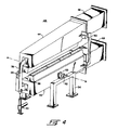
- FIG. 4 A perspective view of a steerable air bar assembly 24, according to one embodiment of the invention, is shown in Fig. 4.
- the assembly includes three adjustable air bars 38 supported by, and in air-receiving communication with, upper and lower headers 44 and 42.
- the combinations of the two lower air bars and the lower header, and the single upper air bar and upper header 44 will hereinafter be referred to as the lower and upper air bar/header assemblies, respectively).
- the upper and lower air bar/header assemblies are maintained in opposing spaced relation by spacer means comprising header carriage 36 and support member 50, and upper and lower headers 44 and 42 are each sealingly joined at one of their respective ends to upper and lower flexible air ducts 46 and 48.
- Header carriage 36 is connected at its lower edge to screw jack 40, and the lower air bar/header assembly engages on each side a pivot bearing 52, supported by a support member 54, by means of a connecting rod 53.
- screw jack 40 is adjusted up or down, the ends of both air bar/header assemblies adjacent screw jack 40 will correspondingly move up or down, as shown schematically in Fig. 5.
- a pivoting support means comprising pivot bearings 52 and connecting rods 53
- an angular adjustment means comprising screw jack 40
- the presence of header carriage 36 and support member 50 allows this movement to take place without the spatial relationship among the air bars being altered.
- This simultaneous adjustment of the orientation of both the upper and lower air bars is further facilitated by flexible air ducts 46 and 48, which allow a sealing relationship to be maintained between upper and lower headers 44 and 42 and the air supply, regardless of the position of the headers.
- flexible air ducts 46 and 48 One type of flexible air duct which may be used in the invention is described in U.S. Patent No. 4,480,859, the disclosure of which is incorporated herein by reference.
- FIG. 4 A preferred type of steerable air bar assembly of the invention is shown in Figs. 4 and 5.
- the invention is directed to any steerable air bar assembly comprising: i) a plurality of adjustable air bars, each having an elongated surface from which air may be discharged, said surface being in opposing relation to the running web, and each having two ends; ii) air supply means, in fluid communication with the air bars; and iii) adjustment means for altering the orientation of one or both of the elongated surfaces of the adjustable air bars with respect to the running web.
- one or both of the elongated surfaces is adjusted such that one or both of said surfaces rotate about an axis which is substantially parallel to the longitudinal centerline of the running web.
- the elongated surfaces may be rotated about an axis which is substantially perpendicular to the longitudinal centerline of the running web.
- the adjustment means may comprise other angular adjustment means and pivoting support means, such as cables, air cylinders attached to rods, and other conventional means for providing adjustable movement.
- the steerable air bar assembly would not include spacing means, e.g. the header carriage and support member described above. The spacing means would thus be eliminated, and separate adjustment means would be provided for each of the upper and lower air bar/header assemblies.
- the air bar/header assemblies may even in some instances be provided with adjustment means at each of their ends, as well as on both the upper and lower assemblies, such that each pair of air bar/header assemblies would have a total of four adjustment points.
- Adjustment of the orientation of the air bar surfaces, via the adjustment means may be accomplished manually by the dryer operator, by computer logic control, or by other means.
- the steerable air bar assembly may further comprise back pressure means, as described hereinabove.
- back pressure means on the steerable air bar(s) in the dryer may be in addition to or instead of such use on the fixed air bars as previously discussed.
- the air supply means may alternately comprise a plurality of headers, such as that shown in Fig. 6, each header comprising a standard header air supply duct 26 (e.g. a conventional header supply duct which is used to supply other air bars in the dryer) with sealing gasket 56 at one end, an extension 60 to the air supply duct, and a sealing flange 62 disposed between the extension and the sealing gasket, such that air delivery may be maintained during angular adjustments of the air bar/header assembly.
- a standard header air supply duct 26 e.g. a conventional header supply duct which is used to supply other air bars in the dryer
- header carriage 36 may be used in lieu of header carriage 36, provided that a fixed spatial relationship may be maintained between the upper and lower air bars.
- This type of air supply means is often preferred and would generally be necessary in a dryer such as the one shown in Fig. 1, as previously described.
- air bar Any type of air bar may be used in the present invention. Preferred types of air bars are described in U.S. Patent Nos. 3,549,070, 3,873,013, and 3,964,656, the disclosure of which is incorporated herein by reference. Furthermore, any desired number of air bars may be used in an air bar/header assembly, e.g. 50 or more.
- the steerable air bar assembly of the invention may be assembled using conventional methods, such as described in U.S. Patent No. 3,776,440, the disclosure of which is incorporated herein by reference.
- the position of the edge of the running web is monitored at one or more locations within the dryer, using conventional sensing means, such as fiber optics. Based on these measurements of the position of the web edge, the steerable air bars are adjusted periodically or continuously such that they provide a force which adjusts the web into a substantially straight path.
- computer-generated data may be used to predetermine the desired web path and the anticipated web position, and to compare these two positions. The steerable air bars may then be adjusted based upon that comparison to adjust the position of the web to the desired web path.
- back pressure means are placed on either fixed or steerable air bars at locations at which the web is expected to weave or drift. This also may be determined either experimentally, e.g. by conducting a dry run before running a given web through the dryer, or by the use of computer-generated data.
- the present invention relates to a method of guiding a web in a substantially straight path, e.g. as it passes through a web dryer apparatus.
- This method comprises driving a web through the dryer, floatingly supporting said web, sensing the position of the web edge, and providing a force responsive to said sensing to adjust the position of the web.
- the method comprises predicting the position of the web, rather than sensing said position, either based on computer-generated data or experimentally obtained data.
- the adjusting force may be provided by one or more steerable air bars, by back pressure means, or a combination thereof.
Abstract
Description
- This invention relates to web supporting apparatus and is more particularly concerned with a web supporting and guiding device for a web drying apparatus whereby a lengthwise moving web is floatingly supported and maintained in a straight path (i.e. centered with respect to the longitudinal centerline of the web) throughout the length of the web drying apparatus.
- In drying a moving web of paper, film, or the like, it is desirable that the web be contactlessly supported during the drying operation, to avoid damage to the web itself or to an ink or coating on the web. One common arrangement for contactlessly supporting a web comprises upper and lower sets of air bars extending along a substantially horizontal stretch of the web. Air issuing from the lower set of air bars floatingly supports the web, and air issuing from the upper set of air bars steadies the web to maintain it substantially straight and at a substantially constant distance from the air bars of both sets. The air blown from both sets of air bars is usually heated to expedite web drying, and typically the air bar array is inside an enclosure which is maintained at a slightly subatmospheric pressure by an exhaust blower that draws off the volatiles emanating from the web.
- Web dryers are used in many printing and graphics applications, such as the processing of photographic film, web offset printing, and other types of printing. In some applications, such as the processing of photographic film, web dryers having very long length, often as long as 150 feet, are commonly used. The greater the ratio of the length of the dryer to the width of the web (hereinafter referred to as the "length to width ratio"), the more susceptible the web is to minor forces that can cause the web to weave (move back and forth in a lateral direction) or shift (move laterally from the centerline and remain there). Also, some webs, such as thin plastic films, naturally take on a "banana-shaped" curve when they are laid flat, as in a dryer, thereby exacerbating the problems of web weave and shift. Web shifting and weaving may also result when the web tension is low, and when a lighter weight web, such as polyester film, is used.
- When the travelling web exits the drying apparatus it is generally wrapped around one or more rotating take-up members, such as chill rolls. When web weave or shift takes place as the web travels through the dryer, the web will correspondingly shift or weave as it contacts the rotating take-up member. Unless the web can be brought back to a straight orientation with respect to the centerline, the web will not wrap properly and the press must be shut down. This results in costly downtime and waste.
- Other problems may result from web weave or shift, e.g. if the web moves to one side or the other and stays in the new position it may not be centered on the press, resulting in an unacceptable product; if the web weave or shift is severe enough the web may break or tear, etc. These problems also force a shut-down of the press and thus a loss of valuable production time.
- In the past, attempts have been made to circumvent web weave and shift by guiding the web using contact systems such as a series of rollers. These systems are undesirable as they may cause damage to the ink or coating on the web, and are therefore inefficient in situations where there is a high length to width ratio.
- Thus it is desired to provide a means by which a web may be floatingly supported and urged in a substantially straight path at points in the dryer where it has a tendency to weave or shift as it travels through a web drying apparatus.
- The problems of the prior art have been solved by the present invention, which relates to an apparatus for handling and guiding a running web. More particularly, the present invention relates to an apparatus which both floatingly supports a web, and maintains the web in a substantially straight path as it travels through a dryer. The present invention further relates to a dryer comprising such web handling and guiding apparatus.
- The web handling and guiding apparatus of the present invention comprises a steerable air bar assembly comprising: i) one or more adjustable air bars, each having an elongated surface from which air may be discharged, said surface being in opposing relation to the running web, and each having two ends: ii) air supply means, in fluid communication with the air bars; and iii) adjustment means for altering the orientation of the elongated surfaces of the adjustable air bars such that the orientation of one or both of the surfaces is adjustable with respect to the running web. In a preferred embodiment, each said surface rotates about an axis which is substantially parallel to the longitudinal centerline of the running web. In addition, or alternatively, each said surface may rotate about an axis which is substantially perpendicular to the longitudinal centerline of the running web. Said steerable air bar assembly is positioned in a web dryer such that the web is guided through the dryer in a substantially straight path. One or more such steerable air bar assemblies can be used in a web dryer. The dryer can also include one or more fixed air bars.
- In a preferred embodiment of the invention, the apparatus further comprises in combination with the steerable air bar assembly, back pressure means for creating an opposing force to urge the web back to a substantially centered position. Said back pressure means preferably comprises one or more edge dams preferably disposed at or near the ends of one or more fixed air bars in the web dryer.
- In one embodiment of the invention the air supply means of the steerable air bar apparatus comprises a header which is sealingly joined at one end to a flexible air duct. The air bar is disposed adjacent the header such that air flows from the air duct into the header, and from the header into the air bar.
- In a further embodiment of the invention the orientation of the adjustable air bars is altered by adjustment means comprising a jack disposed at one end of the air bar assembly, and a pivoting support means disposed between the two ends.
- In its method aspects the present invention relates to a method of guiding a web in a substantially straight path, e.g. as it passes through a web dryer apparatus, using apparatus according to the invention.
- Fig. 1 is a vertical cross-sectional schematic view taken along the length of a web drying apparatus containing an apparatus for handling and guiding the web according to one. embodiment of the invention.
- Fig. 2 is a fragmentary, enlarged perspective view of an air bar including an edge dam.
- Fig. 3 is a schematic diagram showing the mechanism by which the edge dam alleviates web drift.
- Fig. 4 is a perspective view of the steerable air bar assembly according to one embodiment of the invention.
- Fig. 5 is a front view of the apparatus of a steerable air bar assembly illustrating the steering of the air bars.
- Fig. 6 is a side view of an alternate air supply means.
- A web drying apparatus for floatingly suspending a running web is shown in Fig. 1. Fig. 1 is illustrative of one type of web drying apparatus in which the guiding apparatus of the invention may be used. This apparatus includes an
elongated dryer housing 2 which is enclosed bytop 3,bottom 4, one side 5 and an opposite side 6. An inlet end 7 has a horizontal slot 8 through which web W enters. The opposite exit end is formed by theend wall 10 and a corresponding slot 11 therein through which web W exits. The dryer includes upper fixedair bars 15 and lowerfixed air bars 16; aheader frame 26 supporting and in air-delivering communication with the fixed air bars; and upper and lowerair supply ducts air supply ducts 28 which supply air to the headers. The upper and lower air bars are transversely positioned across the web, and are in staggered, spaced relationship along the web with respect to each other, such that they cause the web W to assume a conventional sine wave form, as shown in Fig. 1, when the dryer is in operation. - In order to illustrate the invention, the web drying apparatus shown in Fig. 1 has two
adjustable air bars 18 which each have two ends and which have back pressure means (as shown in Fig. 2 and discussed hereinbelow) disposed at at least one of each of their ends. The back pressure means serve to move the shifted web to its centered position, and are preferably present at least on those fixed air bars which are situated in areas of the dryer where the running web is prone to shifting. It is preferred that back pressure means be present on air bars which are situated approximately halfway along the length of the dryer, e.g. at 15 feet from the entrance to a 30 foot long dryer. It should be understood that as many of theair bars - The steerable air bar assembly of the invention (shown in Figs. 4 and 5) is shown schematically by
air bars 24 of Fig. 1. These steerable air bars are not engaged to the header and upper and lower air ducts in the same manner as the fixed air bars, but are separately connected to extensions fromheaders 26 which are joined to the headers by a sealing flange and sealing gasket, as shown in Fig. 6 and as described in detail hereinbelow, such that a flexible seal is created between the standard header and the adjustable air bar assembly. Like the back pressure means, the steerable air bar assemblies may be present in the web drying apparatus in any number, and may be substituted for any number of the fixed air bars. In fact, all, or a grouping of upper and lower fixed air bars could be replaced by a single steerable air bar assembly comprising a similar number of steerable air bars. When it is desired to use only a few steerable air bar assemblies it is again desirable to situate them at locations in the dryer where web shift is anticipated, such as the lengthwise midpoint of the dryer. - A fragmentary, enlarged view of an air bar comprising back pressure means according to one embodiment of the invention is shown in Fig. 2. An
edge dam 34 is shown mounted atend 30 ofair bar 18. In the embodiment shown in Fig. 2, the edge dam is bolted to the end of the air bar, however any conventional method could be used to mount the edge dam, or it could be integral with the air bar. Theedge dam 34 could also be located at points along the surface ofair bar 18, depending in part on the width of the web. The edge dam is preferably, as shown in Fig. 2, a T-shaped member, formed byelongated dam member 35, which, in the embodiment shown, extends above and approximately perpendicular to surface 33 ofair bar 18, and is supported in this position bysupport member 31.Support member 31 may be attached to the air bar by any suitable means, such asbolts 64 and airbar mounting bracket 66, as shown in Fig. 2. It is preferred that thedam member 35 have afin 17 disposed at each of its ends, such that the web does not have a tendency to snag on the entering and leaving edges of the edge dam. In one embodiment the lower edge ofdam member 35 is adjustable raised above surface 33 bysupport member 31, such that the distance between the lower edge and the surface may be from bout 5 cm to 60 cm. Vertical adjustment ofdam member 35 provides a means for controlling the back pressure force, by allowing a portion of the escaping air to be relieved below the edge dam. This embodiment is typically used in applications where nozzle velocities are high, e.g. from 10,000 to 16,000 fpm, causing very high back pressure. In another embodiment of the invention, for use with lower nozzle velocities,dam member 35 could be fixed, with its lower edge close to or in contact with the surface of the air bar. It is generally preferred in this embodiment that the lower edge of the dam member be in intimate, sealing contact with the surface of the air bar.Dam member 35, withfins 17, is also preferably of a length such that each end of the elongated member is approximately aligned with the correspondingair bar slot 32. - Although this configuration is preferred for the edge dam, any means may be used by which creates a back pressure against the web edge when the air bar is in use. This phenomenon is illustrated schematically in Fig. 3. In frame 1, one edge of web W approaches the
edge dam 34 during web weave as the web passes over theair bar 30. Inframe 2, theedge dam 34 creates a back pressure against web W, urging it back towards its initial path inframe 3. It is preferred that the back pressure means also be able to provide mechanical resistance against the web, should the air back pressure prove insufficient to return the web to its path. Thus if the web continued to travel toward theedge dam 34 inframe 2, it would eventually physically contact the edge dam and be forced back to its initial path. - Back pressure means may be disposed at either one or both ends of the air bar. It is generally preferred that back pressure means be disposed at both ends of the air bar, as it is usually difficult to predict in which direction the web will shift as it travels through the dryer. However, if the direction of web shift is known, then back pressure means may be placed only on the end of the air bar toward which the web will shift.
- A perspective view of a steerable
air bar assembly 24, according to one embodiment of the invention, is shown in Fig. 4. In this embodiment, the assembly includes three adjustable air bars 38 supported by, and in air-receiving communication with, upper andlower headers upper header 44 will hereinafter be referred to as the lower and upper air bar/header assemblies, respectively). The upper and lower air bar/header assemblies are maintained in opposing spaced relation by spacer means comprisingheader carriage 36 andsupport member 50, and upper andlower headers flexible air ducts Header carriage 36 is connected at its lower edge to screwjack 40, and the lower air bar/header assembly engages on each side a pivot bearing 52, supported by asupport member 54, by means of a connectingrod 53. Thus, whenscrew jack 40 is adjusted up or down, the ends of both air bar/header assembliesadjacent screw jack 40 will correspondingly move up or down, as shown schematically in Fig. 5. The angular adjustment of the air bar/header assemblies is thus facilitated by a pivoting support means, comprisingpivot bearings 52 and connectingrods 53, and an angular adjustment means, comprisingscrew jack 40, which allow the air bar/header assemblies to be rotated about an axis A which is substantially parallel to the longitudinal centerline of the running web, while being prevented from translational or rotational movement in any other plane. The presence ofheader carriage 36 andsupport member 50, allows this movement to take place without the spatial relationship among the air bars being altered. This simultaneous adjustment of the orientation of both the upper and lower air bars is further facilitated byflexible air ducts lower headers - A preferred type of steerable air bar assembly of the invention is shown in Figs. 4 and 5. However, in its broad aspects the invention is directed to any steerable air bar assembly comprising: i) a plurality of adjustable air bars, each having an elongated surface from which air may be discharged, said surface being in opposing relation to the running web, and each having two ends; ii) air supply means, in fluid communication with the air bars; and iii) adjustment means for altering the orientation of one or both of the elongated surfaces of the adjustable air bars with respect to the running web. In a preferred embodiment, one or both of the elongated surfaces is adjusted such that one or both of said surfaces rotate about an axis which is substantially parallel to the longitudinal centerline of the running web. Alternatively or additionally, the elongated surfaces may be rotated about an axis which is substantially perpendicular to the longitudinal centerline of the running web. In alternate embodiments of the invention, the adjustment means may comprise other angular adjustment means and pivoting support means, such as cables, air cylinders attached to rods, and other conventional means for providing adjustable movement. Additionally, in some applications it may be desirable to adjust the orientation of the upper and lower air bar/header assemblies individually. In these applications, the steerable air bar assembly would not include spacing means, e.g. the header carriage and support member described above. The spacing means would thus be eliminated, and separate adjustment means would be provided for each of the upper and lower air bar/header assemblies. The air bar/header assemblies may even in some instances be provided with adjustment means at each of their ends, as well as on both the upper and lower assemblies, such that each pair of air bar/header assemblies would have a total of four adjustment points.
- Adjustment of the orientation of the air bar surfaces, via the adjustment means, may be accomplished manually by the dryer operator, by computer logic control, or by other means.
- In a further embodiment of the invention, the steerable air bar assembly may further comprise back pressure means, as described hereinabove. The use of back pressure means on the steerable air bar(s) in the dryer may be in addition to or instead of such use on the fixed air bars as previously discussed.
- The air supply means may alternately comprise a plurality of headers, such as that shown in Fig. 6, each header comprising a standard header air supply duct 26 (e.g. a conventional header supply duct which is used to supply other air bars in the dryer) with sealing
gasket 56 at one end, anextension 60 to the air supply duct, and a sealingflange 62 disposed between the extension and the sealing gasket, such that air delivery may be maintained during angular adjustments of the air bar/header assembly. As shown in Fig. 6, adjustable air bars 18 are in air-receiving communication withextension 60, while fixed air bars 16 are in air-receiving communication with the standardheader air duct 26. Additionally, other spacing means may be used in lieu ofheader carriage 36, provided that a fixed spatial relationship may be maintained between the upper and lower air bars. This type of air supply means is often preferred and would generally be necessary in a dryer such as the one shown in Fig. 1, as previously described. - Any type of air bar may be used in the present invention. Preferred types of air bars are described in U.S. Patent Nos. 3,549,070, 3,873,013, and 3,964,656, the disclosure of which is incorporated herein by reference. Furthermore, any desired number of air bars may be used in an air bar/header assembly, e.g. 50 or more.
- The steerable air bar assembly of the invention may be assembled using conventional methods, such as described in U.S. Patent No. 3,776,440, the disclosure of which is incorporated herein by reference.
- In practice, the position of the edge of the running web is monitored at one or more locations within the dryer, using conventional sensing means, such as fiber optics. Based on these measurements of the position of the web edge, the steerable air bars are adjusted periodically or continuously such that they provide a force which adjusts the web into a substantially straight path. Alternatively, instead of sensing the position of the web as it travels through the dryer, computer-generated data may be used to predetermine the desired web path and the anticipated web position, and to compare these two positions. The steerable air bars may then be adjusted based upon that comparison to adjust the position of the web to the desired web path. As mentioned hereinabove, back pressure means are placed on either fixed or steerable air bars at locations at which the web is expected to weave or drift. This also may be determined either experimentally, e.g. by conducting a dry run before running a given web through the dryer, or by the use of computer-generated data.
- Thus, in its method aspects the present invention relates to a method of guiding a web in a substantially straight path, e.g. as it passes through a web dryer apparatus. This method comprises driving a web through the dryer, floatingly supporting said web, sensing the position of the web edge, and providing a force responsive to said sensing to adjust the position of the web. In an alternate embodiment of the invention, the method comprises predicting the position of the web, rather than sensing said position, either based on computer-generated data or experimentally obtained data. The adjusting force may be provided by one or more steerable air bars, by back pressure means, or a combination thereof.
- While preferred embodiments of the invention have been described herein, other variations and modifications may be practiced by those skilled in the art without departing form the spirit and scope of the invention.
Claims (21)
- Apparatus for guiding a web comprising a steerable air bar assembly comprising:a) one or more air bars (42), each having two ends and an elongated surface from which air may be discharged, the surface being in opposing relation to the web; andb) air supplying means, in communication with said air bars for supplying air to said air bars; characterised byc) adjustment means (40) for altering the orientation of the elongated surfaces of the air bars with respect to the web.
- An apparatus according to claim 1 wherein the orientation of said elongated surfaces is adjusted such that each said surface rotates about an axis which is either substantially parallel to, or substantially perpendicular to, the longitudinal centerline of the web.
- An apparatus according to claim 1 or 2, wherein the air supply means comprises a plurality of headers and a flexible duct sealingly joined to each of said headers.
- An apparatus according to claim 1 or 2, wherein the air supply means comprises a plurality of headers each header comprising a standard header air supply duct (26) having a sealing gasket (56) at one end, an extension (60) to the air supply duct, and a sealing flange (62) disposed between and in intimate contact with the extension and the sealing gasket, such that air delivery may be maintained during angular adjustments of the air bar and header.
- An apparatus according to claim 3 or 4, wherein said headers are in air-delivering communication with said adjustable air bars.
- An apparatus according to any one of claims 1 to 5, wherein the adjustment means comprises a jack, preferably a screw jack, and a pivoting support means (53) associated with the assembly.
- An apparatus according to any one of claims 1 to 6, comprising at least three said adjustable air bars (18).
- An apparatus according to any one of claims 1 to 6, wherein at least two said adjustable air bars (42,44) are situated in opposing spaced relation, such that the web passes between the two air bars.
- An apparatus according to claim 7 or 8, further comprising at least one spacing means (36;50) such that a fixed spatial relationship is maintained between said adjustable air bars (42,44).
- An apparatus according to claim 9, wherein said spacing means comprises at least one header carriage (36).
- Apparatus according to any one of claims 1 to 10, further comprising:d) a plurality of fixed air bars (18), each having an elongated surface from which air may be discharged; back pressure means (34) disposed above each of said elongated surfaces; said fixed air bars (18) being positioned in spaced relation to said adjustable air bars (24) along the length of the running web such that the running web is guided between said fixed and said steerable air bars in a substantially straight path.
- Apparatus according to claim 11, wherein said elongated surfaces of the fixed air bars are oriented substantially perpendicular to the longitudinal centerline of the web.
- Apparatus according to any one of claims 1 to 12, further comprising back pressure means associated with each of the adjustable air bar elongated surfaces.
- Apparatus according to any one of claims 11 to 13, wherein said back pressure means comprises at least one edge dam (34), preferably formed as a T-shaped member (31, 35) comprising an elongated dam member (35) and a support member (31).
- Apparatus according to claim 14, wherein said elongated dam member (35) extends above and approximately perpendicular to the fixed air bar elongated surface and is supported in this position by said support member (31), which is attached to the air bar by attachment means (64).
- Apparatus according to claim 14 or 15, wherein at least one of said fixed air bars (18) has more than one edge dam.
- A method of guiding a web in a substantially straight path as it passes through a web dryer apparatus, comprising the steps of:a) driving said web through the dryer while floatingly supporting said web; characterised byb) sensing the position of the web edge; andc) providing a force responsive to said sensing to adjust the position of the web.
- A method according to claim 17 wherein said force is provided by back pressure means, preferably an edge dam.
- A method according to claim 17 or 18 wherein said force is provided by one or more steerable air bar assemblies.
- A method according to any one of claims 17 to 19, comprising the steps of:-a) predetermining the desired web path;b) predetermining the anticipated position of the web edge;c) comparing the results of said predeterminations of steps (a) and (b); andd) providing said force based upon said comparison to adjust the position of the web to said desired web path.
- A method according to any one of claims 17 to 20 comprising floatingly supporting said web by providing cushions of air at various points in a dryer enclosure through a plurality of air bars; and adjusting the position of the web by altering the orientation of at least some (24) of said air bars with respect to said web.
Applications Claiming Priority (2)
| Application Number | Priority Date | Filing Date | Title |
|---|---|---|---|
| US46483190A | 1990-01-16 | 1990-01-16 | |
| US464831 | 1990-01-16 |
Publications (3)
| Publication Number | Publication Date |
|---|---|
| EP0441484A2 true EP0441484A2 (en) | 1991-08-14 |
| EP0441484A3 EP0441484A3 (en) | 1992-05-27 |
| EP0441484B1 EP0441484B1 (en) | 1996-05-22 |
Family
ID=23845415
Family Applications (1)
| Application Number | Title | Priority Date | Filing Date |
|---|---|---|---|
| EP19910300308 Expired - Lifetime EP0441484B1 (en) | 1990-01-16 | 1991-01-16 | Method of guiding a web through a dryer and apparatus for carrying out the method |
Country Status (4)
| Country | Link |
|---|---|
| EP (1) | EP0441484B1 (en) |
| JP (1) | JP3012359B2 (en) |
| CA (1) | CA2033883C (en) |
| DE (1) | DE69119619T2 (en) |
Cited By (3)
| Publication number | Priority date | Publication date | Assignee | Title |
|---|---|---|---|---|
| EP0513990A1 (en) * | 1991-05-16 | 1992-11-19 | W.R. Grace & Co.-Conn. | Moveable web slot |
| WO1997047934A1 (en) * | 1996-06-14 | 1997-12-18 | Koenig & Bauer Ag | Suspension drier |
| US10676282B2 (en) | 2017-03-24 | 2020-06-09 | Chugai Ro Co., Ltd. | Belt-shaped material conveying apparatus capable of correcting meandering |
Families Citing this family (3)
| Publication number | Priority date | Publication date | Assignee | Title |
|---|---|---|---|---|
| DE10257320B4 (en) * | 2002-12-06 | 2006-02-16 | Coatema Maschinenbau Gmbh | Channel system for the thermal treatment of coated webs |
| JP5084932B2 (en) * | 2010-06-24 | 2012-11-28 | パナソニック株式会社 | Levitation conveyance method and levitation conveyance apparatus |
| CN115183562B (en) * | 2022-08-25 | 2023-06-23 | 安徽省金正塑业有限公司 | Constant-temperature drying equipment for PVC sheet processing |
Citations (7)
| Publication number | Priority date | Publication date | Assignee | Title |
|---|---|---|---|---|
| GB905819A (en) * | 1960-02-24 | 1962-09-12 | Fritz Drabert | Drying device in particular for drying fabrics |
| DE1460544A1 (en) * | 1963-07-20 | 1969-03-27 | Dornbusch & Co | Method and device for the heat treatment of sensitive webs |
| EP0068272A1 (en) * | 1981-06-15 | 1983-01-05 | Daidotokushuko Kabushiki Kaisha | Apparatus for conveying strip material |
| JPS617161A (en) * | 1984-06-19 | 1986-01-13 | Chugai Ro Kogyo Kaisha Ltd | Floating/supporting device for stripe member |
| US4575952A (en) * | 1981-09-18 | 1986-03-18 | M.E.G., S.A. | Hot air dryer structure |
| DE3533273A1 (en) * | 1985-09-18 | 1987-03-26 | Ruckh Gerhard Maschf | Device for drying and shrinking textile mesh |
| US4787547A (en) * | 1987-06-11 | 1988-11-29 | Advance Systems, Inc. | Mounting means for air bars |
-
1991
- 1991-01-09 CA CA 2033883 patent/CA2033883C/en not_active Expired - Lifetime
- 1991-01-14 JP JP3131704A patent/JP3012359B2/en not_active Expired - Fee Related
- 1991-01-16 EP EP19910300308 patent/EP0441484B1/en not_active Expired - Lifetime
- 1991-01-16 DE DE1991619619 patent/DE69119619T2/en not_active Expired - Lifetime
Patent Citations (7)
| Publication number | Priority date | Publication date | Assignee | Title |
|---|---|---|---|---|
| GB905819A (en) * | 1960-02-24 | 1962-09-12 | Fritz Drabert | Drying device in particular for drying fabrics |
| DE1460544A1 (en) * | 1963-07-20 | 1969-03-27 | Dornbusch & Co | Method and device for the heat treatment of sensitive webs |
| EP0068272A1 (en) * | 1981-06-15 | 1983-01-05 | Daidotokushuko Kabushiki Kaisha | Apparatus for conveying strip material |
| US4575952A (en) * | 1981-09-18 | 1986-03-18 | M.E.G., S.A. | Hot air dryer structure |
| JPS617161A (en) * | 1984-06-19 | 1986-01-13 | Chugai Ro Kogyo Kaisha Ltd | Floating/supporting device for stripe member |
| DE3533273A1 (en) * | 1985-09-18 | 1987-03-26 | Ruckh Gerhard Maschf | Device for drying and shrinking textile mesh |
| US4787547A (en) * | 1987-06-11 | 1988-11-29 | Advance Systems, Inc. | Mounting means for air bars |
Non-Patent Citations (2)
| Title |
|---|
| PATENT ABSTRACTS OF JAPAN vol. 10, no. 153 (M-484)(2209) 3 June 1986 & JP-A-61 007 161 ( CHIYUUGAI RO KOGYO K.K. ) 13 January 1986 * |
| RESEARCH DISCLOSURE. no. 252, April 1985, EMSWORTH, HAMPSHIRE, GB page 175; 'drying oven' * |
Cited By (4)
| Publication number | Priority date | Publication date | Assignee | Title |
|---|---|---|---|---|
| EP0513990A1 (en) * | 1991-05-16 | 1992-11-19 | W.R. Grace & Co.-Conn. | Moveable web slot |
| WO1997047934A1 (en) * | 1996-06-14 | 1997-12-18 | Koenig & Bauer Ag | Suspension drier |
| US5921451A (en) * | 1996-06-14 | 1999-07-13 | Koenig & Bauer-Aktiengesellschaft | Dryer assembly for supporting and positioning a web |
| US10676282B2 (en) | 2017-03-24 | 2020-06-09 | Chugai Ro Co., Ltd. | Belt-shaped material conveying apparatus capable of correcting meandering |
Also Published As
| Publication number | Publication date |
|---|---|
| DE69119619D1 (en) | 1996-06-27 |
| CA2033883C (en) | 2001-09-04 |
| CA2033883A1 (en) | 1991-07-17 |
| DE69119619T2 (en) | 1996-10-31 |
| EP0441484B1 (en) | 1996-05-22 |
| JP3012359B2 (en) | 2000-02-21 |
| JPH04226249A (en) | 1992-08-14 |
| EP0441484A3 (en) | 1992-05-27 |
Similar Documents
| Publication | Publication Date | Title |
|---|---|---|
| EP0003414B1 (en) | Float treatment apparatus | |
| US4833794A (en) | Dryer apparatus for floating a running web and having baffle means for spent return air | |
| US5416992A (en) | Apparatus for spreading rectangular cloth | |
| US5152080A (en) | Steerable air bar/edge dam apparatus | |
| US3448907A (en) | Web positioner bar | |
| SE461921B (en) | PROCEDURE AND DEVICE FOR CUTTING A APPLICATION TAPE FOR A PAPER COAT | |
| EP1337798B1 (en) | Non-contact floating device for turning a floating web-private | |
| JPH0356914B2 (en) | ||
| JPS599456B2 (en) | Paper web overhang and guide device | |
| EP0441484A2 (en) | Method of guiding a web through a dryer and apparatus for carrying out the method | |
| GB2132324A (en) | Apparatus for treatment of a web of material by gaseous medium | |
| FI82095C (en) | FOERFARANDE OCH ANORDNING I CYLINDERTORKEN AV EN PAPPERSMASKIN. | |
| CA2042320A1 (en) | Single wire dryer group with adjustable reversing rolls | |
| US6397495B1 (en) | Web steering air flotation device for printing equipment | |
| EP0513990B1 (en) | Moveable web slot | |
| SE504747C2 (en) | Scanning device for scanning a physical property of a fiber web | |
| US5921451A (en) | Dryer assembly for supporting and positioning a web | |
| EP0675064B1 (en) | Air foil wing extension for an air turn | |
| EP0192429B1 (en) | Hydrostatic film support | |
| CA2063903A1 (en) | Center pivot air turn web steering assembly | |
| CN1627027A (en) | Apparatus for the heat treatment of a textile web | |
| US9365976B2 (en) | Endless belt changing apparatus and method | |
| JPH0672601A (en) | Floater for noncontact conveyance | |
| FI81856B (en) | Blowing box |
Legal Events
| Date | Code | Title | Description |
|---|---|---|---|
| PUAI | Public reference made under article 153(3) epc to a published international application that has entered the european phase |
Free format text: ORIGINAL CODE: 0009012 |
|
| AK | Designated contracting states |
Kind code of ref document: A2 Designated state(s): DE FR GB IT |
|
| PUAL | Search report despatched |
Free format text: ORIGINAL CODE: 0009013 |
|
| AK | Designated contracting states |
Kind code of ref document: A3 Designated state(s): DE FR GB IT |
|
| 17P | Request for examination filed |
Effective date: 19921125 |
|
| 17Q | First examination report despatched |
Effective date: 19931008 |
|
| GRAH | Despatch of communication of intention to grant a patent |
Free format text: ORIGINAL CODE: EPIDOS IGRA |
|
| GRAA | (expected) grant |
Free format text: ORIGINAL CODE: 0009210 |
|
| AK | Designated contracting states |
Kind code of ref document: B1 Designated state(s): DE FR GB IT |
|
| ITF | It: translation for a ep patent filed |
Owner name: STUDIO CONS. BREVETTUALE S.R.L. |
|
| REF | Corresponds to: |
Ref document number: 69119619 Country of ref document: DE Date of ref document: 19960627 |
|
| ET | Fr: translation filed | ||
| PLBE | No opposition filed within time limit |
Free format text: ORIGINAL CODE: 0009261 |
|
| STAA | Information on the status of an ep patent application or granted ep patent |
Free format text: STATUS: NO OPPOSITION FILED WITHIN TIME LIMIT |
|
| 26N | No opposition filed | ||
| REG | Reference to a national code |
Ref country code: FR Ref legal event code: TP |
|
| REG | Reference to a national code |
Ref country code: GB Ref legal event code: 732E |
|
| REG | Reference to a national code |
Ref country code: GB Ref legal event code: IF02 |
|
| PG25 | Lapsed in a contracting state [announced via postgrant information from national office to epo] |
Ref country code: IT Free format text: LAPSE BECAUSE OF NON-PAYMENT OF DUE FEES;WARNING: LAPSES OF ITALIAN PATENTS WITH EFFECTIVE DATE BEFORE 2007 MAY HAVE OCCURRED AT ANY TIME BEFORE 2007. THE CORRECT EFFECTIVE DATE MAY BE DIFFERENT FROM THE ONE RECORDED. Effective date: 20050116 |
|
| PGFP | Annual fee paid to national office [announced via postgrant information from national office to epo] |
Ref country code: FR Payment date: 20100208 Year of fee payment: 20 |
|
| PGFP | Annual fee paid to national office [announced via postgrant information from national office to epo] |
Ref country code: GB Payment date: 20100113 Year of fee payment: 20 Ref country code: DE Payment date: 20100114 Year of fee payment: 20 |
|
| REG | Reference to a national code |
Ref country code: GB Ref legal event code: PE20 Expiry date: 20110115 |
|
| PG25 | Lapsed in a contracting state [announced via postgrant information from national office to epo] |
Ref country code: GB Free format text: LAPSE BECAUSE OF EXPIRATION OF PROTECTION Effective date: 20110115 |
|
| PG25 | Lapsed in a contracting state [announced via postgrant information from national office to epo] |
Ref country code: DE Free format text: LAPSE BECAUSE OF EXPIRATION OF PROTECTION Effective date: 20110116 |