EP0441542A1 - Combustor and method of combusting fuel - Google Patents
Combustor and method of combusting fuel Download PDFInfo
- Publication number
- EP0441542A1 EP0441542A1 EP91300808A EP91300808A EP0441542A1 EP 0441542 A1 EP0441542 A1 EP 0441542A1 EP 91300808 A EP91300808 A EP 91300808A EP 91300808 A EP91300808 A EP 91300808A EP 0441542 A1 EP0441542 A1 EP 0441542A1
- Authority
- EP
- European Patent Office
- Prior art keywords
- passageway
- combustor
- venturi
- combustion
- air
- Prior art date
- Legal status (The legal status is an assumption and is not a legal conclusion. Google has not performed a legal analysis and makes no representation as to the accuracy of the status listed.)
- Granted
Links
Images
Classifications
-
- F—MECHANICAL ENGINEERING; LIGHTING; HEATING; WEAPONS; BLASTING
- F23—COMBUSTION APPARATUS; COMBUSTION PROCESSES
- F23R—GENERATING COMBUSTION PRODUCTS OF HIGH PRESSURE OR HIGH VELOCITY, e.g. GAS-TURBINE COMBUSTION CHAMBERS
- F23R3/00—Continuous combustion chambers using liquid or gaseous fuel
- F23R3/28—Continuous combustion chambers using liquid or gaseous fuel characterised by the fuel supply
- F23R3/30—Continuous combustion chambers using liquid or gaseous fuel characterised by the fuel supply comprising fuel prevapourising devices
-
- F—MECHANICAL ENGINEERING; LIGHTING; HEATING; WEAPONS; BLASTING
- F23—COMBUSTION APPARATUS; COMBUSTION PROCESSES
- F23R—GENERATING COMBUSTION PRODUCTS OF HIGH PRESSURE OR HIGH VELOCITY, e.g. GAS-TURBINE COMBUSTION CHAMBERS
- F23R3/00—Continuous combustion chambers using liquid or gaseous fuel
- F23R3/02—Continuous combustion chambers using liquid or gaseous fuel characterised by the air-flow or gas-flow configuration
- F23R3/04—Air inlet arrangements
-
- F—MECHANICAL ENGINEERING; LIGHTING; HEATING; WEAPONS; BLASTING
- F23—COMBUSTION APPARATUS; COMBUSTION PROCESSES
- F23R—GENERATING COMBUSTION PRODUCTS OF HIGH PRESSURE OR HIGH VELOCITY, e.g. GAS-TURBINE COMBUSTION CHAMBERS
- F23R3/00—Continuous combustion chambers using liquid or gaseous fuel
- F23R3/002—Wall structures
-
- F—MECHANICAL ENGINEERING; LIGHTING; HEATING; WEAPONS; BLASTING
- F23—COMBUSTION APPARATUS; COMBUSTION PROCESSES
- F23R—GENERATING COMBUSTION PRODUCTS OF HIGH PRESSURE OR HIGH VELOCITY, e.g. GAS-TURBINE COMBUSTION CHAMBERS
- F23R3/00—Continuous combustion chambers using liquid or gaseous fuel
- F23R3/42—Continuous combustion chambers using liquid or gaseous fuel characterised by the arrangement or form of the flame tubes or combustion chambers
Definitions
- the present invention relates to combustor and method of combusting fuel.
- the combustor may be used in for example a gas turbine.
- a venturi configuration can be used to stabilize the combustion flame.
- lowered NO x emissions are achieved by lowering peak flame temperatures through the burning of a lean, uniform mixture of fuel and air. Uniformity is achieved by premixing fuel and air in the combustor upstream of the venturi and then firing the mixture downstream of the venturi sharp-edged throat.
- the venturi configuration by virtue of accelerating the flow preceding the throat, is intended to keep the flame from flashing back into the premixing region.
- the nature of the flow adjacent the downstream wall of the venturi is a zone of separated flow and is believed to serve as a flame holding region. This flame holding region is required for continuous, stable, premixed fuel burning. Because the venturi walls bound a combustion flame, they must be cooled. This is accomplished with back side impingement air which then dumps into the combustion zone at the downstream end of the venturi.
- back side impingement air which then dumps into the combustion zone at the downstream end of the venturi.
- Premixed fuel combustion by its nature is very unstable.
- the unstable condition can lead to a situation in which the flame cannot be maintained, which is referred to as "blow-out". This is especially true as the fuel-air stoichiometry is decreased to just above the lean flammability limit, a condition that is required to achieve low levels of NO x emissions.
- the problem to be solved with the premixed dry low NO x combustor is to lean out the fuel-air mixture to reduce NO x while maintaining a stable flame at the desire operating temperature. Further, it is desirable to have stable premixed burning over a wide range in combustion temperature to allow for greater flexibility in operation of the gas turbine, and to increase the product life of turbine combustion systems.
- a combustor comprising : a premixing chamber for mixing fuel gas and air; a combustion chamber positioned downstream of said premixing chamber for the combustion of the premixed fuel gas and air and including a separated zone and a combustion zone downstream from said separated zone; a venturi positioned between said premixing chamber and said combustion chamber through which said premixed fuel gas and air pass to said combustion chamber; and a passageway for cooling gas flow extending axially along at least a significant portion of the downstream surface of said venturi in the region of said combustion chamber; said passageway positioned on the side of said venturi opposite that which said premixed fuel gas and air passes to said combustion chamber; and said passageway extending far enough dowstream in said combustion chamber to avoid significant backflow of said cooling gas into said separated zone after exiting said passageway.
- An illustrative embodiment of the invention as disclosed herein provides a dry, low nitric oxides emissions, combustor for use with a gas turbine, in which fuel gas and air are premixed and then fed through a venturi to the combustion chamber.
- the venturi is air cooled and includes a substantially cylindrical passage attached to the downstream throat of the venturi and extending into the combustion chamber, controlling reverse flow of the venturi cooling air into the separated region adjacent the venturi downstream wall and improving the stability of the premixed fuel burning operation.
- 10 and 11 are sections of an annular premixing chamber or individual chambers in which fuel gas and air are premixed.
- the fuel gas 12 which may, for example, be natural gas or other hydrocarbon vapor, is provided through fuel flow controller 14 to one or more fuel nozzles such as 16 and 17 in premixing chambers 10 and 11, respectively.
- fuel flow controller 14 to one or more fuel nozzles such as 16 and 17 in premixing chambers 10 and 11, respectively.
- a single axisymmetric fuel nozzle such as 16 and 17 may be used for each premix chamber.
- Air is introduced through one or more entry ports such as 18. The air is provided to ports 18 from the gas turbine compressor (not shown) under an elevated pressure of five to fifteen atmospheres.
- the premixed fuel and air is provided to the interior of the combustion chamber 22 through venturi 24 formed by angular walls 32 meeting at the constriction or constricted throat 30.
- the combustion chamber 22 is generally cylindrical in shape about combustor centerline 26 and enclosed by outer walls 28 and 29.
- venturi 24 causes the fuel-air mixture moving downstream in the direction of arrows 31 and 33 to accelerate as it flows through the constricted throat 30 to the combustion chamber 22.
- venturi wall, 32 is adjacent the combustion chamber 22, it is necessary to cool the wall with back side impingement air flowing along and through passageway or channel 36 bounded by the venturi walls 32 and generally parallel walls 33.
- the cooling air 23 may be provided from the turbine compressor (not shown) through the wall 33, at inlet 25, or alternatively through louvers in the wall as described in the aforesaid United States Patent Number 4,292,801.
- the cooling medium may also be, or include, steam or water mixed with the air.
- the bulk flow detachment is caused by the rapid increase in geometric area downstream of the venturi throat 30.
- the path of the venturi cooling dump flow in a combustor in which the downstream exit 36 is directly connected to the interior of the combustion chamber 22 was found to be the reverse flow shown by dotted flow lines and arrows 42. Subsequent actual "fired" testing of that dry low NO x system has shown that reducing the amount of venturi cooling air entering the separated zone improved the stability of the premixed fuel burning operation.
- the exit channel 36 is connected through the passageway 44 extending downstream from the exit channel and formed by a cylindrical wall 46 which is concentric with and within combustor wall 28 to form the passageway therebetween.
- the wall 46 since it is also adjacent to the combustion chamber 22, is provided with some cooling such as back side impingement air, film air, or fins such as 48, to transfer heat away from the wall.
- the wall 46 may be the combustor shroud wall which is adjacent to the combustion process.
- the length 49 of the passageway 44 is optimized for each combustor design although it is in general some 8 to 10 times the radial width of the venturi exit channel 36.
- One embodiment of the invention was on a combustor 20 having an internal diameter of 10 inches, a distance 47 of 3 inches axially from the constricted throat 30 of venturi 24 to the downstream exit 49 of the exit channel 36 of the venturi, a throat diameter 30 of 7 inches, and a 2 inch axial length 49 of the passageway 44 formed by cylindrical wall 46 and wall 28.
- the internal diameter of the combustor 20 was varied from 10-14 inches
- the distance 47 was varied from 3-5 inches
- the diameter of the throat 30 was varied from 7-9 inches
- the length of the passageway 44 was varied from 2-7 inches.
- the present combustor provides a passageway of significant and sufficient length to carry the venturi cooling gas flow further downstream. It is believed that the cooling gas dump should be at least beyond the mid region of the separated zone 54.
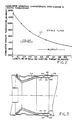
- FIG. 2 shows the effects of varying the length 49 of the passageway 44.
- the combustor exhaust temperatures in 0F are plotted on the Y axis and the ratio of the passageway 44 length/width are plotted on the X axis.
- the stable flame region is above the resultant plot or curve 57 while the cycling or unstable flame region is below the plot. It is to be noted that increasing the length/width ratio lowers the range of temperatures at which the combustor 20 provides a stable flame.
- FIG. 2 shows how the combustor exhaust temperature varies with changing the length of the venturi air dump 46, made dimensionless using the venturi diameter 30. Below the curve, the combustor begins to operate in a cyclic mode where the premixed combustion is unstable.
- the premixed fuel gas and air blows out As an example, if the dimensionless venturi air dump length is 0.25, the dry low No x combustor 20 can be operated stably at an exhaust temperature above 1900 degrees. Further, if the full load operating temperature is 2100 degrees, then the combustor can be operated in the premixed firing mode at partial load conditions corresponding to the range in exhaust temperature from 1900 to 2100 degrees. It is to be noted that the stable flame temperature may be lowered from in excess of 21000 F to less than 17000 F. This ability to maintain stable combustion over a wide range, including lower temperatures, has-achieved a desired reduction in the NO x and carbon monoxide (CO) emissions.
- CO carbon monoxide
- the benefits of the present combustor due to the improvement in the premixed operating mode of the dry low NO x combustor 20 are: (1) greater flexibility in operating the gas turbine because of a larger temperature range, including lower temperatures, over which the combustor is stable and can be fired in the premixed mode, (2) lowered resultant NO x emissions, (3) lowered CO emissions, (4) increased combustor lifetime and time between inspections due to lower system dynamic pressures, and (5) provision of a means of adjusting the combustor operation such that the emissions can be optimized for a given combustor nominal operating temperature.
- FIG. 3 shows an alternate embodiment of the present invention.
- the length of the passageway 44 is made adjustable to enable adjustable optimization of the present invention under variable operating conditions.
- a cylindrical sleeve 60 is slidably mounted closely within the passage to enable adjustment of the effective length of passageway 44. Because of the high temperatures and harsh environment of the interior of combustor 20 most installations may include a non-adjustable wall 46 which is designed for optimum operating characteristics.
- the adjustment mechanism shown schematically as controls 62 may be of any suitable type for the combustor 20 environment such as a rack and pinion mechanism or simply movement of the sleeve 60 by the control 62 moving within an axial slot 64 in wall 28, with control 62 being threaded fasteners to secure the sleeve in the desired location by screwing the fasteners tightly into the threaded bores 66 in the sleeve.
Abstract
Description
- The present invention relates to combustor and method of combusting fuel. The combustor may be used in for example a gas turbine.
- In recent years, gas turbine manufacturers have become increasingly concerned with pollutant emissions. Of particular concern has been the emissions of nitrogen oxides (NOx) because such oxides are a precursor to air pollution.
- It is known that NOx formation increases with increasing flame temperature and with increasing residence time. It is therefore theoretically possible to reduce NOx emissions by reducing flame temperature and/or the time at which the reacting gases remain at the peak temperatures. In practice, however, this is difficult to achieve because of the turbulent diffusion flame characteristics of present day gas turbine combustors. In such combustors, the combustion takes place in a thin layer surrounding either the evaporating liquid fuel droplets or the dispensing gaseous fuel jets at a fuel/air equivalence ratio near unity regardless of the overall reaction zone equivalence ratio. Since this is the condition which results in the highest flame temperature, relatively large amounts of NOx are produced.
- It is also known that the injection of significant amounts of water or steam can reduce NOx production so that the conventional combustors can meet the low NOx emission requirements. However, such injection also has many disadvantages including an increase in system complexity, an increase in operating costs due to the necessity for water treatment, and the degrading of other performance parameters.
- The problem of realizing low NOx emissions becomes even further complicated when it is necessary to meet other combustion design criteria. Among such criteria are those of good ignition qualities, good crossfiring capability, stability over the entire load range, low traverse number or flat exhaust temperature profile, long life and the ability to operate safely.
- Some of the factors which result in the formation of nitrogen oxides from fuel nitrogen and air nitrogen are known and efforts have been made to adapt various combustor operations in light of these factors. See, for example, United States Patent Numbers 3,958,413; 3,958,416; 3,946,553; and 4,420,929. The processes used heretofore, however, have either not been adaptable for use in a combustor for a stationary gas turbine or adequate for the reasons set forth below.
- A venturi configuration can be used to stabilize the combustion flame. In such arrangements, lowered NOx emissions are achieved by lowering peak flame temperatures through the burning of a lean, uniform mixture of fuel and air. Uniformity is achieved by premixing fuel and air in the combustor upstream of the venturi and then firing the mixture downstream of the venturi sharp-edged throat. The venturi configuration, by virtue of accelerating the flow preceding the throat, is intended to keep the flame from flashing back into the premixing region. Further, the nature of the flow adjacent the downstream wall of the venturi is a zone of separated flow and is believed to serve as a flame holding region. This flame holding region is required for continuous, stable, premixed fuel burning. Because the venturi walls bound a combustion flame, they must be cooled. This is accomplished with back side impingement air which then dumps into the combustion zone at the downstream end of the venturi. However, such arrangements have not been entirely satisfactory.
- United States Patent number 4,292,801 of Wilkes and Hilt, and which is hereby incorporated by reference, describes a gas turbine combustor which has an upstream combustion chamber and a downstream combustion chamber separated by a venturi throat or constriction region. Other patent applications directed at reducing the NOx emissions include European Patent Applications EP-A-273126 (15DV-2910) and EP-A-269824 (51DV-2903), which are hereby incorporated by reference. EP-A-269824 (51DV-2903) is directed at premixed fuel and air combustor arrangements including a venturi.
- Premixed fuel combustion by its nature is very unstable. The unstable condition can lead to a situation in which the flame cannot be maintained, which is referred to as "blow-out". This is especially true as the fuel-air stoichiometry is decreased to just above the lean flammability limit, a condition that is required to achieve low levels of NOx emissions. The problem to be solved with the premixed dry low NOx combustor is to lean out the fuel-air mixture to reduce NOx while maintaining a stable flame at the desire operating temperature. Further, it is desirable to have stable premixed burning over a wide range in combustion temperature to allow for greater flexibility in operation of the gas turbine, and to increase the product life of turbine combustion systems.
- According to one aspect of the present invention, there is provided a combustor comprising :
a premixing chamber for mixing fuel gas and air;
a combustion chamber positioned downstream of said premixing chamber for the combustion of the premixed fuel gas and air and including a separated zone and a combustion zone downstream from said separated zone;
a venturi positioned between said premixing chamber and said combustion chamber through which said premixed fuel gas and air pass to said combustion chamber; and
a passageway for cooling gas flow extending axially along at least a significant portion of the downstream surface of said venturi in the region of said combustion chamber;
said passageway positioned on the side of said venturi opposite that which said premixed fuel gas and air passes to said combustion chamber; and
said passageway extending far enough dowstream in said combustion chamber to avoid significant backflow of said cooling gas into said separated zone after exiting said passageway. - An illustrative embodiment of the invention as disclosed herein provides a dry, low nitric oxides emissions, combustor for use with a gas turbine, in which fuel gas and air are premixed and then fed through a venturi to the combustion chamber. The venturi is air cooled and includes a substantially cylindrical passage attached to the downstream throat of the venturi and extending into the combustion chamber, controlling reverse flow of the venturi cooling air into the separated region adjacent the venturi downstream wall and improving the stability of the premixed fuel burning operation.
- For a better understanding of the present invention, reference will now be made, by way of example, to the accompanying drawings, in which:
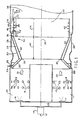
- FIG. 1 is a simplified representation of a cross section of an illustrative gas turbine combustion system incorporating the present invention;
- FIG. 2 is a plot of the improved operating characteristics realized through use of the present combustion system;
- FIG. 3 is a partial cross section, shown in reduced size, of a portion of FIG 1 incorporating an alternative embodiment of the present invention.
- Referring first to FIG. 1, 10 and 11 are sections of an annular premixing chamber or individual chambers in which fuel gas and air are premixed. The
fuel gas 12, which may, for example, be natural gas or other hydrocarbon vapor, is provided through fuel flow controller 14 to one or more fuel nozzles such as 16 and 17 inpremixing chambers 10 and 11, respectively. In accordance with the above referenced United States Patents and European patent applications, there may be a plurality of premixing chambers arranged circumferentially around the upstream end of combustor. While 2combustion chambers 10 and 11 are shown in FIG. 1, there can be any suitable number of combustion chambers. A single axisymmetric fuel nozzle such as 16 and 17 may be used for each premix chamber. Air is introduced through one or more entry ports such as 18. The air is provided toports 18 from the gas turbine compressor (not shown) under an elevated pressure of five to fifteen atmospheres. - The premixed fuel and air is provided to the interior of the
combustion chamber 22 throughventuri 24 formed byangular walls 32 meeting at the constriction or constrictedthroat 30. Thecombustion chamber 22 is generally cylindrical in shape aboutcombustor centerline 26 and enclosed byouter walls - The
venturi 24 causes the fuel-air mixture moving downstream in the direction ofarrows constricted throat 30 to thecombustion chamber 22. - Because the venturi wall, 32 is adjacent the
combustion chamber 22, it is necessary to cool the wall with back side impingement air flowing along and through passageway orchannel 36 bounded by theventuri walls 32 and generallyparallel walls 33. Thecooling air 23 may be provided from the turbine compressor (not shown) through thewall 33, atinlet 25, or alternatively through louvers in the wall as described in the aforesaid United States Patent Number 4,292,801. The cooling medium may also be, or include, steam or water mixed with the air. - Arrangements which have dumped the cooling air from the
passageway 36 of theventuri 24 have not proven to be as stable in operation over a wide a temperature range as desired, and/or have not provided the optimum low NOx emissions desired. In studying this during the development of an improved low NOx combustor 20, we have observed with flow visualization techniques on a full scale plexiglass model of the combustor, that the venturi cooling air dumping into thecombustion zone 22, proceeds to "reverse" flow into the separated region or zone adjacent the venturi wall in thedownstream area 37. The separated zone is characterized by a detachment of the bulk flow fromwalls 32 with a small amount of air, and burned and unburned fuel recirculating in the area bounded by the bulk flow andwalls 32. The bulk flow detachment is caused by the rapid increase in geometric area downstream of theventuri throat 30. The path of the venturi cooling dump flow in a combustor in which thedownstream exit 36 is directly connected to the interior of thecombustion chamber 22 was found to be the reverse flow shown by dotted flow lines andarrows 42. Subsequent actual "fired" testing of that dry low NOx system has shown that reducing the amount of venturi cooling air entering the separated zone improved the stability of the premixed fuel burning operation. - Thus, we have proven that the reverse flow cooling air adversely affects the stability of such venturi combustion systems.
- Through further experimentation it was determined that the performance of the combustor could be improved greatly and unexpectedly by providing a controlled cooling air flow dump downstream from the
venturi wall 32 toward the combustion zone in the interior of the combustor, and furthermore that this could be accomplished with relatively simple hardware. - Referring again to FIG. 1, the
exit channel 36 is connected through thepassageway 44 extending downstream from the exit channel and formed by acylindrical wall 46 which is concentric with and withincombustor wall 28 to form the passageway therebetween. Thewall 46, since it is also adjacent to thecombustion chamber 22, is provided with some cooling such as back side impingement air, film air, or fins such as 48, to transfer heat away from the wall. Thewall 46 may be the combustor shroud wall which is adjacent to the combustion process. Thelength 49 of thepassageway 44 is optimized for each combustor design although it is in general some 8 to 10 times the radial width of theventuri exit channel 36. One embodiment of the invention was on acombustor 20 having an internal diameter of 10 inches, adistance 47 of 3 inches axially from the constrictedthroat 30 ofventuri 24 to thedownstream exit 49 of theexit channel 36 of the venturi, athroat diameter 30 of 7 inches, and a 2 inchaxial length 49 of thepassageway 44 formed bycylindrical wall 46 andwall 28. On other embodiments, the internal diameter of thecombustor 20 was varied from 10-14 inches, thedistance 47 was varied from 3-5 inches, the diameter of thethroat 30 was varied from 7-9 inches, and the length of thepassageway 44 was varied from 2-7 inches. With this arrangement, thedump cooling air 52 from theventuri 24 was found to be mostly in the downstream flow in the combustion chamber as shown by thearrows 52 with only asmall reverse flow 55. We have found that this provides significant benefits as described in more detail below. - However, prior to the actual combustor testing and flow visualization testing on a full scale plexiglass model, it was thought that the venturi cooling air flow through
passageway 44 exited to thecombustion zone 58 along thewall 28 and did not in its entirety, or substantial entirety, flow upstream against the flow of fuel gas and air into the separatedzone 54 as shown by thearrows 42. Contrary to that existing belief, we now believe that the low pressure zone in the separated region or separatedzone 54 adjacent to the venturi downstream wall 32 (due to high velocity combustion gases created by the vena contracta of the venturi throat 30) induces the venturi cooling air, which was dumped at the downstream edge of thepassageway 36, to flow backwards upstream into the separatedzone 54. - The present combustor provides a passageway of significant and sufficient length to carry the venturi cooling gas flow further downstream. It is believed that the cooling gas dump should be at least beyond the mid region of the separated
zone 54. - Subsequent testing on full pressure, fired combustion equipment with varying length passageways led to the discovery that controlling the amount of cooling fluid entering the separated
zone 54 significantly improved the stability of a premixed fuel-air combustor. The improved results included a significant increase in the temperature range over which premixed operation is possible, and, in addition, the ability to operate thecombustor 20 with lower combustion system dynamic pressures. It is inferred from temperature measurements of a full pressure, fired combustion system without thepassageway 44 that the venturi cooling air significantly cools and dilutes the combustion gases recirculating in the separatedzone 54 resulting in reducing the flame holding stability of this region. - FIG. 2 shows the effects of varying the
length 49 of thepassageway 44. Referring to FIG. 2, the combustor exhaust temperatures in ⁰F are plotted on the Y axis and the ratio of thepassageway 44 length/width are plotted on the X axis. The stable flame region is above the resultant plot orcurve 57 while the cycling or unstable flame region is below the plot. It is to be noted that increasing the length/width ratio lowers the range of temperatures at which thecombustor 20 provides a stable flame. FIG. 2 shows how the combustor exhaust temperature varies with changing the length of theventuri air dump 46, made dimensionless using theventuri diameter 30. Below the curve, the combustor begins to operate in a cyclic mode where the premixed combustion is unstable. Below 1600 degrees the premixed fuel gas and air blows out. As an example, if the dimensionless venturi air dump length is 0.25, the dry low Nox combustor 20 can be operated stably at an exhaust temperature above 1900 degrees. Further, if the full load operating temperature is 2100 degrees, then the combustor can be operated in the premixed firing mode at partial load conditions corresponding to the range in exhaust temperature from 1900 to 2100 degrees. It is to be noted that the stable flame temperature may be lowered from in excess of 2100⁰ F to less than 1700⁰ F. This ability to maintain stable combustion over a wide range, including lower temperatures, has-achieved a desired reduction in the NOx and carbon monoxide (CO) emissions. - The benefits of the present combustor due to the improvement in the premixed operating mode of the dry low NOx combustor 20 are: (1) greater flexibility in operating the gas turbine because of a larger temperature range, including lower temperatures, over which the combustor is stable and can be fired in the premixed mode, (2) lowered resultant NOx emissions, (3) lowered CO emissions, (4) increased combustor lifetime and time between inspections due to lower system dynamic pressures, and (5) provision of a means of adjusting the combustor operation such that the emissions can be optimized for a given combustor nominal operating temperature.
- FIG. 3 shows an alternate embodiment of the present invention. Referring to FIG. 3, the length of the
passageway 44 is made adjustable to enable adjustable optimization of the present invention under variable operating conditions. Acylindrical sleeve 60 is slidably mounted closely within the passage to enable adjustment of the effective length ofpassageway 44. Because of the high temperatures and harsh environment of the interior ofcombustor 20 most installations may include anon-adjustable wall 46 which is designed for optimum operating characteristics. The adjustment mechanism shown schematically ascontrols 62 may be of any suitable type for thecombustor 20 environment such as a rack and pinion mechanism or simply movement of thesleeve 60 by thecontrol 62 moving within anaxial slot 64 inwall 28, withcontrol 62 being threaded fasteners to secure the sleeve in the desired location by screwing the fasteners tightly into the threaded bores 66 in the sleeve. - While the present invention has been described with respect to certain preferred embodiments thereof, it is to be understood that numerous variations in the details of construction, the arrangement and combination of parts, and the type of materials used may be made without departing from the spirit and scope of the invention.
Claims (10)
- A dry low nitric oxides (NOx) emission combustor comprising:
a premixing chamber for mixing fuel gas and air;
a combustion chamber positioned downstream of said premixing chamber for the combustion of the premixed fuel gas and air and including a separated zone and a combustion zone downstream from said separated zone;
a venturi positioned between said premixing chamber and said combustion chamber through which said premixed fuel gas and air pass to said combustion chamber;
a passageway for cooling gas flow extending axially along at least a significant portion of the downstream surface of said venturi in the region of said combustion chamber;
said passageway positioned on the side of said venturi opposite that which said premixed fuel gas and air passes to said combustion chamber; and
said passageway extending far enough downstream in said combustion chamber to avoid significant backflow of said cooling gas into said separated zone after exiting said passageway;
whereby said combustor may be effectively fired over a larger temperature range to reduce the NOx emissions of said combustor. - The combustor of claim 1 wherein said venturi includes a constriction to the flow of said fuel gas and air, and said passageway includes an exit downstream from said constriction adjacent the periphery of said combustion chamber.
- The combustor of claim 2 wherein said downstream exit of said passageway if provided by a second passageway along the periphery of said combustion chamber extending said venturi exit further downstream to avoid significant backflow of the cooling fluid into said separated zone.
- A method of providing fuel to a gas turbine combustor including a separated zone and a combustion zone with low nitric oxide and carbon monoxide emissions comprising:
mixing fuel gas and air in a premixer;
passing the mixture of fuel gas and air after mixing through a venturi constriction within said gas turbine combustor to accelerate its flow;
cooling at least the wall of said venturi in region of said combustion zone with a cooling gas;
passing said cooling gas through a passageway adjacent the wall of said venturi to conduct said cooling gas a sufficient distance toward the combustion zone of said combustor to avoid significant backflow of said cooling gas into said separated zone after exiting said passageway; and
igniting said mixture to burn within the combustion zone of said combustor. - The method of providing fuel to a gas turbine combustor of claim 4 wherein said passageway is extended beyond the mid region of said separated zone.
- The method of providing fuel to a gas turbine combustor of claim 5 comprising the additional step of adjusting the axial length of said passageway to stabilize the combustion of said mixture at a lowered temperature to minimize the emission of nitrous oxides.
- The method of providing fuel to a gas turbine combustor of claim 6 wherein air is provided for said cooling gas.
- The method of providing fuel to a gas turbine combustor of claim 4 wherein said housing is substantially cylindrical, and forming said passageway by providing a wall within said housing and substantially concentric with said housing.
- The method of providing fuel to a gas turbine combustor of claim 8 wherein the length of said passageway is adjusted to be substantially greater than the distance between said wall and said housing.
- The method of providing fuel to a gas turbine combustor of claim 9 wherein the length of said passageway is adjusted to place the downstream exit of said passageway at least to the mid region of the separated zone.
Applications Claiming Priority (2)
| Application Number | Priority Date | Filing Date | Title |
|---|---|---|---|
| US07/474,394 US5117636A (en) | 1990-02-05 | 1990-02-05 | Low nox emission in gas turbine system |
| US474394 | 1990-02-05 |
Publications (2)
| Publication Number | Publication Date |
|---|---|
| EP0441542A1 true EP0441542A1 (en) | 1991-08-14 |
| EP0441542B1 EP0441542B1 (en) | 1994-04-27 |
Family
ID=23883334
Family Applications (1)
| Application Number | Title | Priority Date | Filing Date |
|---|---|---|---|
| EP91300808A Expired - Lifetime EP0441542B1 (en) | 1990-02-05 | 1991-02-01 | Combustor and method of combusting fuel |
Country Status (7)
| Country | Link |
|---|---|
| US (1) | US5117636A (en) |
| EP (1) | EP0441542B1 (en) |
| JP (1) | JPH0769057B2 (en) |
| KR (1) | KR950013648B1 (en) |
| CN (1) | CN1050890C (en) |
| DE (1) | DE69101794T2 (en) |
| NO (1) | NO176116C (en) |
Cited By (5)
| Publication number | Priority date | Publication date | Assignee | Title |
|---|---|---|---|---|
| EP0672868A1 (en) * | 1994-03-14 | 1995-09-20 | General Electric Company | Means for reducing combusting fuel in a gas turbine combustor |
| US5592819A (en) * | 1994-03-10 | 1997-01-14 | Societe Nationale D'etude Et De Construction De Moteurs D'aviation S.N.E.C.M.A. | Pre-mixing injection system for a turbojet engine |
| EP1359008A1 (en) | 2002-04-29 | 2003-11-05 | Agfa-Gevaert | Radiation-sensitive mixture and recording material using this mixture |
| EP1522792A1 (en) * | 2003-10-09 | 2005-04-13 | United Technologies Corporation | Combustor |
| US7314699B2 (en) | 2002-04-29 | 2008-01-01 | Agfa Graphics Nv | Radiation-sensitive mixture and recording material produced therewith |
Families Citing this family (43)
| Publication number | Priority date | Publication date | Assignee | Title |
|---|---|---|---|---|
| US5274991A (en) * | 1992-03-30 | 1994-01-04 | General Electric Company | Dry low NOx multi-nozzle combustion liner cap assembly |
| US5309710A (en) * | 1992-11-20 | 1994-05-10 | General Electric Company | Gas turbine combustor having poppet valves for air distribution control |
| US5669218A (en) * | 1995-05-31 | 1997-09-23 | Dresser-Rand Company | Premix fuel nozzle |
| GB9929601D0 (en) * | 1999-12-16 | 2000-02-09 | Rolls Royce Plc | A combustion chamber |
| WO2003093664A1 (en) * | 2000-06-28 | 2003-11-13 | Power Systems Mfg. Llc | Combustion chamber/venturi cooling for a low nox emission combustor |
| US6427446B1 (en) * | 2000-09-19 | 2002-08-06 | Power Systems Mfg., Llc | Low NOx emission combustion liner with circumferentially angled film cooling holes |
| US6430932B1 (en) | 2001-07-19 | 2002-08-13 | Power Systems Mfg., Llc | Low NOx combustion liner with cooling air plenum recesses |
| US6928822B2 (en) * | 2002-05-28 | 2005-08-16 | Lytesyde, Llc | Turbine engine apparatus and method |
| US6832482B2 (en) | 2002-06-25 | 2004-12-21 | Power Systems Mfg, Llc | Pressure ram device on a gas turbine combustor |
| US6772595B2 (en) | 2002-06-25 | 2004-08-10 | Power Systems Mfg., Llc | Advanced cooling configuration for a low emissions combustor venturi |
| CN101187477B (en) * | 2002-10-10 | 2011-03-30 | Lpp燃烧有限责任公司 | System for vaporization of liquid fuels for combustion and method of use |
| US6865892B2 (en) * | 2002-12-17 | 2005-03-15 | Power Systems Mfg, Llc | Combustion chamber/venturi configuration and assembly method |
| US7284378B2 (en) | 2004-06-04 | 2007-10-23 | General Electric Company | Methods and apparatus for low emission gas turbine energy generation |
| JP2006105534A (en) * | 2004-10-07 | 2006-04-20 | Niigata Power Systems Co Ltd | Gas turbine combustor |
| US7308793B2 (en) * | 2005-01-07 | 2007-12-18 | Power Systems Mfg., Llc | Apparatus and method for reducing carbon monoxide emissions |
| US7389643B2 (en) * | 2005-01-31 | 2008-06-24 | General Electric Company | Inboard radial dump venturi for combustion chamber of a gas turbine |
| JP2007147125A (en) * | 2005-11-25 | 2007-06-14 | Mitsubishi Heavy Ind Ltd | Gas turbine combustor |
| US7716931B2 (en) * | 2006-03-01 | 2010-05-18 | General Electric Company | Method and apparatus for assembling gas turbine engine |
| US8156743B2 (en) * | 2006-05-04 | 2012-04-17 | General Electric Company | Method and arrangement for expanding a primary and secondary flame in a combustor |
| US7878798B2 (en) * | 2006-06-14 | 2011-02-01 | John Zink Company, Llc | Coanda gas burner apparatus and methods |
| US7895841B2 (en) * | 2006-07-14 | 2011-03-01 | General Electric Company | Method and apparatus to facilitate reducing NOx emissions in turbine engines |
| US8707704B2 (en) * | 2007-05-31 | 2014-04-29 | General Electric Company | Method and apparatus for assembling turbine engines |
| US20090019854A1 (en) * | 2007-07-16 | 2009-01-22 | General Electric Company | APPARATUS/METHOD FOR COOLING COMBUSTION CHAMBER/VENTURI IN A LOW NOx COMBUSTOR |
| US8096133B2 (en) * | 2008-05-13 | 2012-01-17 | General Electric Company | Method and apparatus for cooling and dilution tuning a gas turbine combustor liner and transition piece interface |
| US7874157B2 (en) * | 2008-06-05 | 2011-01-25 | General Electric Company | Coanda pilot nozzle for low emission combustors |
| US8887390B2 (en) | 2008-08-15 | 2014-11-18 | Dresser-Rand Company | Method for correcting downstream deflection in gas turbine nozzles |
| FR2941287B1 (en) * | 2009-01-19 | 2011-03-25 | Snecma | TURBOMACHINE COMBUSTION CHAMBER WALL HAVING A SINGLE RING OF PRIMARY AIR INLET AND DILUTION INLET ORIFICES |
| US7712314B1 (en) | 2009-01-21 | 2010-05-11 | Gas Turbine Efficiency Sweden Ab | Venturi cooling system |
| US20100192587A1 (en) * | 2009-02-03 | 2010-08-05 | William Kirk Hessler | Combustor assembly for use in a gas turbine engine and method of assembling same |
| US20100319353A1 (en) * | 2009-06-18 | 2010-12-23 | John Charles Intile | Multiple Fuel Circuits for Syngas/NG DLN in a Premixed Nozzle |
| US20110167828A1 (en) * | 2010-01-08 | 2011-07-14 | Arjun Singh | Combustor assembly for a turbine engine that mixes combustion products with purge air |
| US8646277B2 (en) * | 2010-02-19 | 2014-02-11 | General Electric Company | Combustor liner for a turbine engine with venturi and air deflector |
| US20110225974A1 (en) * | 2010-03-22 | 2011-09-22 | General Electric Company | Multiple Zone Pilot For Low Emission Combustion System |
| US8931280B2 (en) | 2011-04-26 | 2015-01-13 | General Electric Company | Fully impingement cooled venturi with inbuilt resonator for reduced dynamics and better heat transfer capabilities |
| US8955329B2 (en) | 2011-10-21 | 2015-02-17 | General Electric Company | Diffusion nozzles for low-oxygen fuel nozzle assembly and method |
| GB201202907D0 (en) * | 2012-02-21 | 2012-04-04 | Doosan Power Systems Ltd | Burner |
| JP6326205B2 (en) * | 2013-07-30 | 2018-05-16 | 三菱日立パワーシステムズ株式会社 | Fuel nozzle, combustor, and gas turbine |
| US9752458B2 (en) * | 2013-12-04 | 2017-09-05 | General Electric Company | System and method for a gas turbine engine |
| CN105805943A (en) * | 2016-04-22 | 2016-07-27 | 广东三水大鸿制釉有限公司 | Hot air heating-up furnace device and application method thereof |
| CN108506935A (en) * | 2018-05-28 | 2018-09-07 | 杭州浙大天元科技有限公司 | Based on the low NOx gas burners recycled in combustion gas and the method for reducing discharge |
| CN116265810A (en) * | 2021-12-16 | 2023-06-20 | 通用电气公司 | Swirler counter dilution with shaped cooling fence |
| US11835236B1 (en) | 2022-07-05 | 2023-12-05 | General Electric Company | Combustor with reverse dilution air introduction |
| CN115523510B (en) * | 2022-09-02 | 2023-10-13 | 哈尔滨工程大学 | Hydrogen fuel low-emission combustion chamber head with adjustable premixing degree |
Citations (5)
| Publication number | Priority date | Publication date | Assignee | Title |
|---|---|---|---|---|
| US3905192A (en) * | 1974-08-29 | 1975-09-16 | United Aircraft Corp | Combustor having staged premixing tubes |
| US3958416A (en) * | 1974-12-12 | 1976-05-25 | General Motors Corporation | Combustion apparatus |
| FR2336554A1 (en) * | 1975-12-22 | 1977-07-22 | Gen Electric | COMBUSTION SYSTEM FOR GAS TURBINES |
| US4413477A (en) * | 1980-12-29 | 1983-11-08 | General Electric Company | Liner assembly for gas turbine combustor |
| EP0273126A1 (en) * | 1986-11-25 | 1988-07-06 | General Electric Company | Gas turbine combustion chamber |
Family Cites Families (11)
| Publication number | Priority date | Publication date | Assignee | Title |
|---|---|---|---|---|
| CH367662A (en) * | 1959-07-07 | 1963-02-28 | Rover Co Ltd | Gas turbine group |
| US3851466A (en) * | 1973-04-12 | 1974-12-03 | Gen Motors Corp | Combustion apparatus |
| US3958413A (en) * | 1974-09-03 | 1976-05-25 | General Motors Corporation | Combustion method and apparatus |
| US3946553A (en) * | 1975-03-10 | 1976-03-30 | United Technologies Corporation | Two-stage premixed combustor |
| US4420929A (en) * | 1979-01-12 | 1983-12-20 | General Electric Company | Dual stage-dual mode low emission gas turbine combustion system |
| US4292801A (en) * | 1979-07-11 | 1981-10-06 | General Electric Company | Dual stage-dual mode low nox combustor |
| DE2937631A1 (en) * | 1979-09-18 | 1981-04-02 | Daimler-Benz Ag, 7000 Stuttgart | COMBUSTION CHAMBER FOR GAS TURBINES |
| US4845940A (en) * | 1981-02-27 | 1989-07-11 | Westinghouse Electric Corp. | Low NOx rich-lean combustor especially useful in gas turbines |
| GB2116308B (en) * | 1982-03-08 | 1985-11-13 | Westinghouse Electric Corp | Improved low-nox, rich-lean combustor |
| US4819438A (en) * | 1982-12-23 | 1989-04-11 | United States Of America | Steam cooled rich-burn combustor liner |
| US4912931A (en) * | 1987-10-16 | 1990-04-03 | Prutech Ii | Staged low NOx gas turbine combustor |
-
1990
- 1990-02-05 US US07/474,394 patent/US5117636A/en not_active Expired - Lifetime
-
1991
- 1991-01-23 JP JP3021344A patent/JPH0769057B2/en not_active Expired - Lifetime
- 1991-02-01 DE DE69101794T patent/DE69101794T2/en not_active Expired - Lifetime
- 1991-02-01 EP EP91300808A patent/EP0441542B1/en not_active Expired - Lifetime
- 1991-02-04 NO NO910418A patent/NO176116C/en not_active IP Right Cessation
- 1991-02-04 KR KR1019910001856A patent/KR950013648B1/en not_active IP Right Cessation
- 1991-02-05 CN CN91100704A patent/CN1050890C/en not_active Expired - Lifetime
Patent Citations (5)
| Publication number | Priority date | Publication date | Assignee | Title |
|---|---|---|---|---|
| US3905192A (en) * | 1974-08-29 | 1975-09-16 | United Aircraft Corp | Combustor having staged premixing tubes |
| US3958416A (en) * | 1974-12-12 | 1976-05-25 | General Motors Corporation | Combustion apparatus |
| FR2336554A1 (en) * | 1975-12-22 | 1977-07-22 | Gen Electric | COMBUSTION SYSTEM FOR GAS TURBINES |
| US4413477A (en) * | 1980-12-29 | 1983-11-08 | General Electric Company | Liner assembly for gas turbine combustor |
| EP0273126A1 (en) * | 1986-11-25 | 1988-07-06 | General Electric Company | Gas turbine combustion chamber |
Cited By (6)
| Publication number | Priority date | Publication date | Assignee | Title |
|---|---|---|---|---|
| US5592819A (en) * | 1994-03-10 | 1997-01-14 | Societe Nationale D'etude Et De Construction De Moteurs D'aviation S.N.E.C.M.A. | Pre-mixing injection system for a turbojet engine |
| EP0672868A1 (en) * | 1994-03-14 | 1995-09-20 | General Electric Company | Means for reducing combusting fuel in a gas turbine combustor |
| US5575154A (en) * | 1994-03-14 | 1996-11-19 | General Electric Company | Dilution flow sleeve for reducing emissions in a gas turbine combustor |
| EP1359008A1 (en) | 2002-04-29 | 2003-11-05 | Agfa-Gevaert | Radiation-sensitive mixture and recording material using this mixture |
| US7314699B2 (en) | 2002-04-29 | 2008-01-01 | Agfa Graphics Nv | Radiation-sensitive mixture and recording material produced therewith |
| EP1522792A1 (en) * | 2003-10-09 | 2005-04-13 | United Technologies Corporation | Combustor |
Also Published As
| Publication number | Publication date |
|---|---|
| KR910015817A (en) | 1991-09-30 |
| CN1054823A (en) | 1991-09-25 |
| KR950013648B1 (en) | 1995-11-13 |
| NO910418L (en) | 1991-08-06 |
| DE69101794T2 (en) | 1994-12-15 |
| JPH04214122A (en) | 1992-08-05 |
| DE69101794D1 (en) | 1994-06-01 |
| EP0441542B1 (en) | 1994-04-27 |
| NO910418D0 (en) | 1991-02-04 |
| NO176116C (en) | 1995-02-01 |
| CN1050890C (en) | 2000-03-29 |
| NO176116B (en) | 1994-10-24 |
| US5117636A (en) | 1992-06-02 |
| JPH0769057B2 (en) | 1995-07-26 |
Similar Documents
| Publication | Publication Date | Title |
|---|---|---|
| EP0441542B1 (en) | Combustor and method of combusting fuel | |
| US5285631A (en) | Low NOx emission in gas turbine system | |
| US4420929A (en) | Dual stage-dual mode low emission gas turbine combustion system | |
| US6826913B2 (en) | Airflow modulation technique for low emissions combustors | |
| US4356698A (en) | Staged combustor having aerodynamically separated combustion zones | |
| US4928481A (en) | Staged low NOx premix gas turbine combustor | |
| US5974781A (en) | Hybrid can-annular combustor for axial staging in low NOx combustors | |
| US5127221A (en) | Transpiration cooled throat section for low nox combustor and related process | |
| US6951108B2 (en) | Gas turbine engine combustor can with trapped vortex cavity | |
| US8033112B2 (en) | Swirler with gas injectors | |
| US5494437A (en) | Gas burner | |
| EP2107301B1 (en) | Gas injection in a burner | |
| EP0479414A1 (en) | Low NOx burner | |
| US20090019854A1 (en) | APPARATUS/METHOD FOR COOLING COMBUSTION CHAMBER/VENTURI IN A LOW NOx COMBUSTOR | |
| GB2449267A (en) | Cool diffusion flame combustion | |
| JP2006145194A (en) | Trapped vortex combustor cavity manifold for gas turbine engine | |
| US4351156A (en) | Combustion systems | |
| US5551869A (en) | Gas staged burner | |
| GB2040031A (en) | Dual stage-dual mode low emission gas turbine combustion system | |
| US9464809B2 (en) | Gas turbine combustor and operating method for gas turbine combustor | |
| EP1407197B1 (en) | Cyclone combustor | |
| CN101539305B (en) | Pilot combustor for stabilizing combustion in gas turbine engines | |
| US4339924A (en) | Combustion systems | |
| CN1582365A (en) | Combustion chamber/venturi cooling apparatus and method for low nox emission combustor | |
| Bechtel et al. | Low NO x emission in gas turbine system |
Legal Events
| Date | Code | Title | Description |
|---|---|---|---|
| PUAI | Public reference made under article 153(3) epc to a published international application that has entered the european phase |
Free format text: ORIGINAL CODE: 0009012 |
|
| AK | Designated contracting states |
Kind code of ref document: A1 Designated state(s): CH DE FR GB IT LI NL SE |
|
| 17P | Request for examination filed |
Effective date: 19911220 |
|
| 17Q | First examination report despatched |
Effective date: 19921120 |
|
| GRAA | (expected) grant |
Free format text: ORIGINAL CODE: 0009210 |
|
| AK | Designated contracting states |
Kind code of ref document: B1 Designated state(s): CH DE FR GB IT LI NL SE |
|
| REF | Corresponds to: |
Ref document number: 69101794 Country of ref document: DE Date of ref document: 19940601 |
|
| ET | Fr: translation filed | ||
| ITF | It: translation for a ep patent filed |
Owner name: SAIC BREVETTI S.R.L. |
|
| EAL | Se: european patent in force in sweden |
Ref document number: 91300808.2 |
|
| PLBE | No opposition filed within time limit |
Free format text: ORIGINAL CODE: 0009261 |
|
| STAA | Information on the status of an ep patent application or granted ep patent |
Free format text: STATUS: NO OPPOSITION FILED WITHIN TIME LIMIT |
|
| 26N | No opposition filed | ||
| REG | Reference to a national code |
Ref country code: GB Ref legal event code: IF02 |
|
| PGFP | Annual fee paid to national office [announced via postgrant information from national office to epo] |
Ref country code: CH Payment date: 20100224 Year of fee payment: 20 |
|
| PGFP | Annual fee paid to national office [announced via postgrant information from national office to epo] |
Ref country code: IT Payment date: 20100224 Year of fee payment: 20 Ref country code: FR Payment date: 20100303 Year of fee payment: 20 |
|
| PGFP | Annual fee paid to national office [announced via postgrant information from national office to epo] |
Ref country code: DE Payment date: 20100226 Year of fee payment: 20 Ref country code: GB Payment date: 20100224 Year of fee payment: 20 |
|
| PGFP | Annual fee paid to national office [announced via postgrant information from national office to epo] |
Ref country code: NL Payment date: 20100223 Year of fee payment: 20 |
|
| PGFP | Annual fee paid to national office [announced via postgrant information from national office to epo] |
Ref country code: SE Payment date: 20100226 Year of fee payment: 20 |
|
| REG | Reference to a national code |
Ref country code: DE Ref legal event code: R071 Ref document number: 69101794 Country of ref document: DE |
|
| REG | Reference to a national code |
Ref country code: NL Ref legal event code: V4 Effective date: 20110201 |
|
| REG | Reference to a national code |
Ref country code: CH Ref legal event code: PL |
|
| REG | Reference to a national code |
Ref country code: GB Ref legal event code: PE20 Expiry date: 20110131 |
|
| EUG | Se: european patent has lapsed | ||
| PG25 | Lapsed in a contracting state [announced via postgrant information from national office to epo] |
Ref country code: NL Free format text: LAPSE BECAUSE OF EXPIRATION OF PROTECTION Effective date: 20110201 |
|
| PG25 | Lapsed in a contracting state [announced via postgrant information from national office to epo] |
Ref country code: GB Free format text: LAPSE BECAUSE OF EXPIRATION OF PROTECTION Effective date: 20110131 |
|
| PG25 | Lapsed in a contracting state [announced via postgrant information from national office to epo] |
Ref country code: DE Free format text: LAPSE BECAUSE OF EXPIRATION OF PROTECTION Effective date: 20110201 |