EP0442214A2 - A method of manufacturing thin film magnetic heads - Google Patents
A method of manufacturing thin film magnetic heads Download PDFInfo
- Publication number
- EP0442214A2 EP0442214A2 EP90313691A EP90313691A EP0442214A2 EP 0442214 A2 EP0442214 A2 EP 0442214A2 EP 90313691 A EP90313691 A EP 90313691A EP 90313691 A EP90313691 A EP 90313691A EP 0442214 A2 EP0442214 A2 EP 0442214A2
- Authority
- EP
- European Patent Office
- Prior art keywords
- layer
- depositing
- sacrificial mask
- pole
- magnetic
- Prior art date
- Legal status (The legal status is an assumption and is not a legal conclusion. Google has not performed a legal analysis and makes no representation as to the accuracy of the status listed.)
- Granted
Links
Images
Classifications
-
- G—PHYSICS
- G11—INFORMATION STORAGE
- G11B—INFORMATION STORAGE BASED ON RELATIVE MOVEMENT BETWEEN RECORD CARRIER AND TRANSDUCER
- G11B5/00—Recording by magnetisation or demagnetisation of a record carrier; Reproducing by magnetic means; Record carriers therefor
- G11B5/127—Structure or manufacture of heads, e.g. inductive
- G11B5/31—Structure or manufacture of heads, e.g. inductive using thin films
- G11B5/3163—Fabrication methods or processes specially adapted for a particular head structure, e.g. using base layers for electroplating, using functional layers for masking, using energy or particle beams for shaping the structure or modifying the properties of the basic layers
-
- G—PHYSICS
- G11—INFORMATION STORAGE
- G11B—INFORMATION STORAGE BASED ON RELATIVE MOVEMENT BETWEEN RECORD CARRIER AND TRANSDUCER
- G11B5/00—Recording by magnetisation or demagnetisation of a record carrier; Reproducing by magnetic means; Record carriers therefor
- G11B5/127—Structure or manufacture of heads, e.g. inductive
- G11B5/31—Structure or manufacture of heads, e.g. inductive using thin films
- G11B5/3163—Fabrication methods or processes specially adapted for a particular head structure, e.g. using base layers for electroplating, using functional layers for masking, using energy or particle beams for shaping the structure or modifying the properties of the basic layers
- G11B5/3166—Testing or indicating in relation thereto, e.g. before the fabrication is completed
-
- Y—GENERAL TAGGING OF NEW TECHNOLOGICAL DEVELOPMENTS; GENERAL TAGGING OF CROSS-SECTIONAL TECHNOLOGIES SPANNING OVER SEVERAL SECTIONS OF THE IPC; TECHNICAL SUBJECTS COVERED BY FORMER USPC CROSS-REFERENCE ART COLLECTIONS [XRACs] AND DIGESTS
- Y10—TECHNICAL SUBJECTS COVERED BY FORMER USPC
- Y10T—TECHNICAL SUBJECTS COVERED BY FORMER US CLASSIFICATION
- Y10T29/00—Metal working
- Y10T29/49—Method of mechanical manufacture
- Y10T29/49002—Electrical device making
- Y10T29/4902—Electromagnet, transformer or inductor
- Y10T29/49021—Magnetic recording reproducing transducer [e.g., tape head, core, etc.]
- Y10T29/49032—Fabricating head structure or component thereof
- Y10T29/49036—Fabricating head structure or component thereof including measuring or testing
- Y10T29/49043—Depositing magnetic layer or coating
- Y10T29/49044—Plural magnetic deposition layers
-
- Y—GENERAL TAGGING OF NEW TECHNOLOGICAL DEVELOPMENTS; GENERAL TAGGING OF CROSS-SECTIONAL TECHNOLOGIES SPANNING OVER SEVERAL SECTIONS OF THE IPC; TECHNICAL SUBJECTS COVERED BY FORMER USPC CROSS-REFERENCE ART COLLECTIONS [XRACs] AND DIGESTS
- Y10—TECHNICAL SUBJECTS COVERED BY FORMER USPC
- Y10T—TECHNICAL SUBJECTS COVERED BY FORMER US CLASSIFICATION
- Y10T29/00—Metal working
- Y10T29/49—Method of mechanical manufacture
- Y10T29/49002—Electrical device making
- Y10T29/4902—Electromagnet, transformer or inductor
- Y10T29/49021—Magnetic recording reproducing transducer [e.g., tape head, core, etc.]
- Y10T29/49032—Fabricating head structure or component thereof
- Y10T29/49036—Fabricating head structure or component thereof including measuring or testing
- Y10T29/49043—Depositing magnetic layer or coating
- Y10T29/49046—Depositing magnetic layer or coating with etching or machining of magnetic material
-
- Y—GENERAL TAGGING OF NEW TECHNOLOGICAL DEVELOPMENTS; GENERAL TAGGING OF CROSS-SECTIONAL TECHNOLOGIES SPANNING OVER SEVERAL SECTIONS OF THE IPC; TECHNICAL SUBJECTS COVERED BY FORMER USPC CROSS-REFERENCE ART COLLECTIONS [XRACs] AND DIGESTS
- Y10—TECHNICAL SUBJECTS COVERED BY FORMER USPC
- Y10T—TECHNICAL SUBJECTS COVERED BY FORMER US CLASSIFICATION
- Y10T29/00—Metal working
- Y10T29/49—Method of mechanical manufacture
- Y10T29/49002—Electrical device making
- Y10T29/4902—Electromagnet, transformer or inductor
- Y10T29/49021—Magnetic recording reproducing transducer [e.g., tape head, core, etc.]
- Y10T29/49032—Fabricating head structure or component thereof
- Y10T29/49048—Machining magnetic material [e.g., grinding, etching, polishing]
- Y10T29/49052—Machining magnetic material [e.g., grinding, etching, polishing] by etching
Definitions
- This invention relates to methods of manufacturing thin film magnetic heads.
- Thin film magnetic read/write heads are used for magnetically reading and writing information upon a magnetic storage medium such as a magnetic disk or magnetic tape. It is highly desirable to provide a high density of information storage on the magnetic storage medium.
- Increased storage density in a recording system may be achieved by providing an areal density as high as possible for a given recording surface.
- the areal density is found by multiplying the number of flux reversals per unit length along the track (linear density in units of flux reversals per unit length (e.g. inch)) by the number of tracks available per unit length in the radial direction (track density in units of tracks per unit length (e.g. inch)).
- Magnetic heads are now fabricated in a manner similar to that used for semi-conductor integrated circuits in the electronics industry.
- many thin film magnetic heads are deposited across the entire surface of a wafer (or substrate). After the layers are deposited, the wafer is "diced” or sliced into many individual thin film heads, each carried by a portion of the wafer so that an upper pole tip, a lower pole tip, and a gap are exposed. The pole tips and the gap (and the portion of the substrate which underlies them) are then lapped in a direction generally inwards, toward the centre of the thin film magnetic head, to achieve the desired dimensions.
- This lapping process is a grinding process in which the exposed portion of the upper and lower pole tips and the gap are applied to an abrasive, such as a diamond slurry. Electrical contacts are connected to conductive coils.
- the completed head is next attached to a carrying fixture for use in reading and writing data on a magnetic storage medium such as a computer disk.
- a magnetic storage medium In operation, a magnetic storage medium is placed near the exposed upper and lower pole tips. During a read operation, the changing magnetic flux of the moving storage medium impresses a changing magnetic flux upon upper and lower pole tips. This magnetic flux is carried through the pole tips and yoke core around the conductive coil. The changing magnetic flux induces an electrical voltage across the conductive coil which may be detected using electrical detection circuitry. The electrical voltage is representative of the changing magnetic flux produced by the moving magnetic storage medium.
- an electrical current is caused to flow in the conductive coil.
- This electric current induces a magnetic field in top and bottom magnetic poles and causes a magnetic field across the gap between the upper and lower pole tips.
- a fringe field extends in the vicinity beyond the boundary of the pole tips and into the nearby magnetic storage medium. This fringe field may be used to impress magnetic fields upon the magnetic storage medium and write information.
- the additive approach is the dominant approach and involves a series of processing steps in which the various layers of the thin film magnetic head are deposited upon a wafer substrate.
- the highest track density achievable is strongly influenced by the accuracy of alignment of upper and lower pole tips and their width.
- Magnetic pole tips typically have a pole thickness in the range of about 1 micron to about 5 microns depending upon the design criteria, i.e. a thicker pole for better over-writing efficiency and a thinner pole for increased resolution capability during the read back operation.
- the physical shape of upper and lower pole tips and gaps significantly affect the reading and writing performance of the thin film magnetic head by altering the shape of the magnetic fringe field.
- the structure is then aligned using a material removal process ("milling") such as ion milling or reactive ion milling in which high energy ions bombard the pole tip region to remove the excess material (upper pole, lower pole and gap material) that extends beyond the edges of the mask layer.
- milling such as ion milling or reactive ion milling in which high energy ions bombard the pole tip region to remove the excess material (upper pole, lower pole and gap material) that extends beyond the edges of the mask layer.
- the mask layer protects only a portion of the upper pole, lower pole and gap so that the width of the completed pole tips is approximately the same as the width of the mask layer.
- This alignment technique suffers from a number of drawbacks.
- the mask layer is difficult to remove from the pole tip structure following the milling process. To ensure adequate protection of the pole tips during milling, the mask must be very thick to withstand the milling process. A thick mask, however, decreases the maximum attainable resolution. Furthermore, if the remaining mask material is stripped away following milling, the delicate structure of the thin film magnetic head may be damaged. If, on the other hand, the mask layer is made thinner to improve resolution and facilitate removal of the mask following ion milling, the risk of damaging the pole tip structure during milling is increased.
- a method of manufacturing a thin film magnetic head on a substrate characterised by comprising the steps of: depositing a magnetic bottom pole layer on the substrate; depositing a gap material layer on the magnetic bottom pole layer; depositing a magnetic upper pole layer on the gap material layer; and depositing a selectively etchable platable metal sacrificial mask layer on the magnetic upper pole layer.
- a method of manufacturing a thin film magnetic head upon a substrate comprising the steps of: depositing a magnetic bottom pole layer upon the substrate; depositing a gap material layer upon the magnetic bottom pole layer; depositing coil and insulator layers upon the gap layer; electro-plating through a photo-resist mask a magnetic upper pole layer upon the gap material layer; and electro-plating over the magnetic upper pole through the same photo-resist mask a first sacrificial mask layer comprising a metal.
- the present invention seeks to provide closely aligned pole tips in a thin film magnetic transducer thereby allowing increased data storage densities.
- only the bottom pole layer and the gap layer are trimmed into alignment with the upper pole layer.
- a top pole tip is protected by a sufficiently thick sacrificial metal mask layer which is designed to be easily applied and selectively removed after the milling process.
- the sacrificial mask is self aligned to the top pole by depositing it through the same photo-resist mask through which the top pole is deposited.
- a lower pole with a wider tip than is necessary in the final design is deposited upon a substrate.
- gap material is deposited upon the lower pole.
- Coils and insulation are deposited over the lower pole and gap layer. The coils and insulation are confined to the yoke area and do not cover a lower pole tip and gap.
- an upper pole layer is deposited on the structure.
- the upper pole is plated through a photo-resist mask which has a pole tip width defining the track width in the final design. Prior to milling, the pole tips need not be in perfect alignment. However, the top pole is narrower than the bottom pole, and its projection must be completely enclosed by the bottom pole tip.
- this metal layer is deposited upon the upper pole layer through the same photo-resist mask used to deposit the top pole layer.
- This metal layer forms the sacrificial mask for the subsequent ion milling.
- This metal mask may be any metal or alloy other than the material used for magnetic poles, but it must be selectively etchable, so that the magnetic pole material is not attacked. It must also be compatible for deposition upon the magnetic pole layer.
- this metal is copper or gold, both of which are already used in the production of thin film heads. Therefore, the geometry of the top pole (and the metal sacrificial mask layer) defines the shape of the bottom pole tip subsequent to milling. Copper is the most preferred metal for reasons of economy, ion milling rates and simplicity.
- the metal sacrificial mask layer can be used as a base layer upon which one or more additional sacrificial mask materials are deposited through the same photo-resist mask used to deposit the top pole layer and first sacrificial mask layer.
- a layer of nickel-iron alloy is deposited upon the metal sacrificial base layer.
- Nickel-iron is the material typically used for top and bottom pole layers and is therefore easy to integrate into the manufacturing process.
- the sacrificial mask nickel-iron layer will have a milling rate equal to the milling rate of the bottom pole tip layer (since they consist of the same material), an adequate thickness of the nickel-iron sacrificial layer is readily deposited.
- the photo-resist mask (through which the top pole and sacrificial mask layer(s) were deposited) is stripped off, the seed layer is removed, the gap material is wet etched or ion milled, and the pole tip structure is exposed to an ion milling process in which high energy ions bombard the surface of the pole tip.
- the mask protects the areas of the top and bottom pole tips and gap layer directly below the mask from the milling process. Those areas of the bottom pole tip and/or gap layer exposed to the high energy ions are milled away due to the impact force from the ions.
- the top and bottom pole tips and gap layer are in alignment and the excess sacrificial mask layer remains on the upper pole tip.
- the wafer is next exposed to a selective chemical etch which etches away the metal or alloy sacrificial layer from the upper pole tip but does not attack the nickel-iron poles or gap material, and leaves the thin film head structure intact.
- a multiple layer sacrificial mask should any excess nickel-iron sacrificial layer remain on the first metal sacrificial layer, it is removed through "lift-off" in which the underlying metal layer (such as copper) is selectively etched away from below by the action of the chemical etch and the remains of the nickel-iron sacrificial layer falls away.
- a cured photo-resist top sacrificial layer is deposited using standard photo-lithographic and masking techniques.
- the photo-resist layer is used in place of the sacrificial nickel-iron layer.
- Photoresist is presently used in the manufacture of thin film magnetic heads and a photo-resist sacrificial layer therefore is easy to implement in present day manufacturing processes.
- the photo-resist is stripped by a photo-resist stripper and the copper layer is removed with a copper etch as described above. Any excess sacrificial mask photo-resist which remains on the copper layer is removed by "lift off".
- a multi-metal layer sacrificial mask is advantageous because a different colour second metal layer facilitates end point detection (i.e. when the milling of the nickel-iron is complete, the underlying copper coloured mask layer becomes easily visible).
- the thickness of the nickel-iron second sacrificial layer covering the copper sacrificial layer should be equal to, or slightly less than the thickness of the bottom pole tip. Also, because nickel-iron has a slower milling rate than copper, it helps to reduce the total thickness of the mask.
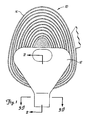
- a multi-turn inductive thin film magnetic head 10 is shown schematically in Figures 1 and 2.
- Figure 1 is a top view of the head 10 and
- Figure 2 is a side cross-sectional view.
- the head 10 includes a top pole 12 and a bottom pole 14 of a magnetic thin film core of a nickel-iron alloy. Photo-lithography is used to define the geometry of both the top pole 12 and the bottom pole 14 of the magnetic core.
- Conductive coils 16, 18 extend between the poles 12, 14 and are electrically insulated therefrom by an insulating layer 20.
- the head 10 is deposited upon a non-magnetic substrate 22 comprising a ceramic compound such as Al2O3-TiC, and an undercoat 23 of Al2O3.
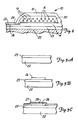
- Figures 3A to 3I show the steps of a method according to the present invention.
- Figure 3A shows, in cross section, the substrate 22 and the undercoat 23.
- the substrate 22 and the undercoat 23 are generally very large relative to the head 10 so that many replicas of the head 10 may be deposited across the entire surface of the substrate 22 and the undercoat 23.
- Figure 3B shows the substrate 22 and the undercoat 23 including a lower pole tip 26 of NiFe deposited upon the substrate 22 and the undercoat 23 using photo-lithographic techniques.
- Figure 3B shows the width of the lower pole tip 26.
- Figure 3C depicts the lower pole tip 26 and includes a layer 28 of gap material which also covers the substrate 22 and a seed layer 27 of nickel-iron.
- the seed layer 27 is deposited by sputtering and serves as a base layer for electro-deposition.
- the layer 28 of gap material typically comprises Al2O3.
- FIG 3D two photo-resist dams 29 have been deposited upon the layer 28 of gap material and the seed layer 27 whilst leaving uncovered the area where an upper pole tip 24 will be deposited.
- the photo-resist dams 29 may be deposited using standard photo-lithographic and masking techniques.
- the upper pole tip 24 of NiFe is then deposited in the area between the photo-resist dams 29 on the exposed portion of the layer 28 of gap material and the seed layer 27 as shown in Figure 3E.
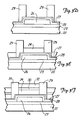
- Figure 3F shows the pole tip region following deposition of sacrificial mask layers 30, 32. Although two sacrificial mask layers are shown in Figure 3F a single sacrificial mask layer may be used.
- the sacrificial mask layer 30 comprises a copper layer deposited, for example, by electro-deposition on the upper pole tip 24.
- the sacrificial mask layer 32 is then deposited on the sacrificial mask layer 30.
- Other metals or alloys can also be used for the sacrificial masks such as Au, Zn, Cd, In, Pd, Os, Rh and Pt and alloys thereof, but copper and nickel-iron are preferred because they are compatible with thin film magnetic head manufacturing processes.
- the photo-resist dams 29 are stripped as shown in Figure 3G.
- the seed layer 27, under the area of the dams 29, is etched by sputtering or ion milling and the layer 28 of gap material, under the dam area, is chemically etched with dilute hydrofluoric acid (HF), such as 10% by volume (1:10).
- HF dilute hydrofluoric acid
- the seed layer 27 can also be etched chemically.
- the seed layer 27, the layer 28 of gap material and the lower pole tip 26 are all ion milled in a single step. The advantage of chemically etching either or both the seed layer 27 and the layer 28 of gap material is to reduce the thickness of the sacrificial mask.
- Figure 3G illustrates the process of ion milling in which ions are accelerated through a charged grid and bombard the surface of the pole tip structure as shown by the arrows.
- the high energy ions primarily impact the exposed surface of the layer 28 of gap material, the lower pole tip 26 and the sacrificial mask layer 32.
- the sacrificial mask layer 32 comprises a nickel-iron alloy wherein the milling rates thereof and the lower pole tip 26 are substantially equal.
- the milling conditions may be as follows:-
- the lower and upper pole tip thicknesses varies from 2 to 4 microns.
- the layer 28 of gap material has a thickness which varies between 0.45 and 0.65 microns. EMT 130 by EM Corporation or acetone is used to remove the photo-resist. If the thickness of the pole tips is 2.5 microns and the gap thickness of the layer of gap material is 0.6 microns, the sacrificial mask layers 30, 32 should have a thickness of 2 microns and 2.5 microns respectively.
- the sacrificial mask layer 30 of copper was selectively etched using a mixture of Metex Mu-A and Mu-B (2:1) (trade name of MacDermid Company), a copper etchant.
- the mixture can be diluted with pure water (1:10) to slow the rate of etching.
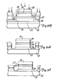
- Figure 3H shows the pole tip structure following the ion milling process in which a residual layer of the sacrificial mask layer 30 remains upon the upper pole tip 24.
- the milling process has removed the non-aligned portions of the lower pole tip 26.
- a suitable selective copper etch is Mu-A and Mu-B (2:1) produced by MacDermid Company.
- Ammonium sulphate (120 g/l) with neutral pH is another suitable copper etchant.
- Figure 3I is a cross-sectional view of Figure 1 taken along the line 3I-3I.
- the layer 28 of gap material may be etched away prior to milling using HF-H2O (1:10). This should be a short duration etch about (1 to 3 minutes) so that metals in the thin film magnetic head structure, such as nickel-iron, are not damaged. Photo-resist stripper is used to remove the photo-resist.
- the top sacrificial mask layer comprises a photo-resist, cured by heat or ultra-violet radiation to induce a negative slope.
- the sacrificial mask layers 30, 32 should be 2 microns and 5 to 6 microns, respectively.
- a bottom sacrificial mask layer e.g. the sacrificial mask layer 32
- Criteria for successive sacrificial mask layers include:-
- a metal or alloy sacrificial mask layer may be used in aligning pole tips of a thin film magnetic head. If a multi-layered mask is used, excess mask material may be removed either selectively with a chemical etchant or with a lift off process in which a lower sacrificial mask layer comprising a metal or alloy is selectively, chemically etched away. The lift off process allows the use of sacrificial layers which would normally be difficult to remove without damage to the magnetic head structure.
Abstract
Description
- This invention relates to methods of manufacturing thin film magnetic heads.
- Thin film magnetic read/write heads are used for magnetically reading and writing information upon a magnetic storage medium such as a magnetic disk or magnetic tape. It is highly desirable to provide a high density of information storage on the magnetic storage medium.
- Increased storage density in a recording system may be achieved by providing an areal density as high as possible for a given recording surface. In the case of rotating disk drives (both floppy and hard disk), the areal density is found by multiplying the number of flux reversals per unit length along the track (linear density in units of flux reversals per unit length (e.g. inch)) by the number of tracks available per unit length in the radial direction (track density in units of tracks per unit length (e.g. inch)).
- The demand for increased storage density in magnetic storage media has lead to reduced magnetic head dimensions. Magnetic heads are now fabricated in a manner similar to that used for semi-conductor integrated circuits in the electronics industry.
- During fabrication, many thin film magnetic heads are deposited across the entire surface of a wafer (or substrate). After the layers are deposited, the wafer is "diced" or sliced into many individual thin film heads, each carried by a portion of the wafer so that an upper pole tip, a lower pole tip, and a gap are exposed. The pole tips and the gap (and the portion of the substrate which underlies them) are then lapped in a direction generally inwards, toward the centre of the thin film magnetic head, to achieve the desired dimensions. This lapping process is a grinding process in which the exposed portion of the upper and lower pole tips and the gap are applied to an abrasive, such as a diamond slurry. Electrical contacts are connected to conductive coils. The completed head is next attached to a carrying fixture for use in reading and writing data on a magnetic storage medium such as a computer disk.
- In operation, a magnetic storage medium is placed near the exposed upper and lower pole tips. During a read operation, the changing magnetic flux of the moving storage medium impresses a changing magnetic flux upon upper and lower pole tips. This magnetic flux is carried through the pole tips and yoke core around the conductive coil. The changing magnetic flux induces an electrical voltage across the conductive coil which may be detected using electrical detection circuitry. The electrical voltage is representative of the changing magnetic flux produced by the moving magnetic storage medium.
- During a write operation, an electrical current is caused to flow in the conductive coil. This electric current induces a magnetic field in top and bottom magnetic poles and causes a magnetic field across the gap between the upper and lower pole tips. A fringe field extends in the vicinity beyond the boundary of the pole tips and into the nearby magnetic storage medium. This fringe field may be used to impress magnetic fields upon the magnetic storage medium and write information.
- There are two methods used to fabricate thin film magnetic heads, either additive or subtractive. The additive approach is the dominant approach and involves a series of processing steps in which the various layers of the thin film magnetic head are deposited upon a wafer substrate. The highest track density achievable is strongly influenced by the accuracy of alignment of upper and lower pole tips and their width. Magnetic pole tips typically have a pole thickness in the range of about 1 micron to about 5 microns depending upon the design criteria, i.e. a thicker pole for better over-writing efficiency and a thinner pole for increased resolution capability during the read back operation. The physical shape of upper and lower pole tips and gaps significantly affect the reading and writing performance of the thin film magnetic head by altering the shape of the magnetic fringe field.
- As track density increases, currently approaching and exceeding 945 tracks per cm (2400 tracks per inch), the alignment between the upper and lower pole tips in thin film magnetic read/write heads has become critical. At such a high storage density, design criteria require magnetic transducers in which the lower pole tip width is very nearly the same as the upper pole tip width. Upper and lower pole tips should also be in close alignment. At these small dimensions, alignment between the pole tips becomes critical, particularly as dimensions of the pole tips approach the tolerance and definition limits of the deposition techniques. A technique which provides better pole alignment begins with an upper pole, lower pole and a gap area separating the upper and lower poles, all fabricated substantially wider than desired. A narrower mask layer is then deposited upon the upper pole. The structure is then aligned using a material removal process ("milling") such as ion milling or reactive ion milling in which high energy ions bombard the pole tip region to remove the excess material (upper pole, lower pole and gap material) that extends beyond the edges of the mask layer. The mask layer protects only a portion of the upper pole, lower pole and gap so that the width of the completed pole tips is approximately the same as the width of the mask layer.
- This alignment technique suffers from a number of drawbacks. The mask layer is difficult to remove from the pole tip structure following the milling process. To ensure adequate protection of the pole tips during milling, the mask must be very thick to withstand the milling process. A thick mask, however, decreases the maximum attainable resolution. Furthermore, if the remaining mask material is stripped away following milling, the delicate structure of the thin film magnetic head may be damaged. If, on the other hand, the mask layer is made thinner to improve resolution and facilitate removal of the mask following ion milling, the risk of damaging the pole tip structure during milling is increased.
- According to one aspect of the present invention there is provided a method of manufacturing a thin film magnetic head on a substrate characterised by comprising the steps of: depositing a magnetic bottom pole layer on the substrate; depositing a gap material layer on the magnetic bottom pole layer; depositing a magnetic upper pole layer on the gap material layer; and depositing a selectively etchable platable metal sacrificial mask layer on the magnetic upper pole layer.
- According to another aspect of the present invention there is provided a method of manufacturing a thin film magnetic head upon a substrate comprising the steps of: depositing a magnetic bottom pole layer upon the substrate; depositing a gap material layer upon the magnetic bottom pole layer; depositing coil and insulator layers upon the gap layer; electro-plating through a photo-resist mask a magnetic upper pole layer upon the gap material layer; and electro-plating over the magnetic upper pole through the same photo-resist mask a first sacrificial mask layer comprising a metal.
- The present invention seeks to provide closely aligned pole tips in a thin film magnetic transducer thereby allowing increased data storage densities. In the present invention, only the bottom pole layer and the gap layer are trimmed into alignment with the upper pole layer. During ion milling or dry etching of the bottom pole layer and/or the gap layer, a top pole tip is protected by a sufficiently thick sacrificial metal mask layer which is designed to be easily applied and selectively removed after the milling process. The sacrificial mask is self aligned to the top pole by depositing it through the same photo-resist mask through which the top pole is deposited.
- In one embodiment of the present invention, a lower pole with a wider tip than is necessary in the final design is deposited upon a substrate. Next, gap material is deposited upon the lower pole. Coils and insulation are deposited over the lower pole and gap layer. The coils and insulation are confined to the yoke area and do not cover a lower pole tip and gap. Finally, an upper pole layer is deposited on the structure. The upper pole is plated through a photo-resist mask which has a pole tip width defining the track width in the final design. Prior to milling, the pole tips need not be in perfect alignment. However, the top pole is narrower than the bottom pole, and its projection must be completely enclosed by the bottom pole tip. Next, another metal layer is deposited upon the upper pole layer through the same photo-resist mask used to deposit the top pole layer. This metal layer forms the sacrificial mask for the subsequent ion milling. This metal mask may be any metal or alloy other than the material used for magnetic poles, but it must be selectively etchable, so that the magnetic pole material is not attacked. It must also be compatible for deposition upon the magnetic pole layer. In a preferred embodimnent of the present invention, this metal is copper or gold, both of which are already used in the production of thin film heads. Therefore, the geometry of the top pole (and the metal sacrificial mask layer) defines the shape of the bottom pole tip subsequent to milling. Copper is the most preferred metal for reasons of economy, ion milling rates and simplicity.
- The metal sacrificial mask layer can be used as a base layer upon which one or more additional sacrificial mask materials are deposited through the same photo-resist mask used to deposit the top pole layer and first sacrificial mask layer. In one embodiment of the present invention, a layer of nickel-iron alloy is deposited upon the metal sacrificial base layer. Nickel-iron is the material typically used for top and bottom pole layers and is therefore easy to integrate into the manufacturing process. Furthermore, because the sacrificial mask nickel-iron layer will have a milling rate equal to the milling rate of the bottom pole tip layer (since they consist of the same material), an adequate thickness of the nickel-iron sacrificial layer is readily deposited.
- After the sacrificial mask layer(s) are deposited, the photo-resist mask (through which the top pole and sacrificial mask layer(s) were deposited) is stripped off, the seed layer is removed, the gap material is wet etched or ion milled, and the pole tip structure is exposed to an ion milling process in which high energy ions bombard the surface of the pole tip. The mask protects the areas of the top and bottom pole tips and gap layer directly below the mask from the milling process. Those areas of the bottom pole tip and/or gap layer exposed to the high energy ions are milled away due to the impact force from the ions.
- Following the milling process, the top and bottom pole tips and gap layer are in alignment and the excess sacrificial mask layer remains on the upper pole tip. The wafer is next exposed to a selective chemical etch which etches away the metal or alloy sacrificial layer from the upper pole tip but does not attack the nickel-iron poles or gap material, and leaves the thin film head structure intact. In a multiple layer sacrificial mask, should any excess nickel-iron sacrificial layer remain on the first metal sacrificial layer, it is removed through "lift-off" in which the underlying metal layer (such as copper) is selectively etched away from below by the action of the chemical etch and the remains of the nickel-iron sacrificial layer falls away.
- In another embodiment of the present invention a cured photo-resist top sacrificial layer is deposited using standard photo-lithographic and masking techniques. The photo-resist layer is used in place of the sacrificial nickel-iron layer. Photoresist is presently used in the manufacture of thin film magnetic heads and a photo-resist sacrificial layer therefore is easy to implement in present day manufacturing processes. Following the processes of ion milling, the photo-resist is stripped by a photo-resist stripper and the copper layer is removed with a copper etch as described above. Any excess sacrificial mask photo-resist which remains on the copper layer is removed by "lift off".
- A multi-metal layer sacrificial mask is advantageous because a different colour second metal layer facilitates end point detection (i.e. when the milling of the nickel-iron is complete, the underlying copper coloured mask layer becomes easily visible). The thickness of the nickel-iron second sacrificial layer covering the copper sacrificial layer should be equal to, or slightly less than the thickness of the bottom pole tip. Also, because nickel-iron has a slower milling rate than copper, it helps to reduce the total thickness of the mask.
- The invention is illustrated, merely by way of example, in the accompanying drawings, in which:-
- Figure 1 shows a top view of a thin film magnetic read/write head;
- Figure 2 is a side cross-sectional view of the head of Figure 1 taken along the line 2 - 2; and
- Figures 3A to 3I illustrate steps of a method according to the present invention for manufacturing a thin film magnetic head.
- A multi-turn inductive thin film
magnetic head 10 is shown schematically in Figures 1 and 2. Figure 1 is a top view of thehead 10 and Figure 2 is a side cross-sectional view. Thehead 10 includes atop pole 12 and abottom pole 14 of a magnetic thin film core of a nickel-iron alloy. Photo-lithography is used to define the geometry of both thetop pole 12 and thebottom pole 14 of the magnetic core. Conductive coils 16, 18 extend between thepoles layer 20. Thehead 10 is deposited upon anon-magnetic substrate 22 comprising a ceramic compound such as Al₂O₃-TiC, and anundercoat 23 of Al₂O₃. - In fabricating the
head 10, several separate pattern transfer processes are used to deposit thehead 10 on thesubstrate 22 and theundercoat 23. These transfer processes include chemical etching, plating and sputtering. A typical head fabrication process may account for more than a dozen masking levels and more than thirty processing steps. - Figures 3A to 3I show the steps of a method according to the present invention.
- Figure 3A shows, in cross section, the
substrate 22 and theundercoat 23. Thesubstrate 22 and theundercoat 23 are generally very large relative to thehead 10 so that many replicas of thehead 10 may be deposited across the entire surface of thesubstrate 22 and theundercoat 23. - Figure 3B shows the
substrate 22 and theundercoat 23 including alower pole tip 26 of NiFe deposited upon thesubstrate 22 and theundercoat 23 using photo-lithographic techniques. - The view of Figure 3B shows the width of the
lower pole tip 26. - Figure 3C depicts the
lower pole tip 26 and includes alayer 28 of gap material which also covers thesubstrate 22 and aseed layer 27 of nickel-iron. Theseed layer 27 is deposited by sputtering and serves as a base layer for electro-deposition. Thelayer 28 of gap material typically comprises Al₂O₃. - In Figure 3D two photo-resist
dams 29 have been deposited upon thelayer 28 of gap material and theseed layer 27 whilst leaving uncovered the area where anupper pole tip 24 will be deposited. The photo-resistdams 29 may be deposited using standard photo-lithographic and masking techniques. Theupper pole tip 24 of NiFe is then deposited in the area between the photo-resistdams 29 on the exposed portion of thelayer 28 of gap material and theseed layer 27 as shown in Figure 3E. Figure 3F shows the pole tip region following deposition of sacrificial mask layers 30, 32. Although two sacrificial mask layers are shown in Figure 3F a single sacrificial mask layer may be used. In a preferred embodiment of the present invention, thesacrificial mask layer 30 comprises a copper layer deposited, for example, by electro-deposition on theupper pole tip 24. Thesacrificial mask layer 32 is then deposited on thesacrificial mask layer 30. Other metals or alloys can also be used for the sacrificial masks such as Au, Zn, Cd, In, Pd, Os, Rh and Pt and alloys thereof, but copper and nickel-iron are preferred because they are compatible with thin film magnetic head manufacturing processes. - Next, the photo-resist
dams 29 are stripped as shown in Figure 3G. In one embodiment, theseed layer 27, under the area of thedams 29, is etched by sputtering or ion milling and thelayer 28 of gap material, under the dam area, is chemically etched with dilute hydrofluoric acid (HF), such as 10% by volume (1:10). Alternatively, theseed layer 27 can also be etched chemically. In another embodiment, theseed layer 27, thelayer 28 of gap material and thelower pole tip 26 are all ion milled in a single step. The advantage of chemically etching either or both theseed layer 27 and thelayer 28 of gap material is to reduce the thickness of the sacrificial mask. Figure 3G illustrates the process of ion milling in which ions are accelerated through a charged grid and bombard the surface of the pole tip structure as shown by the arrows. The high energy ions primarily impact the exposed surface of thelayer 28 of gap material, thelower pole tip 26 and thesacrificial mask layer 32. - In a preferred embodiment of the present invention, the
sacrificial mask layer 32 comprises a nickel-iron alloy wherein the milling rates thereof and thelower pole tip 26 are substantially equal. The milling conditions may be as follows:-
- The lower and upper pole tip thicknesses varies from 2 to 4 microns. The
layer 28 of gap material has a thickness which varies between 0.45 and 0.65 microns. EMT 130 by EM Corporation or acetone is used to remove the photo-resist. If the thickness of the pole tips is 2.5 microns and the gap thickness of the layer of gap material is 0.6 microns, the sacrificial mask layers 30, 32 should have a thickness of 2 microns and 2.5 microns respectively. - The
sacrificial mask layer 30 of copper was selectively etched using a mixture of Metex Mu-A and Mu-B (2:1) (trade name of MacDermid Company), a copper etchant. The mixture can be diluted with pure water (1:10) to slow the rate of etching. - Figure 3H shows the pole tip structure following the ion milling process in which a residual layer of the
sacrificial mask layer 30 remains upon theupper pole tip 24. As shown in Figure 3H, the milling process has removed the non-aligned portions of thelower pole tip 26. Should residue nickel-iron remain from thesacrificial mask layer 32, it is removed using a lift-off process in which thesacrificial mask layer 30 is stripped away using a copper etch, which leaves the pole tip structure shown in Figure 3I. A suitable selective copper etch is Mu-A and Mu-B (2:1) produced by MacDermid Company. Ammonium sulphate (120 g/l) with neutral pH is another suitable copper etchant. Figure 3I is a cross-sectional view of Figure 1 taken along the line 3I-3I. - The
layer 28 of gap material may be etched away prior to milling using HF-H₂O (1:10). This should be a short duration etch about (1 to 3 minutes) so that metals in the thin film magnetic head structure, such as nickel-iron, are not damaged. Photo-resist stripper is used to remove the photo-resist. - In another embodiment of the present invention, the top sacrificial mask layer comprises a photo-resist, cured by heat or ultra-violet radiation to induce a negative slope. For example, if the pole tip thickness is 2 microns and the thickness of the layer of gap material is 0.6 microns, the sacrificial mask layers 30, 32 should be 2 microns and 5 to 6 microns, respectively.
- In selecting a bottom sacrificial mask layer, e.g. the
sacrificial mask layer 32, the following are useful criteria:- - a. The bottom sacrificial mask layer should be different (or chemically distinct) from the underlying magnetic pole layer (nickel-iron).
- b. There must be a selective chemical etchant which will not attack the underlying magnetic layer (nickel-iron).
- c. The material of the bottom sacrificial mask layer should be compatible with plating through the same photo-resist mask used to plate the top magnetic pole layer.
- d. The bath used to plate the bottom sacrificial mask layer should be compatible with the top magnetic layer (nickel-iron) so that there will not be significant or spontaneous reaction.
- e. Materials having a slow ion milling rate are desirable.
- f. A bottom sacrificial mask layer having a different colour than the underlying layer is useful to facilitate end point detection when the sacrificial mask layer is etched.
- g. Materials already available during thin film head fabrication are desirable to minimise complexity.
- Criteria for successive sacrificial mask layers include:-
- a. The successive sacrificial mask layer(s) e.g. the sacrificial mask layers 30, 32, should be different (or chemically distinct) from the underlying mask layer.
- b. The material(s) of the successive sacrificial mask layer(s) should be compatible with plating through the same photo-resist mask used to plate the bottom sacrificial mask layer.
- c. The successive sacrificial mask layer(s) should have a compatible plating bath(s) which will not react significantly and spontaneously with the underlying mask layer.
- d. Materials having a slow ion milling rate are desirable.
- e. A successive sacrificial mask layer having a different colour than the underlying mask layer is useful to facilitate end point detection.
- f. Materials already available during thin film head fabrication are desirable to minimize complexity.
- In the present invention, a metal or alloy sacrificial mask layer may be used in aligning pole tips of a thin film magnetic head. If a multi-layered mask is used, excess mask material may be removed either selectively with a chemical etchant or with a lift off process in which a lower sacrificial mask layer comprising a metal or alloy is selectively, chemically etched away. The lift off process allows the use of sacrificial layers which would normally be difficult to remove without damage to the magnetic head structure.
Claims (10)
- A method of manufacturing a thin film magnetic head on a substrate (22,23) characterised by comprising the steps of: depositing a magnetic bottom pole layer (26) on the substrate; depositing a gap material layer (28) on the magnetic bottom pole layer; depositing a magnetic upper pole layer (24) on the gap material layer; and depositing a selectively etchable platable metal sacrificial mask layer (30) on the magnetic upper pole layer (24).
- A method as claimed in claim 1 characterised by including the step of ion milling the bottom pole layer (26) following depositing the metal sacrificial mask layer (30).
- A method as claimed in claim 2 characterised by including the step of selectively chemically etching the metal sacrificial mask layer (30) following the step of ion milling the bottom pole layer (26).
- A method as claimed in any preceding claim characterised by including the step of depositing a second sacrificial mask layer (32) on the metal sacrificial mask layer (30).
- A method as claimed in claim 4 characterised by including the step of ion milling the bottom pole layer (26) following depositing the second sacrificial mask layer (32).
- A method as claimed in claim 5 characterised by including the step of selectively chemically etching the metal sacrificial mask layer (30) following the step of ion milling the bottom pole layer (26).
- A method as claimed in any preceding claim characterised in that the step of depositing the or each sacrificial mask layer comprises depositing one or more of Ni-Fe, Cu, Au, Zn, Sn, Cd, In, Pd, Os, Rh and Pt and alloys thereof.
- A method as claimed in any of claims 4 to 7 characterised in that the step of depositing the second sacrificial mask layer (32) comprises the step of depositing a nickel-iron alloy.
- A method as claimed in any of claims 4 to 8 characterised in that the step of depositing the second sacrificial mask layer (32) comprises depositing a photo-resist layer.
- A method as claimed in claim 11 characterised by including the step of curing the photo-resist layer to induce a negative slope.
Applications Claiming Priority (2)
| Application Number | Priority Date | Filing Date | Title |
|---|---|---|---|
| US07/480,558 US5141623A (en) | 1990-02-15 | 1990-02-15 | Method for aligning pole tips in a thin film head |
| US480558 | 1990-02-15 |
Publications (3)
| Publication Number | Publication Date |
|---|---|
| EP0442214A2 true EP0442214A2 (en) | 1991-08-21 |
| EP0442214A3 EP0442214A3 (en) | 1993-06-30 |
| EP0442214B1 EP0442214B1 (en) | 1999-02-03 |
Family
ID=23908427
Family Applications (1)
| Application Number | Title | Priority Date | Filing Date |
|---|---|---|---|
| EP90313691A Expired - Lifetime EP0442214B1 (en) | 1990-02-15 | 1990-12-14 | A method of manufacturing thin film magnetic heads |
Country Status (7)
| Country | Link |
|---|---|
| US (1) | US5141623A (en) |
| EP (1) | EP0442214B1 (en) |
| JP (1) | JPH07105004B2 (en) |
| KR (1) | KR100212386B1 (en) |
| DE (1) | DE69032936T2 (en) |
| HK (1) | HK1012463A1 (en) |
| SG (1) | SG47666A1 (en) |
Cited By (1)
| Publication number | Priority date | Publication date | Assignee | Title |
|---|---|---|---|---|
| US7569131B2 (en) | 2002-08-12 | 2009-08-04 | International Business Machines Corporation | Method for producing multiple magnetic layers of materials with known thickness and composition using a one-step electrodeposition process |
Families Citing this family (44)
| Publication number | Priority date | Publication date | Assignee | Title |
|---|---|---|---|---|
| US5306525A (en) * | 1990-04-25 | 1994-04-26 | Kabushiki Kaisha Komatsu Seisakusho | Method of processing rod |
| JP2901749B2 (en) * | 1990-11-19 | 1999-06-07 | 株式会社日立製作所 | Magnetoresistive head |
| JPH05159221A (en) * | 1991-12-02 | 1993-06-25 | Fujitsu Ltd | Thin-film head and production thereof |
| US5820770A (en) * | 1992-07-21 | 1998-10-13 | Seagate Technology, Inc. | Thin film magnetic head including vias formed in alumina layer and process for making the same |
| US5945007A (en) | 1992-10-20 | 1999-08-31 | Cohen; Uri | Method for etching gap-vias in a magnetic thin film head and product |
| US5621595A (en) * | 1992-10-20 | 1997-04-15 | Cohen; Uri | Pinched-gap magnetic recording thin film head |
| EP0640955B1 (en) * | 1993-08-27 | 1999-05-19 | Read-Rite Corporation | Magnetic head assembly with write pole/shield structure |
| US5666250A (en) * | 1993-11-23 | 1997-09-09 | Seagate Technology, Inc. | Thin film magnetic heads with thin nickel underlayers |
| US5452164A (en) * | 1994-02-08 | 1995-09-19 | International Business Machines Corporation | Thin film magnetic write head |
| US5640753A (en) * | 1994-03-03 | 1997-06-24 | Seagate Technology, Inc. | Method of fabricating an inverted magnetoresistive head |
| US5815909A (en) * | 1994-08-26 | 1998-10-06 | Aiwa Research And Development, Inc. | Method of making a thin film magnetic head including protected via connections through an electrically insulative substrate |
| US5665251A (en) * | 1994-11-23 | 1997-09-09 | International Business Machines Corporation | RIE image transfer process for plating |
| US5703740A (en) * | 1995-08-24 | 1997-12-30 | Velocidata, Inc. | Toroidal thin film head |
| US6195232B1 (en) | 1995-08-24 | 2001-02-27 | Torohead, Inc. | Low-noise toroidal thin film head with solenoidal coil |
| JPH09153204A (en) * | 1995-11-29 | 1997-06-10 | Read Rite S M I Kk | Production of thin film magnetic head |
| US5784772A (en) * | 1995-12-21 | 1998-07-28 | Storage Technology Corporation | Method of simultaneously forming MR sensors in a dual element MR head |
| US5811018A (en) * | 1996-01-31 | 1998-09-22 | Storage Technology Corporation | Magnetic barrier for gap control in interleaved tape head design |
| US5752309A (en) * | 1996-06-14 | 1998-05-19 | Quantum Corporation | Method and apparatus for precisely dimensioning pole tips of a magnetic transducing head structure |
| US5804085A (en) * | 1997-01-30 | 1998-09-08 | Quantum Corporation | Process for producing a pole-trimmed writer in a magnetoresistive read/write head and a data transducer made thereby |
| US5916423A (en) * | 1997-05-06 | 1999-06-29 | International Business Machines Corporation | P1 notched write head with minimum overmilled p1 and p2 |
| US5966800A (en) * | 1997-07-28 | 1999-10-19 | Read-Rite Corporation | Method of making a magnetic head with aligned pole tips and pole layers formed of high magnetic moment material |
| US6586049B2 (en) * | 1997-08-28 | 2003-07-01 | Tdk Corporation | Patterning method using mask and manufacturing method for composite type thin film magnetic head using the patterning method |
| JP3421259B2 (en) | 1997-12-25 | 2003-06-30 | ティーディーケイ株式会社 | Etching mask, manufacturing method and etching method thereof, and magnetic head and manufacturing method thereof |
| US6137660A (en) * | 1997-12-29 | 2000-10-24 | Matsushita-Kotobuki Electronics | Method for reducing ESD and imaging damage during focused ion beam definition of magnetoresistive head write track width |
| US6024884A (en) * | 1998-03-12 | 2000-02-15 | Storage Technology Corporation | Method for creating microstructures |
| US6158107A (en) * | 1998-04-02 | 2000-12-12 | International Business Machines Corporation | Inverted merged MR head with plated notched first pole tip and self-aligned second pole tip |
| US6172848B1 (en) | 1998-04-10 | 2001-01-09 | International Business Machines Corporation | Write head with self aligned pedestal shaped pole tips that are separated by a zero throat height defining layer |
| US6445536B1 (en) * | 1998-08-27 | 2002-09-03 | Read-Rite Corporation | Dielectric stencil-defined write head for MR, GMR, and spin valve high density recording heads |
| US6826011B1 (en) | 1998-11-18 | 2004-11-30 | Seagate Technology Llc | Writer design eliminating transition curvature for very narrow writer widths |
| US6228276B1 (en) * | 1999-02-05 | 2001-05-08 | Headway Technologies, Inc. | Method of manufacturing magnetoresistive (MR) sensor element with sunken lead structure |
| US6362934B1 (en) | 1999-03-24 | 2002-03-26 | Storage Technology Corporation | Highly aligned thin film tape head and method of making same |
| US6291138B1 (en) * | 1999-07-23 | 2001-09-18 | Headway Technologies, Inc. | Masking frame plating method for forming masking frame plated layer |
| US6477765B1 (en) * | 1999-11-04 | 2002-11-12 | Storage Technology Corporation | Method of fabricating a magnetic write transducer |
| JP4006164B2 (en) * | 2000-04-13 | 2007-11-14 | 株式会社日立グローバルストレージテクノロジーズ | Recording / reproducing type thin film head and method of manufacturing the head |
| JP2002208115A (en) * | 2000-11-10 | 2002-07-26 | Tdk Corp | Manufacturing method for thin film magnetic head |
| US6798622B2 (en) * | 2000-12-11 | 2004-09-28 | Headway Technologies, Inc. | Magnetoresistive (MR) sensor element with sunken lead structure |
| US6958885B1 (en) | 2000-12-21 | 2005-10-25 | Western Digital (Fremont), Inc. | Insulation layer structure for inductive write heads and method of fabrication |
| US6785953B2 (en) * | 2001-06-18 | 2004-09-07 | International Business Machines Corporation | Process of fabricating a write head with protection of a second pole tip thickness |
| US6906893B2 (en) * | 2002-10-08 | 2005-06-14 | Hitachi Global Storage Technologies | Magnetic head coil and structure for protecting same during pole notch processing |
| US7506428B2 (en) * | 2003-09-30 | 2009-03-24 | Hitachi Global Storage Technologies Netherlands B.V. | Ion mill process with sacrificial mask layer to fabricate pole tip for perpendicular recording |
| US7449348B1 (en) * | 2004-06-02 | 2008-11-11 | Advanced Micro Devices, Inc. | Feedback control of imprint mask feature profile using scatterometry and spacer etchback |
| US7818875B2 (en) * | 2005-12-07 | 2010-10-26 | Hitachi Global Storage Technologies Netherlands B.V. | Method of manufacturing a magnetic head with integration of a small flash field, zero bias, and non-reactive ion milling for pole tip uniformity |
| US8108985B2 (en) | 2007-11-02 | 2012-02-07 | Hitachi Global Storage Technologies Netherlands B.V. | Method for manufacturing a perpendicular magnetic write head |
| KR102537526B1 (en) * | 2016-05-31 | 2023-05-26 | 삼성전자 주식회사 | Semiconductor device |
Citations (5)
| Publication number | Priority date | Publication date | Assignee | Title |
|---|---|---|---|---|
| US4436593A (en) * | 1981-07-13 | 1984-03-13 | Memorex Corporation | Self-aligned pole tips |
| US4791719A (en) * | 1983-12-22 | 1988-12-20 | Hitachi, Ltd. | Method of manufacturing a thin-film magnetic head |
| JPH01128212A (en) * | 1987-11-12 | 1989-05-19 | Sumitomo Metal Ind Ltd | Manufacture of magnetic pole for thin film magnetic head |
| EP0442212A2 (en) * | 1990-02-15 | 1991-08-21 | Seagate Technology International | A method of manufacturing a thin film magnetic transducer |
| EP0442213A2 (en) * | 1990-02-15 | 1991-08-21 | Seagate Technology International | Method of manufacturing a pole tip structure in a thin film magnetic transducer |
Family Cites Families (3)
| Publication number | Priority date | Publication date | Assignee | Title |
|---|---|---|---|---|
| US4399479A (en) * | 1981-02-04 | 1983-08-16 | Eastman Kodak Company | Thin film magnetic head having good low frequency response |
| US4481071A (en) * | 1983-12-29 | 1984-11-06 | International Business Machines Corporation | Process of lift off of material |
| JPH01173308A (en) * | 1987-12-28 | 1989-07-10 | Hitachi Ltd | Manufacture of thin film magnetic head |
-
1990
- 1990-02-15 US US07/480,558 patent/US5141623A/en not_active Expired - Lifetime
- 1990-11-28 JP JP2328787A patent/JPH07105004B2/en not_active Expired - Lifetime
- 1990-11-30 KR KR1019900019604A patent/KR100212386B1/en not_active IP Right Cessation
- 1990-12-14 EP EP90313691A patent/EP0442214B1/en not_active Expired - Lifetime
- 1990-12-14 DE DE69032936T patent/DE69032936T2/en not_active Expired - Fee Related
- 1990-12-14 SG SG1996003620A patent/SG47666A1/en unknown
-
1998
- 1998-12-15 HK HK98113415A patent/HK1012463A1/en not_active IP Right Cessation
Patent Citations (5)
| Publication number | Priority date | Publication date | Assignee | Title |
|---|---|---|---|---|
| US4436593A (en) * | 1981-07-13 | 1984-03-13 | Memorex Corporation | Self-aligned pole tips |
| US4791719A (en) * | 1983-12-22 | 1988-12-20 | Hitachi, Ltd. | Method of manufacturing a thin-film magnetic head |
| JPH01128212A (en) * | 1987-11-12 | 1989-05-19 | Sumitomo Metal Ind Ltd | Manufacture of magnetic pole for thin film magnetic head |
| EP0442212A2 (en) * | 1990-02-15 | 1991-08-21 | Seagate Technology International | A method of manufacturing a thin film magnetic transducer |
| EP0442213A2 (en) * | 1990-02-15 | 1991-08-21 | Seagate Technology International | Method of manufacturing a pole tip structure in a thin film magnetic transducer |
Non-Patent Citations (4)
| Title |
|---|
| "Lagerstoffe bis Milch", Ullmann Encyclop{die der technischen Chemie, 4. Auflage, Band 16, 1978, Verlag Chemie - Weinheim - New York, p.380-381 * |
| "Nickel Teil B- Lieferung 2", Gmelins Handbuch der anorganischen Chemie, System-Nummer 57, 1996, Verlag Chemie GmbH- Weinheim/Bergstr., p.952 * |
| IBM TECHNICAL DISCLOSURE BULLETIN. vol. 24, no. 3, August 1981, ARMONK NEW YORK US page 1470 R.A. GARDNER ET AL. 'MANUFACTURE OF THIN FILM MAGNETIC HEAD' * |
| PATENT ABSTRACTS OF JAPAN vol. 13, no. 375 (P-921)(3723) 21 August 1989 & JP-A-1 128 212 ( SUMITOMO METAL IND. LTD. ) 19 May 1989 * |
Cited By (1)
| Publication number | Priority date | Publication date | Assignee | Title |
|---|---|---|---|---|
| US7569131B2 (en) | 2002-08-12 | 2009-08-04 | International Business Machines Corporation | Method for producing multiple magnetic layers of materials with known thickness and composition using a one-step electrodeposition process |
Also Published As
| Publication number | Publication date |
|---|---|
| KR910015969A (en) | 1991-09-30 |
| SG47666A1 (en) | 1998-04-17 |
| JPH03252907A (en) | 1991-11-12 |
| US5141623A (en) | 1992-08-25 |
| EP0442214A3 (en) | 1993-06-30 |
| DE69032936T2 (en) | 1999-06-10 |
| EP0442214B1 (en) | 1999-02-03 |
| HK1012463A1 (en) | 1999-07-30 |
| DE69032936D1 (en) | 1999-03-18 |
| JPH07105004B2 (en) | 1995-11-13 |
| KR100212386B1 (en) | 1999-08-02 |
Similar Documents
| Publication | Publication Date | Title |
|---|---|---|
| EP0442214B1 (en) | A method of manufacturing thin film magnetic heads | |
| US5200056A (en) | Method for aligning pole tips in a thin film head | |
| US5137750A (en) | Method of making a thin film head with contoured pole face edges for undershoot reduction | |
| US5650897A (en) | Thin film magnetic head including lightning arrester and process for making the same | |
| US5835315A (en) | Wafer including scribe line grooves for separating thin film heads and process for making the same | |
| EP0442213B1 (en) | Method of manufacturing a pole tip structure in a thin film magnetic transducer | |
| US5059278A (en) | Selective chemical removal of coil seed-layer in thin film head magnetic transducer | |
| US4992901A (en) | Self aligned magnetic poles using sacrificial mask | |
| US4639289A (en) | Process for producing a magnetic read - write head and head obtained by this process | |
| US4652954A (en) | Method for making a thin film magnetic head | |
| US6018862A (en) | Thin-film magnetic recording head using a plated metal gap layer | |
| US4436593A (en) | Self-aligned pole tips | |
| US7377024B2 (en) | Method of making a magnetic write head with trailing shield throat pad | |
| US5699605A (en) | Method for forming a magnetic thin film head with recessed basecoat | |
| EP0752699A1 (en) | Alignment of magnetic poles of thin film transducer | |
| JPH0916908A (en) | Thin-film magnetic core coil assembly | |
| EP0385023B1 (en) | A thin film magnetic read/write head and method of forming the same | |
| US5084957A (en) | Method for aligning thin film head pole tips | |
| US5048175A (en) | Method for grounding pole structures in thin film magnetic heads | |
| US6775098B2 (en) | Magnetic recording head with dielectric layer separating magnetic pole tips extensions from the zero throat coil insulator | |
| JP2552189B2 (en) | Method of manufacturing thin film magnetic head | |
| JP3336681B2 (en) | Thin film magnetoresistive head and method of manufacturing the same | |
| JPH0612624A (en) | Thin-film magnetic head |
Legal Events
| Date | Code | Title | Description |
|---|---|---|---|
| PUAI | Public reference made under article 153(3) epc to a published international application that has entered the european phase |
Free format text: ORIGINAL CODE: 0009012 |
|
| AK | Designated contracting states |
Kind code of ref document: A2 Designated state(s): DE FR GB IT NL |
|
| PUAL | Search report despatched |
Free format text: ORIGINAL CODE: 0009013 |
|
| AK | Designated contracting states |
Kind code of ref document: A3 Designated state(s): DE FR GB IT NL |
|
| RAP1 | Party data changed (applicant data changed or rights of an application transferred) |
Owner name: SEAGATE TECHNOLOGY INTERNATIONAL |
|
| 17P | Request for examination filed |
Effective date: 19931203 |
|
| 17Q | First examination report despatched |
Effective date: 19941026 |
|
| GRAG | Despatch of communication of intention to grant |
Free format text: ORIGINAL CODE: EPIDOS AGRA |
|
| GRAG | Despatch of communication of intention to grant |
Free format text: ORIGINAL CODE: EPIDOS AGRA |
|
| GRAH | Despatch of communication of intention to grant a patent |
Free format text: ORIGINAL CODE: EPIDOS IGRA |
|
| GRAH | Despatch of communication of intention to grant a patent |
Free format text: ORIGINAL CODE: EPIDOS IGRA |
|
| GRAA | (expected) grant |
Free format text: ORIGINAL CODE: 0009210 |
|
| AK | Designated contracting states |
Kind code of ref document: B1 Designated state(s): DE FR GB IT NL |
|
| PG25 | Lapsed in a contracting state [announced via postgrant information from national office to epo] |
Ref country code: IT Free format text: LAPSE BECAUSE OF FAILURE TO SUBMIT A TRANSLATION OF THE DESCRIPTION OR TO PAY THE FEE WITHIN THE PRE;WARNING: LAPSES OF ITALIAN PATENTS WITH EFFECTIVE DATE BEFORE 2007 MAY HAVE OCCURRED AT ANY TIME BEFORE 2007. THE CORRECT EFFECTIVE DATE MAY BE DIFFERENT FROM THE ONE RECORDED.SCRIBED TIME-LIMIT Effective date: 19990203 Ref country code: NL Free format text: LAPSE BECAUSE OF FAILURE TO SUBMIT A TRANSLATION OF THE DESCRIPTION OR TO PAY THE FEE WITHIN THE PRESCRIBED TIME-LIMIT Effective date: 19990203 Ref country code: FR Free format text: LAPSE BECAUSE OF FAILURE TO SUBMIT A TRANSLATION OF THE DESCRIPTION OR TO PAY THE FEE WITHIN THE PRESCRIBED TIME-LIMIT Effective date: 19990203 |
|
| REF | Corresponds to: |
Ref document number: 69032936 Country of ref document: DE Date of ref document: 19990318 |
|
| NLV1 | Nl: lapsed or annulled due to failure to fulfill the requirements of art. 29p and 29m of the patents act | ||
| EN | Fr: translation not filed | ||
| PLBE | No opposition filed within time limit |
Free format text: ORIGINAL CODE: 0009261 |
|
| STAA | Information on the status of an ep patent application or granted ep patent |
Free format text: STATUS: NO OPPOSITION FILED WITHIN TIME LIMIT |
|
| 26N | No opposition filed | ||
| REG | Reference to a national code |
Ref country code: GB Ref legal event code: 732E |
|
| PGFP | Annual fee paid to national office [announced via postgrant information from national office to epo] |
Ref country code: GB Payment date: 20011102 Year of fee payment: 12 |
|
| PGFP | Annual fee paid to national office [announced via postgrant information from national office to epo] |
Ref country code: DE Payment date: 20011205 Year of fee payment: 12 |
|
| REG | Reference to a national code |
Ref country code: GB Ref legal event code: IF02 |
|
| PG25 | Lapsed in a contracting state [announced via postgrant information from national office to epo] |
Ref country code: GB Free format text: LAPSE BECAUSE OF NON-PAYMENT OF DUE FEES Effective date: 20021214 |
|
| PG25 | Lapsed in a contracting state [announced via postgrant information from national office to epo] |
Ref country code: DE Free format text: LAPSE BECAUSE OF NON-PAYMENT OF DUE FEES Effective date: 20030701 |
|
| GBPC | Gb: european patent ceased through non-payment of renewal fee |
Effective date: 20021214 |