EP0444520A2 - Sensor arrangement - Google Patents
Sensor arrangement Download PDFInfo
- Publication number
- EP0444520A2 EP0444520A2 EP91102489A EP91102489A EP0444520A2 EP 0444520 A2 EP0444520 A2 EP 0444520A2 EP 91102489 A EP91102489 A EP 91102489A EP 91102489 A EP91102489 A EP 91102489A EP 0444520 A2 EP0444520 A2 EP 0444520A2
- Authority
- EP
- European Patent Office
- Prior art keywords
- radiation
- sensor device
- material layer
- base part
- guide body
- Prior art date
- Legal status (The legal status is an assumption and is not a legal conclusion. Google has not performed a legal analysis and makes no representation as to the accuracy of the status listed.)
- Withdrawn
Links
Images

Classifications
-
- G—PHYSICS
- G01—MEASURING; TESTING
- G01N—INVESTIGATING OR ANALYSING MATERIALS BY DETERMINING THEIR CHEMICAL OR PHYSICAL PROPERTIES
- G01N21/00—Investigating or analysing materials by the use of optical means, i.e. using sub-millimetre waves, infrared, visible or ultraviolet light
- G01N21/17—Systems in which incident light is modified in accordance with the properties of the material investigated
- G01N21/41—Refractivity; Phase-affecting properties, e.g. optical path length
- G01N21/43—Refractivity; Phase-affecting properties, e.g. optical path length by measuring critical angle
-
- B—PERFORMING OPERATIONS; TRANSPORTING
- B60—VEHICLES IN GENERAL
- B60S—SERVICING, CLEANING, REPAIRING, SUPPORTING, LIFTING, OR MANOEUVRING OF VEHICLES, NOT OTHERWISE PROVIDED FOR
- B60S1/00—Cleaning of vehicles
- B60S1/02—Cleaning windscreens, windows or optical devices
- B60S1/04—Wipers or the like, e.g. scrapers
- B60S1/06—Wipers or the like, e.g. scrapers characterised by the drive
- B60S1/08—Wipers or the like, e.g. scrapers characterised by the drive electrically driven
- B60S1/0818—Wipers or the like, e.g. scrapers characterised by the drive electrically driven including control systems responsive to external conditions, e.g. by detection of moisture, dirt or the like
- B60S1/0822—Wipers or the like, e.g. scrapers characterised by the drive electrically driven including control systems responsive to external conditions, e.g. by detection of moisture, dirt or the like characterized by the arrangement or type of detection means
- B60S1/0833—Optical rain sensor
-
- B—PERFORMING OPERATIONS; TRANSPORTING
- B60—VEHICLES IN GENERAL
- B60S—SERVICING, CLEANING, REPAIRING, SUPPORTING, LIFTING, OR MANOEUVRING OF VEHICLES, NOT OTHERWISE PROVIDED FOR
- B60S1/00—Cleaning of vehicles
- B60S1/02—Cleaning windscreens, windows or optical devices
- B60S1/04—Wipers or the like, e.g. scrapers
- B60S1/06—Wipers or the like, e.g. scrapers characterised by the drive
- B60S1/08—Wipers or the like, e.g. scrapers characterised by the drive electrically driven
- B60S1/0818—Wipers or the like, e.g. scrapers characterised by the drive electrically driven including control systems responsive to external conditions, e.g. by detection of moisture, dirt or the like
- B60S1/0822—Wipers or the like, e.g. scrapers characterised by the drive electrically driven including control systems responsive to external conditions, e.g. by detection of moisture, dirt or the like characterized by the arrangement or type of detection means
- B60S1/0874—Wipers or the like, e.g. scrapers characterised by the drive electrically driven including control systems responsive to external conditions, e.g. by detection of moisture, dirt or the like characterized by the arrangement or type of detection means characterized by the position of the sensor on the windshield
- B60S1/0881—Wipers or the like, e.g. scrapers characterised by the drive electrically driven including control systems responsive to external conditions, e.g. by detection of moisture, dirt or the like characterized by the arrangement or type of detection means characterized by the position of the sensor on the windshield characterized by the attachment means on the windshield
Definitions
- the present invention is based on a sensor device designed according to the preamble of the main claim and intended for detecting the degree of wetting of a glass pane with drop-shaped precipitation.
- Devices of this type are provided in particular for quantitatively detecting the amount of moisture which is deposited on the front or rear window of a motor vehicle per unit of time and automatically influencing a window wiper system assigned to the glass window as a function thereof.
- DE 33 14 770 C1 discloses a device for controlling a windshield wiper motor, in which a radiation guide body is coupled to a window by means of optical cement and in which a radiation transmitter and a radiation receiver are assigned to the radiation guide body via radiation lenses.
- the radiation transmitter and the radiation receiver are arranged in such a way that the radiation beam emerging from the radiation exit element of the radiation transmitter is opposite the beam into the radiation entry element the radiation receiver incoming radiation beam is offset by approximately 90 o, in the associated area of the light conducting the Strahlenein- or exit barriers.
- a reflection means is provided in the area lying between the two ray lenses, which is formed from an area portion of the surface of the glass pane facing the radiation guide body and from an air space assigned to it.
- the present invention is therefore based on the object of developing a sensor device of the type mentioned at the outset in such a way that optimum functionality is ensured even with relatively large temperature differences by the correct assignment of a reflection means which is relatively simple to produce and can be arranged without great effort.
- a heating device which acts in particular on the radiation guide body. This ensures that the entire sensor device is brought to a certain temperature level, for example 40.degree. C., within a relatively short time, as a result of which on the one hand a reduction in temperature errors and on the other hand partial heating of the glass pane is achieved.
- a precipitate that is present as snowflakes on the glass pane is thawed and can thus be detected.
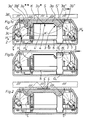
- a sensor device provided for detecting the degree of wetting of a pane S preferably made of glass, with in particular drop-shaped precipitation, essentially consists of a radiation guide body 3 assigned on the one hand to a radiation transmitter 1 and on the other hand to a radiation receiver 2, which is not attached by means of an optical cement K surface S 'of disc S exposed to precipitation is attached.
- the pane S is, in particular, the windshield of a motor vehicle, on which the sensor device arranged in a housing G is present at an exposed point, that is to say one which does not impair the view, but which is predestined for detecting the precipitation.
- the radiation guide body 3 consists of a base part 3a, which is basically trapezoidal, on the two of which are located opposite trapezoidal surfaces 3a ', 3a''each have a radiation lens 3b', 3b ''.
- the two trapezoidal surfaces 3a ', 3a''of the same size are arranged on the base part 3a such that the center lines of the two beam lenses 3b', 3b '' are offset from each other by an angle ⁇ of 90 ° .
- the radiation lenses can either be attached to the trapezoidal surfaces 3a ', 3a'', for example with the aid of a centering pin and optical cement, or they can be formed in one piece directly on the base part 3a.
- a very thin material layer 4 (shown oversized in the drawing) is attached to allow multiple reflection of the rays emitted by the radiation transmitter 1, said layer of material 4 being between the two radiation lenses 3b ', 3b''located area of the base part 3a is present and extends parallel to the disc S.
- the Radiation guide 3 can be made much smaller or can be used with a thicker pane (as shown in FIG. 2).
- a heating device which acts in particular on the radiation guide body and is not shown for the sake of simplicity, for example consisting of a PTC resistor.
- the holding means are each composed of a U-shaped holding spring H1 and the free ends, designed as clip elements, assigned to the same and provided in the base body with recesses 3e.
- truncated cone-like projections 3c are also formed on the base body 3a, on one end of which hollow-cylindrical holding elements H2 are press-fitted.
- a circuit board 5 provided for the connection and possibly the fixing of the radiation transmitter 1 and the radiation receiver 2 is fastened, for example, by means of press-in pins H2 '.
- the radiation guide body 3 is provided all around with a profiled extension 3d which engages with a correspondingly profiled region of the upper housing part G2. On the one hand, this prevents to a certain extent that air can penetrate into the sensor device and pollutants in the air (tobacco smoke, plastic evaporation, etc.) can be deposited on the radiation lenses, for example. On the other hand, the entry of extraneous radiation from this direction is also avoided.
- an appropriately designed and arranged seal could be used instead of the aforementioned means.
- FIGS. 1c and 1d several (two) radiation guide bodies 3 are combined to form a one-piece block unit for the purpose of enlarging the measuring field and provided with a common material layer 4.
- the optical separation between the individual radiation guide bodies 3, each of which cooperates with a radiation transmitter 1 and a radiation receiver 2, is ensured by a partition wall T which engages in a recess 3f of the base body 3a and is present on the upper housing part G2.
- partition walls T1 in the housing which are provided as over-radiation protection for rays not entering the radiation body.
- the sensor device preferably works on the basis of either visible light rays or infrared rays, the radiation transmitter being designed as a light-emitting diode and the radiation receiver being designed as a photodiode.
Abstract
Description
Die vorliegende Erfindung geht von einer gemäß dem Oberbegriff des Hauptanspruches konzipierten, zur Erfassung des Benetzungsgrades einer Glasscheibe mit tropfenförmigem Niederschlag vorgesehenen Sensoreinrichtung aus.The present invention is based on a sensor device designed according to the preamble of the main claim and intended for detecting the degree of wetting of a glass pane with drop-shaped precipitation.
Derartige Einrichtungen sind insbesondere dafür vorgesehen, um die auf der Front- oder der Heckscheibe eines Kraftfahrzeuges sich pro Zeiteinheit niederschlagende Feuchtigkeit mengenmäßig in repräsentativer Form zu erfassen und in Abhängigkeit davon ein der Glasscheibe zugeordnetes Scheibenwischsystem automatisch zu beeinflussen.Devices of this type are provided in particular for quantitatively detecting the amount of moisture which is deposited on the front or rear window of a motor vehicle per unit of time and automatically influencing a window wiper system assigned to the glass window as a function thereof.
Durch die DE 33 14 770 C1 ist eine Einrichtung zum Steuern eines Scheibenwischermotors bekanntgeworden, bei der ein Strahlenleitkörper mittels optischen Kitt an eine Scheibe angekoppelt wird und bei der dem Strahlenleitkörper über Strahlenlinsen ein Strahlensender und ein Strahlenempfänger zugeordnet sind. Der Strahlensender und der Strahlenempfänger sind dabei so angeordnet, daß das aus dem Strahlenaustrittselement des Strahlensenders austretende Strahlenbündel gegenüber dem in das Strahleneintrittselement des Strahlenempfängers eintretende Strahlenbündel um etwa 90o versetzt ist, und zwar in dem dem Strahlenleitkörper zugeordneten Bereich des Strahlenein- bzw. -austritts. Zur Erzielung einer Mehrfachreflexion der Strahlen ist in dem zwischen den beiden Strahlenlinsen liegenden Bereich ein Reflexionsmittel vorgesehen, das aus einem Flächenanteil der dem Strahlenleitkörper zugewandten Oberfläche der Glasscheibe und aus einem demselben zugeordneten Luftraum gebildet ist. Bei einer solchen Ausführungsform besteht jedoch das Problem, daß infolge der an einer dem Niederschlag ausgesetzten Glasscheibe zwangsläufig auftretenden Temperaturunterschiede sich auf dem für die Reflexion der Strahlen vorgesehenen Flächenanteil der Glasscheibe Kondensat aus dem zugeordneten Luftraum abschlägt, wodurch die Reflexionseigenschaften verändert werden. Aufgrund dessen erfährt die vom Strahlenempfänger detektierte Strahlenintensität eine Verfälschung, wodurch sich auch das von dem Strahlenempfänger gelieferte Signal verändert und damit das nachgeschaltete Aggregat - wie z.B. das Scheibenwischsystem eines Kraftfahrzeuges in einer nicht korrekten Weise beeinflußt.DE 33 14 770 C1 discloses a device for controlling a windshield wiper motor, in which a radiation guide body is coupled to a window by means of optical cement and in which a radiation transmitter and a radiation receiver are assigned to the radiation guide body via radiation lenses. The radiation transmitter and the radiation receiver are arranged in such a way that the radiation beam emerging from the radiation exit element of the radiation transmitter is opposite the beam into the radiation entry element the radiation receiver incoming radiation beam is offset by approximately 90 o, in the associated area of the light conducting the Strahlenein- or exit barriers. In order to achieve multiple reflection of the rays, a reflection means is provided in the area lying between the two ray lenses, which is formed from an area portion of the surface of the glass pane facing the radiation guide body and from an air space assigned to it. In such an embodiment, however, there is the problem that, due to the temperature differences inevitably occurring on a glass pane exposed to the precipitation, condensate from the associated air space is reflected on the surface portion of the glass pane provided for the reflection of the rays, as a result of which the reflection properties are changed. As a result, the radiation intensity detected by the radiation receiver is falsified, as a result of which the signal supplied by the radiation receiver also changes and thus influences the downstream unit, such as the windshield wiper system of a motor vehicle, in an incorrect manner.
Darüberhinaus ist durch die DE 38 23 300 C1 eine Sensoreinrichtung bekanntgeworden, bei der das für eine Mehrfachreflexion vorgesehene Reflexionsmittel aus einem sich parallel zur Glasscheibe erstreckenden, in das Basisteil des Strahlenleitkörpers eingebrachten Reflexionsblech besteht. Bei einem derartigen Aufbau einer Sensoreinrichtung kann es infolge von recht beachtlichen, bei einem Kraftfahrzeug in der Größenordnung von ca. 130 K (-40oC bis +90oC) liegenden Temperaturunterschieden zu Mikrorissen des Strahlenleitkörpers kommen, und zwar aufgrund der unterschiedlichen Ausdehnungskoeffizienten des aus Glas, Plexiglas oder dergleichen hergestellten Strahlenleitkörpers und des relativ dick auszuführenden, insbesondere aus Aluminium bestehenden Reflexionsbleches. Solche Mikrorisse können den Strahlenverlauf wesentlich beeinflussen und bis zum vollkommenen Funktionsausfall der Sensoreinrichtung führen. Um diesem Effekt entgegenzuwirken, müßte das Reflexionsblech wesentlich dünner gestaltet werden. Einem derartigen Vorgehen sind aber Grenzen gesetzt und zwar dadurch, daß das Reflexionsblech in dem für die Formgebung des Strahlenleitkörpers vorgesehenen Werkzeug definiert gehalten werden muß und sich beim Einbringen des den Strahlenleitkörper bildenden Materials nicht verwerfen darf.In addition, a sensor device has become known from DE 38 23 300 C1, in which the reflection means provided for multiple reflection consists of a reflection plate which extends parallel to the glass pane and is introduced into the base part of the radiation guide body. With such a construction of a sensor device, micro-cracks in the radiation guide body can occur due to the considerable temperature differences in the order of approximately 130 K (-40 o C to +90 o C), due to the different expansion coefficients of the made of glass, plexiglass or the like radiation guide body and the relatively thick to be made, in particular made of aluminum reflecting sheet. Such microcracks can have a significant influence on the beam path and to the full Cause the sensor device to fail. In order to counteract this effect, the reflective sheet would have to be made much thinner. There are limits to such an approach, however, in that the reflection plate must be held in a defined manner in the tool provided for shaping the radiation guide body and must not be warped when the material forming the radiation guide body is introduced.
Der vorliegenden Erfindung liegt deshalb die Aufgabe zugrunde, eine Sensoreinrichtung der eingangs erwähnten Art derart weiterzubilden, daß eine optimale Funktionsfähigkeit auch bei relativ großen Temperaturunterschieden durch einwandfreie Zuordnung eines relativ einfach herzustellenden und ohne großen Aufwand anzuordnenden Reflexionsmittels gewährleistet ist.The present invention is therefore based on the object of developing a sensor device of the type mentioned at the outset in such a way that optimum functionality is ensured even with relatively large temperature differences by the correct assignment of a reflection means which is relatively simple to produce and can be arranged without great effort.
Erfindungsgemäß wird die Aufgabe durch die im kennzeichnenden Teil des Hauptanspruches angegebenen Merkmale gelöst. Vorteilhaft bei einer derartigen Ausgestaltung einer Sensoreinrichtung ist, daß durch die Anbringung einer sehr dünnen und damit Temperaturunterschiede auffangenden, eine Totalreflexion gewährleistenden Materialschicht es zu keiner Beeinflussung des Meßergebnisses durch Feuchtigkeit kommen kann.According to the invention the object is achieved by the features specified in the characterizing part of the main claim. An advantage of such a configuration of a sensor device is that the application of a very thin material layer, which thus absorbs temperature differences and ensures total reflection, does not influence the measurement result due to moisture.
Im Zusammenhang mit einer so ausgebildeten Sensoreinrichtung ist es günstig, wenn derselben eine insbesondere auf den Strahlenleitkörper einwirkende Heizvorrichtung zugeordnet wird. Hierdurch wird erreicht, daß die gesamte Sensoreinrichtung innerhalb einer relativ kurzen Zeit auf ein bestimmtes Temperaturniveau, z.B. 40oC, gebracht wird, wodurch einerseits eine Reduktion von Temperaturfehlern und andererseits eine partielle Erwärmung der Glasscheibe erreicht wird. Durch die Aufheizung der Glasscheibe wird ein als Schneeflocken auf der Glasscheibe vorhandener Niederschlag aufgetaut, der damit detektiert werden kann.In connection with a sensor device designed in this way, it is expedient if it is assigned a heating device which acts in particular on the radiation guide body. This ensures that the entire sensor device is brought to a certain temperature level, for example 40.degree. C., within a relatively short time, as a result of which on the one hand a reduction in temperature errors and on the other hand partial heating of the glass pane is achieved. By heating the glass pane, a precipitate that is present as snowflakes on the glass pane is thawed and can thus be detected.
Weitere vorteilhafte Ausgestaltungen des erfindungsgemäßen Gegenstandes sind in den Unteransprüchen angegeben und werden anhand eines in der Zeichnung dargestellten Ausführungsbeispieles einer entsprechend aufgebauten Sensoreinrichtung näher erläutert. Dabei zeigen
- Fig. 1a
- eine Sensoreinrichtung im Schnitt gemäß Linie A-A der Figur 1d
- Fig. 1b
- die Sensoreinrichtung im Schnitt gemäß Linie B-B der Figur 1d
- Fig. 1c
- eine als Blockeinheit aufgebaute Sensoreinrichtung im Schnitt gemäß Linie C-C der Figur 1a
- Fig. 1d
- die als Blockeinheit aufgebaute Sensoreinrichtung nach Figur 1c in Draufsicht
- Fig. 2
- eine weitere Sensoreinrichtung in entsprechend Linie A-A der Figur 1d geschnittener Ansicht.
- Fig. 1a
- a sensor device in section along line AA of Figure 1d
- Fig. 1b
- the sensor device in section along line BB of Figure 1d
- Fig. 1c
- a sensor device constructed as a block unit in section along line CC of Figure 1a
- Fig. 1d
- the sensor device constructed as a block unit according to Figure 1c in plan view
- Fig. 2
- a further sensor device in a sectional view corresponding to line AA of Figure 1d.
Wie aus der Zeichnung hervorgeht, besteht eine zur Erfassung des Benetzungsgrades einer vorzugsweise aus Glas bestehenden Scheibe S mit insbesondere tropfenförmigem Niederschlag vorgesehene Sensoreinrichtung im wesentlichen aus einem einerseits einem Strahlensender 1 und andererseits einem Strahlenempfänger 2 zugeordneten Strahlenleitkörper 3, der mittels optischen Kitt K auf der nicht dem Niederschlag ausgesetzten Oberfläche S' der Scheibe S befestigt wird. Bei der Scheibe S handelt es sich insbesondere um die Windschutzscheibe eines Kraftfahrzeuges, an der die in einem Gehäuse G angeordnete Sensoreinrichtung an exponierter, d.h. die Sicht nicht beeinträchtigender, jedoch für die Erfassung des Niederschlags prädestinierter Stelle vorhanden ist. Der Strahlenleitkörper 3 besteht dabei aus einem prinzipiell trapezförmig ausgebildeten Basisteil 3a, an dessen beiden sich gegenüberliegenden Trapezflächen 3a',3a'' jeweils eine Strahlenlinse 3b',3b'' vorhanden ist. Die beiden gleich groß ausgeführten Trapezflächen 3a',3a'' sind hierbei so am Basisteil 3a angeordnet, daß die Mittellinien der beiden Strahlenlinsen 3b',3b'' um einen Winkel α von 90o gegeneinander versetzt sind. Die Strahlenlinsen können dabei entweder an den Trapezflächen 3a',3a'' z.B. unter Zuhilfenahme von jeweils einem Zentrierstift und optischem Kitt befestigt oder direkt am Basisteil 3a einstückig ausgeformt sein.As can be seen from the drawing, a sensor device provided for detecting the degree of wetting of a pane S, preferably made of glass, with in particular drop-shaped precipitation, essentially consists of a
An der von der Scheibe S abgewandten Oberfläche 3a* des Basisteils 3a ist zur Ermöglichung einer Mehrfachreflexion der vom Strahlensender 1 emittierten Strahlen eine sehr dünne Materialschicht 4 (in der Zeichnung überdimensional dargestellt) angebracht, die in dem zwischen den beiden Strahlenlinsen 3b',3b'' befindlichen Bereich des Basisteils 3a vorhanden ist und sich parallel zu der Scheibe S erstreckt. Diese zur Ermöglichung von einwandfreien Reflexionen der Strahlen eine vorzugsweise aus Reinstaluminium gebildete, der Scheibe S zugewandte hochglänzende Oberfläche 4' aufweisende Materialschicht 4 steht mit ihrer Oberfläche 4' in dem genannten Bereich vollständig mit dem Strahlenleitkörper 3 in Verbindung, wodurch vermieden ist, daß zwischen der Materialschicht 4 und dem Strahlenleitkörper 3 Luft eindringen und damit Kondensat auf der Oberfläche 3a* bzw. der zugeordneten Oberfläche 4' bilden kann.
Die entweder als Metallfolie oder als metallkaschierte Kunststoffolie ausgebildete bzw. in Dünnschichttechnologie direkt auf das Basisteil 3a aufgebrachte Materialschicht 4 kann natürlich - wie in Fig. 2 dargestellt - auch auf der der Scheibe S zugewandten Oberfläche 3a** des Basisteils 3a angebracht werden, wobei dann die hochglänzende Oberfläche 4' der Materialschicht 4 über den optischen Kitt K (in der Zeichnung ebenfalls überdimensional dargestellt) der Scheibe S zugeordnet ist.
In diesem Fall kann dann aufgrund der kürzeren Strahlenwege der Strahlenleitkörper 3 wesentlich kleiner ausgeführt oder ein Einsatz bei einer dickeren Scheibe (wie in Figur 2 dargestellt) vorgenommen werden.
Im Zusammenhang mit einer so ausgebildeten Sensoreinrichtung ist es sehr vorteilhaft, wenn derselben eine insbesondere auf den Strahlenleitkörper einwirkende, der Einfachheit halber nicht dargestellte, z.B. aus einem PTC-Widerstand bestehende Heizvorrichtung zugeordnet wird.
Das an der Scheibe S durch den optischen Kitt K befestigte Basisteil 3a des Strahlenleitkörpers 3 steht über Haltemittel mit dem aus einem Gehäuseunterteil G1 und einem Gehäuseoberteil G2 bestehenden, vorzugsweise aus Kunststoff hergestellten Gehäuse G in Verbindung. Die Haltemittel setzen sich dabei jeweils aus einer U-förmig ausgebildeten Haltefeder H1 und den freien, als Clipselemente ausgebildeten Enden derselben zugeordneten, im Basiskörper vorhandenen Rastausnehmungen 3e zusammen.
An den Basiskörper 3a sind weiterhin in dem von der Scheibe S abgewandten Bereich kegelstumpfartige Ansätze 3c angeformt, auf denen hohlzylindrische Halteelemente H2 mit ihrem einen Ende unter Preßpassung befestigt sind. An dem anderen Ende dieser Halteelemente H2 ist eine für den Anschluß und gegebenenfalls die Fixierung des Strahlensenders 1 und des Strahlenempfängers 2 vorgesehene Leiterplatte 5 z.B. über Einpreßstifte H2' befestigt.
Darüberhinaus ist der Strahlenleitkörper 3 umlaufend mit einem profilierten Fortsatz 3d versehen, der mit einem entsprechend profilierten Bereich des Gehäuseoberteils G2 in Eingriff steht. Damit wird einerseits in gewissem Maße verhindert, daß Luft in die Sensoreinrichtung eindringen kann und damit sich in der Luft befindliche Schadstoffe (Tabakqualm, Kunststoffausdünstung usw.) auf z.B. den Strahlenlinsen ablagern können. Andererseits ist dadurch auch der Eintritt von Fremdstrahlungen aus dieser Richtung vermieden. Natürlich könnte anstelle der vorgenannten Mittel auch eine entsprechend ausgebildete und angeordnete Dichtung zum Einsatz gelangen.
Wie insbesondere aus den Fig. 1c und 1d hervorgeht, sind mehrere (zwei) Strahlenleitkörper 3 zwecks Vergrößerung des Meßfeldes zu einer einstückigen Blockeinheit zusammengefaßt und mit einer gemeinsamen Materialschicht 4 versehen. Die optische Trennung zwischen den einzelnen, mit jeweils einem Strahlensender 1 und einen Strahlenempfänger 2 kooperierenden Strahlenleitkörpern 3 wird durch eine in eine Ausnehmung 3f des Basiskörpers 3a eingreifende, am Gehäuseoberteil G2 vorhandene Trennwand T sichergestellt.
Darüberhinaus sind im Gehäuse weitere Trennwände T1 vorhanden, die als Überstrahlschutz für nicht in den Strahlenkörper eintretende Strahlen vorgesehen sind.On the
The
In this case the
In connection with a sensor device designed in this way, it is very advantageous if it is assigned a heating device which acts in particular on the radiation guide body and is not shown for the sake of simplicity, for example consisting of a PTC resistor.
The
In the area facing away from the pane S, truncated cone-like projections 3c are also formed on the
In addition, the
As can be seen in particular from FIGS. 1c and 1d, several (two)
In addition, there are further partition walls T1 in the housing, which are provided as over-radiation protection for rays not entering the radiation body.
Die Sensoreinrichtung arbeitet vorzugsweise auf der Basis von entweder sichtbaren Lichtstrahlen oder Infrarotstrahlen, wobei der Strahlensender als Leuchtdiode und der Strahlenempfänger als Fotodiode ausgebildet sind.The sensor device preferably works on the basis of either visible light rays or infrared rays, the radiation transmitter being designed as a light-emitting diode and the radiation receiver being designed as a photodiode.
Claims (7)
Applications Claiming Priority (2)
| Application Number | Priority Date | Filing Date | Title |
|---|---|---|---|
| DE4006174 | 1990-02-28 | ||
| DE19904006174 DE4006174C1 (en) | 1990-02-28 | 1990-02-28 |
Publications (2)
| Publication Number | Publication Date |
|---|---|
| EP0444520A2 true EP0444520A2 (en) | 1991-09-04 |
| EP0444520A3 EP0444520A3 (en) | 1992-03-18 |
Family
ID=6401071
Family Applications (1)
| Application Number | Title | Priority Date | Filing Date |
|---|---|---|---|
| EP19910102489 Withdrawn EP0444520A3 (en) | 1990-02-28 | 1991-02-21 | Sensor arrangement |
Country Status (3)
| Country | Link |
|---|---|
| EP (1) | EP0444520A3 (en) |
| BR (1) | BR9002197A (en) |
| DE (1) | DE4006174C1 (en) |
Cited By (10)
| Publication number | Priority date | Publication date | Assignee | Title |
|---|---|---|---|---|
| WO1992018848A1 (en) * | 1991-04-23 | 1992-10-29 | Introlab Pty. Limited | A moisture sensor |
| EP0562275A1 (en) * | 1992-03-25 | 1993-09-29 | Robert Bosch Gmbh | Rain sensor |
| DE4329609C1 (en) * | 1993-09-02 | 1995-02-02 | Kostal Leopold Gmbh & Co Kg | Optoelectronic sensor device |
| FR2772479A1 (en) * | 1997-12-12 | 1999-06-18 | Valeo Climatisation | Detector for sensing condensation or rain on surfaces of vehicle windscreen |
| WO1999052752A1 (en) * | 1998-04-08 | 1999-10-21 | Robert Bosch Gmbh | Sensor device for detecting moisture on a window |
| WO2001071321A1 (en) * | 2000-03-21 | 2001-09-27 | Bioquell Uk Limited | An instrument to measure the amount of condensation during a gaseous sterilisation process |
| EP1346889A3 (en) * | 2002-03-20 | 2004-01-14 | Robert Bosch Gmbh | Rain sensor, in particular for windscreens |
| EP2206601A1 (en) * | 2009-01-08 | 2010-07-14 | Saint Gobain Glass France | Plate with a function element |
| WO2010139313A1 (en) * | 2009-06-02 | 2010-12-09 | Osram Opto Semiconductors Gmbh | Measuring device, measuring system and method for measuring the contamination of a translucent measurement object |
| DE102013000751A1 (en) * | 2013-01-17 | 2014-07-17 | Hella Kgaa Hueck & Co. | Sensor device for detecting moisture on a pane |
Families Citing this family (18)
| Publication number | Priority date | Publication date | Assignee | Title |
|---|---|---|---|---|
| DE4142146C2 (en) * | 1991-12-20 | 1994-05-19 | Kostal Leopold Gmbh & Co Kg | Sensor device |
| DE4318114C2 (en) * | 1993-06-01 | 1998-07-16 | Kostal Leopold Gmbh & Co Kg | Sensor device |
| DE4329608C1 (en) * | 1993-09-02 | 1995-01-19 | Kostal Leopold Gmbh & Co Kg | Optoelectronic sensor device |
| DE4340681C2 (en) * | 1993-11-30 | 1997-09-04 | Telefunken Microelectron | Sensor system for recording the optical conditions at an interface |
| FR2722291B1 (en) * | 1994-07-06 | 1996-10-04 | Valeo Electronique | DEVICE FOR DETECTING A SURFACE CONDITION OF A VEHICLE GLASS, AND PARTICULARLY FOR DETECTING THE PRESENCE OF DROPS OF WATER ON A WINDSHIELD |
| DE4424454C2 (en) * | 1994-07-12 | 1999-08-12 | Kostal Leopold Gmbh & Co Kg | Optoelectronic sensor device for detecting the degree of wetting of a transparent motor vehicle window with precipitation |
| DE19716975B4 (en) * | 1997-04-23 | 2006-08-24 | Robert Bosch Gmbh | sensor device |
| DE19725287A1 (en) * | 1997-06-14 | 1998-12-17 | Itt Mfg Enterprises Inc | Rain sensor with bonded sensor chips |
| JPH11326185A (en) * | 1998-05-12 | 1999-11-26 | Nippon Sheet Glass Co Ltd | Liquid drop detection apparatus |
| DE19837050A1 (en) * | 1998-08-17 | 2000-02-24 | Gardena Kress & Kastner Gmbh | Liquid detection device |
| DE19955423A1 (en) | 1999-11-18 | 2001-05-31 | Hella Kg Hueck & Co | Sensor device and method for producing a sensor device |
| DE19956089A1 (en) * | 1999-11-22 | 2001-06-21 | Bayerische Motoren Werke Ag | Sensor arrangement |
| DE10147182C1 (en) * | 2001-09-25 | 2003-04-24 | Hella Kg Hueck & Co | Rain sensor for motor vehicle windscreen wiper control, has holder for transmitter and receiver in form of housing in which they are arranged with variable distance between them |
| DE10326853A1 (en) * | 2003-06-14 | 2004-12-30 | Hella Kgaa Hueck & Co. | Sensor device e.g. for measuring the fluid on disk, e.g. motor vehicle rain sensor, has housing with longitudinal axis which is perpendicularly aligned to disk |
| EP3425999A1 (en) | 2012-03-05 | 2019-01-09 | Saint-Gobain Glass France | Disc assembly with electrically heated light scattering aperture |
| DE102013009126A1 (en) | 2013-05-30 | 2014-12-04 | Hella Kgaa Hueck & Co. | sensor device |
| DE102014004451A1 (en) | 2014-03-27 | 2015-10-01 | Hella Kgaa Hueck & Co. | Method and sensor unit for detecting a degree of wetting of a pane |
| DE102015008298A1 (en) | 2015-06-29 | 2016-12-29 | Hella Kgaa Hueck & Co. | Sensor device for detecting moisture on a pane and motor vehicle |
Citations (3)
| Publication number | Priority date | Publication date | Assignee | Title |
|---|---|---|---|---|
| JPS5944641A (en) * | 1982-09-08 | 1984-03-13 | Nippon Denso Co Ltd | Liquid detector for automatic control device of wind shield wiper |
| JPS5985944A (en) * | 1982-11-08 | 1984-05-18 | Nippon Denso Co Ltd | Liquid detector for automatic wind shield wiper controller device |
| DE3823300C1 (en) * | 1988-07-09 | 1989-08-17 | Leopold Kostal Gmbh & Co Kg, 5880 Luedenscheid, De | Sensor device |
Family Cites Families (1)
| Publication number | Priority date | Publication date | Assignee | Title |
|---|---|---|---|---|
| DE3532199A1 (en) * | 1985-09-10 | 1987-03-12 | Lorenz Dr Twisselmann | Sensor for controlling the visual clarity of panes of glass |
-
1990
- 1990-02-28 DE DE19904006174 patent/DE4006174C1/de not_active Expired - Lifetime
- 1990-05-08 BR BR9002197A patent/BR9002197A/en not_active IP Right Cessation
-
1991
- 1991-02-21 EP EP19910102489 patent/EP0444520A3/en not_active Withdrawn
Patent Citations (3)
| Publication number | Priority date | Publication date | Assignee | Title |
|---|---|---|---|---|
| JPS5944641A (en) * | 1982-09-08 | 1984-03-13 | Nippon Denso Co Ltd | Liquid detector for automatic control device of wind shield wiper |
| JPS5985944A (en) * | 1982-11-08 | 1984-05-18 | Nippon Denso Co Ltd | Liquid detector for automatic wind shield wiper controller device |
| DE3823300C1 (en) * | 1988-07-09 | 1989-08-17 | Leopold Kostal Gmbh & Co Kg, 5880 Luedenscheid, De | Sensor device |
Non-Patent Citations (2)
| Title |
|---|
| PATENT ABSTRACTS OF JAPAN vol. 8, no. 147 (P-285)(1584) 10. Juli 1984 & JP-A-59 044 641 ( NIPPON DENSO ) 13. März 1984 * |
| PATENT ABSTRACTS OF JAPAN vol. 8, no. 202 (P-300)(1639) 14. September 1984 & JP-A-59 085 944 ( NIPPON DENSO ) 18. Mai 1984 * |
Cited By (14)
| Publication number | Priority date | Publication date | Assignee | Title |
|---|---|---|---|---|
| US5414257A (en) * | 1991-04-23 | 1995-05-09 | Introlab Pty Limited | Moisture sensor for detecting moisture on a windshield |
| WO1992018848A1 (en) * | 1991-04-23 | 1992-10-29 | Introlab Pty. Limited | A moisture sensor |
| EP0562275A1 (en) * | 1992-03-25 | 1993-09-29 | Robert Bosch Gmbh | Rain sensor |
| DE4329609C1 (en) * | 1993-09-02 | 1995-02-02 | Kostal Leopold Gmbh & Co Kg | Optoelectronic sensor device |
| FR2772479A1 (en) * | 1997-12-12 | 1999-06-18 | Valeo Climatisation | Detector for sensing condensation or rain on surfaces of vehicle windscreen |
| US6433501B2 (en) | 1998-04-08 | 2002-08-13 | Robert Bosch Gmbh | Sensor device for detecting moisture on a window |
| WO1999052752A1 (en) * | 1998-04-08 | 1999-10-21 | Robert Bosch Gmbh | Sensor device for detecting moisture on a window |
| WO2001071321A1 (en) * | 2000-03-21 | 2001-09-27 | Bioquell Uk Limited | An instrument to measure the amount of condensation during a gaseous sterilisation process |
| EP1346889A3 (en) * | 2002-03-20 | 2004-01-14 | Robert Bosch Gmbh | Rain sensor, in particular for windscreens |
| EP2206601A1 (en) * | 2009-01-08 | 2010-07-14 | Saint Gobain Glass France | Plate with a function element |
| WO2010139313A1 (en) * | 2009-06-02 | 2010-12-09 | Osram Opto Semiconductors Gmbh | Measuring device, measuring system and method for measuring the contamination of a translucent measurement object |
| DE102013000751A1 (en) * | 2013-01-17 | 2014-07-17 | Hella Kgaa Hueck & Co. | Sensor device for detecting moisture on a pane |
| US9709493B2 (en) | 2013-01-17 | 2017-07-18 | Hella Kgaa Hueck & Co. | Sensor device for detecting moisture on a pane |
| DE102013000751B4 (en) | 2013-01-17 | 2024-02-29 | HELLA GmbH & Co. KGaA | Sensor device for detecting moisture on a pane |
Also Published As
| Publication number | Publication date |
|---|---|
| EP0444520A3 (en) | 1992-03-18 |
| DE4006174C1 (en) | 1991-07-25 |
| BR9002197A (en) | 1991-08-13 |
Similar Documents
| Publication | Publication Date | Title |
|---|---|---|
| EP0444520A2 (en) | Sensor arrangement | |
| DE4318114C2 (en) | Sensor device | |
| DE4027367C1 (en) | Deposit detector for outer surface of pane - uses radiation source and receiver at right angles to pane esp. windscreen to detect rain drops | |
| DE69834347T2 (en) | COMPACT HUMIDITY SENSOR WITH EFFECTIVELY VERY CROPPED OPTICS | |
| EP0461424B1 (en) | Device to optically detect a coating | |
| DE4202121C1 (en) | Sensor assembly detecting wetness of motor vehicle windscreen - includes receiver for radiation reflected from precipitation esp. drops of rain | |
| DE4142146C2 (en) | Sensor device | |
| EP0679130B1 (en) | Sensor for determining the degree of wetting and/or soiling of a pane of glass, in particular the windscreen of a motor vehicle | |
| DE3823300C1 (en) | Sensor device | |
| EP0958493B1 (en) | Optical transmitting and receiving device | |
| WO2001005626A1 (en) | Light-sensitive sensor unit, especially for automatic switching of lighting devices | |
| EP1784324A1 (en) | Optoelectronic sensor device for a motor vehicle | |
| DE10331074A1 (en) | Sensor arrangement for distance and / or speed measurement | |
| WO2003101795A1 (en) | Optoelectronic sensor device | |
| DE19539422C2 (en) | Device for optically checking the translucency of the translucent pane on headlights of motor vehicles | |
| DE4427606A1 (en) | Indicator lamp for rear of car | |
| DE3806881C2 (en) | ||
| DE4329608C1 (en) | Optoelectronic sensor device | |
| DE4006420C2 (en) | Device for optically detecting foreign bodies or a coating on the surface of an optically transparent pane | |
| DE19512864C1 (en) | Car glass for a rain sensor | |
| DE19821335C2 (en) | Optoelectronic sensor device | |
| DE4343474A1 (en) | Sensor device for detecting the degree of wetting and / or contamination of windows, in particular front windows of motor vehicles | |
| DE4300741C2 (en) | Sensor device | |
| DE19545604C3 (en) | Windshield wiper system for rear windows with a moisture sensor integrated in the brake light | |
| DE4330710C1 (en) | Optoelectronic sensor device |
Legal Events
| Date | Code | Title | Description |
|---|---|---|---|
| PUAI | Public reference made under article 153(3) epc to a published international application that has entered the european phase |
Free format text: ORIGINAL CODE: 0009012 |
|
| AK | Designated contracting states |
Kind code of ref document: A2 Designated state(s): ES FR GB IT SE |
|
| PUAL | Search report despatched |
Free format text: ORIGINAL CODE: 0009013 |
|
| AK | Designated contracting states |
Kind code of ref document: A3 Designated state(s): ES FR GB IT SE |
|
| STAA | Information on the status of an ep patent application or granted ep patent |
Free format text: STATUS: THE APPLICATION IS DEEMED TO BE WITHDRAWN |
|
| 18D | Application deemed to be withdrawn |
Effective date: 19920919 |