EP0444618A2 - Plasma treatment device - Google Patents
Plasma treatment device Download PDFInfo
- Publication number
- EP0444618A2 EP0444618A2 EP91102830A EP91102830A EP0444618A2 EP 0444618 A2 EP0444618 A2 EP 0444618A2 EP 91102830 A EP91102830 A EP 91102830A EP 91102830 A EP91102830 A EP 91102830A EP 0444618 A2 EP0444618 A2 EP 0444618A2
- Authority
- EP
- European Patent Office
- Prior art keywords
- treatment device
- plasma treatment
- vacuum chamber
- workpieces
- chamber
- Prior art date
- Legal status (The legal status is an assumption and is not a legal conclusion. Google has not performed a legal analysis and makes no representation as to the accuracy of the status listed.)
- Granted
Links
Images

Classifications
-
- C—CHEMISTRY; METALLURGY
- C23—COATING METALLIC MATERIAL; COATING MATERIAL WITH METALLIC MATERIAL; CHEMICAL SURFACE TREATMENT; DIFFUSION TREATMENT OF METALLIC MATERIAL; COATING BY VACUUM EVAPORATION, BY SPUTTERING, BY ION IMPLANTATION OR BY CHEMICAL VAPOUR DEPOSITION, IN GENERAL; INHIBITING CORROSION OF METALLIC MATERIAL OR INCRUSTATION IN GENERAL
- C23C—COATING METALLIC MATERIAL; COATING MATERIAL WITH METALLIC MATERIAL; SURFACE TREATMENT OF METALLIC MATERIAL BY DIFFUSION INTO THE SURFACE, BY CHEMICAL CONVERSION OR SUBSTITUTION; COATING BY VACUUM EVAPORATION, BY SPUTTERING, BY ION IMPLANTATION OR BY CHEMICAL VAPOUR DEPOSITION, IN GENERAL
- C23C16/00—Chemical coating by decomposition of gaseous compounds, without leaving reaction products of surface material in the coating, i.e. chemical vapour deposition [CVD] processes
- C23C16/44—Chemical coating by decomposition of gaseous compounds, without leaving reaction products of surface material in the coating, i.e. chemical vapour deposition [CVD] processes characterised by the method of coating
- C23C16/54—Apparatus specially adapted for continuous coating
Definitions
- the invention relates to a plasma treatment device of the type specified in the preamble of claim 1.
- a glow discharge is generated in a vacuum between the workpiece and a counterelectrode, with certain gases being present for the plasma generation at very low pressure.
- Gas atoms interact with the surface of the workpiece at high temperatures in order to change the surface properties in the desired manner.
- methods for plasma carburizing, plasma nitriding or plasma coating of metals are known.
- the workpieces to be treated are cold placed in an oven, cleaned by a treatment at low pressure, heated under increasing pressure, then subjected to the plasma treatment and finally cooled.
- a plasma treatment device as described in DE 33 22 341 A1, has a vacuum container into which the workpiece is inserted.
- the workpiece is placed on an electrode and the inner jacket of the vacuum container or the container itself is used as a counter electrode.
- Continuous continuous operation is not possible with this known device, just like with other vacuum containers for the glow discharge treatment of workpieces. Rather, the workpieces have to be introduced into the treatment room in batches, treated and then removed again. It is not possible to process several workpieces in such a way that they are subjected to different treatment times or types of treatment. After completion of a treatment, the vacuum must be released to change the workpiece, whereby the gas and heat present in the vacuum chamber also escape.
- a treatment device with the features specified in the preamble of patent claim 1 is known from US 4,501,766.
- This device has a treatment chamber in which a rotating device is arranged in the manner of a carousel.
- the rotating device in turn carries several rotatable workpiece carriers on which the workpieces are placed.
- a gear ensures that the individual workpiece carriers are rotated on the rotating device when the rotating device rotates will.
- the treatment device is a high-frequency energy film deposition device in which the workpieces are heated and connected to an electrical potential, while a channel through which the workpieces move is connected to a counter electrode.
- Such high-frequency treatment devices operate at a relatively low temperature, so that the operation of the rotating device and the rotation of the workpiece carriers with respect to the rotating device within the chamber are readily possible.
- plasma diffusion processes require high temperatures in the order of 500 to 2000 ° C.
- the plasma treatment is usually carried out by pulsed direct current discharge in a vacuum chamber.
- plasma diffusion processes do not allow the use of components that come into frictional contact due to the temperature and vacuum conditions. Such components would be welded together or destroyed.
- the invention has for its object to provide a plasma treatment device in which different treatments, in particular different treatment times and temperatures of workpieces can be carried out in the same treatment chamber and which can be used for treatments that require relatively high temperatures.
- a rotating device here called a turntable
- a turntable is arranged in the vacuum chamber, which is preferably mounted outside the vacuum chamber. All parts of the turntable located within the vacuum chamber, that is to say in the area of high temperatures, can be rigid, so that there is no risk of malfunction due to material removal or welding. If the turntable is stored inside the vacuum chamber, the bearing is cooled.
- the turntable is a kind of storage on or on which several workpieces can be arranged.
- Adjacent to the vacuum chamber is a lock, which enables the introduction and / or removal of workpieces. Each workpiece location of the turntable can be brought to the transfer position to the lock and then, with the lock door open, the workpiece can be transferred to the lock.
- the device according to the invention is particularly suitable for plasma diffusion treatment of workpieces in which pulsed direct current discharges take place.
- plasma diffusion treatments require high temperatures of over 500 ° C under vacuum conditions. Due to the fact that the rotating device is mounted outside the vacuum chamber and the vacuum seal that seals the shaft passage or with cooling of the bearing inside the vacuum chamber, the bearing of the rotating device is not subject to the extreme load influences prevailing in the vacuum chamber.
- the turntable is preferably designed as a disc or support grid so that the workpieces can be placed on it. But it is also possible to use the turntable as a grid, star or spider or as a hanging device form, ie as a frame on which the workpieces are attached hanging.
- the same pressure and possibly gas conditions are set in the lock as in the vacuum chamber. In this way, the treatment in the vacuum chamber can be continued even during and after opening the lock door without the glow discharges being extinguished.
- the workpieces are moved in the vacuum chamber by the turntable.
- the workpieces are moved between the lock and the turntable by means of suitable handling devices which are expediently provided on the lock and which are only briefly exposed to the conditions of the vacuum chamber.
- the invention basically makes it possible to produce essentially the same processing conditions at all points in the vacuum chamber.
- the workpieces can be introduced into the vacuum chamber one after the other and removed from the vacuum chamber after the respectively anticipated treatment time. It is also possible to carry out individual workpiece processing by individually selecting the temperature and / or duration and / or the electrical voltage and / or the shape of the voltage of the glow discharge. This enables different conditions to be created at different processing positions within the vacuum chamber.
- the turntable is expediently divided into several rooms by partition walls. Each of these rooms can now be brought to a designated processing position of the vacuum chamber, where the workpiece contained in it is individually processed in accordance with the specified conditions.
- the treatment device is not limited to the two-dimensional storage of the parts on a turntable. Rather, it is also possible to use a plurality of rotary tables arranged vertically one above the other, into which the workpieces are placed via one or more Locks can be inserted. An axial movement of the turntable can also take place for charging.
- the entire process is carried out at constant pressure.
- the different treatment steps such as cleaning, pretreatment, hardening, coating, post-treatment, are achieved by varying the other process parameters, such as tension, form of tension, temperature and atmosphere.
- heat can be taken from heat stores, for example walls, when heating up. That was previously stored there by cooling parts.
- At least one of these locks can also be used as a treatment chamber in which cleaning, heating or cooling processes are carried out.
- These chambers are equipped with appropriate handling devices for moving the workpieces.
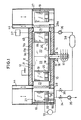
- the plasma treatment device has a vacuum chamber 10 which is enclosed by a double jacket 11.
- the double jacket 11 consists of an outer jacket 11a, an inner jacket 11b and the heat-insulating layer 11c located between them.
- the inner jacket 11b also forms the counter electrode 12, which is connected to ground potential.
- the vacuum chamber 10 is cylindrical and contains the turntable 13 with the axis of rotation running coaxially to the chamber of the vacuum axis.
- the turntable 13 is attached to the upper end of the shaft 14, which passes through a vacuum seal 15 in the bottom of the vacuum chamber and is mounted in a bearing 16 outside the vacuum chamber.
- Slip rings 17 are arranged on the shaft 14, which are connected via individual lines 18 to the various workpiece locations on the turntable 13 and which can be electrically connected to the workpieces 19.
- Each workpiece 19 stands on electrical insulators 20 on the turntable 13.
- the turntable is divided into several sector-shaped rooms 22 by partitions 21.
- the partitions extend to the vicinity of the top wall of the vacuum chamber 22 and in the radial direction to the vicinity of the side wall.
- the workpieces 19 are arranged near the edge of the turntable.
- Heating devices 45 are arranged under the ceiling of the vacuum chamber 10 at the individual processing positions under which the workpiece positions can be stopped. These heaters can be made from heating wires exist, which are part of the counter electrode 12. Each of the heating devices 45 is connected to at least one electrical line which is led out through the vacuum chamber 10 and can be connected to a separate heating current source. The heating devices 45 can thus be controlled separately, so that the temperatures in the individual rooms 22 can be set and regulated separately when the turntable 13 is at a standstill.
- a temperature sensor for example a termocouple, is assigned to each of the rooms 22 in order to regulate the temperature in this room. The measuring line of the temperature sensor is led out through the hollow shaft 14.
- the insulating layer 11c is arranged in the interior of the double jacket 11.
- This insulating layer can have different insulation values at the individual processing stations, so that different temperatures arise even with uniform heating of all processing positions at these processing positions. It is also possible to make the heat insulation adjustable at the processing positions.
- Openings 23, 24 are provided on the circumferential wall of the vacuum chamber 10 at two opposite points, through which the respective workpiece 19 can be moved. Adjacent to these openings is a lock 25, 26, which has a vacuum-tight chamber 27. Between the chamber 27 and the vacuum chamber 10 there is a door 28 which can be moved vertically and closes in a vacuum-tight manner.
- Each of the chambers 27 is approximately the size of a workpiece location on the turntable 13 and serves to receive a workpiece 19 which enters or leaves the vacuum chamber 10 to be implemented.
- the lock 25 also has two further vertically movable doors 29 and 30, which close the chamber 27 from the environment.
- a table 31 at the same height as the turntable 13.
- This table 31 serves to hold a workpiece 19 standing on insulators 20.
- This workpiece can be connected to an electrode 18a which is connected to an external voltage source 33.
- the inner wall of the chamber 27 is designed as a counter electrode and is connected to the other pole of the voltage source 33. In this way, the workpiece 19 can be pretreated by glow discharge in the chamber 27 before this workpiece is transferred into the vacuum chamber 10.
- the chamber 27 of the lock 25 is also connected via a valve 34 to an external suction pump 35 in order to be able to evacuate the chamber 27.
- the vacuum chamber 10 is connected to an external suction pump 36 for evacuating this vacuum chamber. Furthermore, the vacuum chamber 10 is connected to a gas source 37 from which the treatment gas, for example hydrogen, nitrogen, methane or argon or a gas mixture, is passed into the vacuum chamber. This treatment gas is drawn off by the suction pump 36 in order to maintain the vacuum.
- the pressure outlet of the vacuum pump 36 is connected to a collecting container 38, the outlet of which is connected via a valve 39 to the chamber 27 of the lock 25.
- the extracted treatment gas is collected under pressure in the collecting container 38.
- This treatment gas can be introduced through the throttling valve 39 into the lock 25, so that the same for the treatment in the lock Gas is used, as in the vacuum chamber 10.
- the gas pressure in both chambers 10 and 29 can be controlled so that it is between 0 and 10 mbar.
- the lock 27 also has a vacuum-tight door 28a connected to the opening 24 of the vacuum chamber and two side doors 29a, 30, each of which can be moved vertically.
- the door 29a leads to a treatment chamber 40 which has a further door 41 leading to the outside and in which the workpiece 19 is exposed to an air flow, for example to deter it.
- the door 30a leads to a treatment chamber 42 which is connected to the surroundings by a further door 43 and in which the workpiece 19 e.g. is subjected to a water treatment by sprinkling for hardening.
- the described plasma treatment device works as follows: With the door 28 closed, the workpiece to be treated is introduced through the opened door 30 into the lock 25 and connected to the electrode 18a. Then the door 30 is closed. The chamber 27 is evacuated and a treatment gas is introduced into this chamber at very low pressure. By switching on the voltage source 33, a glow discharge is caused between the workpiece 19 and the counter electrode 34. In this way, the workpiece 19 can be subjected to a surface-cleaning pretreatment in a vacuum.
- the existing atmosphere is sucked off by the pump 35 via the valve 34 and enough gas is introduced from the collecting container 38 via the valve 39 until there is pressure equilibrium between the lock 29 and the vacuum chamber 10.
- the door 28 is then opened and the workpiece 19 is moved from the chamber 29 to the turntable 13 in the vacuum chamber 10 by a manipulator (not shown). Then the door 28 is closed again and the turntable is rotated under the control of a computer so that the workpiece 19 is brought into a predetermined treatment position inside the vacuum chamber 10, where it is exposed to the action of a heater 45 and at the same time a glow discharge takes place.
- the workpiece is connected to the electrode 18. Afterwards, other processing operations can be carried out under different operating parameters in the interior of the vacuum chamber at different processing positions.
- the workpiece can either be removed from the same lock 25 through which it entered the vacuum chamber, or through the further lock 26. The workpiece can be transported from the further lock 26 into one of the treatment chambers 40 or 42.
- the same treatment of the workpieces arranged on different workpiece positions of the rotary plate 13 is possible, which are brought to the various processing stations of the vacuum chamber according to a predetermined program.
- the radiation-shielding partitions 21 largely prevent the various treatment conditions from influencing one another.
- the treatment inside the vacuum chamber 10 can be continued without the risk of the glow discharges being extinguished or being transformed into arc discharges. This is because the same gas pressure and temperature conditions can be set in the lock 25 as in the vacuum chamber 10.
- the thermal separation of the workpiece locations inside the vacuum chamber enables individual types of treatment of the individual workpieces.
- the device allows continuous operation with different treatment times for the individual workpieces.
- a process control controls the treatment and the whereabouts of the workpieces in the vacuum chamber and in the individual locks.
Abstract
Description
Die Erfindung betrifft eine Plasma-Behandlungsvorrichtung der im Oberbegriff des Patentanspruchs 1 angegebenen Art.The invention relates to a plasma treatment device of the type specified in the preamble of claim 1.
Bei der Plasmabehandlung von Werkstücken wird zwischen dem Werkstück und einer Gegenelektrode eine Glimmentladung im Vakuum erzeugt, wobei bestimmte Gase für die Plasmaerzeugung bei sehr geringem Druck anwesend sind. Dabei wechselwirken Gasatome unter hohen Temperaturen mit der Oberfläche des Werkstücks, um die Oberflächenbeschaffenheit in gewünschter Weise zu verändern. Bekannt sind beispielsweise Verfahren zum Plasma-Aufkohlen, Plasmanitrieren oder Plasmabeschichten von Metallen. Die zu behandelnden Werkstücke werden kalt in einen Ofen eingebracht, durch eine Behandlung bei niedrigem Druck gereinigt, unter zunehmenden Druck aufgeheizt, dann der Plasmabehandlung unterzogen und schließlich abgekühlt.In the plasma treatment of workpieces, a glow discharge is generated in a vacuum between the workpiece and a counterelectrode, with certain gases being present for the plasma generation at very low pressure. Gas atoms interact with the surface of the workpiece at high temperatures in order to change the surface properties in the desired manner. For example, methods for plasma carburizing, plasma nitriding or plasma coating of metals are known. The workpieces to be treated are cold placed in an oven, cleaned by a treatment at low pressure, heated under increasing pressure, then subjected to the plasma treatment and finally cooled.
Eine Plasma-Behandlungsvorrichtung, wie sie in DE 33 22 341 A1 beschrieben ist, weist einen Vakuumbehälter auf, in den das Werkstück eingebracht wird. Das Werkstück wird an eine Elektrode gelegt und der Innenmantel des Vakuumbehälters oder der Behälter selbst wird als Gegenelektrode benutzt. Bei dieser bekannten Vorrichtung, ebenso wie bei anderen Vakuumbehältern für die Glimmentladungsbehandlung von Werkstücken, ist ein kontinuierlicher Durchlaufbetrieb nicht möglich. Die Werkstücke müssen vielmehr chargenweise in den Behandlungsraum eingebracht, behandelt und danach wieder entfernt werden. Es ist nicht möglich, mehrere Werkstücke in der Weise zu bearbeiten, daß sie unterschiedlichen Behandlungsdauern oder Behandlungsarten unterworfen werden. Nach Beendigung einer Behandlung muß zum Werkstückwechsel das Vakuum aufgehoben werden, wobei auch das in der Vakuumkammer vorhandene Gas und die Wärme entweichen. Daß ein kontinuierlicher Betrieb der Vakuumkammer für die Glimmentladungsbehandlung nicht möglich ist, liegt daran, daß die hohen auftretenden Temperaturen in der Größenordnung von 500 bis 2000 °C den Einsatz von Fördereinrichtungen nicht erlauben. Bei den in der Vakuumkammer herrschenden Temperaturen und Entladungsverhältnissen neigen Bauteile, die miteinander in Berührung kommen, zum Verschweißen und zu Erosion. Daher sind bei den bekannten Plasmawärmebehandlungsvorrichtungen sämtliche Teile während der Behandlung feststehend.A plasma treatment device, as described in
Eine Behandlungsvorrichtung mit den im Oberbegriff des Patentanspruchs 1 angegebenen Merkmalen ist bekannt aus US 4 501 766. Diese Vorrichtung weist eine Behandlungskammer auf, in der eine Dreheinrichtung nach Art eines Karussells angeordnet ist. Die Dreheinrichtung trägt ihrerseits mehrere drehbare Werkstückträger, auf die die Werkstücke aufgesetzt werden. Ein Getriebe sorgt dafür, daß bei Rotation der Drehvorrichtung die einzelnen Werkstückträger auf der Dreheinrichtung gedreht werden. Die Behandlungsvorrichtung ist eine mit Hochfrequenzenergie arbeitende Filmablagerungsvorrichtung, bei der die Werkstücke beheizt und an ein elektrisches Potential angeschlossen sind, während ein Kanal, durch den sich die Werkstücke bewegen, mit einer Gegenelektrode verbunden ist. Solche Hochfrequenz-Behandlungseinrichtungen arbeiten mit relativ geringer Temperatur, so daß der Betrieb der Dreheinrichtung und die Drehung der Werkstückträger in Bezug auf die Dreheinrichtung innerhalb der Kammer ohne weiteres möglich sind.A treatment device with the features specified in the preamble of patent claim 1 is known from US 4,501,766. This device has a treatment chamber in which a rotating device is arranged in the manner of a carousel. The rotating device in turn carries several rotatable workpiece carriers on which the workpieces are placed. A gear ensures that the individual workpiece carriers are rotated on the rotating device when the rotating device rotates will. The treatment device is a high-frequency energy film deposition device in which the workpieces are heated and connected to an electrical potential, while a channel through which the workpieces move is connected to a counter electrode. Such high-frequency treatment devices operate at a relatively low temperature, so that the operation of the rotating device and the rotation of the workpiece carriers with respect to the rotating device within the chamber are readily possible.
Im Gegensatz zu Behandlungen, die bei relativ niedrigen Betriebstemperaturen stattfinden, erfordern Plasma-Diffusionsverfahren hohe Temperaturen in der Größenordnung von 500 bis 2000 °C. Dabei erfolgt in der Regel die Plasmabehandlung durch gepulste Gleichstromentladung in einer Vakuumkammer. Im Gegensatz zu Beschichtungsverfahren erlauben Plasma-Diffusionsverfahren wegen der Temperatur- und Vakuumbedingungen nicht den Einsatz von Bauteilen, die in reibende Berührung miteinander kommen. Solche Bauteile würden miteinander verschweißt oder zerstört werden.In contrast to treatments that take place at relatively low operating temperatures, plasma diffusion processes require high temperatures in the order of 500 to 2000 ° C. The plasma treatment is usually carried out by pulsed direct current discharge in a vacuum chamber. In contrast to coating processes, plasma diffusion processes do not allow the use of components that come into frictional contact due to the temperature and vacuum conditions. Such components would be welded together or destroyed.
Der Erfindung liegt die Aufgabe zugrunde, eine Plasma-Behandlungsvorrichtung zu schaffen, bei der in derselben Behandlungskammer unterschiedliche Behandlungen, insbesondere unterschiedliche Behandlungsdauern und Temperaturen von Werkstücken durchgeführt werden können und die für Behandlungen, welche relativ hohe Temperaturen erfordern, verwendet werden kann.The invention has for its object to provide a plasma treatment device in which different treatments, in particular different treatment times and temperatures of workpieces can be carried out in the same treatment chamber and which can be used for treatments that require relatively high temperatures.
Die Lösung dieser Aufgabe erfolgt erfindungsgemäß mit den im Patentanspruch 1 angegebenen Merkmalen.This object is achieved according to the invention with the features specified in claim 1.
Bei der erfindungsgemäßen Plasma-Behandlungsvorrichtung ist in der Vakuumkammer eine Dreheinrichtung, hier Drehteller genannt, angeordnet, die vorzugsweise außerhalb der Vakuumkammer gelagert ist. Sämtliche innerhalb der Vakuumkammer, also im Bereich hoher Temperaturen, befindlichen Teile des Drehtellers können starr sein, so daß nicht die Gefahr der Funktionsstörung durch Materialabtrag oder Verschweißen besteht. Wenn der Drehteller im Inneren der Vakuumkammer gelagert ist, wird das Lager gekühlt. Der Drehteller ist gewissermaßen ein Speicher auf oder an dem mehrere Werkstücke angeordnet werden können. Angrenzend an die Vakuumkammer ist eine Schleuse angeordnet, die das Einbringen und/oder Ausbringen von Werkstücken ermöglicht. Jeder Werkstückplatz des Drehtellers kann in die Übergabeposition zur Schleuse gebracht werden und dann, bei geöffneter Schleusentür, kann das Werkstück in die Schleuse überführt werden. Die erfindungsgemäße Vorrichtung eignet sich besonders für Plasma-Diffusionsbehandlung von Werkstücken, bei denen gepulste Gleichstromentladungen erfolgen. Solche Plasma-Diffusionsbehandlungen erfordern hohe Temperaturen von über 500 °C unter Vakuumbedingungen. Dadurch, daß die Dreheinrichtung außerhalb der Vakuumkammer und der den Wellendurchgang abdichtenden Vakuumdichtung oder unter Kühlung des Lagers im Innern der Vakuumkammer gelagert ist, unterliegt das Lager der Dreheinrichtung nicht den in der Vakuumkammer herrschenden extremen Belastungseinflüssen.In the plasma treatment device according to the invention, a rotating device, here called a turntable, is arranged in the vacuum chamber, which is preferably mounted outside the vacuum chamber. All parts of the turntable located within the vacuum chamber, that is to say in the area of high temperatures, can be rigid, so that there is no risk of malfunction due to material removal or welding. If the turntable is stored inside the vacuum chamber, the bearing is cooled. The turntable is a kind of storage on or on which several workpieces can be arranged. Adjacent to the vacuum chamber is a lock, which enables the introduction and / or removal of workpieces. Each workpiece location of the turntable can be brought to the transfer position to the lock and then, with the lock door open, the workpiece can be transferred to the lock. The device according to the invention is particularly suitable for plasma diffusion treatment of workpieces in which pulsed direct current discharges take place. Such plasma diffusion treatments require high temperatures of over 500 ° C under vacuum conditions. Due to the fact that the rotating device is mounted outside the vacuum chamber and the vacuum seal that seals the shaft passage or with cooling of the bearing inside the vacuum chamber, the bearing of the rotating device is not subject to the extreme load influences prevailing in the vacuum chamber.
Der Drehteller ist vorzugsweise als Scheibe oder Traggitter ausgebildet, um die Werkstücke daraufstellen zu können. Es ist aber auch möglich, den Drehteller als Gitter, Stern oder Spinne oder als Aufhängevorrichtung auszubilden, d.h. als ein Gestell, an dem die Werkstücke hängend befestigt werden.The turntable is preferably designed as a disc or support grid so that the workpieces can be placed on it. But it is also possible to use the turntable as a grid, star or spider or as a hanging device form, ie as a frame on which the workpieces are attached hanging.
Bevor die Schleusentür zwischen Schleuse und Vakuumkammer geöffnet wird, werden in der Schleuse die gleichen Druck- und eventuell auch Gasbedingungen eingestellt wie in der Vakuumkammer. Auf diese Weise kann die Behandlung in der Vakuumkammer auch während und nach dem Öffnen der Schleusentür fortgesetzt werden, ohne daß die Glimmentladungen erlöschen.Before the lock door between the lock and the vacuum chamber is opened, the same pressure and possibly gas conditions are set in the lock as in the vacuum chamber. In this way, the treatment in the vacuum chamber can be continued even during and after opening the lock door without the glow discharges being extinguished.
Natürlich können außer einzelnen Werkstücken auch ganze Werkstückchargen bearbeitet werden. Das Bewegen der Werkstücke in der Vakuumkammer erfolgt durch den Drehteller. Das Bewegen der Werkstücke zwischen Schleuse und Drehteller erfolgt durch geeignete Handlingvorrichtungen, die zweckmäßigerweise an der Schleuse vorgesehen sind und die nur kurzzeitig den Bedingungen der Vakuumkammer ausgesetzt werden.Of course, apart from individual workpieces, entire workpiece batches can also be processed. The workpieces are moved in the vacuum chamber by the turntable. The workpieces are moved between the lock and the turntable by means of suitable handling devices which are expediently provided on the lock and which are only briefly exposed to the conditions of the vacuum chamber.
Die Erfindung ermöglicht es grundsätzlich, in der Vakuumkammer an allen Stellen im wesentlichen gleiche Bearbeitungsbedingungen herzustellen. Dabei können die Werkstücke nacheinander in die Vakuumkammer eingebracht und nach der jeweils vorgesehnen Behandlungsdauer wieder aus der Vakuumkammer entfernt werden. Es besteht auch die Möglichkeit individuelle Werkstückbearbeitungen vorzunehmen, indem die Temperatur und/oder Dauer und/oder die elektrische Spannung und/oder die Form der Spannung der Glimmentladung individuell gewählt wird. Dies ermöglicht, daß an unterschiedlichen Bearbeitungspositionen innerhalb der Vakuumkammer unterschiedliche Bedingungen geschaffen werden. Um die Bearbeitungspositionen voneinander zu trennen, ist zweckmäßigerweise der Drehteller durch Trennwände in mehrere Räume unterteilt. Jeder dieser Räume kann nun an eine vorgesehene Bearbeitungsposition der Vakuumkammer gebracht werden, wo das in ihm enthaltene Werkstück entsprechend den vorgegebenen Bedingungen individuell bearbeitet wird.The invention basically makes it possible to produce essentially the same processing conditions at all points in the vacuum chamber. The workpieces can be introduced into the vacuum chamber one after the other and removed from the vacuum chamber after the respectively anticipated treatment time. It is also possible to carry out individual workpiece processing by individually selecting the temperature and / or duration and / or the electrical voltage and / or the shape of the voltage of the glow discharge. This enables different conditions to be created at different processing positions within the vacuum chamber. In order to separate the processing positions from one another, the turntable is expediently divided into several rooms by partition walls. Each of these rooms can now be brought to a designated processing position of the vacuum chamber, where the workpiece contained in it is individually processed in accordance with the specified conditions.
Die Behandlungs-Vorrichtung ist nicht auf die zweidimmensionale Speicherung der Teile auf einem Drehteller beschränkt. Vielmehr können auch mehrere vertikal übereinander angeordnete Drehteller verwendet werden, in die die Werkstücke über eine oder mehrere Schleusen eingelegt werden können. Dabei kann zum Chargieren auch eine axiale Bewegung der Drehteller erfolgen.The treatment device is not limited to the two-dimensional storage of the parts on a turntable. Rather, it is also possible to use a plurality of rotary tables arranged vertically one above the other, into which the workpieces are placed via one or more Locks can be inserted. An axial movement of the turntable can also take place for charging.
Im Gegensatz zu den bisherigen Plasmaverfahren wird der gesamte Prozeß mit konstantem Druck durchgeführt. Die unterschiedlichen Behandlungsschritte, wie Reinigen, Vorbehandlung, Härten, Beschichten, Nachbehandlung werden dabei durch Variation der anderen Prozeßparameter, wie Spannung, Form der Spannung, Temperatur und Atmosphäre erreicht.In contrast to previous plasma processes, the entire process is carried out at constant pressure. The different treatment steps, such as cleaning, pretreatment, hardening, coating, post-treatment, are achieved by varying the other process parameters, such as tension, form of tension, temperature and atmosphere.
Durch die beliebige Positionierungsmöglichkeit der Werkstücke ist zur Energieeinsparung auch eine Verfahrensweise möglich, die eine teilweise Rückgewinnung der in den Teilen gespeicherten Energie ermöglicht. So kann an bestimmten Plätzen beim Aufheizen Wärme aus Wärmespeichern, zum Beispiel Wänden, entnommen werden. Die vorher dort von abkühlenden Teilen eingespeichert wurde.Due to the arbitrary positioning of the workpieces, a procedure is also possible to save energy, which enables a partial recovery of the energy stored in the parts. In certain places, heat can be taken from heat stores, for example walls, when heating up. That was previously stored there by cooling parts.
Insbesondere wenn mehrere Schleusen mit der Vakuumkammer verbunden sind, kann mindestens eine dieser Schleusen auch als Behandlungskammer benutzt werden, in der Reinigungs-, Aufheiz- oder Aufkühlvorgänge durchgeführt werden. Diese Kammern sind mit entsprechenden Handlingeinrichtungen zum Bewegen der Werkstücke versehen.In particular if several locks are connected to the vacuum chamber, at least one of these locks can also be used as a treatment chamber in which cleaning, heating or cooling processes are carried out. These chambers are equipped with appropriate handling devices for moving the workpieces.
Im folgenden wird unter Bezugnahme auf die Zeichnungen ein Ausführungsbeispiel der Erfindung näher erläutert.An exemplary embodiment of the invention is explained in more detail below with reference to the drawings.
Es zeigen:
- Fig. 1
- einen schematischen Horizontalschnitt durch die Plasma-Behandlungsvorrichtung, und
- Fig. 2
- eine Draufsicht der Vorrichtung nach Fig. 1.
- Fig. 1
- a schematic horizontal section through the plasma treatment device, and
- Fig. 2
- 2 shows a top view of the device according to FIG. 1.
Die Plasma-Behandlungsvorrichtung weist eine Vakuumkammer 10 auf, die von einem Doppelmantel 11 umschlossen ist. Der Doppelmantel 11 besteht aus einem Außenmantel 11a, einem Innenmantel 11b und der dazwischen befindlichen wärmeisolierenden Schicht 11c. Der Innenmantel 11b bildet zugleich die Gegenelektrode 12, die mit Erdpotential verbunden ist. Die Vakuumkammer 10 ist zylindrisch ausgebildet und in ihr befindet sich der Drehteller 13 mit koaxial zur Kammer der Vakuumachse verlaufender Drehachse. Der Drehteller 13 ist auf dem oberen Ende der Welle 14 befestigt, die durch eine Vakuumdichtung 15 im Boden der Vakuumkammer hindurchführt und außerhalb der Vakuumkammer in einem Lager 16 gelagert ist. Auf der Welle 14 sind Schleifringe 17 angeordnet, die über einzelne Leitungen 18 mit den verschiedenen Werkstückplätzen auf dem Drehteller 13 verbunden sind und die an die Werkstücke 19 elektrisch angeschlossen werden können. Jedes Werkstück 19 steht auf elektrischen Isolatoren 20 auf dem Drehteller 13.The plasma treatment device has a
Der Drehteller ist durch Trennwände 21 in mehrere sektorförmige Räume 22 unterteilt. Die Trennwände erstrecken sich bis in die Nähe der Oberwand der Vakuumkammer 22 und in radialer Richtung bis in die Nähe der Seitenwand. In jedem der Räume 22 des Drehtellers 13 befindet sich mindestens ein Werkstückplatz zur Aufnahme eines Werkstücks 19. Die Werkstücke 19 werden in Randnähe des Drehtellers angeordnet.The turntable is divided into several sector-shaped
Unter der Decke der Vakuumkammer 10 sind an den einzelnen Bearbeitungspositionen, unter denen die Werkstückplätze angehalten werden können, Heizvorrichtungen 45 angeordnet. Diese Heizvorrichtungen können aus Heizdrähten bestehen, die Bestandteil der Gegenelektrode 12 sind. Jede der Heizvorrichtungen 45 ist mit mindestens einer elektrischen Leitung verbunden, die durch die Vakuumkammer 10 hindurch herausgeführt ist und an eine separate Heizstromquelle angeschlossen werden kann. Die Heizvorrichtungen 45 sind also separat steuerbar, so daß bei stillstehendem Drehteller 13 die Temperaturen in den einzelnen Räumen 22 getrennt eingestellt und geregelt werden können. Jedem der Räume 22 ist ein Temperaturfühler, z.B. ein Termoelement, zugeordnet, um die Temperatur in diesem Raum zu regeln. Die Meßleitung des Temperaturfühlers ist durch die hohle Welle 14 hindurch herausgeführt.
Im Innern des Doppelmantels 11 ist die Isolierschicht 11c angeordnet. Diese Isolierschicht kann an den einzelnen Bearbeitungstationen unterschiedliche Dämmwerte haben, so daß selbst bei gleichmäßiger Beheizung sämtlicher Bearbeitungspositionen an diesen Bearbeitungspositionen unterschiedliche Temperaturen entstehen. Es ist auch möglich, die Wärmedämmung an den Bearbeitungspositonen jeweils einstellbar zu machen.The insulating layer 11c is arranged in the interior of the
An der Umfangswand der Vakuumkammer 10 sind an zwei einander entgegengesetzten Stellen Öffnungen 23,24 vorgesehen, durch die das jeweilige Werkstück 19 hindurchbewegt werden kann. Angrenzend an diese Öffnungen ist jeweils eine Schleuse 25,26 angeordnet, die eine vakuumdichte Kammer 27 aufweist. Zwischen der Kammer 27 und der Vakuumkammer 10 befindet sich eine vertikalbewegbare, vakuumdicht schließende Tür 28. Jede der Kammern 27 hat etwa die Größe eines Werkstückplatzes auf dem Drehteller 13 und dient zur Aufnahme eines Werkstücks 19, das in die Vakuumkammer 10 hinein oder aus dieser heraus umgesetzt werden soll.
Die Schleuse 25 weist ferner zwei weitere vertikalverschiebare Türen 29 und 30 auf, die die Kammer 27 gegen die Umgebung verschließen. In der Kammer 27 befindet sich ein Tisch 31 auf gleicher Höhe wie der Drehteller 13. Dieser Tisch 31 dient zur Aufnahme eines auf Isolatoren 20 stehenden Werkstücks 19. Dieses Werkstück kann mit einer Elektrode 18a verbunden werden, die an eine externe Spannungsquelle 33 angeschlossen ist. Die Innenwand der Kammer 27 ist als Gegenelektrode ausgebildet und an den anderen Pol der Spannungsquelle 33 angeschlossen. Auf diese Weise kann in der Kammer 27 eine Vorbehandlung des Werkstücks 19 durch Glimmentladung erfolgen, bevor dieses Werkstück in die Vakuumkammer 10 hinein umgesetzt wird.The
Die Kammer 27 der Schleuse 25 ist ferner über ein Ventil 34 mit einer externen Saugpumpe 35 verbunden, um die Kammer 27 evakuieren zu können.The
Die Vakuumkammer 10 ist mit einer externen Saugpumpe 36 zum Evakuieren dieser Vakuumkammer verbunden. Ferner ist die Vakuumkammer 10 an eine Gasquelle 37 angeschlossen, aus der das Behandlungsgas, z.B. Wasserstoff, Stickstoff, Methan oder Argon oder ein Gasgemisch in die Vakuumkammer geleitet wird. Dieses Behandlungsgas wird zur Aufrechterhaltung des Vakuums von der Saugpumpe 36 abgesaugt. Der Druckauslaß der Vakuumpumpe 36 ist mit einem Sammelbehälter 38 verbunden, dessen Auslaß über ein Ventil 39 an die Kammer 27 der Schleuse 25 angeschlossen ist. In dem Sammelbehälter 38 wird das abgesaugte Behandlungsgas unter Druck gesammelt. Dieses Behandlungsgas kann durch das drosselnde Ventil 39 in die Schleuse 25 eingeleitet werden, so daß für die Behandlung in der Schleuse das gleiche Gas benutzt wird, wie in der Vakuumkammer 10. Der Gasdruck in beiden Kammern 10 und 29 kann so geregelt werden, daß er zwischen 0 und 10 mbar beträgt.The
Die Schleuse 27 weist ebenfalls eine mit der Öffnung 24 der Vakuumkammer verbundene vakuumdicht schließende Tür 28a und zwei seitliche Türen 29a,30 auf, die jeweils vertikal bewegbar sind. Die Tür 29a führt zu einer Behandlungskammer 40, die eine ins Freie führende weitere Tür 41 aufweist und in der das Werkstück 19 beispielsweise zur Abschreckung einer Luftströmung ausgesetzt wird. Die Tür 30a führt zu einer Behandlungskammer 42, die durch eine weitere Tür 43 mit der Umgebung verbunden ist und in der das Werkstück 19 z.B. einer Wasserbehandlung durch Berieselung zum Härten unterzogen wird.The
Sämtliche Türen der Schleusen 25,26 und der Behandlungskammern 40,42 sind in vertikalen Schiebeführungen 44 untergebracht, die die jeweilige Schleuse, bzw. den Behandlungsraum überragen, so daß die Türen vertikal aus den jeweiligen Türöffnungen herausbewegt werden können.All the doors of the
Die beschriebene Plasma-Behandlungsvorrichtung arbeitet wie folgt: Das zu behandelnde Werkstück wird bei geschlossener Tür 28 durch die geöffnete Tür 30 in die Schleuse 25 eingebracht und mit der Elektrode 18a verbunden. Dann wird die Tür 30 verschlossen. Die Kammer 27 wird evakuiert und in diese Kammer wird bei sehr geringem Druck ein Behandlungsgas eingeleitet. Durch Einschalten der Spannungsquelle 33 wird eine Glimmentladung zwischen dem Werkstück 19 und der Gegenelektrode 34 verursacht. Auf diese Weise kann das Werkstück 19 einer oberflächenreinigenden Vorbehandlung im Vakuum unterzogen werden.The described plasma treatment device works as follows: With the
Nach Beendigung dieser Vorbehandlung wird die vorhandene Atmosphäre von der Pumpe 35 über das Ventil 34 abgesaugt und über das Ventil 39 so viel Gas aus dem Sammelbehälter 38 eingeleitet, bis Druckgleichgewicht zwischen der Schleuse 29 und der Vakuumkammer 10 herrscht. Danach wird die Tür 28 geöffnet und das Werkstück 19 wird von einem (nicht dargestellten) Manipulator von der Kammer 29 auf den Drehteller 13 in der Vakuumkammer 10 umgesetzt. Danach wird die Tür 28 wieder verschlossen und der Drehteller wird unter Steuerung durch einen Computer so gedreht, daß das Werkstück 19 in eine vorbestimmte Behandlungsposition im Innern der Vakuumkammer 10 gebracht wird, wo es der Wirkung einer Heizvorrichtung 45 ausgesetzt ist und gleichzeitig eine Glimmentladung stattfindet. Das Werkstück ist hierbei an die Elektrode 18 angeschlossen. Danach können andere Bearbeitungsvorgänge unter anderen Betriebsparametern im Innern der Vakuumkammer an unterschiedlichen Bearbeitungspositionen durchgeführt werden. Nach Beendigung der vorgesehenen Bearbeitungsdauer kann das Werkstück entweder durch dieselbe Schleuse 25, durch die es in die Vakuumkammer gelangt ist, aus dieser entfernt werden, oder durch die weitere Schleuse 26 hindurch. Von der weiteren Schleuse 26 kann das Werkstück in eine der Behandlungskammern 40 oder 42 transportiert werden.After this pretreatment has ended, the existing atmosphere is sucked off by the
In der Vakuumkammer 10 ist die gleiche Behandlung der auf unterschiedlichen Werkstückplätzen des Drehtellers 13 angeordneten Werkstücke möglich, die nach einem vorgegebenen Programm an die verschiedenen Bearbeitungsstationen der Vakuumkammer gebracht werden. Durch die strahlungsabschirmenden Trennwände 21 ist eine gegenseitige Beeinflussung der verschiedenen Behandlungsbedingungen weitgehend ausgeschlossen.In the
Während des Öffnens der Tür 28 der Schleuse 25 kann die Behandlung im Innern der Vakuumkammer 10 fortgesetzt werden, ohne daß die Gefahr besteht, daß die Glimmentladungen erlöschen oder in Bogenentladungen übergehen. Dies liegt daran, daß in der Schleuse 25 die gleichen Gas-Druck- und Temperaturbedingungen eingestellt werden können, wie in der Vakuumkammer 10. Durch die thermische Trennung der Werkstückplätze im Innern der Vakuumkammer sind individuelle Behandlungsarten der einzelnen Werkstücke möglich. Die Vorrichtung erlaubt eine kontinuierliche Betriebsweise mit unterschiedlichen Behandlungsdauern für die einzelnen Werkstücke. Eine Prozeßsteuerung steuert die Behandlung und den Verbleib der Werkstücke in der Vakuumkammer und in den einzelnen Schleusen.During the opening of the
Claims (25)
dadurch gekennzeichnet,
daß die Kammer eine an eine Vakuumpumpe (36) angeschlossene Vakuumkammer (10) zur Durchführung von Hochtemperaturprozessen über 500° C ist, daß die Welle (14) der Dreheinrichtung außerhalb der Vakuumkammer (10) und der den Wellendurchgang abdichtenden Vakuumdichtung (15) oder unter Kühlung des Lagers im Inneren der Vakuumkammer (10) gelagert ist und daß die Vakuumkammer (10) während des Betriebes ausschließlich starre, nicht miteinander in reibende Berührung kommende Teile enthält.Plasma treatment device with a tightly closing chamber, which has electrodes (18) to be connected to workpieces (19) and at least one counterelectrode (12), a rotating device (turntable 13) arranged in the chamber with a plurality of workpiece positions, and at least one to the chamber adjoining lock (25), which is connected to the chamber via a tightly closing first door (28) and to the surroundings or a further chamber via a tightly sealing second door (30),
characterized by
that the chamber is connected to a vacuum pump (36) vacuum chamber (10) for carrying out high temperature processes above 500 ° C, that the shaft (14) of the rotating device outside the vacuum chamber (10) and the shaft seal sealing the vacuum seal (15) or below Cooling of the bearing is stored in the interior of the vacuum chamber (10) and that the vacuum chamber (10) contains only rigid parts which do not come into frictional contact with one another during operation.
Applications Claiming Priority (2)
| Application Number | Priority Date | Filing Date | Title |
|---|---|---|---|
| DE4005956 | 1990-02-26 | ||
| DE4005956A DE4005956C1 (en) | 1990-02-26 | 1990-02-26 |
Publications (3)
| Publication Number | Publication Date |
|---|---|
| EP0444618A2 true EP0444618A2 (en) | 1991-09-04 |
| EP0444618A3 EP0444618A3 (en) | 1991-12-27 |
| EP0444618B1 EP0444618B1 (en) | 1995-05-31 |
Family
ID=6400954
Family Applications (1)
| Application Number | Title | Priority Date | Filing Date |
|---|---|---|---|
| EP91102830A Expired - Lifetime EP0444618B1 (en) | 1990-02-26 | 1991-02-26 | Plasma treatment device |
Country Status (4)
| Country | Link |
|---|---|
| US (1) | US5216223A (en) |
| EP (1) | EP0444618B1 (en) |
| AT (1) | ATE123357T1 (en) |
| DE (2) | DE4005956C1 (en) |
Cited By (1)
| Publication number | Priority date | Publication date | Assignee | Title |
|---|---|---|---|---|
| EP0671367A1 (en) * | 1994-03-09 | 1995-09-13 | Leybold Aktiengesellschaft | Process and apparatus for continuous or semi-continuous coating of spectacle lenses |
Families Citing this family (22)
| Publication number | Priority date | Publication date | Assignee | Title |
|---|---|---|---|---|
| US6288561B1 (en) * | 1988-05-16 | 2001-09-11 | Elm Technology Corporation | Method and apparatus for probing, testing, burn-in, repairing and programming of integrated circuits in a closed environment using a single apparatus |
| DE4306611B4 (en) * | 1993-03-03 | 2004-04-15 | Unaxis Deutschland Holding Gmbh | Device for the surface treatment of substrates by the action of plasma |
| US5380566A (en) * | 1993-06-21 | 1995-01-10 | Applied Materials, Inc. | Method of limiting sticking of body to susceptor in a deposition treatment |
| KR100326488B1 (en) * | 1993-06-21 | 2002-06-20 | 조셉 제이. 스위니 | Plasma Chemical Vapor Deposition |
| US6207922B1 (en) * | 1994-03-08 | 2001-03-27 | Telefonaktiebolaget Lm Ericsson (Publ) | Electric control for welding optical fibers |
| JPH0874028A (en) * | 1994-09-01 | 1996-03-19 | Matsushita Electric Ind Co Ltd | Thin film forming method and device therefor |
| US6245189B1 (en) | 1994-12-05 | 2001-06-12 | Nordson Corporation | High Throughput plasma treatment system |
| DE19500964A1 (en) * | 1995-01-14 | 1996-07-18 | Leybold Ag | Cathode sputtering appts. for coating flat substrates, esp. optical components |
| DE29505496U1 (en) * | 1995-03-31 | 1995-06-01 | Ipsen Ind Int Gmbh | Device for the heat treatment of metallic workpieces under vacuum |
| JP3895000B2 (en) * | 1996-06-06 | 2007-03-22 | Dowaホールディングス株式会社 | Carburizing, quenching and tempering method and apparatus |
| ES2163791T3 (en) * | 1996-08-30 | 2002-02-01 | Franz Hillingrathner | ROTARY OVEN FOR THE TREATMENT OF WORK PIECES. |
| DE19635257C1 (en) * | 1996-08-30 | 1998-03-12 | Franz Hillingrathner | Compact orbital heat treatment furnace |
| US6972071B1 (en) | 1999-07-13 | 2005-12-06 | Nordson Corporation | High-speed symmetrical plasma treatment system |
| US6709522B1 (en) | 2000-07-11 | 2004-03-23 | Nordson Corporation | Material handling system and methods for a multichamber plasma treatment system |
| WO2002015225A2 (en) * | 2000-08-10 | 2002-02-21 | Tokyo Electron Limited | Multiple chamber plasma reactor |
| EP1186681B1 (en) * | 2000-09-05 | 2010-03-31 | Oerlikon Trading AG, Trübbach | Vacuum treatment apparatus having dockable substrate holder |
| US6841033B2 (en) * | 2001-03-21 | 2005-01-11 | Nordson Corporation | Material handling system and method for a multi-workpiece plasma treatment system |
| JP2003209097A (en) * | 2001-08-29 | 2003-07-25 | Tokyo Electron Ltd | Wafer treatment machine |
| WO2003082513A1 (en) * | 2002-03-28 | 2003-10-09 | Precision Diamond Co., Ltd. | Automatic welding device using radiation heat source for manufacturing cutting tool and automatic welding method thereof |
| DE102004044357B4 (en) * | 2004-09-14 | 2007-09-20 | Eisenlohr, Jörg | Device for carrying out the surface treatment of components in plasma technology |
| JP5658928B2 (en) * | 2010-07-02 | 2015-01-28 | 株式会社Ihi | Multi-chamber heat treatment equipment |
| DE102013203648A1 (en) * | 2013-03-04 | 2014-09-04 | INP Greifswald Leibniz-Institut für Plasmaforschung und Technologie e. V. | METHOD AND DEVICE FOR PLASMA TREATMENT OF HOLLOW BODIES |
Citations (3)
| Publication number | Priority date | Publication date | Assignee | Title |
|---|---|---|---|---|
| FR2335614A1 (en) * | 1975-12-18 | 1977-07-15 | Kawasaki Heavy Ind Ltd | LUMINESCENT DISCHARGE NITRURATION UNIT |
| US4482419A (en) * | 1983-02-03 | 1984-11-13 | Anelva Corporation | Dry etching apparatus comprising etching chambers of different etching rate distributions |
| US4501766A (en) * | 1982-02-03 | 1985-02-26 | Tokyo Shibaura Denki Kabushiki Kaisha | Film depositing apparatus and a film depositing method |
Family Cites Families (13)
| Publication number | Priority date | Publication date | Assignee | Title |
|---|---|---|---|---|
| US4681773A (en) * | 1981-03-27 | 1987-07-21 | American Telephone And Telegraph Company At&T Bell Laboratories | Apparatus for simultaneous molecular beam deposition on a plurality of substrates |
| JPS58197262A (en) * | 1982-05-13 | 1983-11-16 | Canon Inc | Mass production type vacuum apparatus for forming film |
| DE3322341A1 (en) * | 1983-06-22 | 1985-01-03 | Siegfried Dr.-Ing. 5135 Selfkant Strämke | METHOD AND DEVICE FOR THE SURFACE TREATMENT OF WORKPIECES BY GLIMMER DISCHARGE |
| JPS60184678A (en) * | 1984-03-02 | 1985-09-20 | Canon Inc | Vacuum treating device |
| JPS60230981A (en) * | 1984-05-01 | 1985-11-16 | Canon Inc | Apparatus for producing deposited film by vapor phase method |
| US4969416A (en) * | 1986-07-03 | 1990-11-13 | Emcore, Inc. | Gas treatment apparatus and method |
| US4891488A (en) * | 1987-07-16 | 1990-01-02 | Texas Instruments Incorporated | Processing apparatus and method |
| DE3735284A1 (en) * | 1987-10-17 | 1989-04-27 | Leybold Ag | DEVICE ACCORDING TO THE CAROUSEL PRINCIPLE FOR COATING SUBSTRATES |
| JPH01215023A (en) * | 1988-02-24 | 1989-08-29 | Hitachi Ltd | Surface treatment and device therefor |
| US4857160A (en) * | 1988-07-25 | 1989-08-15 | Oerlikon-Buhrle U.S.A. Inc. | High vacuum processing system and method |
| US4889609A (en) * | 1988-09-06 | 1989-12-26 | Ovonic Imaging Systems, Inc. | Continuous dry etching system |
| DE3912296C2 (en) * | 1989-04-14 | 1996-07-18 | Leybold Ag | Device for receiving and holding substrates |
| US4987856A (en) * | 1989-05-22 | 1991-01-29 | Advanced Semiconductor Materials America, Inc. | High throughput multi station processor for multiple single wafers |
-
1990
- 1990-02-26 DE DE4005956A patent/DE4005956C1/de not_active Expired - Lifetime
-
1991
- 1991-02-25 US US07/660,667 patent/US5216223A/en not_active Expired - Lifetime
- 1991-02-26 DE DE59105607T patent/DE59105607D1/en not_active Expired - Lifetime
- 1991-02-26 AT AT91102830T patent/ATE123357T1/en not_active IP Right Cessation
- 1991-02-26 EP EP91102830A patent/EP0444618B1/en not_active Expired - Lifetime
Patent Citations (3)
| Publication number | Priority date | Publication date | Assignee | Title |
|---|---|---|---|---|
| FR2335614A1 (en) * | 1975-12-18 | 1977-07-15 | Kawasaki Heavy Ind Ltd | LUMINESCENT DISCHARGE NITRURATION UNIT |
| US4501766A (en) * | 1982-02-03 | 1985-02-26 | Tokyo Shibaura Denki Kabushiki Kaisha | Film depositing apparatus and a film depositing method |
| US4482419A (en) * | 1983-02-03 | 1984-11-13 | Anelva Corporation | Dry etching apparatus comprising etching chambers of different etching rate distributions |
Non-Patent Citations (1)
| Title |
|---|
| Dubbel, Taschenbuch für den Maschinenbau, W. Beitz und K.H. Kütter, Springer Verlag, Berlin, Heidelberg, New York, Tokio, 1986, Seite 432 * |
Cited By (3)
| Publication number | Priority date | Publication date | Assignee | Title |
|---|---|---|---|---|
| EP0671367A1 (en) * | 1994-03-09 | 1995-09-13 | Leybold Aktiengesellschaft | Process and apparatus for continuous or semi-continuous coating of spectacle lenses |
| US5597609A (en) * | 1994-03-09 | 1997-01-28 | Leybold Aktiengesellschaft | Process and apparatus for the continuous or semi-continuous coating of eyeglass lenses |
| DE4407909C3 (en) * | 1994-03-09 | 2003-05-15 | Unaxis Deutschland Holding | Method and device for the continuous or quasi-continuous coating of spectacle lenses |
Also Published As
| Publication number | Publication date |
|---|---|
| ATE123357T1 (en) | 1995-06-15 |
| EP0444618B1 (en) | 1995-05-31 |
| DE59105607D1 (en) | 1995-07-06 |
| US5216223A (en) | 1993-06-01 |
| DE4005956C1 (en) | 1991-06-06 |
| EP0444618A3 (en) | 1991-12-27 |
Similar Documents
| Publication | Publication Date | Title |
|---|---|---|
| EP0444618B1 (en) | Plasma treatment device | |
| DE3047441C2 (en) | ||
| EP0550003B1 (en) | Vacuum treatment apparatus and its applications | |
| DE69835324T2 (en) | Cathodic Arc Vapor Deposition Device (Annular Cathode) | |
| DE1521273A1 (en) | Glow discharge apparatus | |
| EP1743046A2 (en) | Vaporizing device and method for vaporizing coating material | |
| DE1615287A1 (en) | Device for applying thin layers to glass or other materials under vacuum | |
| DE3507337A1 (en) | DEVICE FOR CARRYING OUT VACUUM PROCESSES | |
| DE2449672A1 (en) | VACUUM OVEN WITH COOLING DEVICE | |
| CH690857A5 (en) | System for plasma-enhanced physical Hochvakuumbedampfung workpieces with wear-resistant coatings and methods for performing in this complex | |
| EP1767660B1 (en) | Method of operating a single chamber vacuum furnace for hydrogen quenching | |
| DE3906075C2 (en) | ||
| DE10236683B4 (en) | Apparatus for the plasma treatment of hollow bodies, in particular bottles | |
| DE2102334A1 (en) | High frequency spray device | |
| EP0535319A1 (en) | Vacuum furnace for plasma carburization of metallic workpieces | |
| EP3061127A1 (en) | Multi-magnet arrangement | |
| DE3941110A1 (en) | Vacuum vapour deposition unit - esp. for thin film deposition in microelectronics | |
| EP0922120B1 (en) | Revolving furnace for the treatment of work pieces | |
| DE102012202086B4 (en) | Process roller for receiving and guiding strip-shaped substrates in vacuum coating systems | |
| DE4443740B4 (en) | Device for coating substrates | |
| EP2561114B1 (en) | Apparatus for coating substrates using the eb/pvd process | |
| DE19639933C1 (en) | Compact orbital heat treatment furnace | |
| DE4137483A1 (en) | CATHODE FOR COATING A SUBSTRATE | |
| DE19638106C1 (en) | Compact orbital heat treatment furnace | |
| DE1295956B (en) | Method and device for coating granular material by vacuum vapor deposition |
Legal Events
| Date | Code | Title | Description |
|---|---|---|---|
| PUAI | Public reference made under article 153(3) epc to a published international application that has entered the european phase |
Free format text: ORIGINAL CODE: 0009012 |
|
| AK | Designated contracting states |
Kind code of ref document: A2 Designated state(s): AT BE CH DE FR GB IT LI NL |
|
| PUAL | Search report despatched |
Free format text: ORIGINAL CODE: 0009013 |
|
| AK | Designated contracting states |
Kind code of ref document: A3 Designated state(s): AT BE CH DE FR GB IT LI NL |
|
| 17P | Request for examination filed |
Effective date: 19920205 |
|
| 17Q | First examination report despatched |
Effective date: 19940317 |
|
| GRAA | (expected) grant |
Free format text: ORIGINAL CODE: 0009210 |
|
| AK | Designated contracting states |
Kind code of ref document: B1 Designated state(s): AT BE CH DE FR GB IT LI NL |
|
| REF | Corresponds to: |
Ref document number: 123357 Country of ref document: AT Date of ref document: 19950615 Kind code of ref document: T |
|
| REF | Corresponds to: |
Ref document number: 59105607 Country of ref document: DE Date of ref document: 19950706 |
|
| ITF | It: translation for a ep patent filed |
Owner name: ING. A. GIAMBROCONO & C. S.R.L. |
|
| ET | Fr: translation filed | ||
| GBT | Gb: translation of ep patent filed (gb section 77(6)(a)/1977) |
Effective date: 19950913 |
|
| PLBE | No opposition filed within time limit |
Free format text: ORIGINAL CODE: 0009261 |
|
| STAA | Information on the status of an ep patent application or granted ep patent |
Free format text: STATUS: NO OPPOSITION FILED WITHIN TIME LIMIT |
|
| 26N | No opposition filed | ||
| REG | Reference to a national code |
Ref country code: GB Ref legal event code: IF02 |
|
| PGFP | Annual fee paid to national office [announced via postgrant information from national office to epo] |
Ref country code: CH Payment date: 20100222 Year of fee payment: 20 |
|
| PGFP | Annual fee paid to national office [announced via postgrant information from national office to epo] |
Ref country code: IT Payment date: 20100227 Year of fee payment: 20 Ref country code: FR Payment date: 20100315 Year of fee payment: 20 |
|
| PGFP | Annual fee paid to national office [announced via postgrant information from national office to epo] |
Ref country code: AT Payment date: 20100217 Year of fee payment: 20 Ref country code: GB Payment date: 20100219 Year of fee payment: 20 Ref country code: BE Payment date: 20100224 Year of fee payment: 20 |
|
| PGFP | Annual fee paid to national office [announced via postgrant information from national office to epo] |
Ref country code: DE Payment date: 20100413 Year of fee payment: 20 Ref country code: NL Payment date: 20100218 Year of fee payment: 20 |
|
| REG | Reference to a national code |
Ref country code: DE Ref legal event code: R071 Ref document number: 59105607 Country of ref document: DE |
|
| BE20 | Be: patent expired |
Owner name: *STRAMKE SIEGFRIED Effective date: 20110226 |
|
| REG | Reference to a national code |
Ref country code: CH Ref legal event code: PL |
|
| REG | Reference to a national code |
Ref country code: NL Ref legal event code: V4 Effective date: 20110226 |
|
| REG | Reference to a national code |
Ref country code: GB Ref legal event code: PE20 Expiry date: 20110225 |
|
| PG25 | Lapsed in a contracting state [announced via postgrant information from national office to epo] |
Ref country code: NL Free format text: LAPSE BECAUSE OF EXPIRATION OF PROTECTION Effective date: 20110226 |
|
| PG25 | Lapsed in a contracting state [announced via postgrant information from national office to epo] |
Ref country code: GB Free format text: LAPSE BECAUSE OF EXPIRATION OF PROTECTION Effective date: 20110225 |
|
| PG25 | Lapsed in a contracting state [announced via postgrant information from national office to epo] |
Ref country code: DE Free format text: LAPSE BECAUSE OF EXPIRATION OF PROTECTION Effective date: 20110226 |