EP0446352A1 - Biaxially stretched blow molded bottle - Google Patents
Biaxially stretched blow molded bottle Download PDFInfo
- Publication number
- EP0446352A1 EP0446352A1 EP89910920A EP89910920A EP0446352A1 EP 0446352 A1 EP0446352 A1 EP 0446352A1 EP 89910920 A EP89910920 A EP 89910920A EP 89910920 A EP89910920 A EP 89910920A EP 0446352 A1 EP0446352 A1 EP 0446352A1
- Authority
- EP
- European Patent Office
- Prior art keywords
- bottle
- ridge line
- shaped container
- body portion
- deformation
- Prior art date
- Legal status (The legal status is an assumption and is not a legal conclusion. Google has not performed a legal analysis and makes no representation as to the accuracy of the status listed.)
- Granted
Links
Images


Classifications
-
- B—PERFORMING OPERATIONS; TRANSPORTING
- B65—CONVEYING; PACKING; STORING; HANDLING THIN OR FILAMENTARY MATERIAL
- B65D—CONTAINERS FOR STORAGE OR TRANSPORT OF ARTICLES OR MATERIALS, e.g. BAGS, BARRELS, BOTTLES, BOXES, CANS, CARTONS, CRATES, DRUMS, JARS, TANKS, HOPPERS, FORWARDING CONTAINERS; ACCESSORIES, CLOSURES, OR FITTINGS THEREFOR; PACKAGING ELEMENTS; PACKAGES
- B65D1/00—Containers having bodies formed in one piece, e.g. by casting metallic material, by moulding plastics, by blowing vitreous material, by throwing ceramic material, by moulding pulped fibrous material, by deep-drawing operations performed on sheet material
- B65D1/02—Bottles or similar containers with necks or like restricted apertures, designed for pouring contents
- B65D1/0223—Bottles or similar containers with necks or like restricted apertures, designed for pouring contents characterised by shape
-
- B—PERFORMING OPERATIONS; TRANSPORTING
- B65—CONVEYING; PACKING; STORING; HANDLING THIN OR FILAMENTARY MATERIAL
- B65D—CONTAINERS FOR STORAGE OR TRANSPORT OF ARTICLES OR MATERIALS, e.g. BAGS, BARRELS, BOTTLES, BOXES, CANS, CARTONS, CRATES, DRUMS, JARS, TANKS, HOPPERS, FORWARDING CONTAINERS; ACCESSORIES, CLOSURES, OR FITTINGS THEREFOR; PACKAGING ELEMENTS; PACKAGES
- B65D2501/00—Containers having bodies formed in one piece
- B65D2501/0009—Bottles or similar containers with necks or like restricted apertures designed for pouring contents
- B65D2501/0018—Ribs
- B65D2501/0027—Hollow longitudinal ribs
-
- B—PERFORMING OPERATIONS; TRANSPORTING
- B65—CONVEYING; PACKING; STORING; HANDLING THIN OR FILAMENTARY MATERIAL
- B65D—CONTAINERS FOR STORAGE OR TRANSPORT OF ARTICLES OR MATERIALS, e.g. BAGS, BARRELS, BOTTLES, BOXES, CANS, CARTONS, CRATES, DRUMS, JARS, TANKS, HOPPERS, FORWARDING CONTAINERS; ACCESSORIES, CLOSURES, OR FITTINGS THEREFOR; PACKAGING ELEMENTS; PACKAGES
- B65D2501/00—Containers having bodies formed in one piece
- B65D2501/0009—Bottles or similar containers with necks or like restricted apertures designed for pouring contents
- B65D2501/0018—Ribs
- B65D2501/0036—Hollow circonferential ribs
-
- B—PERFORMING OPERATIONS; TRANSPORTING
- B65—CONVEYING; PACKING; STORING; HANDLING THIN OR FILAMENTARY MATERIAL
- B65D—CONTAINERS FOR STORAGE OR TRANSPORT OF ARTICLES OR MATERIALS, e.g. BAGS, BARRELS, BOTTLES, BOXES, CANS, CARTONS, CRATES, DRUMS, JARS, TANKS, HOPPERS, FORWARDING CONTAINERS; ACCESSORIES, CLOSURES, OR FITTINGS THEREFOR; PACKAGING ELEMENTS; PACKAGES
- B65D2501/00—Containers having bodies formed in one piece
- B65D2501/0009—Bottles or similar containers with necks or like restricted apertures designed for pouring contents
- B65D2501/0081—Bottles of non-circular cross-section
Definitions
- the present invention relates to a biaxially blow-molded bottle-shaped container made of synthetic resin, more particularly to a construction of a body portion of a biaxially blow-molded bottle-shaped container made of polyethylene terephthalate resin.
- a bottle-shaped container which is produced by biaxially blow-molding a preformed parison of synthetic resin such as polyethylene terephthalate resin.
- a preformed parison of synthetic resin such as polyethylene terephthalate resin.
- the bottle-shaped container has an excellent resistance to contents which is provided by sufficiently orienting the preformed parison.
- the bottle-shaped container is formed with a thin wall and light.
- the container has an excellent shock resistance and can be inexpensively produced by mass production.
- each panel wall is relatively large flat wall construction due to the following reasons. (1) By the reduced pressure, the panel wall is more deformable than the other of the body portion. (2) The depression deformation occurred on the panel wall is an elastic deformation. (3) Only a little depression-deformation decreases the volume of the container as large as possible.
- a large biaxially blow-molded bottle-shaped container having a cylindrical body portion of a circular section can be provided with reduced-pressure absorbing panels only by forming vertically extended flat portions on the peripheral surface portion of the body portion. Therefore, the shape of the panel walls on the body portion of the container is vertically elongated and as the result the panel walls of the container could not be greatly deformed. Therefore, the volume of the bottle-shaped container does not greatly vary by the depression-deformation of the panel walls on the body portion of the bottle-shaped container.
- a large biaxially blow-molded bottle-shaped container having a cylindrical body of a square section can be provided with reduced-pressure absorbing panels by forming a flat portion on each side of the square cylindrical body portion.
- Each flat portion can be easily and sufficiently deformed and has a large flat area so that the volume of the container can be greatly varied by the deformation of the flat portions.
- each flat portion effectively acts as a panel wall for absorbing the reduced pressure.
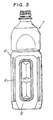
- Fig. 3 illustrates a conventional bottle-shaped container 1' having a square cylindrical body portion 2'. Each side surface of the body portion 2' continues to adjacent both side surfaces through ridge line portions, respectively. Each side surface of the body portion is provided with a reduced-pressure absorbing panel wall 3' for absorbing the deformation of the wall of the bottle-shaped container caused by the reduction of the pressure in the container.
- the panel walls 3' When the pressure in the bottle-shaped container 1' is reduced, the panel walls 3' is deformed and inwardly bent to cause an internal stress extended to the ridge line portions.
- the ridge portions are pillar portions for maintaining the shape of the bottle-shaped container and must have a high mechanical strength. If the ridge portions are deformed by the internal stress, the mode of bending of the panel walls 3' is not constant and the body portion of the square cylindrical shape is deformed.
- large bottle-shaped containers are greatly deformed by the reduced pressure, because the large bottle-shaped containers have a thin wall owing to a deep orientation and a large height thereof. Thus, the large bottle-shaped containers are required to have ridge line portions having a high mechanical strength.
- biaxially blow-molded bottle-shaped containers produced in a factory are packed in cases made of a corrugated cardboard and transported to other factories for filling liquid into the bottle-shaped containers.
- the bottle-shaped container is light, but is bulky. Consequently, in order to efficiently transport the bottle-shaped containers, it is desirable that a number of bottle-shaped containers are closely packed in each cardboard case.
- a biaxially blow-molded bottle-shaped container (1) of synthetic resin including a square cylindrical body portion (2), wherein a panel wall (3) for absorbing a reduced pressure generated in the bottle-shaped container is provided on a flat wall portion at each side of the body portion, and depressed cross grooves (5) are provided spaced apart in parallel by a constant distance in a ridge line portion between the adjacent panel walls (3, 3).
- the body portion may be cut-off at corners thereof to provide vertically elongated flat surfaces (4), and depressed cross grooves (5) may be provided spaced apart in parallel by a constant distance in each flat surface (4).
- the reduction of the pressure is sufficiently absorbed by elastic depression-deformation of the panel walls (3) of the body portion.
- the panel walls (3) are elastically depression-deformed to cause an internal stress, this internal stress acts to the ridge line portions between adjacent panel walls (3, 3').
- the internal stress consists of a component of force withdrawing inwardly the ridge line portions and a component of force pressing each ridge line portion from the opposite sides thereof.
- the cross grooves (5, 5) depressed in the ridge line portion will effect to inwardly bend the ridge line portion against the force withdrawing inwardly the ridge line portion.
- the ridge line portion is subjected to the withdrawing force as well as the pressing forces from the opposite sides thereof as mentioned above.
- the ridge line portion tends to protrude radially and outwardly owing to the forces pressing the ridge line portion from the opposite sides thereof.
- the ridge line portions act as reinforcing ribs against the withdrawing force and provide a high mechanical strength.
- the ridge line portions are elastically deformed inwardly all over the same owing to the cross grooves which are transversely depressed in the ridge line portion.
- the external pressing force is absorbed by the elastic bending-deformation of the ridge line portion all over the same.
- the deformed ridge line portions are elastically returned to the original form when the external pressing force is released. Accordingly the ridge line portions are not semi-permanently deformed.
- a corner of the body portion (2) may be cut-off to provide flat ridge line portions.
- each ridge line portion has corners (7) formed at its opposite sides and each cross groove (5) also has corners (7a) formed at its opposite sides.
- These corners (7 and 7a) arranged at the opposite sides of the each ridge line portion can act as reinforcing ribs against an elastic bent deformation of the central portion of the ridge line portion.
- the opposite side portions of the ridge line portion have a stress to extrude radially and outwardly from the ridge line portion by a force pressing the ridge portion from the opposite sides thereof due to the deformation of the panel wall.
- the function mechanically supporting the ridge line portion in the deformation of the panel wall is increased.
- the ridge line portion Since the central portion of the ridge line portion is flat, the ridge line portion can be elastically deformed by the external pressing force. Consequently, when the body portion of the bottle-shaped container which is not filled with liquid is subjected to a large external pressing force, the whole ridge line portion can be more greatly elastically deformed without semi-permanent bending-deformation and as a result the faculty of absorbing the external force is increased by the elastic deformation of the whole ridge line portions and also a sufficient mechanical strength to maintain the shape of the bottle-shaped container is sustained.
- a bottle-shaped container 1 is a large bottle having a thin wall which is produced by biaxially blow-molding a preformed parison made of a synthetic resin.
- the bottle-shaped container 1 is made of a polyethylene terephthalate resin.
- the bottle-shaped container 1 has a generally square cylindrical body portion 2. This body portion 2 is provided at each side of the container in about the two-third part of the lower portion thereof with panel walls 3 for absorbing deformation caused by reduced pressure in the container.
- Each panel wall 3 may be provided at its central portion with one or more depressed portions 3a which absorb the reduced pressure in the container.
- the depressed portion 3a effectively permits to deform the whole panel wall 3 owing to the reduced pressure without unduly straining.
- two depressed portions 3a, 3a are formed at positions vertically spaced apart in each panel wall on each side of the body portion, but an elongated depressed portion may be provided in each panel wall 3.
- a ridge line portion at each corner of the square cylindrical body portion 2 may be cut off to provide an elongated flat surface 4 which is vertically extended at each corner. Corner portions 7 are formed at the opposite sides of the flat surface 4.
- the flat surface 4 is provided with a plurality of depressed cross grooves 5 spaced apart in parallel.
- a cross ridge 6 is formed between adjacent cross grooves 5, 5 as a remained portion of the flat surface 4.
- the cross groove 5 is extended in the circumferential direction of the body portion over the width of the flat surface 4.
- the cross groove 5 has corners 7a formed therein. These corners 7a correspond to the corners 7, respectively.
- Vertical ribs 5a are formed between the opposite ends of the cross grooves and the corners 7a, respectively. The upper and lower ends of each cross groove 5 act as cross ribs 5b.
- the corners 7 and 7a continuously form a vertical rib which resists to an internal stress in the ridge line portion when the panel wall 3 absorbs the reduced pressure generated within the bottle-shaped container 1.
- the vertical ribs 5a and cross ribs 5b together with the cross ridge 6 absorb the external pressing force applied to the bottle-shaped container 1 to elastically deform the flat surface 4.
- the bottle-shaped container having the aforementioned construction according to the present invention can carry out the following effects.
- each ridge line portion stably and rigidly supports the panel wall which is elastically depression deformed owing to the reduced pressure to resist the internal stress caused by the depression-deformation of the panel wall, each panel wall for absorbing the reduced pressure in the bottle-shaped container is elastically depression-deformed. Accordingly, the configuration of the bottle-shaped container can be maintained in the better form when deforming due to the reduced pressure generated within the bottle-shaped container.
- the whole ridge line portions are greatly elastically deformed so that the external pressing force can be absorbed by the elastic deformation of the ridge line portions.
- the ridge line portions are not permanently deformed in the form of a buckling- or bending-deformation by the external pressing force to completely prevent occurring of a bottle-shaped container of inferior quality owing to the permanent buckling-deformation of the ridge line portions.
- the construction is simple and can be easily molded by the conventional manner without necessity of any particular molding technique.
Abstract
Description
- The present invention relates to a biaxially blow-molded bottle-shaped container made of synthetic resin, more particularly to a construction of a body portion of a biaxially blow-molded bottle-shaped container made of polyethylene terephthalate resin.
- There has hitherto been widely used a bottle-shaped container which is produced by biaxially blow-molding a preformed parison of synthetic resin such as polyethylene terephthalate resin. Such a bottle-shaped container has an excellent resistance to contents which is provided by sufficiently orienting the preformed parison. The bottle-shaped container is formed with a thin wall and light. The container has an excellent shock resistance and can be inexpensively produced by mass production.
- However, there is a problem that when the bottle-shaped container is filled with a hot liquid content and subsequently cooled, the wall of the body portion of the bottle-shaped container is deformed owing to a reduced pressure in the container.
- Accordingly, there has been known to provide panel walls in the body portion to absorb the reduced pressure by an elastic deformation of the panel walls. It is required that each panel wall is relatively large flat wall construction due to the following reasons. (1) By the reduced pressure, the panel wall is more deformable than the other of the body portion. (2) The depression deformation occurred on the panel wall is an elastic deformation. (3) Only a little depression-deformation decreases the volume of the container as large as possible.
- A large biaxially blow-molded bottle-shaped container having a cylindrical body portion of a circular section can be provided with reduced-pressure absorbing panels only by forming vertically extended flat portions on the peripheral surface portion of the body portion. Therefore, the shape of the panel walls on the body portion of the container is vertically elongated and as the result the panel walls of the container could not be greatly deformed. Therefore, the volume of the bottle-shaped container does not greatly vary by the depression-deformation of the panel walls on the body portion of the bottle-shaped container.
- While, a large biaxially blow-molded bottle-shaped container having a cylindrical body of a square section can be provided with reduced-pressure absorbing panels by forming a flat portion on each side of the square cylindrical body portion. Each flat portion can be easily and sufficiently deformed and has a large flat area so that the volume of the container can be greatly varied by the deformation of the flat portions. Thus, each flat portion effectively acts as a panel wall for absorbing the reduced pressure.
- Fig. 3 illustrates a conventional bottle-shaped container 1' having a square cylindrical body portion 2'. Each side surface of the body portion 2' continues to adjacent both side surfaces through ridge line portions, respectively. Each side surface of the body portion is provided with a reduced-pressure absorbing panel wall 3' for absorbing the deformation of the wall of the bottle-shaped container caused by the reduction of the pressure in the container.
- When the pressure in the bottle-shaped container 1' is reduced, the panel walls 3' is deformed and inwardly bent to cause an internal stress extended to the ridge line portions. The ridge portions are pillar portions for maintaining the shape of the bottle-shaped container and must have a high mechanical strength. If the ridge portions are deformed by the internal stress, the mode of bending of the panel walls 3' is not constant and the body portion of the square cylindrical shape is deformed. In particular, large bottle-shaped containers are greatly deformed by the reduced pressure, because the large bottle-shaped containers have a thin wall owing to a deep orientation and a large height thereof. Thus, the large bottle-shaped containers are required to have ridge line portions having a high mechanical strength.
- In order to eliminate the aforementioned problems, there has been designed to provide
elongated grooves 5' in the ridge line portions. Such anelongated groove 5' effects as a reinforcing rib to increase the mechanical strength in the ridge line portion to thereby prevent the ridge line portion from unduly strain deforming owing to the deformation of the panel wall 3'. - Generally, biaxially blow-molded bottle-shaped containers produced in a factory are packed in cases made of a corrugated cardboard and transported to other factories for filling liquid into the bottle-shaped containers. The bottle-shaped container is light, but is bulky. Consequently, in order to efficiently transport the bottle-shaped containers, it is desirable that a number of bottle-shaped containers are closely packed in each cardboard case.
- However, when uncapped bottle-shaped containers as shown in Fig. 3 are closely packed within the cardboard case and are subjected to an external pressing force over a limit of the resistance force of the ridge line portions having a mechanical strength sustained by the
elongated grooves 5', the ridge line portions are inwardly bent to occur a bending deformation. This bending-deformation is semi-permanently remained since theelongated grooves 5 effect as reinforcing ribs in the condition of bending deformation to prevent the ridge line portions from elastically returning back to the original form. - It is an object of the present invention to eliminate the aforementioned problems and disadvantages in the prior art and to provide a bottle-shaped container adapted for preventing the ridge line portions from inwardly bending and semi-permanently deforming by the external pressing force applied to the body portion of the bottle-shaped container, and also maintaining a necessary mechanical strength.
- According to the present invention, there is provided a biaxially blow-molded bottle-shaped container (1) of synthetic resin including a square cylindrical body portion (2), wherein a panel wall (3) for absorbing a reduced pressure generated in the bottle-shaped container is provided on a flat wall portion at each side of the body portion, and depressed cross grooves (5) are provided spaced apart in parallel by a constant distance in a ridge line portion between the adjacent panel walls (3, 3).
- The body portion may be cut-off at corners thereof to provide vertically elongated flat surfaces (4), and depressed cross grooves (5) may be provided spaced apart in parallel by a constant distance in each flat surface (4).
- When a pressure in the the bottle-shaped container is reduced by cooling after a hot liquid is filled in the container, the reduction of the pressure is sufficiently absorbed by elastic depression-deformation of the panel walls (3) of the body portion. When the panel walls (3) are elastically depression-deformed to cause an internal stress, this internal stress acts to the ridge line portions between adjacent panel walls (3, 3'). The internal stress consists of a component of force withdrawing inwardly the ridge line portions and a component of force pressing each ridge line portion from the opposite sides thereof.
- The cross grooves (5, 5) depressed in the ridge line portion will effect to inwardly bend the ridge line portion against the force withdrawing inwardly the ridge line portion. The ridge line portion is subjected to the withdrawing force as well as the pressing forces from the opposite sides thereof as mentioned above. The ridge line portion tends to protrude radially and outwardly owing to the forces pressing the ridge line portion from the opposite sides thereof. Thus, the ridge line portions act as reinforcing ribs against the withdrawing force and provide a high mechanical strength.
- Accordingly, when uncapped bottle-shaped containers (1) closely packed within the cardboard case are subjected to a force pressing sidewardly the body portion (2) and the pressing force increases higher than a predetermined value, the ridge line portions are elastically deformed inwardly all over the same owing to the cross grooves which are transversely depressed in the ridge line portion. Thus, the external pressing force is absorbed by the elastic bending-deformation of the ridge line portion all over the same. In this case, since the deformation of the ridge line portions is an elastic deformation, the deformed ridge line portions are elastically returned to the original form when the external pressing force is released. Accordingly the ridge line portions are not semi-permanently deformed.
- A corner of the body portion (2) may be cut-off to provide flat ridge line portions. Thus, each ridge line portion has corners (7) formed at its opposite sides and each cross groove (5) also has corners (7a) formed at its opposite sides. These corners (7 and 7a) arranged at the opposite sides of the each ridge line portion can act as reinforcing ribs against an elastic bent deformation of the central portion of the ridge line portion. Thus, the opposite side portions of the ridge line portion have a stress to extrude radially and outwardly from the ridge line portion by a force pressing the ridge portion from the opposite sides thereof due to the deformation of the panel wall. As a result, the function mechanically supporting the ridge line portion in the deformation of the panel wall is increased. Since the central portion of the ridge line portion is flat, the ridge line portion can be elastically deformed by the external pressing force. Consequently, when the body portion of the bottle-shaped container which is not filled with liquid is subjected to a large external pressing force, the whole ridge line portion can be more greatly elastically deformed without semi-permanent bending-deformation and as a result the faculty of absorbing the external force is increased by the elastic deformation of the whole ridge line portions and also a sufficient mechanical strength to maintain the shape of the bottle-shaped container is sustained.
-
- Fig. 1 is a front view of an embodiment of a biaxially blow-molded bottle-shaped container according to the present invention;
- Fig. 2 is an enlarged sectional view of the essential portion of the bottle-shaped container shown in Fig. 1; and
- Fig. 3 is a front view of conventional biaxially blow-molded bottle-shaped container of prior art.
- The preferred embodiment of the present invention will hereinafter be described with reference to the drawings.
- A bottle-shaped container 1 is a large bottle having a thin wall which is produced by biaxially blow-molding a preformed parison made of a synthetic resin. In this embodiment, the bottle-shaped container 1 is made of a polyethylene terephthalate resin.
- The bottle-shaped container 1 has a generally square
cylindrical body portion 2. Thisbody portion 2 is provided at each side of the container in about the two-third part of the lower portion thereof withpanel walls 3 for absorbing deformation caused by reduced pressure in the container. - Each
panel wall 3 may be provided at its central portion with one or moredepressed portions 3a which absorb the reduced pressure in the container. Thedepressed portion 3a effectively permits to deform thewhole panel wall 3 owing to the reduced pressure without unduly straining. In the illustrated embodiment, twodepressed portions panel wall 3. - Referring to Figs. 1 and 2, a ridge line portion at each corner of the square
cylindrical body portion 2 may be cut off to provide an elongated flat surface 4 which is vertically extended at each corner.Corner portions 7 are formed at the opposite sides of the flat surface 4. The flat surface 4 is provided with a plurality ofdepressed cross grooves 5 spaced apart in parallel. Across ridge 6 is formed betweenadjacent cross grooves cross groove 5 is extended in the circumferential direction of the body portion over the width of the flat surface 4. Thecross groove 5 hascorners 7a formed therein. Thesecorners 7a correspond to thecorners 7, respectively.Vertical ribs 5a are formed between the opposite ends of the cross grooves and thecorners 7a, respectively. The upper and lower ends of eachcross groove 5 act ascross ribs 5b. - The
corners panel wall 3 absorbs the reduced pressure generated within the bottle-shaped container 1. Thevertical ribs 5a and crossribs 5b together with thecross ridge 6 absorb the external pressing force applied to the bottle-shaped container 1 to elastically deform the flat surface 4. - The bottle-shaped container having the aforementioned construction according to the present invention can carry out the following effects.
- Since each ridge line portion stably and rigidly supports the panel wall which is elastically depression deformed owing to the reduced pressure to resist the internal stress caused by the depression-deformation of the panel wall, each panel wall for absorbing the reduced pressure in the bottle-shaped container is elastically depression-deformed. Accordingly, the configuration of the bottle-shaped container can be maintained in the better form when deforming due to the reduced pressure generated within the bottle-shaped container.
- When the body portion of the bottle-shaped container which is not filled with a content is subjected to a high external pressing force in the lateral direction, the whole ridge line portions are greatly elastically deformed so that the external pressing force can be absorbed by the elastic deformation of the ridge line portions. Thus, the ridge line portions are not permanently deformed in the form of a buckling- or bending-deformation by the external pressing force to completely prevent occurring of a bottle-shaped container of inferior quality owing to the permanent buckling-deformation of the ridge line portions.
- Since the ridge line portions in the corners of the square cylindrical body portion are provided with depressed cross grooves, fingers are snugly fitted in the cross grooves when the body portion is gripped by one hand. Therefore, such a large bottle-shaped container can be safely handled by one hand.
- Since the cross grooves are simply depressed in the ridge line portions, the construction is simple and can be easily molded by the conventional manner without necessity of any particular molding technique.
Claims (2)
- A biaxially blow-molded bottle-shaped container (1) of synthetic resin including a square cylindrical body portion (2), wherein
a panel wall (3) for absorbing a reduced pressure generated in the bottle-shaped container is provided on a flat wall portion at each side of the body portion, and
depressed cross grooves (5) are provided spaced apart in parallel in a ridge line portion between the adjacent panel walls (3, 3). - The biaxially blow-molded bottle-shaped container according to claim 1, wherein
the body portion is cut-off at corners thereof to provide vertically elongated flat surfaces (4), and
depressed cross grooves (5) are provided spaced apart in parallel in each flat surface (4).
Priority Applications (1)
| Application Number | Priority Date | Filing Date | Title |
|---|---|---|---|
| AT89910920T ATE114579T1 (en) | 1989-09-29 | 1989-09-29 | BIAXIALLY STRETCHED BLOW MOLDED BOTTLE. |
Applications Claiming Priority (3)
| Application Number | Priority Date | Filing Date | Title |
|---|---|---|---|
| JP1988044275U JPH084407Y2 (en) | 1988-04-01 | 1988-04-01 | Biaxial stretch blow molded bottle |
| PCT/JP1989/000988 WO1991004912A1 (en) | 1988-04-01 | 1989-09-29 | Biaxially stretched blow molded bottle |
| CA000614762A CA1334009C (en) | 1988-04-01 | 1989-09-29 | Biaxially blow-molded bottle-shaped container |
Publications (3)
| Publication Number | Publication Date |
|---|---|
| EP0446352A1 true EP0446352A1 (en) | 1991-09-18 |
| EP0446352A4 EP0446352A4 (en) | 1991-12-18 |
| EP0446352B1 EP0446352B1 (en) | 1994-11-30 |
Family
ID=25673170
Family Applications (1)
| Application Number | Title | Priority Date | Filing Date |
|---|---|---|---|
| EP89910920A Expired - Lifetime EP0446352B1 (en) | 1988-04-01 | 1989-09-29 | Biaxially stretched blow molded bottle |
Country Status (5)
| Country | Link |
|---|---|
| US (1) | US5199588A (en) |
| EP (1) | EP0446352B1 (en) |
| KR (1) | KR0154098B1 (en) |
| CA (1) | CA1334009C (en) |
| WO (1) | WO1991004912A1 (en) |
Cited By (8)
| Publication number | Priority date | Publication date | Assignee | Title |
|---|---|---|---|---|
| EP0616949A1 (en) * | 1993-03-26 | 1994-09-28 | Hoover Universal,Inc. | Hot fill plastic container having reinforced pressure absorption panels |
| WO1994025350A1 (en) * | 1993-04-27 | 1994-11-10 | Unilever Plc | Plastics container |
| WO1996001212A2 (en) * | 1994-07-05 | 1996-01-18 | Unifill S.P.A. | Container of thermoformable material with a closure |
| WO1997003885A1 (en) * | 1995-07-17 | 1997-02-06 | Continental Pet Technologies, Inc. | Pasteurizable plastic container |
| WO1999021770A1 (en) * | 1997-10-28 | 1999-05-06 | Continental Pet Technologies, Inc. | Hot-fillable plastic container with grippable body |
| WO2002044038A1 (en) * | 2000-11-29 | 2002-06-06 | Yoshino Kogyosho Co., Ltd. | Biaxially stretch-blow molded lightweight synthetic resin bottle container and method for production thereof |
| EP1339612A1 (en) * | 2000-06-30 | 2003-09-03 | PepsiCo, Inc. | Container with structural ribs |
| WO2006069292A1 (en) * | 2004-12-22 | 2006-06-29 | Graham Packaging Company, L.P. | Container having controlled top load characteristics |
Families Citing this family (105)
| Publication number | Priority date | Publication date | Assignee | Title |
|---|---|---|---|---|
| US5226550A (en) * | 1992-06-23 | 1993-07-13 | Silgan Plastics Corporation | Synthetic resin bottle with handgrips |
| JP3135995B2 (en) * | 1992-08-21 | 2001-02-19 | 株式会社吉野工業所 | Bottle |
| BR9303188A (en) * | 1993-09-02 | 1995-04-25 | Celbras Quimica E Textil S A | Plastic bottle for hot filling |
| CA2248957A1 (en) * | 1996-03-19 | 1997-09-25 | Graham Packaging Corporation | Blow-molded container having label mount regions separated by peripherally spaced ribs |
| US5762221A (en) * | 1996-07-23 | 1998-06-09 | Graham Packaging Corporation | Hot-fillable, blow-molded plastic container having a reinforced dome |
| US6092688A (en) * | 1998-05-06 | 2000-07-25 | Crown Cork & Seal Technologies Corporation | Drainage ports for plastic containers |
| US6223920B1 (en) * | 1998-05-19 | 2001-05-01 | Sclimalbach-Lubeca, Ag | Hot-fillable blow molded container with pinch-grip vacuum panels |
| US6164474A (en) | 1998-11-20 | 2000-12-26 | Crown Cork & Seal Technologies Corporation | Bottle with integrated grip portion |
| USD431465S (en) * | 1998-11-20 | 2000-10-03 | Crown Cork & Seal Technologies Corporation | Bottle with integrated grip portion |
| USD420587S (en) * | 1998-11-20 | 2000-02-15 | Crown Cork & Seal Technologies Corporation | Bottle with integrated grip portion |
| US6237792B1 (en) * | 1999-01-19 | 2001-05-29 | State Industrial Products | Reinforced bottle having integral handles |
| US6158620A (en) * | 1999-02-11 | 2000-12-12 | Chester Labs, Inc. | Collapsible container |
| CN1170737C (en) * | 1999-02-27 | 2004-10-13 | 株式会社吉野工业所 | Synthetic resin thin wall container |
| US6460714B1 (en) | 1999-03-29 | 2002-10-08 | Schmalbach-Lubeca Ag | Pasteurization panels for a plastic container |
| USD429164S (en) * | 1999-09-16 | 2000-08-08 | Ball Corporation | Plastic bottle including a grip portion |
| US6270488B1 (en) | 2000-01-24 | 2001-08-07 | Allegiance Corporation | Large volume medical fluid vacuum collection canister |
| USD448303S1 (en) | 2000-02-11 | 2001-09-25 | Crown Cork & Seal Technologies Corporation | Container |
| USD448672S1 (en) | 2000-02-11 | 2001-10-02 | Crown Cork & Seal Technologies Corporation | Container |
| USD448304S1 (en) | 2000-07-21 | 2001-09-25 | Crown Cork & Seal Technologies Corporation | Container |
| USD448302S1 (en) | 2000-07-21 | 2001-09-25 | Crown Cork & Seal Technologies Corporation | Container |
| US8584879B2 (en) * | 2000-08-31 | 2013-11-19 | Co2Pac Limited | Plastic container having a deep-set invertible base and related methods |
| US10246238B2 (en) | 2000-08-31 | 2019-04-02 | Co2Pac Limited | Plastic container having a deep-set invertible base and related methods |
| US7900425B2 (en) * | 2005-10-14 | 2011-03-08 | Graham Packaging Company, L.P. | Method for handling a hot-filled container having a moveable portion to reduce a portion of a vacuum created therein |
| TWI228476B (en) | 2000-08-31 | 2005-03-01 | Co2 Pac Ltd | Semi-rigid collapsible container |
| US8127955B2 (en) * | 2000-08-31 | 2012-03-06 | John Denner | Container structure for removal of vacuum pressure |
| US7543713B2 (en) | 2001-04-19 | 2009-06-09 | Graham Packaging Company L.P. | Multi-functional base for a plastic, wide-mouth, blow-molded container |
| US8381940B2 (en) * | 2002-09-30 | 2013-02-26 | Co2 Pac Limited | Pressure reinforced plastic container having a moveable pressure panel and related method of processing a plastic container |
| US10435223B2 (en) | 2000-08-31 | 2019-10-08 | Co2Pac Limited | Method of handling a plastic container having a moveable base |
| NZ521694A (en) | 2002-09-30 | 2005-05-27 | Co2 Pac Ltd | Container structure for removal of vacuum pressure |
| CA2368491C (en) * | 2001-01-22 | 2008-03-18 | Ocean Spray Cranberries, Inc. | Container with integrated grip portions |
| EP1387804A4 (en) | 2001-04-19 | 2005-03-02 | Graham Packaging Co | Multi-functional base for a plastic wide-mouth, blow-molded container |
| US7169418B2 (en) * | 2001-06-04 | 2007-01-30 | The Procter And Gamble Company | Packaging system to provide fresh packed coffee |
| WO2002098752A1 (en) | 2001-06-04 | 2002-12-12 | Crown Cork & Seal Technologies Corporation | Hot-fillable container with grip |
| USD486071S1 (en) | 2001-09-25 | 2004-02-03 | Constar International Inc. | Beverage bottle with hand grip |
| KR100730334B1 (en) * | 2001-09-27 | 2007-06-19 | 가부시키가이샤 요시노 고교쇼 | Synthetic resin container with shape retainability |
| JP3887753B2 (en) * | 2001-11-30 | 2007-02-28 | 株式会社吉野工業所 | Plastic container |
| US20030161980A1 (en) * | 2002-02-27 | 2003-08-28 | Nelson Brent S. | Plastic container |
| USD482287S1 (en) | 2002-05-10 | 2003-11-18 | Constar International, Inc. | Grippable bottle |
| US9969517B2 (en) | 2002-09-30 | 2018-05-15 | Co2Pac Limited | Systems and methods for handling plastic containers having a deep-set invertible base |
| WO2004052728A2 (en) * | 2002-12-05 | 2004-06-24 | Graham Packaging Company, L.P. | A rectangular container with cooperating vacuum panels and ribs on adjacent sides |
| US7882971B2 (en) * | 2002-12-05 | 2011-02-08 | Graham Packaging Company, L.P. | Rectangular container with vacuum panels |
| US9896233B2 (en) * | 2002-12-05 | 2018-02-20 | Graham Packaging Company, L.P. | Rectangular container having a vertically extending groove |
| US6920992B2 (en) * | 2003-02-10 | 2005-07-26 | Amcor Limited | Inverting vacuum panels for a plastic container |
| US7377399B2 (en) * | 2003-02-10 | 2008-05-27 | Amcor Limited | Inverting vacuum panels for a plastic container |
| US6935525B2 (en) * | 2003-02-14 | 2005-08-30 | Graham Packaging Company, L.P. | Container with flexible panels |
| RU2337863C2 (en) * | 2003-03-12 | 2008-11-10 | Констар Интернэшнл Инк. | Vessel with improved characteristic of top load effect |
| EP1651554B1 (en) * | 2003-07-30 | 2008-03-26 | Graham Packaging Company, L.P. | Container handling system |
| US7014056B2 (en) * | 2003-09-25 | 2006-03-21 | Graham Packaging Company, L.P. | 4-sided container with smooth front and back panels that can receive labels in a variety of ways |
| US20050139572A1 (en) * | 2003-12-29 | 2005-06-30 | Pedmo Marc A. | Plastic container |
| US7080747B2 (en) * | 2004-01-13 | 2006-07-25 | Amcor Limited | Lightweight container |
| CA2559319C (en) | 2004-03-11 | 2014-05-06 | Philip Sheets | Process and a device for conveying odd-shaped containers |
| US7347339B2 (en) * | 2004-04-01 | 2008-03-25 | Constar International, Inc. | Hot-fill bottle having flexible portions |
| US10611544B2 (en) | 2004-07-30 | 2020-04-07 | Co2Pac Limited | Method of handling a plastic container having a moveable base |
| GT200500274A (en) * | 2004-09-30 | 2009-05-22 | PRESSURE CONTAINER WITH DIFFERENTIAL VACUUM PANELS / PRESSURE CONTAINER WITH DIFFERENTIAL VACUUM PANELS | |
| US7823737B2 (en) * | 2005-02-02 | 2010-11-02 | Graham Packaging Company, L.P. | Plastic container with substantially flat panels |
| US8075833B2 (en) | 2005-04-15 | 2011-12-13 | Graham Packaging Company L.P. | Method and apparatus for manufacturing blow molded containers |
| US8017065B2 (en) * | 2006-04-07 | 2011-09-13 | Graham Packaging Company L.P. | System and method for forming a container having a grip region |
| JP5029859B2 (en) * | 2005-06-30 | 2012-09-19 | 株式会社吉野工業所 | Synthetic resin housing |
| US7455189B2 (en) * | 2005-08-22 | 2008-11-25 | Amcor Limited | Rectangular hot-filled container |
| US7857157B2 (en) * | 2006-01-25 | 2010-12-28 | Amcor Limited | Container having segmented bumper rib |
| US9707711B2 (en) * | 2006-04-07 | 2017-07-18 | Graham Packaging Company, L.P. | Container having outwardly blown, invertible deep-set grips |
| US8747727B2 (en) | 2006-04-07 | 2014-06-10 | Graham Packaging Company L.P. | Method of forming container |
| US8313005B2 (en) | 2006-08-03 | 2012-11-20 | Kraft Foods Global Brands, Llc | Plastic coffee container with pinch grip |
| US7472798B2 (en) * | 2006-08-15 | 2009-01-06 | Ball Corporation | Polygonal hour-glass hot-fillable bottle |
| US7581654B2 (en) * | 2006-08-15 | 2009-09-01 | Ball Corporation | Round hour-glass hot-fillable bottle |
| US7861876B2 (en) * | 2006-09-22 | 2011-01-04 | Ball Corporation | Bottle with intruding margin vacuum responsive panels |
| FR2907763B1 (en) * | 2006-10-27 | 2010-12-10 | Sidel Participations | CONTAINER, IN PARTICULAR BOTTLE, THERMOPLASTIC MATERIAL |
| US11897656B2 (en) | 2007-02-09 | 2024-02-13 | Co2Pac Limited | Plastic container having a movable base |
| US11731823B2 (en) | 2007-02-09 | 2023-08-22 | Co2Pac Limited | Method of handling a plastic container having a moveable base |
| US20100176081A1 (en) * | 2007-03-16 | 2010-07-15 | Constar International Inc. | Container having meta-stable panels |
| US7832583B2 (en) * | 2007-10-16 | 2010-11-16 | Graham Packaging Company, L.P. | Hot-fillable container and method of making |
| US20090232947A1 (en) * | 2008-03-14 | 2009-09-17 | Gerard Laurent Buisson | Packaging system to provide fresh packed coffee |
| US20090242505A1 (en) * | 2008-03-28 | 2009-10-01 | Constar International Inc. | Rectangular container having inset label panels and concave heel geometry |
| US20100006535A1 (en) * | 2008-07-09 | 2010-01-14 | Graham Packaging Company, L.P. | Plastic Container Possessing Improved Top Load Strength and Grippability |
| US8627944B2 (en) | 2008-07-23 | 2014-01-14 | Graham Packaging Company L.P. | System, apparatus, and method for conveying a plurality of containers |
| US8636944B2 (en) | 2008-12-08 | 2014-01-28 | Graham Packaging Company L.P. | Method of making plastic container having a deep-inset base |
| US7926243B2 (en) | 2009-01-06 | 2011-04-19 | Graham Packaging Company, L.P. | Method and system for handling containers |
| US8567622B2 (en) * | 2009-08-27 | 2013-10-29 | Graham Packaging Company, L.P. | Dome shaped hot-fill container |
| US8602237B2 (en) * | 2009-10-06 | 2013-12-10 | Graham Packaging Company, L.P. | Pasteurizable and hot-fillable blow molded plastic container |
| US8567623B2 (en) * | 2009-10-15 | 2013-10-29 | Graham Packaging Company, L.P. | Hot-fill container having a tapered body and dome |
| US10183779B2 (en) * | 2010-01-18 | 2019-01-22 | Graham Packaging Company, L.P. | Container for storing motor vehicle fluid |
| US8962114B2 (en) | 2010-10-30 | 2015-02-24 | Graham Packaging Company, L.P. | Compression molded preform for forming invertible base hot-fill container, and systems and methods thereof |
| US9133006B2 (en) | 2010-10-31 | 2015-09-15 | Graham Packaging Company, L.P. | Systems, methods, and apparatuses for cooling hot-filled containers |
| US10829260B2 (en) | 2010-11-12 | 2020-11-10 | Niagara Bottling, Llc | Preform extended finish for processing light weight ecologically beneficial bottles |
| US10118724B2 (en) | 2010-11-12 | 2018-11-06 | Niagara Bottling, Llc | Preform extended finish for processing light weight ecologically beneficial bottles |
| US10647465B2 (en) | 2010-11-12 | 2020-05-12 | Niagara Bottling, Llc | Perform extended finish for processing light weight ecologically beneficial bottles |
| RU2013123905A (en) | 2010-11-12 | 2014-12-20 | Ниагара Боттлинг, Ллс. | EXTENDED END OF THE PREFORMA FOR THE PRODUCTION OF BOTTLES OF LOW WEIGHT |
| US8505757B2 (en) * | 2011-02-16 | 2013-08-13 | Amcor Limited | Shoulder rib to direct top load force |
| US8556097B2 (en) * | 2011-02-16 | 2013-10-15 | Amcor Limited | Container having vacuum panel with balanced vacuum and pressure response |
| US8863970B2 (en) | 2011-05-25 | 2014-10-21 | Graham Packaging Company, L.P. | Plastic container with anti-bulge panel |
| US9150320B2 (en) | 2011-08-15 | 2015-10-06 | Graham Packaging Company, L.P. | Plastic containers having base configurations with up-stand walls having a plurality of rings, and systems, methods, and base molds thereof |
| US9994378B2 (en) | 2011-08-15 | 2018-06-12 | Graham Packaging Company, L.P. | Plastic containers, base configurations for plastic containers, and systems, methods, and base molds thereof |
| US8919587B2 (en) | 2011-10-03 | 2014-12-30 | Graham Packaging Company, L.P. | Plastic container with angular vacuum panel and method of same |
| JP6521634B2 (en) | 2011-12-05 | 2019-05-29 | ナイアガラ・ボトリング・エルエルシー | Plastic container with ribs of varying depth |
| US11845581B2 (en) | 2011-12-05 | 2023-12-19 | Niagara Bottling, Llc | Swirl bell bottle with wavy ribs |
| US10023346B2 (en) | 2012-12-27 | 2018-07-17 | Niagara Bottling, Llc | Swirl bell bottle with wavy ribs |
| US8991441B2 (en) * | 2012-03-02 | 2015-03-31 | Graham Packaging Company, L.P. | Hot-fillable container with moveable panel and systems and methods thereof |
| EP2938548B1 (en) | 2012-12-27 | 2017-02-22 | Niagara Bottling, LLC | Plastic container with stiffening ribs |
| US9022776B2 (en) | 2013-03-15 | 2015-05-05 | Graham Packaging Company, L.P. | Deep grip mechanism within blow mold hanger and related methods and bottles |
| US9254937B2 (en) | 2013-03-15 | 2016-02-09 | Graham Packaging Company, L.P. | Deep grip mechanism for blow mold and related methods and bottles |
| USD699116S1 (en) | 2013-05-07 | 2014-02-11 | Niagara Bottling, Llc | Plastic container |
| USD696126S1 (en) | 2013-05-07 | 2013-12-24 | Niagara Bottling, Llc | Plastic container |
| USD699115S1 (en) | 2013-05-07 | 2014-02-11 | Niagara Bottling, Llc | Plastic container |
| US11597556B2 (en) | 2018-07-30 | 2023-03-07 | Niagara Bottling, Llc | Container preform with tamper evidence finish portion |
| US11913600B2 (en) * | 2020-10-30 | 2024-02-27 | Khurram Raza | Shaped bottle with attachment feature |
Citations (1)
| Publication number | Priority date | Publication date | Assignee | Title |
|---|---|---|---|---|
| EP0324305A1 (en) * | 1988-01-14 | 1989-07-19 | Sidel | Bottle of thermoplastic material |
Family Cites Families (9)
| Publication number | Priority date | Publication date | Assignee | Title |
|---|---|---|---|---|
| FR1351140A (en) * | 1963-03-14 | 1964-01-31 | Process for manufacturing flexible plastic containers, such as bottles, as well as the molds necessary for obtaining these containers and the products conforming to those obtained by applying the preceding process or similar process | |
| FR1397037A (en) * | 1964-05-26 | 1965-04-23 | Unipol S A Soc | Capacity constituting a packaging for fluid products |
| DE2635494A1 (en) * | 1976-08-06 | 1978-03-02 | Ristic Zoran | Space-saving plastics bottle for carbonated beverages - has square cross-section and tapering middle and top sections |
| JPH0423765Y2 (en) * | 1984-09-06 | 1992-06-03 | ||
| JPS61117109A (en) * | 1984-11-09 | 1986-06-04 | Kawasaki Steel Corp | Preparation of impregnating pitch for electrode |
| CA1282018C (en) * | 1985-04-17 | 1991-03-26 | Akiho Ota | Biaxial-orientation blow-molded bottle-shaped container |
| JPH0626532B2 (en) * | 1985-10-04 | 1994-04-13 | 松下電器産業株式会社 | Electric coffee heater |
| JPH0331692Y2 (en) * | 1985-11-14 | 1991-07-05 | ||
| US4863046A (en) * | 1987-12-24 | 1989-09-05 | Continental Pet Technologies, Inc. | Hot fill container |
-
1989
- 1989-09-29 WO PCT/JP1989/000988 patent/WO1991004912A1/en active IP Right Grant
- 1989-09-29 CA CA000614762A patent/CA1334009C/en not_active Expired - Fee Related
- 1989-09-29 KR KR1019900700450A patent/KR0154098B1/en not_active IP Right Cessation
- 1989-09-29 US US07/465,227 patent/US5199588A/en not_active Expired - Lifetime
- 1989-09-29 EP EP89910920A patent/EP0446352B1/en not_active Expired - Lifetime
Patent Citations (1)
| Publication number | Priority date | Publication date | Assignee | Title |
|---|---|---|---|---|
| EP0324305A1 (en) * | 1988-01-14 | 1989-07-19 | Sidel | Bottle of thermoplastic material |
Non-Patent Citations (1)
| Title |
|---|
| See also references of WO9104912A1 * |
Cited By (15)
| Publication number | Priority date | Publication date | Assignee | Title |
|---|---|---|---|---|
| EP0616949A1 (en) * | 1993-03-26 | 1994-09-28 | Hoover Universal,Inc. | Hot fill plastic container having reinforced pressure absorption panels |
| WO1994025350A1 (en) * | 1993-04-27 | 1994-11-10 | Unilever Plc | Plastics container |
| US5499730A (en) * | 1993-04-27 | 1996-03-19 | Lever Brothers Company | Plastic container having reinforcing depressions |
| WO1996001212A2 (en) * | 1994-07-05 | 1996-01-18 | Unifill S.P.A. | Container of thermoformable material with a closure |
| WO1996001212A3 (en) * | 1994-07-05 | 1996-03-07 | Unifill Spa | Container of thermoformable material with a closure |
| US5908128A (en) * | 1995-07-17 | 1999-06-01 | Continental Pet Technologies, Inc. | Pasteurizable plastic container |
| WO1997003885A1 (en) * | 1995-07-17 | 1997-02-06 | Continental Pet Technologies, Inc. | Pasteurizable plastic container |
| WO1999021770A1 (en) * | 1997-10-28 | 1999-05-06 | Continental Pet Technologies, Inc. | Hot-fillable plastic container with grippable body |
| US5971184A (en) * | 1997-10-28 | 1999-10-26 | Continental Pet Technologies, Inc. | Hot-fillable plastic container with grippable body |
| EP1339612A1 (en) * | 2000-06-30 | 2003-09-03 | PepsiCo, Inc. | Container with structural ribs |
| EP1339612A4 (en) * | 2000-06-30 | 2004-03-17 | Pepsico Inc | Container with structural ribs |
| US7032770B2 (en) | 2000-06-30 | 2006-04-25 | Pepsico, Inc. | Container with structural ribs |
| WO2002044038A1 (en) * | 2000-11-29 | 2002-06-06 | Yoshino Kogyosho Co., Ltd. | Biaxially stretch-blow molded lightweight synthetic resin bottle container and method for production thereof |
| WO2006069292A1 (en) * | 2004-12-22 | 2006-06-29 | Graham Packaging Company, L.P. | Container having controlled top load characteristics |
| US7374055B2 (en) | 2004-12-22 | 2008-05-20 | Graham Packaging Company, L.P. | Container having controlled top load characteristics |
Also Published As
| Publication number | Publication date |
|---|---|
| US5199588A (en) | 1993-04-06 |
| CA1334009C (en) | 1995-01-17 |
| KR920700145A (en) | 1992-02-19 |
| KR0154098B1 (en) | 1999-02-18 |
| WO1991004912A1 (en) | 1991-04-18 |
| EP0446352B1 (en) | 1994-11-30 |
| EP0446352A4 (en) | 1991-12-18 |
Similar Documents
| Publication | Publication Date | Title |
|---|---|---|
| US5199588A (en) | Biaxially blow-molded bottle-shaped container having pressure responsive walls | |
| CA2508753C (en) | A rectangular container with cooperating vacuum panels and ribs on adjacent sides | |
| EP0695263B1 (en) | Plastics container | |
| US4993565A (en) | Biaxial-orientation blow-molded bottle-shaped container having opposed recesses and grooves for stable gripping and anti-buckling stiffness | |
| US7073675B2 (en) | Container with deflectable panels | |
| US5148930A (en) | Biaxial-orientation blow-molded bottle-shaped container having opposed recesses and grooves for stable gripping and anti-buckling stiffness | |
| US6981604B2 (en) | Synthetic resin container having a body with concaved portion for gripping and absorbing distortion of the body | |
| US4775564A (en) | Collapsible-stable blown container | |
| EP1574439B1 (en) | Synthetic resin container having improved shape stability | |
| US20060151425A1 (en) | Rectangular container with vacuum panels | |
| EP1431191B1 (en) | Bottle container | |
| US20090095702A1 (en) | Hot-fillable container and method of making | |
| WO2003076279A1 (en) | Plastic container having depressed grip sections | |
| EP1459991B1 (en) | Synthetic resin container | |
| JP2905838B2 (en) | Synthetic resin bottle | |
| JPH0589214U (en) | Bottle made of synthetic resin | |
| AU647375B2 (en) | Biaxially stretched blow molded bottle | |
| JP3490701B2 (en) | PET bottle container with means for responding to changes in internal pressure | |
| JP3544706B2 (en) | Biaxial stretch blow molded container | |
| JP2949459B2 (en) | Hollow container made of polyethylene terephthalate resin | |
| JP2017214117A (en) | Blow molded container | |
| CN1022820C (en) | Jar formed with biaxial stretching blow moulding | |
| JPH08224U (en) | Bottle made of synthetic resin | |
| JP4287203B2 (en) | Synthetic resin housing |
Legal Events
| Date | Code | Title | Description |
|---|---|---|---|
| PUAI | Public reference made under article 153(3) epc to a published international application that has entered the european phase |
Free format text: ORIGINAL CODE: 0009012 |
|
| 17P | Request for examination filed |
Effective date: 19910610 |
|
| AK | Designated contracting states |
Kind code of ref document: A1 Designated state(s): AT BE CH DE FR GB IT LI NL |
|
| A4 | Supplementary search report drawn up and despatched |
Effective date: 19911031 |
|
| AK | Designated contracting states |
Kind code of ref document: A4 Designated state(s): AT BE CH DE FR GB IT LI NL |
|
| 17Q | First examination report despatched |
Effective date: 19930119 |
|
| GRAA | (expected) grant |
Free format text: ORIGINAL CODE: 0009210 |
|
| AK | Designated contracting states |
Kind code of ref document: B1 Designated state(s): AT BE CH DE FR GB IT LI NL |
|
| REF | Corresponds to: |
Ref document number: 114579 Country of ref document: AT Date of ref document: 19941215 Kind code of ref document: T |
|
| ITF | It: translation for a ep patent filed |
Owner name: STUDIO FERRARIO |
|
| REF | Corresponds to: |
Ref document number: 68919710 Country of ref document: DE Date of ref document: 19950112 |
|
| ET | Fr: translation filed | ||
| PLBE | No opposition filed within time limit |
Free format text: ORIGINAL CODE: 0009261 |
|
| STAA | Information on the status of an ep patent application or granted ep patent |
Free format text: STATUS: NO OPPOSITION FILED WITHIN TIME LIMIT |
|
| 26N | No opposition filed | ||
| PGFP | Annual fee paid to national office [announced via postgrant information from national office to epo] |
Ref country code: AT Payment date: 20000929 Year of fee payment: 12 |
|
| PGFP | Annual fee paid to national office [announced via postgrant information from national office to epo] |
Ref country code: NL Payment date: 20010927 Year of fee payment: 13 |
|
| PG25 | Lapsed in a contracting state [announced via postgrant information from national office to epo] |
Ref country code: AT Free format text: LAPSE BECAUSE OF NON-PAYMENT OF DUE FEES Effective date: 20010929 |
|
| PGFP | Annual fee paid to national office [announced via postgrant information from national office to epo] |
Ref country code: CH Payment date: 20011015 Year of fee payment: 13 |
|
| PGFP | Annual fee paid to national office [announced via postgrant information from national office to epo] |
Ref country code: BE Payment date: 20011116 Year of fee payment: 13 |
|
| REG | Reference to a national code |
Ref country code: GB Ref legal event code: IF02 |
|
| PG25 | Lapsed in a contracting state [announced via postgrant information from national office to epo] |
Ref country code: CH Free format text: LAPSE BECAUSE OF NON-PAYMENT OF DUE FEES Effective date: 20020930 Ref country code: LI Free format text: LAPSE BECAUSE OF NON-PAYMENT OF DUE FEES Effective date: 20020930 Ref country code: BE Free format text: LAPSE BECAUSE OF NON-PAYMENT OF DUE FEES Effective date: 20020930 |
|
| BERE | Be: lapsed |
Owner name: *YOSHINO KOGYOSHO CO. LTD Effective date: 20020930 |
|
| PG25 | Lapsed in a contracting state [announced via postgrant information from national office to epo] |
Ref country code: NL Free format text: LAPSE BECAUSE OF NON-PAYMENT OF DUE FEES Effective date: 20030401 |
|
| REG | Reference to a national code |
Ref country code: CH Ref legal event code: PL |
|
| PGFP | Annual fee paid to national office [announced via postgrant information from national office to epo] |
Ref country code: GB Payment date: 20050928 Year of fee payment: 17 |
|
| PG25 | Lapsed in a contracting state [announced via postgrant information from national office to epo] |
Ref country code: IT Free format text: LAPSE BECAUSE OF NON-PAYMENT OF DUE FEES;WARNING: LAPSES OF ITALIAN PATENTS WITH EFFECTIVE DATE BEFORE 2007 MAY HAVE OCCURRED AT ANY TIME BEFORE 2007. THE CORRECT EFFECTIVE DATE MAY BE DIFFERENT FROM THE ONE RECORDED. Effective date: 20050929 |
|
| PGFP | Annual fee paid to national office [announced via postgrant information from national office to epo] |
Ref country code: FR Payment date: 20060908 Year of fee payment: 18 |
|
| PGFP | Annual fee paid to national office [announced via postgrant information from national office to epo] |
Ref country code: DE Payment date: 20060922 Year of fee payment: 18 |
|
| GBPC | Gb: european patent ceased through non-payment of renewal fee |
Effective date: 20060929 |
|
| PG25 | Lapsed in a contracting state [announced via postgrant information from national office to epo] |
Ref country code: GB Free format text: LAPSE BECAUSE OF NON-PAYMENT OF DUE FEES Effective date: 20060929 |
|
| PG25 | Lapsed in a contracting state [announced via postgrant information from national office to epo] |
Ref country code: DE Free format text: LAPSE BECAUSE OF NON-PAYMENT OF DUE FEES Effective date: 20080401 |
|
| REG | Reference to a national code |
Ref country code: FR Ref legal event code: ST Effective date: 20080531 |
|
| PG25 | Lapsed in a contracting state [announced via postgrant information from national office to epo] |
Ref country code: FR Free format text: LAPSE BECAUSE OF NON-PAYMENT OF DUE FEES Effective date: 20071001 |