EP0446365A1 - Water discharging apparatus - Google Patents
Water discharging apparatus Download PDFInfo
- Publication number
- EP0446365A1 EP0446365A1 EP19900913867 EP90913867A EP0446365A1 EP 0446365 A1 EP0446365 A1 EP 0446365A1 EP 19900913867 EP19900913867 EP 19900913867 EP 90913867 A EP90913867 A EP 90913867A EP 0446365 A1 EP0446365 A1 EP 0446365A1
- Authority
- EP
- European Patent Office
- Prior art keywords
- water
- light emitting
- light
- outlet port
- emitting device
- Prior art date
- Legal status (The legal status is an assumption and is not a legal conclusion. Google has not performed a legal analysis and makes no representation as to the accuracy of the status listed.)
- Withdrawn
Links
- XLYOFNOQVPJJNP-UHFFFAOYSA-N water Substances O XLYOFNOQVPJJNP-UHFFFAOYSA-N 0.000 title claims abstract description 202
- 238000007599 discharging Methods 0.000 title claims abstract description 23
- 239000013307 optical fiber Substances 0.000 claims abstract description 20
- 230000004044 response Effects 0.000 claims description 15
- 238000001914 filtration Methods 0.000 claims description 12
- 230000001678 irradiating effect Effects 0.000 abstract 1
- 239000008213 purified water Substances 0.000 description 33
- 239000008399 tap water Substances 0.000 description 13
- 235000020679 tap water Nutrition 0.000 description 13
- OKTJSMMVPCPJKN-UHFFFAOYSA-N Carbon Chemical compound [C] OKTJSMMVPCPJKN-UHFFFAOYSA-N 0.000 description 6
- 239000012629 purifying agent Substances 0.000 description 5
- WABPQHHGFIMREM-UHFFFAOYSA-N lead(0) Chemical compound [Pb] WABPQHHGFIMREM-UHFFFAOYSA-N 0.000 description 3
- VTYYLEPIZMXCLO-UHFFFAOYSA-L Calcium carbonate Chemical compound [Ca+2].[O-]C([O-])=O VTYYLEPIZMXCLO-UHFFFAOYSA-L 0.000 description 2
- 239000003086 colorant Substances 0.000 description 2
- GPRLSGONYQIRFK-UHFFFAOYSA-N hydron Chemical compound [H+] GPRLSGONYQIRFK-UHFFFAOYSA-N 0.000 description 2
- 239000000203 mixture Substances 0.000 description 2
- 238000005192 partition Methods 0.000 description 2
- ZAMOUSCENKQFHK-UHFFFAOYSA-N Chlorine atom Chemical compound [Cl] ZAMOUSCENKQFHK-UHFFFAOYSA-N 0.000 description 1
- 229910000019 calcium carbonate Inorganic materials 0.000 description 1
- 239000000460 chlorine Substances 0.000 description 1
- 229910052801 chlorine Inorganic materials 0.000 description 1
- 230000025508 response to water Effects 0.000 description 1
Images


Classifications
-
- G—PHYSICS
- G01—MEASURING; TESTING
- G01N—INVESTIGATING OR ANALYSING MATERIALS BY DETERMINING THEIR CHEMICAL OR PHYSICAL PROPERTIES
- G01N33/00—Investigating or analysing materials by specific methods not covered by groups G01N1/00 - G01N31/00
- G01N33/18—Water
- G01N33/1813—Water specific cations in water, e.g. heavy metals
-
- E—FIXED CONSTRUCTIONS
- E03—WATER SUPPLY; SEWERAGE
- E03C—DOMESTIC PLUMBING INSTALLATIONS FOR FRESH WATER OR WASTE WATER; SINKS
- E03C1/00—Domestic plumbing installations for fresh water or waste water; Sinks
- E03C1/02—Plumbing installations for fresh water
- E03C1/04—Water-basin installations specially adapted to wash-basins or baths
- E03C1/0404—Constructional or functional features of the spout
-
- F—MECHANICAL ENGINEERING; LIGHTING; HEATING; WEAPONS; BLASTING
- F21—LIGHTING
- F21V—FUNCTIONAL FEATURES OR DETAILS OF LIGHTING DEVICES OR SYSTEMS THEREOF; STRUCTURAL COMBINATIONS OF LIGHTING DEVICES WITH OTHER ARTICLES, NOT OTHERWISE PROVIDED FOR
- F21V33/00—Structural combinations of lighting devices with other articles, not otherwise provided for
- F21V33/0004—Personal or domestic articles
- F21V33/004—Sanitary equipment, e.g. mirrors, showers, toilet seats or paper dispensers
-
- G—PHYSICS
- G01—MEASURING; TESTING
- G01D—MEASURING NOT SPECIALLY ADAPTED FOR A SPECIFIC VARIABLE; ARRANGEMENTS FOR MEASURING TWO OR MORE VARIABLES NOT COVERED IN A SINGLE OTHER SUBCLASS; TARIFF METERING APPARATUS; MEASURING OR TESTING NOT OTHERWISE PROVIDED FOR
- G01D5/00—Mechanical means for transferring the output of a sensing member; Means for converting the output of a sensing member to another variable where the form or nature of the sensing member does not constrain the means for converting; Transducers not specially adapted for a specific variable
- G01D5/26—Mechanical means for transferring the output of a sensing member; Means for converting the output of a sensing member to another variable where the form or nature of the sensing member does not constrain the means for converting; Transducers not specially adapted for a specific variable characterised by optical transfer means, i.e. using infrared, visible, or ultraviolet light
- G01D5/268—Mechanical means for transferring the output of a sensing member; Means for converting the output of a sensing member to another variable where the form or nature of the sensing member does not constrain the means for converting; Transducers not specially adapted for a specific variable characterised by optical transfer means, i.e. using infrared, visible, or ultraviolet light using optical fibres
-
- G—PHYSICS
- G01—MEASURING; TESTING
- G01K—MEASURING TEMPERATURE; MEASURING QUANTITY OF HEAT; THERMALLY-SENSITIVE ELEMENTS NOT OTHERWISE PROVIDED FOR
- G01K13/00—Thermometers specially adapted for specific purposes
- G01K13/02—Thermometers specially adapted for specific purposes for measuring temperature of moving fluids or granular materials capable of flow
-
- G—PHYSICS
- G01—MEASURING; TESTING
- G01N—INVESTIGATING OR ANALYSING MATERIALS BY DETERMINING THEIR CHEMICAL OR PHYSICAL PROPERTIES
- G01N33/00—Investigating or analysing materials by specific methods not covered by groups G01N1/00 - G01N31/00
- G01N33/18—Water
-
- G—PHYSICS
- G01—MEASURING; TESTING
- G01N—INVESTIGATING OR ANALYSING MATERIALS BY DETERMINING THEIR CHEMICAL OR PHYSICAL PROPERTIES
- G01N33/00—Investigating or analysing materials by specific methods not covered by groups G01N1/00 - G01N31/00
- G01N33/18—Water
- G01N33/1853—Water hardness of water
-
- G—PHYSICS
- G01—MEASURING; TESTING
- G01P—MEASURING LINEAR OR ANGULAR SPEED, ACCELERATION, DECELERATION, OR SHOCK; INDICATING PRESENCE, ABSENCE, OR DIRECTION, OF MOVEMENT
- G01P13/00—Indicating or recording presence, absence, or direction, of movement
- G01P13/0006—Indicating or recording presence, absence, or direction, of movement of fluids or of granulous or powder-like substances
-
- E—FIXED CONSTRUCTIONS
- E03—WATER SUPPLY; SEWERAGE
- E03C—DOMESTIC PLUMBING INSTALLATIONS FOR FRESH WATER OR WASTE WATER; SINKS
- E03C1/00—Domestic plumbing installations for fresh water or waste water; Sinks
- E03C1/02—Plumbing installations for fresh water
- E03C1/04—Water-basin installations specially adapted to wash-basins or baths
- E03C2001/0418—Water-basin installations specially adapted to wash-basins or baths having temperature indicating means
-
- E—FIXED CONSTRUCTIONS
- E03—WATER SUPPLY; SEWERAGE
- E03C—DOMESTIC PLUMBING INSTALLATIONS FOR FRESH WATER OR WASTE WATER; SINKS
- E03C2201/00—Details, devices or methods not otherwise provided for
- E03C2201/40—Arrangement of water treatment devices in domestic plumbing installations
-
- F—MECHANICAL ENGINEERING; LIGHTING; HEATING; WEAPONS; BLASTING
- F21—LIGHTING
- F21V—FUNCTIONAL FEATURES OR DETAILS OF LIGHTING DEVICES OR SYSTEMS THEREOF; STRUCTURAL COMBINATIONS OF LIGHTING DEVICES WITH OTHER ARTICLES, NOT OTHERWISE PROVIDED FOR
- F21V2200/00—Use of light guides, e.g. fibre optic devices, in lighting devices or systems
- F21V2200/10—Use of light guides, e.g. fibre optic devices, in lighting devices or systems of light guides of the optical fibres type
-
- Y—GENERAL TAGGING OF NEW TECHNOLOGICAL DEVELOPMENTS; GENERAL TAGGING OF CROSS-SECTIONAL TECHNOLOGIES SPANNING OVER SEVERAL SECTIONS OF THE IPC; TECHNICAL SUBJECTS COVERED BY FORMER USPC CROSS-REFERENCE ART COLLECTIONS [XRACs] AND DIGESTS
- Y10—TECHNICAL SUBJECTS COVERED BY FORMER USPC
- Y10S—TECHNICAL SUBJECTS COVERED BY FORMER USPC CROSS-REFERENCE ART COLLECTIONS [XRACs] AND DIGESTS
- Y10S362/00—Illumination
- Y10S362/80—Light emitting diode
-
- Y—GENERAL TAGGING OF NEW TECHNOLOGICAL DEVELOPMENTS; GENERAL TAGGING OF CROSS-SECTIONAL TECHNOLOGIES SPANNING OVER SEVERAL SECTIONS OF THE IPC; TECHNICAL SUBJECTS COVERED BY FORMER USPC CROSS-REFERENCE ART COLLECTIONS [XRACs] AND DIGESTS
- Y10—TECHNICAL SUBJECTS COVERED BY FORMER USPC
- Y10T—TECHNICAL SUBJECTS COVERED BY FORMER US CLASSIFICATION
- Y10T137/00—Fluid handling
- Y10T137/8158—With indicator, register, recorder, alarm or inspection means
- Y10T137/8225—Position or extent of motion indicator
- Y10T137/8259—Selection from plural branches
Definitions
- a purified water outlet 60A extends centrally from the bottom of the purified water cartridge 60.
- a unpurified water inlet 60B is defined coaxially around the purified water outlet 60A.
- the purified water cartridge 60 includes a filtering element 60C such as an activated carbon.
- the shower outlets 108 are also communicated with the passage 70.
Abstract
Description
- The present invention relates to an apparatus for discharging water such as a water faucet and in particular, to an apparatus constructed to emit light to output water in response to the temperature, quality, pressure or volume of water.
- There has been proposed an automatic faucet wherein a switch is operable to change the volume or temperature of the output water. A lamp is turned on and off so that a user may visually recognize the volume or temperature of water.
- It is well known that a water purifier includes a purifying agent such as an activated carbon to purify tap water. The water purifier typically includes a changeover valve operable to selectively discharge tap water and purified water. A lamp is turned on when the changeover valve is operated to provide purified water. A sensor (for example, conductance meter) is provided to detect the quality of purified water, and a warning lamp is turned on when the quality of the purified water deteriorates. A similar warning lamp is turned on when the volume of water flowing through the purifying agent exceeds a predetermined level.
- Those lamps are often placed in a control box which is separated from a water faucet. In some case, the lamps are mounted to a faucet, but to the upper portion of the faucet, so that water hardly splashes the lamps. A disadvantage with this arrangement is that the user can not easily view the lamps.
- According to one aspect of the invention, there is provided an apparatus for discharging water comprising a water passageway, characterized by sensor means for sensing characteristics of water flowing through the water passageway, and light emitting means for emitting light to the water passageway or a region downstream of the water passageway in response to the characteristics as sensed.
- In the apparatus of the present invention, the characteristics includes one or more of the following: water temperature, water flow, water pressure and water concentration.
- In the apparatus of the present invention, the water concentration is pH and/or hardness.
- According to another aspect of the invention, there is provided an apparatus for discharging water including an outlet port, a plurality of feed water passages connected to the outlet port, and passage selection means for selectively communicating the outlet port with either one of the plurality of feed water passages, characterized by sensor means for sensing which one of the plurality of feed water passages is selected by the passage selection means, and light emitting means for emitting light to the feed water passage or a region through which water flows from the outlet port in response to the sensing by the sensor means.
- In this case, a filtering element is disposed in either one of the feed water passages.
- According to a further aspect of the invention, there is provided an apparatus for discharging water including a filtering element, characterized by sensor means disposed downstream of the filtering element for sensing the quality of water, and light emitting means for emitting light to a passage in the apparatus or a region through which the water flows from an outlet port in response to the sensing by the sensor means.
- According to a still further aspect of the invention, there is provided an apparatus for discharging water including a filtering element, characterized by sensor means for sensing integrated flow of water flowing through the filtering element, and light emitting means for emitting light to a passage in the apparatus or a region through which the water flows from an outlet port in response to the integrated flow as sensed.
- In the apparatus of the present invention, the light emitting means comprises a light emitting device and an optical fiber for guiding light from the light emitting device. Of course, any light emitting device other than LED and any light transmitter other than the optical fiber may be used.
- In the present invention, in order to sense a selected one of the passages in the apparatus, a sensor or switch may be used to sense angular position of a handle or valve of the present apparatus. Also, in the present invention, a motor or solenoid is used to change passages, and an electric switch is used to select a desired passage. In such a case, light may be emitted in response to a signal from the electric switch.
- In the apparatus of the present invention, since color light is emitted to the output water, the user may view the water as if it is colored. The user almost always views the output water when the water faucet is in use. As such, the user can visually identify water volume or temperature.
- According to the present invention, light is emitted to the output water in response to the temperature, flow rate, pressure, pH (hydrogen ion concentration), and hardness of water.
- According to another aspect of the invention, light is emitted to water in response to integrated flow of water flowing through the filtering element.
- In the present invention, in order to sense a selected one of the passages in the apparatus, a sensor or switch may be used to sense angular position of a handle or valve of the present apparatus. Also, in the present invention, a motor or solenoid is used to change passages, and an electric switch is used to select a desired passage. In such a case, light may be emitted in response to a signal from the electric switch.
- In the present invention, the color of output light may be varied in response to the temperature, volume, pressure, pH or hardness of the output water. For example, blue light is emitted when the output water has a temperature of lower than 20° . Red light is emitted when the output water has a temperature of higher than 40° .
-
- Fig. 1 is a sectional view of one embodiment;
- Fig. 2 is a side view of the embodiment;
- Figs. 3 and 4 are sectional views of different embodiments;
- Fig. 5 is a vertical sectional view of a water purifier according to one embodiment of the present invention;
- Fig. 6 is a side view of the water purifier;
- Fig. 7 is a front view of the water purifier;
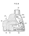
- Figs. 8 and 9 are front views of water purifier according to different embodiments of the present invention;
- Fig. 10 is a vertical sectional view of a water purifier according to one embodiment of the present invention;
- Fig. 11 is a right side view of the water purifier;
- Figs. 12 and 13 are sectional views showing the principal part of a water faucet; and
- Figs. 14, 15 and 16 are perspective views of a
valve body 80. - Figs. 1 and 2 are sectional and side views of one embodiment of a water faucet. 2 is an inlet port communicated with an
outlet port 4 through adischarge passageway 3. A male thread is formed on the outer periphery of theinlet port 2. An O-ring 5 is also fit around theinlet port 2. Thewater faucet 1 has anintegral control chamber 6. Included in thecontrol chamber 6 is abase plate 8 on which a control circuit (not shown) and a LED (light emitting diode) 7 are placed. - A
sensor 9 is exposed to thedischarge passageway 3 to detect the volume, temperature, pressure, pH (hydrogen ion concentration) or hardness (e.g. calcium carbonate) of water in thedischarge passageway 3. As an alternative, thesensor 9 may be disposed behind (or so as not to extend through) the pipe wall of thepassageway 3. In such a case, the temperature of water in thepassageway 3 can be detected by sensing heat transmitted through the pipe wall. - The
sensor 9 is connected to thebase plate 8 through alead wire 10. Twooptical fibers LED 7. Theother ends 11A and 12A of theoptical fibers outlet port 4. 13 is an electric cell connected to thebase plate 8 through alead wire 14. - With the
water faucet 1 thus constructed,
when water temperature detected by the temperature sensor exceeds a predetermined temperature;
when the rate of flow of water detected by the flow sensor exceeds a predetermined rate;
when water pressure exceeds a predetermined pressure;
when pH is deviated from a predetermined range (for example, between 6 and 8); or
when water hardness exceeds a predetermined level, -
LED 7 is turned on to emit color light to water discharged from theoutlet port 4. As a result, it can be observed that: the temperature of outlet water exceeds a predetermined temperature; the rate of flow of output water exceeds a predetermined rate; water pressure exceeds a predetermined pressure; ph is deviated from a predetermined range; or hardness exceeds a predetermined level. A user always visually recognize the temperature, the volume, the pressure, pH and hardness of water whenever thewater faucet 1 is used. - In the present invention, a water pressure sensor can be used as the
sensor 9, and LED is turned on when output water pressure is above a predetermined level. In this way, it can visually be recognized that the pressure of the outlet water from thewater faucet 1 is high, and splashing is easily obtainable. - Fig. 3 is a sectional view of a
water faucet 1A according to another embodiment of the present invention. Theend 11A of theoptical fiber 11 is oriented toward thepassageway 3 to emit light to theoutlet port 4. 15 is a transparent seal. Now that light is emitted to the output water, this embodiment is also operated in the same manner and provides the same advantages as stated earlier. Preferably, light is emitted from theend 11A of theoptical fiber 11 directly to theoutlet port 4. Alternatively, light may reaches theoutlet port 4 while being normally or randomly reflected from the inner surface of thepassageway 3. - Fig. 4 is a vertical sectional view of a combined hot and
cold water faucet 1B. Theend 11A of theoptical fiber 11 is so oriented as to emit light to theoutlet port 4. - Hot water flows into a mixing
valve 15 through an inlet port 2A (not shown). Cold water flows into the mixingvalve 15 through aninlet port 2B. The mixingvalve 15 is operable to mix hot and cold water in a manner to produce a mixture of a predetermined temperature. The mixture then flows into a mixingchamber 16 and out of theoutlet port 4 through anoutlet opening 17 and aconduit 18. The other like reference numerals in Fig. 4 designate like elements in Fig. 1. Now that light is emitted to the output water, this embodiment is also operable in the same manner and provides the same advantages as stated earlier. - Fig. 5 is a vertical sectional view of an apparatus for discharging water (water purifier) according to one embodiment of the present invention (taken along the line V-V of Fig. 7). Fig. 6 is a side view, and Fig. 7 is a front view.
- A
water purifier 21 includes aninlet port 22 at its upper portion and anoutlet port 23 at its lower portion. Theinlet port 22 and theoutlet port 23 are communicated with one another through apassageway 24. Achangeover valve 25 is arranged in thepassageway 24 to selectively communicate theinlet port 22 with theoutlet port 23 and abranch passage 26. Thebranch passage 26 is coupled to aninlet 27A of apurifier cartridge 27. Thepurifier cartridge 27 has anoutlet 27B communicated with thepassageway 24 through apurified water passage 28. - The
changeover valve 25 has an operatingshaft 25A extending externally of thewater purifier 21. Ahandle 25B is secured to one end of the operatingshaft 25A. An arm extends radially from the operatingshaft 25A. When thehandle 25B is operated, thearm 25C is brought into engagement with alimit switch 29. Acontrol chamber 30 is defined at the rear of thewater purifier 21 and includes acircuit board 32 on which a control circuit (not shown) andLED 31 are placed. 33 is an electric cell adapted to supply electric power to thecircuit board 33. Theelectric cell 33 and thelimit swicth 29 are connected to thecircuit board 32 throughlead wires - Two
optical fibers LED 31. The other ends B of theoptical fibers outlet port 23 so as to direct light fromLED 31 to water flowing out of theoutlet port 23. - With the
water purifier 21 thus constructed, when thehandle 25B is turned to a tap water position, thechangeover valve 25 is operable to provide a direct communication between theinlet port 22 and theoutlet port 23. Tap water flows from theinlet port 22 toward theoutlet port 23 through thepassageway 24, not through thepurifier cartridge 27. The tap water is then discharged from theoutlet port 23. In this case,LED 31 is rendered inoperative, and no light is directed to tap water flowing out of theoutlet port 23. - When the
handle 25B is turned to a purified water position, theinlet port 22 is brought into communication only with thebranch passage 26. Tap water flows from theinlet port 22 into the purifiedwater cartridge 27. The tap water is, then, purified by a purifying agent such as an activated carbon filled in the purifiedwater cartridge 27. This purified water is returned to thepassageway 27 through the purifiedwater passage 28 and then, discharged from theoutlet port 23. When thehandle 25B is turned to its purified water position, thearm 25C comes into contact with thelimit switch 29. A signal is then send to the circuit on thecircuit board 32. A control circuit on thecircuit board 32 is rendered operative to turn onLED 31 in response to the input signal. Light is emitted from the end A ofLED 31 to theoptical fibers optical fibers outlet port 23. -
LED 31 emits color light. Accordingly, the output purified water is observed as if it is colored. A user almost always views water discharged from theoutlet port 23 when thewater purifier 21 is in use. The user can visually recognize whether the output water is purified by looking at the water to which color light is emitted. - Fig. 8 illustrates a water purifier 21' according to another embodiment of the present invention. The end B of the
optical fiber 37 is oriented toward thepassageway 24 so as to emit light to theoutlet port 23. 38 is a transparent seal. Now that light is emitted to theoutlet port 23, this embodiment is also operated in the same manner and provides the same advantages as stated earlier. - Preferably, light is emitted from the end B of the
optical fiber 37 directly to theoutlet port 23. Alternatively, light may reach theoutlet port 23 while being normally or randomly reflected from the inner surface of thepassageway 24. - Fig. 9 is a front view of a water purifier 21'' according to a still another embodiment of the present invention. In this embodiment, a
water quality sensor 40 is arranged in the purifiedwater passage 28 to detect the quality of purified water. Thissensor 40 is operable to send a signal to the circuit board (not shown in Fig. 5). In this embodiment, LED (not shown) is rendered operative to emit light of different color to water discharged from theoutlet port 23 when the quality of the water as purified in the purifiedwater cartridge 27 is below a predetermined level. Thus, the user can recognize whether the service life of the purifying agent in the purifiedwater cartridge 27 is over. - The
water quality sensor 40 may be in the form of an electric conductance meter or chlorine sensor. - In the embodiment of the present invention, as shown in Fig. 9, a flowmeter (not shown) may be provided in place of the water purified
sensor 40. In thecircuit board 32, the flow of purified water flowing through the purifiedwater passage 28 is integrated. Light of different color is then emitted to the water discharged from theoutlet port 23 when the integrated flow is above a predetermined level. In this way, the user is able to know the time to replace the existing purifying agent. - Fig. 10 is a vertical sectional view of a
water faucet 50 for use in the water purifier according to one embodiment of the present invention. Fig. 11 is a right side view, partly in section, of the water faucet. Figs. 12 and 13 are sectional views of a valve casing taken along the lines of XII-XII and XIII-XIII of Fig. 10. Figs. 14, 15 and 16 are perspective views of avalve element 80. - The
water faucet 50 includes afaucet casing 52 in which avalve body 54 is received. Thefaucet casing 52 includes anupper casing 56 and alower casing 58. Theupper casing 56 is flat as viewed in plan. Anopening 62 is formed in one side of the top of the upper casing to mount apurified water cartridge 60. Formed in the opposite side of the top of the upper casing is anopening 66 through which aninlet port 64 of therotary valve 54 extends outwardly of thecasing 52. - The
lower casing 58 is also flat as viewed in plan and has anopening 74 through which anoutlet port 72 of thevalve body 54 extends outwardly of thefaucet casing 52. - A
passage 60 is defined in the bottom of thelower casing 58 so that water as purified in the purifiedwater cartridge 60 flows into theoutlet port 72. - A
valve element 80 is inserted into thevalve body 54. Thevalve body 54 has an integral purified watercartridge connecting section 82. Water flows from thevalve element 80 into the purified watercartridge connecting section 82 through a connectingpassage 84. The purified watercartridge connecting section 82 includes anouter passage 86 and aninner passage 88. - A
purified water outlet 60A extends centrally from the bottom of the purifiedwater cartridge 60. Aunpurified water inlet 60B is defined coaxially around the purifiedwater outlet 60A. The purifiedwater cartridge 60 includes afiltering element 60C such as an activated carbon. - Water flows from the
outer passage 86 into the purifiedwater cartridge 60 through theunpurified water inlet 60B and is, then, purified by means of theelement 60C. The water thus purified flows from the purifiedwater outlet 60A to theinner passage 88. - The
valve element 80 is substantially cylindrical and includes a firstball holding recess 92 and a secondball holding recess 94. - As clearly shown in Figs. 14, 15 and 16, the
ball holding recess 92 extends laterally of thevalve element 80. Thisball holding recess 92 is communicated with anend opening 96 of thevalve element 80 through a slot orpassage 98. Aball 100 is received in theball holding recess 82. - The
ball holding recess 94 extends laterally of thevalve element 80. Theball holding recess 94 extends at right angles to theball holding recess 92. Aball 102 is received in theball holding recess 94. - A
partition 97 extends between theball holding recess 92 and thepassage 98 and has a notch 97A. Apartition 99 extends between theball holding recess 92 and theball holding recess 94 and has anotch 99A. The slot orpassage 98, theball holding recess 92 and theball holding recess 94 are mutually communicated with one another through thesenotches 97A and 99A. Formed behind theball holding recesses arcuate recesses - The
valve body 54 includes aninlet port 104 at its top, andoutlet ports - A
tubular member 110 extends downwardly from thevalve body 54 and forms anoutlet port 106. Anopening 112 is defined in thetubular member 110 to provide a communication between thepassage 70 and the interior of thetubular member 110. - The
reference numeral 114 denotes a cap. Thecap 114 has acentral outlet 116 in communication with theoutlet port 106. -
Shower outlets 118 are defined in the periphery of thecap 114 and communicated with theoutlet port 108. - The
shower outlets 108 are also communicated with thepassage 70. - An operating
shaft 124 extends from one end of thevalve element 80 opposite to the end in which theend opening 96 is defined. Ahandle 126 is fit over the operatingshaft 124. The operatingshaft 124 extends through thefaucet casing 52. - The
reference numeral 128 denotes a bearing for the operatingshaft 124. Thebearing 128 has a radial bore 132 into which aswitch 134 extends. Theswitch 134 includes a spring adapted to urge aprotrusion 136 outwardly. Theprotrusion 136 is in contact with the inner surface of thelower casing 58. - A
recess 140 is formed in the outer periphery of the operatingshaft 124. When the head of theswitch 134 extends into therecess 140, theswitch 124 is extended under the influence of the internal spring so as to open the contact of theswitch 124. On the other hand, when the head of theswitch 134 comes into contact with the outer periphery of the operating shaft other than therecess 140, theswitch 134 is shortened to close the contact of the switch. - Formed behind the
casing 52 is acircuit chamber 142 in which anelectric cell 144, acircuit board 146 and LED 150 are situated. Anoptical fiber 152 is positioned to direct light from LED 150 to near theoutlet 118. 148 is a lead wire by which theswitch 134 and theboard 146 are connected together. - The water purifier includes the
water faucet 50 and the purifiedwater cartridge 60. With this arrangement, water flows from theinlet port 104 into the valve element whereby the water separately flows. - As shown in Figs. 10 and 16, if the
valve element 80 is positioned such that the firstball holding recess 92 is oriented toward theinlet port 104 and theoutlet port 108, and the secondball holding recess 94 is oriented only toward theinlet port 104, then theend opening 96 is disconnected from the connectingpassage 84, and theshower outlets 108 are closed by theball 100. Water, as introduced through theinlet port 104, flows around thevalve element 80, through therecess 94A and the tapwater outlet port 106, and out of thecentral outlet 116. - If the
valve element 80 is rotated by 90° in the direction of the arrow R in Fig. 16 from the position shown in Figs. 10 and 16 to the position shown in Fig. 15, then theoutlet port 108 is opened. Instead, the tapwater outlet port 106 is closed by theball 102. The connectingpassage 84 remains closed. As a result, water, introduced through theinlet port 104, flows around thevalve element 80, through theoutlet port 108 and out of theshower outlets 118. - If the
valve element 80 is rotated by 180 ° from the postion shown in Fig. 16 to the position shown in Fig. 14, then theball holding recess 92 is oriented toward theoutlet port 108. This causes theball 100 to close theoutlet port 108. Theball holding recess 108 is also oriented toward the tapwater outlet port 106. This causes theball 102 to close the tapwater outlet port 106. Theend opening 96 is instead brought into communication with the connectingpassage 84. As a result, water from theinlet port 104, through thepassage 98, theend opening 96, the connectingpassage 84, theouter passage 86, thefaucet casing 60, theinner passage 88 and thepassage 70 in that order, and out both of thecentral outlet 116 and theshower outlets 118. - When the valve element is rotated to the position shown in Fig. 14, the outer periphery of the operating
shaft 124, except for the recess, comes into contact with theswitch 134. This results in a decrease in the length of theswitch 134. The switch is then on so that LED 150 may emit light. The light is emitted from LED 150 through theoptical fiber 152 to the output water. Now that color light is directed to the output water, it is easily seen whether the output water has been purified in the purifiedwater cartridge 60. - As discussed above, according to the present invention, a user can safely visually recognize the temperature, volume, pressure, concentration (for example, pH, and hardness), and kinds of water (for example, purified water and tap water). In the present invention, it may, for example, emit light of different colors to the output water in response to water temperature. Light may be used to illuminate rooms. Additionally, light may be emitted when the temperature or volume of water is increased. Light colors or intervals of emission may be selected to prevent burning of the user or to save on water.
Claims (15)
- An apparatus for discharging water including a water passageway, said apparatus comprising sensor means for sensing characteristics of water flowing through said water passageway, and light emitting means for emitting light to said water passageway or a region downstream of said water passageway in response to the characteristics as sensed.
- An apparatus for discharging water as claimed in claim 1, wherein said characteristics includes one or more of the following: water temperature, water flow, water pressure and water concentration.
- An apparatus for discharging water as claimed in claim 2, wherein said water concentration is pH and/or hardness.
- An apparatus for discharging water including an outlet port, a plurality of feed water passages connected to said outlet port, and passage selection means for selectively communicating said outlet port with either one of said plurality of feed water passages, the improvement comprising sensor means for sensing which one of said plurality of feed water passages are selected by said passage selection means, and light emitting means for emitting light to said feed water passages or a region through which water flows from said outlet port in response to the sensing by said sensor means.
- An apparatus for discharging water as claimed in claim 4, further comprising a filtering element disposed in either one of said feed water passages.
- An apparatus for discharging water including a filtering element, said apparatus comprising sensor means disposed downstream of said filtering element for sensing the quality of water, and light emitting means for emitting light to a passage in said apparatus or a region through which said water flows from an outlet port in response to the sensing by said sensor means.
- An apparatus for discharging water including a filtering element, said apparatus comprising sensor means for sensing integrated flow of water flowing through said filtering element, and light emitting means for emitting light to a passage in said apparatus or a region through which said water flows from an outlet port in response to the integrated flow as sensed.
- An apparatus for discharging water as claimed in claim 1, wherein said light emitting means comprises a light emitting device and an optical fiber for guiding light from said light emitting device.
- An apparatus for discharging water as claimed in claim 4, wherein said light emitting means comprises a light emitting device and an optical fiber for guiding light from said light emitting device.
- An apparatus for discharging water as claimed in claim 6, wherein said light emitting means comprises a light emitting device and an optical fiber for guiding light from said light emitting device.
- An apparatus for discharging water as claimed in claim 7, wherein said light emitting means comprises a light emitting device and an optical fiber for guiding light from said light emitting device.
- An apparatus for discharging water as claimed in claim 8, wherein said light emitting device is a light emitting diode.
- An apparatus for discharging water as claimed in claim 9, wherein said light emitting device is a light emitting diode.
- An apparatus for discharging water as claimed in claim 10, wherein said light emitting device is a light emitting diode.
- An apparatus for discharging water as claimed in claim 11, wherein said light emitting device is a light emitting diode.
Applications Claiming Priority (4)
| Application Number | Priority Date | Filing Date | Title |
|---|---|---|---|
| JP25448289 | 1989-09-29 | ||
| JP25448189 | 1989-09-29 | ||
| JP254481/89 | 1989-09-29 | ||
| JP254482/89 | 1989-09-29 |
Publications (2)
| Publication Number | Publication Date |
|---|---|
| EP0446365A1 true EP0446365A1 (en) | 1991-09-18 |
| EP0446365A4 EP0446365A4 (en) | 1992-07-08 |
Family
ID=26541698
Family Applications (1)
| Application Number | Title | Priority Date | Filing Date |
|---|---|---|---|
| EP19900913867 Withdrawn EP0446365A4 (en) | 1989-09-29 | 1990-09-21 | Water discharging apparatus |
Country Status (5)
| Country | Link |
|---|---|
| US (1) | US5171429A (en) |
| EP (1) | EP0446365A4 (en) |
| JP (1) | JP2949818B2 (en) |
| KR (1) | KR920701586A (en) |
| WO (1) | WO1991005114A1 (en) |
Cited By (20)
| Publication number | Priority date | Publication date | Assignee | Title |
|---|---|---|---|---|
| WO1995029300A1 (en) * | 1994-04-27 | 1995-11-02 | Lin Li | Apparatus and method for introducing electromagnetic waves into water |
| WO1998004785A1 (en) * | 1996-07-31 | 1998-02-05 | Arichell Technologies, Inc. | Object-sensor-based flow-control system employing fiber-optic signal transmission |
| WO1998028496A1 (en) * | 1996-12-24 | 1998-07-02 | Gunter Veigel | Water draining fittings |
| EP0896176A3 (en) * | 1997-08-08 | 2000-11-08 | Emhart Inc. | Faucet spout assembly |
| WO2001022096A1 (en) | 1999-09-23 | 2001-03-29 | Enviro Developpement | Device for visual display of the flow rate and the temperature of a fluid |
| EP0961067A3 (en) * | 1998-05-26 | 2001-04-25 | Ideal Standard S.R.L. | Tap for delivering water at adjustable temperature, for sanitary appliances |
| GB2393389A (en) * | 2002-08-29 | 2004-03-31 | Cda Group Ltd | Water dispensing device |
| EP1464889A2 (en) * | 2003-03-27 | 2004-10-06 | Calipso Srl | Device to illuminate water jets in a sanitary appliance such as a bathtub, a shower cubicle or suchlike |
| WO2005100852A1 (en) * | 2004-04-13 | 2005-10-27 | Saf Armaturen Gmbh | Process and device for generating coloured liquid streams in hot-water fittings |
| EP1590589A1 (en) * | 2003-01-16 | 2005-11-02 | Lee, Chul Jae | Light emitting apparatus in tap water responding to water temperature |
| EP1705297A1 (en) | 2005-03-11 | 2006-09-27 | Kwc Ag | Sanitary fixture with light-guiding discharge tube |
| DE202008003087U1 (en) | 2008-03-04 | 2008-08-21 | Butzke, Wolfgang | Device for producing the same color effects when combining liquid streams and translucent catch basins |
| US7628512B2 (en) | 2005-10-26 | 2009-12-08 | Pentair Water Pool And Spa, Inc. | LED pool and spa light |
| US7794095B2 (en) | 2005-03-11 | 2010-09-14 | Kwc Ag | Sanitary fitting with a lightguide outflow pipe |
| DE102004045428B4 (en) * | 2004-09-18 | 2013-01-10 | Hansa Metallwerke Ag | Sanitary mixing fitting with an electronic display device |
| DE202017106899U1 (en) | 2017-11-14 | 2017-11-20 | Wenko-Wenselaar Gmbh & Co. Kg | Shower rod with integrated light source |
| IT201700036357A1 (en) * | 2017-04-03 | 2018-10-03 | Inoxcommercio S R L | SWIVEL COCK 360 ° SAVE-DROP FOR FOOD USE. |
| DE102017126729A1 (en) | 2017-11-14 | 2019-05-16 | Wenko-Wenselaar Gmbh & Co. Kg | Shower rod with integrated light source |
| WO2022078551A1 (en) | 2020-10-12 | 2022-04-21 | Wenko-Wenselaar Gmbh & Co. Kg | Function carrier for sanitary spaces and having an integrated light source |
| DE102020126651A1 (en) | 2020-10-12 | 2022-05-05 | Wenko-Wenselaar GmbH & Co. Kommanditgesellschaft | FUNCTIONAL CARRIERS FOR SANITARY ROOMS WITH INTEGRATED LAMPS |
Families Citing this family (77)
| Publication number | Priority date | Publication date | Assignee | Title |
|---|---|---|---|---|
| US5491617A (en) * | 1993-05-12 | 1996-02-13 | Currie; Joseph E. | Illuminated fluid tap |
| US5535779A (en) * | 1994-06-30 | 1996-07-16 | Huang; Lung-Shen | Water outlet control device |
| US5823229A (en) * | 1996-12-06 | 1998-10-20 | Moen Incorporated | Faucet having multiple water discharges |
| US5858215A (en) * | 1996-12-06 | 1999-01-12 | Moen Incorporated | Water filter containing faucet and display therefor |
| US6093313A (en) * | 1996-12-06 | 2000-07-25 | Moen Incorporated | Multiple discharge water faucet with self-contained filter |
| US6774584B2 (en) | 1997-08-26 | 2004-08-10 | Color Kinetics, Incorporated | Methods and apparatus for sensor responsive illumination of liquids |
| US6781329B2 (en) | 1997-08-26 | 2004-08-24 | Color Kinetics Incorporated | Methods and apparatus for illumination of liquids |
| US7385359B2 (en) | 1997-08-26 | 2008-06-10 | Philips Solid-State Lighting Solutions, Inc. | Information systems |
| US6869204B2 (en) | 1997-08-26 | 2005-03-22 | Color Kinetics Incorporated | Light fixtures for illumination of liquids |
| US7187141B2 (en) * | 1997-08-26 | 2007-03-06 | Color Kinetics Incorporated | Methods and apparatus for illumination of liquids |
| US7482764B2 (en) | 1997-08-26 | 2009-01-27 | Philips Solid-State Lighting Solutions, Inc. | Light sources for illumination of liquids |
| US6132056A (en) * | 1998-06-29 | 2000-10-17 | Ruthenberg; Douglas | Apparatus for creating an illuminated waterfall |
| US6196471B1 (en) | 1999-11-30 | 2001-03-06 | Douglas Ruthenberg | Apparatus for creating a multi-colored illuminated waterfall or water fountain |
| US7642730B2 (en) | 2000-04-24 | 2010-01-05 | Philips Solid-State Lighting Solutions, Inc. | Methods and apparatus for conveying information via color of light |
| US6801003B2 (en) | 2001-03-13 | 2004-10-05 | Color Kinetics, Incorporated | Systems and methods for synchronizing lighting effects |
| US6637676B2 (en) * | 2001-04-27 | 2003-10-28 | Interbath, Inc. | Illuminated showerhead |
| US6805458B2 (en) | 2002-08-15 | 2004-10-19 | Gelcore Llc | Night light for plumbing fixtures |
| DE10238171A1 (en) * | 2002-08-21 | 2004-03-04 | Wörner, Helmut | LED water jet |
| US7114666B2 (en) | 2002-12-10 | 2006-10-03 | Water Pik, Inc. | Dual massage shower head |
| DE10347615B3 (en) * | 2003-10-09 | 2005-05-25 | Paul Kessener | Fluid lighting device with color change |
| US7740186B2 (en) | 2004-09-01 | 2010-06-22 | Water Pik, Inc. | Drenching shower head |
| DE102004053978A1 (en) * | 2004-11-09 | 2006-05-18 | Interservice Water Technology Vertriebs Gmbh | Water processing apparatus, especially filter for obtaining drinkable water, including thermal valve preventing water above a predetermined threshold temperature from flowing into the apparatus |
| DE102005010349B4 (en) * | 2005-03-07 | 2009-10-15 | Hansa Metallwerke Ag | plumbing fixture |
| US20060250795A1 (en) * | 2005-05-03 | 2006-11-09 | Michael Langone | Means and device for providing automatically activated illumination of novelty containers |
| US20060250784A1 (en) * | 2005-05-03 | 2006-11-09 | Michael Langone | Apparatus for providing illumination of fluid streams |
| US20060274527A1 (en) * | 2005-06-04 | 2006-12-07 | Michael Langone | Apparatus for providing illuminated images associated with containers |
| JP2007023689A (en) * | 2005-07-20 | 2007-02-01 | Inax Corp | Toilet |
| JP4716814B2 (en) * | 2005-08-09 | 2011-07-06 | 株式会社Inax | Western style flush toilet |
| JP2007125194A (en) * | 2005-11-04 | 2007-05-24 | Matsushita Electric Works Ltd | Luminous washstand |
| WO2007124455A2 (en) | 2006-04-20 | 2007-11-01 | Water Pik, Inc. | Converging spray showerhead |
| CN101466977A (en) * | 2006-06-09 | 2009-06-24 | 皇家飞利浦电子股份有限公司 | Control of bath water color with light |
| EP1870526B1 (en) * | 2006-06-21 | 2016-04-06 | Franke Water Systems AG | Sanitary fixture |
| US7392552B2 (en) * | 2006-09-01 | 2008-07-01 | Su-Lan Wu | Light-effect module for faucet |
| US8020787B2 (en) | 2006-11-29 | 2011-09-20 | Water Pik, Inc. | Showerhead system |
| US7789326B2 (en) | 2006-12-29 | 2010-09-07 | Water Pik, Inc. | Handheld showerhead with mode control and method of selecting a handheld showerhead mode |
| US7770822B2 (en) | 2006-12-28 | 2010-08-10 | Water Pik, Inc. | Hand shower with an extendable handle |
| US8366024B2 (en) | 2006-12-28 | 2013-02-05 | Water Pik, Inc. | Low speed pulsating showerhead |
| US8794543B2 (en) | 2006-12-28 | 2014-08-05 | Water Pik, Inc. | Low-speed pulsating showerhead |
| US8371618B2 (en) | 2007-05-04 | 2013-02-12 | Water Pik, Inc. | Hidden pivot attachment for showers and method of making same |
| JP5084436B2 (en) * | 2007-10-18 | 2012-11-28 | 株式会社Lixil | Water discharge device |
| JP5234496B2 (en) * | 2008-03-27 | 2013-07-10 | Toto株式会社 | Faucet device |
| JP2009235803A (en) * | 2008-03-27 | 2009-10-15 | Toto Ltd | Faucet device |
| USD624156S1 (en) | 2008-04-30 | 2010-09-21 | Water Pik, Inc. | Pivot ball attachment |
| US8348181B2 (en) | 2008-09-15 | 2013-01-08 | Water Pik, Inc. | Shower assembly with radial mode changer |
| USD616061S1 (en) | 2008-09-29 | 2010-05-18 | Water Pik, Inc. | Showerhead assembly |
| USD625776S1 (en) | 2009-10-05 | 2010-10-19 | Water Pik, Inc. | Showerhead |
| US8616470B2 (en) | 2010-08-25 | 2013-12-31 | Water Pik, Inc. | Mode control valve in showerhead connector |
| US9074357B2 (en) | 2011-04-25 | 2015-07-07 | Delta Faucet Company | Mounting bracket for electronic kitchen faucet |
| US8622247B2 (en) * | 2011-07-13 | 2014-01-07 | Steve Zuloff | Light up liquid projection device and method thereof |
| US9057184B2 (en) | 2011-10-19 | 2015-06-16 | Delta Faucet Company | Insulator base for electronic faucet |
| USD678467S1 (en) | 2012-01-27 | 2013-03-19 | Water Pik, Inc. | Ring-shaped handheld showerhead |
| USD678463S1 (en) | 2012-01-27 | 2013-03-19 | Water Pik, Inc. | Ring-shaped wall mount showerhead |
| US9068327B2 (en) * | 2012-05-19 | 2015-06-30 | Oskar L. Granstrand | Flow meter for the measuring of fluid volumes originating from a faucet |
| CA2820623C (en) | 2012-06-22 | 2017-10-03 | Water Pik, Inc. | Bracket for showerhead with integral flow control |
| US9333698B2 (en) | 2013-03-15 | 2016-05-10 | Delta Faucet Company | Faucet base ring |
| KR101771830B1 (en) * | 2013-05-20 | 2017-08-25 | 오므론 가부시키가이샤 | Washing position confirmation device, fluid delivery position confirmation device, washing position confirmation system, and fluid delivery position confirmation method |
| EP3513879A1 (en) | 2013-06-13 | 2019-07-24 | Water Pik, Inc. | Showerhead with turbine driven shutter |
| USD744612S1 (en) | 2014-06-13 | 2015-12-01 | Water Pik, Inc. | Handheld showerhead |
| USD744066S1 (en) | 2014-06-13 | 2015-11-24 | Water Pik, Inc. | Wall mount showerhead |
| USD744614S1 (en) | 2014-06-13 | 2015-12-01 | Water Pik, Inc. | Wall mount showerhead |
| USD745111S1 (en) | 2014-06-13 | 2015-12-08 | Water Pik, Inc. | Wall mount showerhead |
| USD744611S1 (en) | 2014-06-13 | 2015-12-01 | Water Pik, Inc. | Handheld showerhead |
| USD744064S1 (en) | 2014-06-13 | 2015-11-24 | Water Pik, Inc. | Handheld showerhead |
| USD744065S1 (en) | 2014-06-13 | 2015-11-24 | Water Pik, Inc. | Handheld showerhead |
| US20160208948A1 (en) * | 2015-01-19 | 2016-07-21 | Moen Incorporated | Electronic plumbing fixture fitting with electronic valve having operation modes |
| NL1041393B1 (en) | 2015-07-07 | 2017-01-30 | Kessener B V | Method and device providing a liquid display. |
| CN105198023B (en) * | 2015-10-28 | 2018-07-20 | 小米科技有限责任公司 | Control the method, apparatus and water purifier of water purifier discharge water |
| CA3013213C (en) | 2016-02-01 | 2021-04-20 | Water Pik, Inc. | Handheld pet spray wand |
| USD803981S1 (en) | 2016-02-01 | 2017-11-28 | Water Pik, Inc. | Handheld spray nozzle |
| US10265710B2 (en) | 2016-04-15 | 2019-04-23 | Water Pik, Inc. | Showerhead with dual oscillating massage |
| USD970684S1 (en) | 2016-04-15 | 2022-11-22 | Water Pik, Inc. | Showerhead |
| US10441960B2 (en) | 2016-09-08 | 2019-10-15 | Water Pik, Inc. | Pause assembly for showerheads |
| USD843549S1 (en) | 2017-07-19 | 2019-03-19 | Water Pik, Inc. | Handheld spray nozzle |
| USD872227S1 (en) | 2018-04-20 | 2020-01-07 | Water Pik, Inc. | Handheld spray device |
| JP7240873B2 (en) * | 2018-12-26 | 2023-03-16 | 三菱ケミカル・クリンスイ株式会社 | hydrant |
| DE102019103605A1 (en) * | 2019-02-13 | 2020-08-13 | Grohe Ag | Measurement of the CO2 content and the filter performance in water modification units |
| US11602032B2 (en) | 2019-12-20 | 2023-03-07 | Kohler Co. | Systems and methods for lighted showering |
Citations (3)
| Publication number | Priority date | Publication date | Assignee | Title |
|---|---|---|---|---|
| DE3135861A1 (en) * | 1981-09-10 | 1983-03-24 | Friedrich Grohe Armaturenfabrik Gmbh & Co, 5870 Hemer | Discharge fitting for water |
| DE8802245U1 (en) * | 1988-02-22 | 1988-05-11 | Roedder, Oliver, 4710 Luedinghausen, De | |
| WO1989009312A1 (en) * | 1988-03-22 | 1989-10-05 | Ryemetal Forgings (Vic) Pty. Ltd. | Electronic tapware |
Family Cites Families (12)
| Publication number | Priority date | Publication date | Assignee | Title |
|---|---|---|---|---|
| JPS4725951A (en) * | 1971-03-25 | 1972-10-23 | ||
| JPS5986291U (en) * | 1982-12-03 | 1984-06-11 | オルガノ株式会社 | Faucet with water quality indicator |
| JPS6041593Y2 (en) * | 1982-12-27 | 1985-12-18 | 清川株式会社 | Flashing device mounting mechanism |
| JPS62122618A (en) * | 1985-11-25 | 1987-06-03 | 松下電器産業株式会社 | Bathtub |
| JPS6358373A (en) * | 1986-08-29 | 1988-03-14 | Canon Inc | Information recorder |
| JPH073891B2 (en) * | 1987-06-09 | 1995-01-18 | 株式会社東芝 | Light emitting element array |
| JPS6419667U (en) * | 1987-07-23 | 1989-01-31 | ||
| JPH01165936A (en) * | 1987-12-22 | 1989-06-29 | Meidensha Corp | Detecting apparatus of concentration of suspended substance |
| US4851818A (en) * | 1988-04-01 | 1989-07-25 | Eastman Kodak Company | Electronic controller for a water purifying unit |
| US4849098A (en) * | 1988-04-07 | 1989-07-18 | Anthony Wilcock | Continuous water quality monitor |
| US4933080A (en) * | 1989-01-13 | 1990-06-12 | Associated Mills Inc. | Housing with replaceable filter cartridge for use with shower head |
| US5114570A (en) * | 1989-08-14 | 1992-05-19 | Teledyne Industries Inc. | Water filter cartridge |
-
1990
- 1990-09-21 WO PCT/JP1990/001212 patent/WO1991005114A1/en not_active Application Discontinuation
- 1990-09-21 KR KR1019910700531A patent/KR920701586A/en not_active Application Discontinuation
- 1990-09-21 EP EP19900913867 patent/EP0446365A4/en not_active Withdrawn
- 1990-09-21 US US07/700,160 patent/US5171429A/en not_active Expired - Fee Related
- 1990-09-25 JP JP25481290A patent/JP2949818B2/en not_active Expired - Lifetime
Patent Citations (3)
| Publication number | Priority date | Publication date | Assignee | Title |
|---|---|---|---|---|
| DE3135861A1 (en) * | 1981-09-10 | 1983-03-24 | Friedrich Grohe Armaturenfabrik Gmbh & Co, 5870 Hemer | Discharge fitting for water |
| DE8802245U1 (en) * | 1988-02-22 | 1988-05-11 | Roedder, Oliver, 4710 Luedinghausen, De | |
| WO1989009312A1 (en) * | 1988-03-22 | 1989-10-05 | Ryemetal Forgings (Vic) Pty. Ltd. | Electronic tapware |
Non-Patent Citations (1)
| Title |
|---|
| See also references of WO9105114A1 * |
Cited By (31)
| Publication number | Priority date | Publication date | Assignee | Title |
|---|---|---|---|---|
| WO1995029300A1 (en) * | 1994-04-27 | 1995-11-02 | Lin Li | Apparatus and method for introducing electromagnetic waves into water |
| GB2288974B (en) * | 1994-04-27 | 1998-09-30 | Lin Li | Sanitary installations with illuminated water |
| WO1998004785A1 (en) * | 1996-07-31 | 1998-02-05 | Arichell Technologies, Inc. | Object-sensor-based flow-control system employing fiber-optic signal transmission |
| US5984262A (en) * | 1996-07-31 | 1999-11-16 | Arichell Technologies, Inc. | Object-sensor-based flow-control system employing fiber-optic signal transmission |
| WO1998028496A1 (en) * | 1996-12-24 | 1998-07-02 | Gunter Veigel | Water draining fittings |
| US6126290A (en) * | 1996-12-24 | 2000-10-03 | Veigel; Gunter | Water draining fixture with light guide illumination means |
| EP0896176A3 (en) * | 1997-08-08 | 2000-11-08 | Emhart Inc. | Faucet spout assembly |
| US6179130B1 (en) | 1997-08-08 | 2001-01-30 | Emhart Inc. | Faucet spout assembly |
| EP0961067A3 (en) * | 1998-05-26 | 2001-04-25 | Ideal Standard S.R.L. | Tap for delivering water at adjustable temperature, for sanitary appliances |
| WO2001022096A1 (en) | 1999-09-23 | 2001-03-29 | Enviro Developpement | Device for visual display of the flow rate and the temperature of a fluid |
| FR2799834A1 (en) * | 1999-09-23 | 2001-04-20 | Enviro Dev | DEVICE FOR VISUALIZING THE FLOW AND TEMPERATURE OF A FLUID |
| US6494107B1 (en) | 1999-09-23 | 2002-12-17 | Enviro Developpement | Device for visual display of the flow rate and the temperature of a fluid |
| GB2393389A (en) * | 2002-08-29 | 2004-03-31 | Cda Group Ltd | Water dispensing device |
| US7553076B2 (en) | 2003-01-16 | 2009-06-30 | Seung Hong Yoon | Light emitting apparatus in tap water responding to water temperature |
| EP1590589A1 (en) * | 2003-01-16 | 2005-11-02 | Lee, Chul Jae | Light emitting apparatus in tap water responding to water temperature |
| EP1590589A4 (en) * | 2003-01-16 | 2006-01-18 | Lee Chul Jae | Light emitting apparatus in tap water responding to water temperature |
| EP1464889A3 (en) * | 2003-03-27 | 2005-12-07 | Calipso Srl | Device to illuminate water jets in a sanitary appliance such as a bathtub, a shower cubicle or suchlike |
| EP1464889A2 (en) * | 2003-03-27 | 2004-10-06 | Calipso Srl | Device to illuminate water jets in a sanitary appliance such as a bathtub, a shower cubicle or suchlike |
| WO2005100852A1 (en) * | 2004-04-13 | 2005-10-27 | Saf Armaturen Gmbh | Process and device for generating coloured liquid streams in hot-water fittings |
| DE102004045428B4 (en) * | 2004-09-18 | 2013-01-10 | Hansa Metallwerke Ag | Sanitary mixing fitting with an electronic display device |
| US7794095B2 (en) | 2005-03-11 | 2010-09-14 | Kwc Ag | Sanitary fitting with a lightguide outflow pipe |
| EP1705297A1 (en) | 2005-03-11 | 2006-09-27 | Kwc Ag | Sanitary fixture with light-guiding discharge tube |
| US7467874B2 (en) | 2005-03-11 | 2008-12-23 | Kwc Ag | Sanitary fitting with a lightguide outflow pipe |
| US7628512B2 (en) | 2005-10-26 | 2009-12-08 | Pentair Water Pool And Spa, Inc. | LED pool and spa light |
| DE202008003087U1 (en) | 2008-03-04 | 2008-08-21 | Butzke, Wolfgang | Device for producing the same color effects when combining liquid streams and translucent catch basins |
| IT201700036357A1 (en) * | 2017-04-03 | 2018-10-03 | Inoxcommercio S R L | SWIVEL COCK 360 ° SAVE-DROP FOR FOOD USE. |
| DE202017106899U1 (en) | 2017-11-14 | 2017-11-20 | Wenko-Wenselaar Gmbh & Co. Kg | Shower rod with integrated light source |
| DE102017126729A1 (en) | 2017-11-14 | 2019-05-16 | Wenko-Wenselaar Gmbh & Co. Kg | Shower rod with integrated light source |
| WO2019096352A1 (en) | 2017-11-14 | 2019-05-23 | Wenko-Wenselaar Gmbh & Co. Kg | Shower stall rod having an integrated illuminant |
| WO2022078551A1 (en) | 2020-10-12 | 2022-04-21 | Wenko-Wenselaar Gmbh & Co. Kg | Function carrier for sanitary spaces and having an integrated light source |
| DE102020126651A1 (en) | 2020-10-12 | 2022-05-05 | Wenko-Wenselaar GmbH & Co. Kommanditgesellschaft | FUNCTIONAL CARRIERS FOR SANITARY ROOMS WITH INTEGRATED LAMPS |
Also Published As
| Publication number | Publication date |
|---|---|
| JPH03176519A (en) | 1991-07-31 |
| US5171429A (en) | 1992-12-15 |
| EP0446365A4 (en) | 1992-07-08 |
| KR920701586A (en) | 1992-08-12 |
| JP2949818B2 (en) | 1999-09-20 |
| WO1991005114A1 (en) | 1991-04-18 |
Similar Documents
| Publication | Publication Date | Title |
|---|---|---|
| US5171429A (en) | Apparatus for discharging water with passage selection sensor | |
| US6093313A (en) | Multiple discharge water faucet with self-contained filter | |
| US4744895A (en) | Reverse osmosis water purifier | |
| US6024867A (en) | Counter top water filter with replaceable electronic display monitor | |
| US4682626A (en) | Single-lever water mixer fitting | |
| US6797156B2 (en) | Faucet water treatment | |
| US7810650B2 (en) | Faucet mounted water filter system | |
| US6123837A (en) | Faucet mounted water filter | |
| CN108869792A (en) | Spray head, pull-down spray head and hanging type shower head for tap | |
| JP2007523736A (en) | Disposable long-life cock mounted water filtration device | |
| CN104321491A (en) | Tap and an assembly comprising a boiling water device and such a tap | |
| US4431533A (en) | Filter for liquids, particularly for purifying drinking water | |
| US6214239B1 (en) | Water filter usage monitoring apparatus | |
| JPH044091A (en) | Water purifier | |
| CA2291303C (en) | Multiple discharge water faucet with self-contained filter | |
| US7094334B1 (en) | Water filter having a filter use time indicator | |
| KR200452641Y1 (en) | Water temperature display device | |
| KR101118221B1 (en) | Device for lighting hot water lever of water purifier | |
| JP4584684B2 (en) | Automatic faucet device | |
| CN210484678U (en) | End water inlet sterilizing tap | |
| KR20050063377A (en) | A tap for disinfection and radiation effect | |
| KR20100024287A (en) | Cock valve for water purifier | |
| US11618694B2 (en) | Ultraviolet light-emitting faucet | |
| GB2077470A (en) | Fluid temperature indicator | |
| JP2002346549A (en) | Water cleaner |
Legal Events
| Date | Code | Title | Description |
|---|---|---|---|
| PUAI | Public reference made under article 153(3) epc to a published international application that has entered the european phase |
Free format text: ORIGINAL CODE: 0009012 |
|
| 17P | Request for examination filed |
Effective date: 19910620 |
|
| AK | Designated contracting states |
Kind code of ref document: A1 Designated state(s): CH DE ES FR GB IT LI |
|
| A4 | Supplementary search report drawn up and despatched |
Effective date: 19920521 |
|
| AK | Designated contracting states |
Kind code of ref document: A4 Designated state(s): CH DE ES FR GB IT LI |
|
| 17Q | First examination report despatched |
Effective date: 19930922 |
|
| STAA | Information on the status of an ep patent application or granted ep patent |
Free format text: STATUS: THE APPLICATION IS DEEMED TO BE WITHDRAWN |
|
| 18D | Application deemed to be withdrawn |
Effective date: 19940202 |