EP0450872A1 - Endothermic reaction apparatus - Google Patents
Endothermic reaction apparatus Download PDFInfo
- Publication number
- EP0450872A1 EP0450872A1 EP91302767A EP91302767A EP0450872A1 EP 0450872 A1 EP0450872 A1 EP 0450872A1 EP 91302767 A EP91302767 A EP 91302767A EP 91302767 A EP91302767 A EP 91302767A EP 0450872 A1 EP0450872 A1 EP 0450872A1
- Authority
- EP
- European Patent Office
- Prior art keywords
- tube
- reaction vessel
- reaction
- combustion tube
- combustion
- Prior art date
- Legal status (The legal status is an assumption and is not a legal conclusion. Google has not performed a legal analysis and makes no representation as to the accuracy of the status listed.)
- Granted
Links
Images


Classifications
-
- B—PERFORMING OPERATIONS; TRANSPORTING
- B01—PHYSICAL OR CHEMICAL PROCESSES OR APPARATUS IN GENERAL
- B01J—CHEMICAL OR PHYSICAL PROCESSES, e.g. CATALYSIS OR COLLOID CHEMISTRY; THEIR RELEVANT APPARATUS
- B01J8/00—Chemical or physical processes in general, conducted in the presence of fluids and solid particles; Apparatus for such processes
- B01J8/02—Chemical or physical processes in general, conducted in the presence of fluids and solid particles; Apparatus for such processes with stationary particles, e.g. in fixed beds
- B01J8/04—Chemical or physical processes in general, conducted in the presence of fluids and solid particles; Apparatus for such processes with stationary particles, e.g. in fixed beds the fluid passing successively through two or more beds
- B01J8/0446—Chemical or physical processes in general, conducted in the presence of fluids and solid particles; Apparatus for such processes with stationary particles, e.g. in fixed beds the fluid passing successively through two or more beds the flow within the beds being predominantly vertical
- B01J8/0449—Chemical or physical processes in general, conducted in the presence of fluids and solid particles; Apparatus for such processes with stationary particles, e.g. in fixed beds the fluid passing successively through two or more beds the flow within the beds being predominantly vertical in two or more cylindrical beds
- B01J8/0453—Chemical or physical processes in general, conducted in the presence of fluids and solid particles; Apparatus for such processes with stationary particles, e.g. in fixed beds the fluid passing successively through two or more beds the flow within the beds being predominantly vertical in two or more cylindrical beds the beds being superimposed one above the other
-
- B—PERFORMING OPERATIONS; TRANSPORTING
- B01—PHYSICAL OR CHEMICAL PROCESSES OR APPARATUS IN GENERAL
- B01J—CHEMICAL OR PHYSICAL PROCESSES, e.g. CATALYSIS OR COLLOID CHEMISTRY; THEIR RELEVANT APPARATUS
- B01J19/00—Chemical, physical or physico-chemical processes in general; Their relevant apparatus
- B01J19/02—Apparatus characterised by being constructed of material selected for its chemically-resistant properties
-
- B—PERFORMING OPERATIONS; TRANSPORTING
- B01—PHYSICAL OR CHEMICAL PROCESSES OR APPARATUS IN GENERAL
- B01J—CHEMICAL OR PHYSICAL PROCESSES, e.g. CATALYSIS OR COLLOID CHEMISTRY; THEIR RELEVANT APPARATUS
- B01J8/00—Chemical or physical processes in general, conducted in the presence of fluids and solid particles; Apparatus for such processes
- B01J8/008—Details of the reactor or of the particulate material; Processes to increase or to retard the rate of reaction
-
- B—PERFORMING OPERATIONS; TRANSPORTING
- B01—PHYSICAL OR CHEMICAL PROCESSES OR APPARATUS IN GENERAL
- B01J—CHEMICAL OR PHYSICAL PROCESSES, e.g. CATALYSIS OR COLLOID CHEMISTRY; THEIR RELEVANT APPARATUS
- B01J8/00—Chemical or physical processes in general, conducted in the presence of fluids and solid particles; Apparatus for such processes
- B01J8/02—Chemical or physical processes in general, conducted in the presence of fluids and solid particles; Apparatus for such processes with stationary particles, e.g. in fixed beds
- B01J8/0242—Chemical or physical processes in general, conducted in the presence of fluids and solid particles; Apparatus for such processes with stationary particles, e.g. in fixed beds the fluid flow within the bed being predominantly vertical
- B01J8/025—Chemical or physical processes in general, conducted in the presence of fluids and solid particles; Apparatus for such processes with stationary particles, e.g. in fixed beds the fluid flow within the bed being predominantly vertical in a cylindrical shaped bed
-
- B—PERFORMING OPERATIONS; TRANSPORTING
- B01—PHYSICAL OR CHEMICAL PROCESSES OR APPARATUS IN GENERAL
- B01J—CHEMICAL OR PHYSICAL PROCESSES, e.g. CATALYSIS OR COLLOID CHEMISTRY; THEIR RELEVANT APPARATUS
- B01J8/00—Chemical or physical processes in general, conducted in the presence of fluids and solid particles; Apparatus for such processes
- B01J8/02—Chemical or physical processes in general, conducted in the presence of fluids and solid particles; Apparatus for such processes with stationary particles, e.g. in fixed beds
- B01J8/0285—Heating or cooling the reactor
-
- B—PERFORMING OPERATIONS; TRANSPORTING
- B01—PHYSICAL OR CHEMICAL PROCESSES OR APPARATUS IN GENERAL
- B01J—CHEMICAL OR PHYSICAL PROCESSES, e.g. CATALYSIS OR COLLOID CHEMISTRY; THEIR RELEVANT APPARATUS
- B01J8/00—Chemical or physical processes in general, conducted in the presence of fluids and solid particles; Apparatus for such processes
- B01J8/02—Chemical or physical processes in general, conducted in the presence of fluids and solid particles; Apparatus for such processes with stationary particles, e.g. in fixed beds
- B01J8/06—Chemical or physical processes in general, conducted in the presence of fluids and solid particles; Apparatus for such processes with stationary particles, e.g. in fixed beds in tube reactors; the solid particles being arranged in tubes
- B01J8/062—Chemical or physical processes in general, conducted in the presence of fluids and solid particles; Apparatus for such processes with stationary particles, e.g. in fixed beds in tube reactors; the solid particles being arranged in tubes being installed in a furnace
-
- C—CHEMISTRY; METALLURGY
- C01—INORGANIC CHEMISTRY
- C01B—NON-METALLIC ELEMENTS; COMPOUNDS THEREOF; METALLOIDS OR COMPOUNDS THEREOF NOT COVERED BY SUBCLASS C01C
- C01B3/00—Hydrogen; Gaseous mixtures containing hydrogen; Separation of hydrogen from mixtures containing it; Purification of hydrogen
- C01B3/02—Production of hydrogen or of gaseous mixtures containing a substantial proportion of hydrogen
- C01B3/32—Production of hydrogen or of gaseous mixtures containing a substantial proportion of hydrogen by reaction of gaseous or liquid organic compounds with gasifying agents, e.g. water, carbon dioxide, air
- C01B3/34—Production of hydrogen or of gaseous mixtures containing a substantial proportion of hydrogen by reaction of gaseous or liquid organic compounds with gasifying agents, e.g. water, carbon dioxide, air by reaction of hydrocarbons with gasifying agents
- C01B3/38—Production of hydrogen or of gaseous mixtures containing a substantial proportion of hydrogen by reaction of gaseous or liquid organic compounds with gasifying agents, e.g. water, carbon dioxide, air by reaction of hydrocarbons with gasifying agents using catalysts
- C01B3/384—Production of hydrogen or of gaseous mixtures containing a substantial proportion of hydrogen by reaction of gaseous or liquid organic compounds with gasifying agents, e.g. water, carbon dioxide, air by reaction of hydrocarbons with gasifying agents using catalysts the catalyst being continuously externally heated
-
- B—PERFORMING OPERATIONS; TRANSPORTING
- B01—PHYSICAL OR CHEMICAL PROCESSES OR APPARATUS IN GENERAL
- B01J—CHEMICAL OR PHYSICAL PROCESSES, e.g. CATALYSIS OR COLLOID CHEMISTRY; THEIR RELEVANT APPARATUS
- B01J2208/00—Processes carried out in the presence of solid particles; Reactors therefor
- B01J2208/00008—Controlling the process
- B01J2208/00017—Controlling the temperature
- B01J2208/00106—Controlling the temperature by indirect heat exchange
- B01J2208/00168—Controlling the temperature by indirect heat exchange with heat exchange elements outside the bed of solid particles
- B01J2208/00203—Coils
-
- B—PERFORMING OPERATIONS; TRANSPORTING
- B01—PHYSICAL OR CHEMICAL PROCESSES OR APPARATUS IN GENERAL
- B01J—CHEMICAL OR PHYSICAL PROCESSES, e.g. CATALYSIS OR COLLOID CHEMISTRY; THEIR RELEVANT APPARATUS
- B01J2208/00—Processes carried out in the presence of solid particles; Reactors therefor
- B01J2208/00008—Controlling the process
- B01J2208/00017—Controlling the temperature
- B01J2208/00389—Controlling the temperature using electric heating or cooling elements
- B01J2208/00407—Controlling the temperature using electric heating or cooling elements outside the reactor bed
-
- B—PERFORMING OPERATIONS; TRANSPORTING
- B01—PHYSICAL OR CHEMICAL PROCESSES OR APPARATUS IN GENERAL
- B01J—CHEMICAL OR PHYSICAL PROCESSES, e.g. CATALYSIS OR COLLOID CHEMISTRY; THEIR RELEVANT APPARATUS
- B01J2208/00—Processes carried out in the presence of solid particles; Reactors therefor
- B01J2208/00008—Controlling the process
- B01J2208/00017—Controlling the temperature
- B01J2208/00477—Controlling the temperature by thermal insulation means
- B01J2208/00495—Controlling the temperature by thermal insulation means using insulating materials or refractories
-
- B—PERFORMING OPERATIONS; TRANSPORTING
- B01—PHYSICAL OR CHEMICAL PROCESSES OR APPARATUS IN GENERAL
- B01J—CHEMICAL OR PHYSICAL PROCESSES, e.g. CATALYSIS OR COLLOID CHEMISTRY; THEIR RELEVANT APPARATUS
- B01J2208/00—Processes carried out in the presence of solid particles; Reactors therefor
- B01J2208/00008—Controlling the process
- B01J2208/00017—Controlling the temperature
- B01J2208/00504—Controlling the temperature by means of a burner
-
- B—PERFORMING OPERATIONS; TRANSPORTING
- B01—PHYSICAL OR CHEMICAL PROCESSES OR APPARATUS IN GENERAL
- B01J—CHEMICAL OR PHYSICAL PROCESSES, e.g. CATALYSIS OR COLLOID CHEMISTRY; THEIR RELEVANT APPARATUS
- B01J2208/00—Processes carried out in the presence of solid particles; Reactors therefor
- B01J2208/00008—Controlling the process
- B01J2208/00017—Controlling the temperature
- B01J2208/00513—Controlling the temperature using inert heat absorbing solids in the bed
-
- B—PERFORMING OPERATIONS; TRANSPORTING
- B01—PHYSICAL OR CHEMICAL PROCESSES OR APPARATUS IN GENERAL
- B01J—CHEMICAL OR PHYSICAL PROCESSES, e.g. CATALYSIS OR COLLOID CHEMISTRY; THEIR RELEVANT APPARATUS
- B01J2208/00—Processes carried out in the presence of solid particles; Reactors therefor
- B01J2208/00008—Controlling the process
- B01J2208/00716—Means for reactor start-up
-
- C—CHEMISTRY; METALLURGY
- C01—INORGANIC CHEMISTRY
- C01B—NON-METALLIC ELEMENTS; COMPOUNDS THEREOF; METALLOIDS OR COMPOUNDS THEREOF NOT COVERED BY SUBCLASS C01C
- C01B2203/00—Integrated processes for the production of hydrogen or synthesis gas
- C01B2203/02—Processes for making hydrogen or synthesis gas
- C01B2203/0205—Processes for making hydrogen or synthesis gas containing a reforming step
- C01B2203/0227—Processes for making hydrogen or synthesis gas containing a reforming step containing a catalytic reforming step
- C01B2203/0233—Processes for making hydrogen or synthesis gas containing a reforming step containing a catalytic reforming step the reforming step being a steam reforming step
-
- C—CHEMISTRY; METALLURGY
- C01—INORGANIC CHEMISTRY
- C01B—NON-METALLIC ELEMENTS; COMPOUNDS THEREOF; METALLOIDS OR COMPOUNDS THEREOF NOT COVERED BY SUBCLASS C01C
- C01B2203/00—Integrated processes for the production of hydrogen or synthesis gas
- C01B2203/02—Processes for making hydrogen or synthesis gas
- C01B2203/0266—Processes for making hydrogen or synthesis gas containing a decomposition step
- C01B2203/0277—Processes for making hydrogen or synthesis gas containing a decomposition step containing a catalytic decomposition step
-
- C—CHEMISTRY; METALLURGY
- C01—INORGANIC CHEMISTRY
- C01B—NON-METALLIC ELEMENTS; COMPOUNDS THEREOF; METALLOIDS OR COMPOUNDS THEREOF NOT COVERED BY SUBCLASS C01C
- C01B2203/00—Integrated processes for the production of hydrogen or synthesis gas
- C01B2203/02—Processes for making hydrogen or synthesis gas
- C01B2203/0283—Processes for making hydrogen or synthesis gas containing a CO-shift step, i.e. a water gas shift step
-
- C—CHEMISTRY; METALLURGY
- C01—INORGANIC CHEMISTRY
- C01B—NON-METALLIC ELEMENTS; COMPOUNDS THEREOF; METALLOIDS OR COMPOUNDS THEREOF NOT COVERED BY SUBCLASS C01C
- C01B2203/00—Integrated processes for the production of hydrogen or synthesis gas
- C01B2203/06—Integration with other chemical processes
- C01B2203/061—Methanol production
-
- C—CHEMISTRY; METALLURGY
- C01—INORGANIC CHEMISTRY
- C01B—NON-METALLIC ELEMENTS; COMPOUNDS THEREOF; METALLOIDS OR COMPOUNDS THEREOF NOT COVERED BY SUBCLASS C01C
- C01B2203/00—Integrated processes for the production of hydrogen or synthesis gas
- C01B2203/06—Integration with other chemical processes
- C01B2203/062—Hydrocarbon production, e.g. Fischer-Tropsch process
-
- C—CHEMISTRY; METALLURGY
- C01—INORGANIC CHEMISTRY
- C01B—NON-METALLIC ELEMENTS; COMPOUNDS THEREOF; METALLOIDS OR COMPOUNDS THEREOF NOT COVERED BY SUBCLASS C01C
- C01B2203/00—Integrated processes for the production of hydrogen or synthesis gas
- C01B2203/06—Integration with other chemical processes
- C01B2203/068—Ammonia synthesis
-
- C—CHEMISTRY; METALLURGY
- C01—INORGANIC CHEMISTRY
- C01B—NON-METALLIC ELEMENTS; COMPOUNDS THEREOF; METALLOIDS OR COMPOUNDS THEREOF NOT COVERED BY SUBCLASS C01C
- C01B2203/00—Integrated processes for the production of hydrogen or synthesis gas
- C01B2203/08—Methods of heating or cooling
- C01B2203/0805—Methods of heating the process for making hydrogen or synthesis gas
- C01B2203/0811—Methods of heating the process for making hydrogen or synthesis gas by combustion of fuel
- C01B2203/0816—Heating by flames
-
- C—CHEMISTRY; METALLURGY
- C01—INORGANIC CHEMISTRY
- C01B—NON-METALLIC ELEMENTS; COMPOUNDS THEREOF; METALLOIDS OR COMPOUNDS THEREOF NOT COVERED BY SUBCLASS C01C
- C01B2203/00—Integrated processes for the production of hydrogen or synthesis gas
- C01B2203/08—Methods of heating or cooling
- C01B2203/0805—Methods of heating the process for making hydrogen or synthesis gas
- C01B2203/0838—Methods of heating the process for making hydrogen or synthesis gas by heat exchange with exothermic reactions, other than by combustion of fuel
- C01B2203/0844—Methods of heating the process for making hydrogen or synthesis gas by heat exchange with exothermic reactions, other than by combustion of fuel the non-combustive exothermic reaction being another reforming reaction as defined in groups C01B2203/02 - C01B2203/0294
-
- C—CHEMISTRY; METALLURGY
- C01—INORGANIC CHEMISTRY
- C01B—NON-METALLIC ELEMENTS; COMPOUNDS THEREOF; METALLOIDS OR COMPOUNDS THEREOF NOT COVERED BY SUBCLASS C01C
- C01B2203/00—Integrated processes for the production of hydrogen or synthesis gas
- C01B2203/08—Methods of heating or cooling
- C01B2203/0805—Methods of heating the process for making hydrogen or synthesis gas
- C01B2203/085—Methods of heating the process for making hydrogen or synthesis gas by electric heating
-
- C—CHEMISTRY; METALLURGY
- C01—INORGANIC CHEMISTRY
- C01B—NON-METALLIC ELEMENTS; COMPOUNDS THEREOF; METALLOIDS OR COMPOUNDS THEREOF NOT COVERED BY SUBCLASS C01C
- C01B2203/00—Integrated processes for the production of hydrogen or synthesis gas
- C01B2203/08—Methods of heating or cooling
- C01B2203/0805—Methods of heating the process for making hydrogen or synthesis gas
- C01B2203/0866—Methods of heating the process for making hydrogen or synthesis gas by combination of different heating methods
-
- C—CHEMISTRY; METALLURGY
- C01—INORGANIC CHEMISTRY
- C01B—NON-METALLIC ELEMENTS; COMPOUNDS THEREOF; METALLOIDS OR COMPOUNDS THEREOF NOT COVERED BY SUBCLASS C01C
- C01B2203/00—Integrated processes for the production of hydrogen or synthesis gas
- C01B2203/08—Methods of heating or cooling
- C01B2203/0872—Methods of cooling
- C01B2203/0883—Methods of cooling by indirect heat exchange
-
- C—CHEMISTRY; METALLURGY
- C01—INORGANIC CHEMISTRY
- C01B—NON-METALLIC ELEMENTS; COMPOUNDS THEREOF; METALLOIDS OR COMPOUNDS THEREOF NOT COVERED BY SUBCLASS C01C
- C01B2203/00—Integrated processes for the production of hydrogen or synthesis gas
- C01B2203/10—Catalysts for performing the hydrogen forming reactions
- C01B2203/1005—Arrangement or shape of catalyst
- C01B2203/1011—Packed bed of catalytic structures, e.g. particles, packing elements
-
- C—CHEMISTRY; METALLURGY
- C01—INORGANIC CHEMISTRY
- C01B—NON-METALLIC ELEMENTS; COMPOUNDS THEREOF; METALLOIDS OR COMPOUNDS THEREOF NOT COVERED BY SUBCLASS C01C
- C01B2203/00—Integrated processes for the production of hydrogen or synthesis gas
- C01B2203/10—Catalysts for performing the hydrogen forming reactions
- C01B2203/1041—Composition of the catalyst
- C01B2203/1047—Group VIII metal catalysts
- C01B2203/1052—Nickel or cobalt catalysts
-
- C—CHEMISTRY; METALLURGY
- C01—INORGANIC CHEMISTRY
- C01B—NON-METALLIC ELEMENTS; COMPOUNDS THEREOF; METALLOIDS OR COMPOUNDS THEREOF NOT COVERED BY SUBCLASS C01C
- C01B2203/00—Integrated processes for the production of hydrogen or synthesis gas
- C01B2203/10—Catalysts for performing the hydrogen forming reactions
- C01B2203/1041—Composition of the catalyst
- C01B2203/1076—Copper or zinc-based catalysts
-
- C—CHEMISTRY; METALLURGY
- C01—INORGANIC CHEMISTRY
- C01B—NON-METALLIC ELEMENTS; COMPOUNDS THEREOF; METALLOIDS OR COMPOUNDS THEREOF NOT COVERED BY SUBCLASS C01C
- C01B2203/00—Integrated processes for the production of hydrogen or synthesis gas
- C01B2203/10—Catalysts for performing the hydrogen forming reactions
- C01B2203/1041—Composition of the catalyst
- C01B2203/1082—Composition of support materials
-
- C—CHEMISTRY; METALLURGY
- C01—INORGANIC CHEMISTRY
- C01B—NON-METALLIC ELEMENTS; COMPOUNDS THEREOF; METALLOIDS OR COMPOUNDS THEREOF NOT COVERED BY SUBCLASS C01C
- C01B2203/00—Integrated processes for the production of hydrogen or synthesis gas
- C01B2203/12—Feeding the process for making hydrogen or synthesis gas
- C01B2203/1205—Composition of the feed
- C01B2203/1211—Organic compounds or organic mixtures used in the process for making hydrogen or synthesis gas
- C01B2203/1235—Hydrocarbons
- C01B2203/1241—Natural gas or methane
-
- C—CHEMISTRY; METALLURGY
- C01—INORGANIC CHEMISTRY
- C01B—NON-METALLIC ELEMENTS; COMPOUNDS THEREOF; METALLOIDS OR COMPOUNDS THEREOF NOT COVERED BY SUBCLASS C01C
- C01B2203/00—Integrated processes for the production of hydrogen or synthesis gas
- C01B2203/16—Controlling the process
- C01B2203/1604—Starting up the process
-
- C—CHEMISTRY; METALLURGY
- C01—INORGANIC CHEMISTRY
- C01B—NON-METALLIC ELEMENTS; COMPOUNDS THEREOF; METALLOIDS OR COMPOUNDS THEREOF NOT COVERED BY SUBCLASS C01C
- C01B2203/00—Integrated processes for the production of hydrogen or synthesis gas
- C01B2203/80—Aspect of integrated processes for the production of hydrogen or synthesis gas not covered by groups C01B2203/02 - C01B2203/1695
- C01B2203/82—Several process steps of C01B2203/02 - C01B2203/08 integrated into a single apparatus
-
- Y—GENERAL TAGGING OF NEW TECHNOLOGICAL DEVELOPMENTS; GENERAL TAGGING OF CROSS-SECTIONAL TECHNOLOGIES SPANNING OVER SEVERAL SECTIONS OF THE IPC; TECHNICAL SUBJECTS COVERED BY FORMER USPC CROSS-REFERENCE ART COLLECTIONS [XRACs] AND DIGESTS
- Y02—TECHNOLOGIES OR APPLICATIONS FOR MITIGATION OR ADAPTATION AGAINST CLIMATE CHANGE
- Y02P—CLIMATE CHANGE MITIGATION TECHNOLOGIES IN THE PRODUCTION OR PROCESSING OF GOODS
- Y02P20/00—Technologies relating to chemical industry
- Y02P20/10—Process efficiency
- Y02P20/129—Energy recovery, e.g. by cogeneration, H2recovery or pressure recovery turbines
Definitions
- the present invention relates to apparatus used in conducting endothermic reactions, and particularly to furnaces for reforming light hydrocarbons, especially mixtures of steam and/or carbon dioxide and light hydrocarbons.
- Hydrogen for use in ammonia synthesis, methanol synthesis or hydrocracking plants is frequently produced in a process using the following endothermic reforming reaction:
- the hydrocarbon can be methane, which is shown in the above reaction, or other light hydrocarbons, or mixtures of these such as natural gas.
- the same reactions may also be employed where the desired product is CO or both CO and H2.
- Another endothermic reaction is the conversion (pyrolysis) of ethane to ethylene which also produces the by-product hydrogen (H2), and this reaction requires heat only, usually about 950°C and 3 atmospheres pressure, but needs no catalyst.
- the catalyst over which the methane reaction is carried out is, for example, nickel on an inert support, such as alumina, and is contained usually in vertical tubes which are supported in a furnace frequently called a "reforming furnace". Reforming furnaces are disclosed or schematically shown in the process flow diagrams of U.S. Patent Nos. 3,132,010; 3,264,066; and 3,382,044.
- the tubes in the usual reforming furnaces extend vertically with reactants being fed by a manifold to one end of the set of tubes and product-rich gases being withdrawn from the other end of the tubes. Because the reforming reaction occurs at a high temperature and is endothermic, heat must be supplied to the tubes to heat the reactants.
- the reaction is carried out in the tubes at a high temperature of about 1500°F and at a pressure of about 150 to 450 psig.
- U.S. Patent No. 4,161,510 to A.J. Edridge teaches the use of a ceramic paint coating on the exposed surface of the reforming tubes in which the reaction is conducted, the paint being reflective to reduce fissure creep of the tubes.
- U.S. Patent No. 4,714,593 to A. Naito et al. teaches a reforming apparatus which uses a catalyzed heat generating apparatus to achieve miniaturization of the furnace.
- U.S. Patent No. 4,810,472 to S.P. Andrews et al. teaches a reforming apparatus which employs closed ended, double pass, externally heated, metal reformer tubes, also known as bayonet-tubes with controlled heat exchange between the product gas stream and the reactant stream across the wall of the tube.
- Apparatus is also known which employs ceramic tubes for carrying out gas reactions in those ceramic tubes.
- U.S. Patent No. 2,987,382 to F. Endter et al. discloses such a ceramic tube furnace.
- U.S. Patent No. 2,018,619 to F. Winkler et al. teaches tubes made from material containing elementary silicon which may be embedded in other gas-tight tubes and which prevents carbon formation in carrying out pyrogenic conversion of hydrocarbons.
- the present invention employs a ceramic tube burner design which is enclosed by the reaction vessel in which the endothermic hydrocarbon reforming reaction takes place. This can be contrasted to with the usual prior art apparatus in which the reaction is done in the tube and the heatis supplied externally.
- the present design allows for a more compact apparatus which can employ a large number and high density of burner tubes and can operate at high temperatures and pressures to achieve high conversion of the hydrocarbon with high thermal efficiency of the process. Further, the materials of construction permit good operation with moderate steam-to-carbon ratios and minimal coking.
- the apparatus of the present invention allows for the use of relatively low-temperature seals.
- the reaction apparatus of the present invention includes a reaction vessel for effecting an endothermic reaction, having an input for feeding the feed gas mixture into the reaction vessel, and a discharge for removing the product gas from said reaction vessel and at least one heat generating means for heating said reaction vessel and being enclosed by said reaction vessel.
- the reaction vessel may contain a catalyst bed at least partially filling the reaction vessel to facilitate the endothermic reaction to produce a product gas.
- the heat generating means comprises at least one ceramic combustion tube concentrically surrounding a fuel feed tube which extends at least partially along the length and inside of the combustion tube.
- the heat generating means has inlets means for supplying fuel gas and air so the fuel gas and air will combust in said heat generating means and the heat which is generated will transfer from the heat generating means into the reaction vessel, and an exhaust outlet for removing the combustion exhaust gases from said heat generating means.
- the feed gas mixture enters the reaction vessel at one end and the fuel gas and air enter the heat generating means at an opposite end from the feed end so that the flow of the reaction gases and the combustion gases are countercurrent.
- Figure 1 is a cross sectional representation of the reforming apparatus of the present invention.
- Figure 2 is a cross sectional representation of the reforming apparatus of Figure 1 taken along lines 2.
- Figure 3 is a cross sectional representation similar to Figure 2 but showing another embodiment of the present invention.
- Figure 4 is a cross sectional representation, similar to Figure 1, of another embodiment of the invention which uses a perforated fuel feed tube.
- Figure 5 is a cross sectional representation of yet another embodiment of the present invention, which uses a bayonet combustion tube.
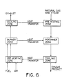
- Figure 6 is a block diagram of a methane reforming process which illustrates the present invention.
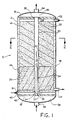
- the reaction apparatus 10 is shown generally in Figure 1. Although it is oriented vertically, it should be appreciated that it could be operated horizontally, and so is not limited to a particular orientation.
- the apparatus comprises a steel shell 12 lined inside with a refractory insulation material 14 having a bottom plate 16 (which may also be referred to as a tube sheet) sealed, by gaskets and bolting or the like, to the steel shell, and a top plate 18 (or top tube sheet), which together define the reaction vessel.
- the bottom plate 16 supports a catalyst bed 20 through which passes one or more combustion tubes 30, which are made of a ceramic material and are sealed to bottom plate 16 and top plate 18.
- the shape of the reformer 10 is generally cylindrical and could be described as somewhat similar in construction to a shell and tube heat exchanger.
- the ceramic burner tubes are sealed to plates 16 and 18 by a hollow screw (not shown) threaded into the tube sheet at the end of the tube in combination with a steel pressure ring which expands a graphite seal, preferably a graphite foil spiral wrapped annular cylinder seal (such as Grafoil brand foil from Union Carbide).
- a graphite seal preferably a graphite foil spiral wrapped annular cylinder seal (such as Grafoil brand foil from Union Carbide).
- each tube may be desirable to apply an axial compressive force or preload to each tube, which will tend to neutralize or subtract from the axial tensile stresses produced by heat flow, by incorporating, e.g., in the tube seal assembly a stack of Belleville type springs (not shown) or the like.
- the seals could be held in place by a device which also provides the axial compressive force.
- a feature of the present design is that it allows for the use of lower temperature seals where the combustion tube or tubes are joined to the tube sheet.
- Steel shell 12 has one or more feed inlets 22 for passing the feed gas mixture which is to be reformed into the reformer and down through the packed bed 20 to exit through one or more product outlet(s) 24.
- the feed gas mixture may be a mixture of natural gas and steam if the endothermic reaction is methane reforming reaction, although the mixture could be natural gas and water, which converts to steam in the reactor, or only natural gas, with the steam coming from water fed separately into the reactor.
- the catalytic bed 20 which can be nickel on an alumina, inert support, or other appropriate catalyst, could include an inert section or zone 26, or the entire bed could consist of a single catalyst material or plural catalyst materials. In fact, the apparatus could be operated without a catalyst for some endothermic reactions.
- a fuel feed tube 34 Located concentrically inside combustion tube 30 is a fuel feed tube 34, which can be made from a metal alloy or a ceramic material. Fuel feed tube 34 is fixed to,outer plate (or tube sheet) 35 by welding, using an o-ring or graphite foil seal 37. Fuel is fed from inlet 36 into fuel inlet manifold 38 to fuel feed tube 34. Air is fed via air inlet 40 to air inlet manifold 42 which is defined by outer plate 35 which is spaced apart from tube sheet 16 and which communicates with combustion tube 30 via annular inlet 44 so that air will flow in the annular space between the outer wall of fuel tube 34 and the inner wall of combustion tube 30. The combination of combustion tube 30 and fuel feed tube 34, constitute the heat generating means for the reactor.
- the fuel gas is any clean fuel to which sufficient water vapor has been added (if necessary) to prevent coking prior to its combustion. If the fuel contains a high carbon level, it will require some preheating to maintain the necessary humidity level without condensation.
- a resistance heating coil 46 is used inside the outer shell wall 12 of the reactor for cold starting the reactor.
- the resistance heater will preheat the adjacent zone to approximately 600°C (which will or less, depending upon the specific fuel being used), at which point auto-ignition of the fuel and air can occur. It may be necessary to flow air through until preheating is complete when the gas can be introduced to produce ignition in flame zone 50.
- the exhaust from combustion tube 30 is collected in exhaust manifold 52 and passes out exhaust outlet 54 which is in communication with manifold 52.
- the ceramic combustion tube 30 is preferably made from sintered allumina and can be made by any of the various, available processes for making and shaping dense (impervious) ceramic bodies. Also, there is no criticality in the use of alumina and other ceramic compositions can be used.
- U.S. Patent No. 4,346,049 to J.A. Coppola et al. teaches a silicon carbide composition and process for producing sintered alpha silicon carbide ceramic bodies, the teachings of which are incorporated herein by reference, and such could be used to make the ceramic tube.
- Other ceramic compositions that could be employed include silicon nitride, aluminum nitride, sialon, or the like. The exact material preferred will depend upon the reactants and reaction products involved in the process, as well as temperature and pressure conditions.
- the steel shell 12, bottom plate 16, top plate 18, manifolds 38 and 52, and outer plate 35 are preferably made of conventional pressure-vessel steel which is designed and rated for the reformer internal pressure of up 1200 psi or more and for temperatures of up to about 350°C.
- the refractory insulation 14 is preferably an erosion-resistant, low-conductivity type insulation such as an alumina composition with expansion joints used as required. The refractory should be rated for at least 1300°C continuous duty.
- FIG 2 shows a cross section of reformer 10 along lines 2-2 in Figure 1.
- fuel tube 34 is located concentrically within combustion tube 30 which in turn is surrounded by catalyst bed 20 inside insulated steel shell 12.
- the heat from combustion tube 30 will be transferred into catalyst bed 20 for effecting the endothermic reaction to reform the mixture of steam and light hydrocarbons.
- the use of external pressure surrounding the combustion tube 30 has the very significant advantage of placing the tube in a compressive stress state, where ceramics are much stronger than they are in tension.
- the design could consist of more than one burner tube with Figure 3 illustrating seven burner tubes in an appropriate pattern.
- the invention is not limited to the use of one or seven, and is contemplated that as many as many thousands of combustion tubes could be incorporated in an appropriate size reformer apparatus.
- the use of small-diameter ceramic combustion tubes and graphite foil seals facilitates a denser packing of burner tubes than has been previously available in prior art apparatus.
- the air supplied to inlet 40 could be supplied by a blower or a compressor depending upon the desired pressure drop, heat transfer requirements, and operation employed.
- a compressor will generate a higher inlet pressure than a blower, however, the cost of operating a blower would be less than operating a compressor.
- the apparatus shown in Figures 4 and 5 are basically similar to that shown in Figure 1 in that they include the shell 12, which contains a catalyst bed 20, and has feed inlet 22 and product outlet 24.
- the difference in these embodiments lies in the design of the heat generating means, although in each case, it is enclosed by the reaction vessel.
- combustion tube 30 has a feed gas tube 60 which has perforations or holes 64 at spaced intervals along its length and has one end 66 plugged or otherwise closed.
- fuel fed via inlet 36 into manifold 38 will pass down tube 60 until it exits via the perforations 64.
- the fuel will mix with the air fed via inlet 40 to manifold 42 and into the burner zone 68 and auto-ignite to heat the reactor.
- plug 66 need not resist very hot temperatures and thus could be made of graphite or heat resistant organic cement. Other methods for the staged introduction of the fuel could also be employed.
- the design in Figure 5 differs in that the heat generating means is a bayonet type heat generating means.
- the tube sheet is replaced by an insulated vessel closure 70 and the combustion tube is a closed end tube 80 sealed to plate 18.
- the combustion tube is shown with a closed end but it could be a plugged design as shown in Figure 4.
- the fuel is fed via fuel inlet 82 to fuel feed tube 84, while air is fed via air inlet 86 to air feed tube 88.
- the fuel will auto-ignite in flame zone 90 to produce the heat for conducting the endothermic reaction.
- the exhaust gases will pass up combustion tube 80, as shown by arrow 92 to manifold 52 where they exit the apparatus via exhaust line 54.
- the combustion tubes require a length to inside diameter ratio of typically 500 to 700 in order to achieve the required heat transfer per unit of flow volume for a natural gas plus steam reforming application. Even higher ratios are needed, it the reactor is to operate with low temperature differentials.
- the preferred tube separation distance is quite small; for example 0.3 to 0.5 inches. It is limited by the required sizes of the seals and their associated threads and the need to have some small distance between these threads. Small distances lead to smaller vessel sizes and improved shell-side heat transfer.
- the number of tubes in a single reactor could be as few as one to as many as 10,000 or more. Larger reactors will require thicker pressure-vessel walls, but will save on installation costs.
- the preferred tube wall thickness will depend upon tube strength, corrosion rates, and diameter.
- the use of external pressure will permit the use of relatively thin walls, since ceramics are much stronger in tension than compression.
- the preferred combustion tube inside diameter is usually equal to the tube separation distance (expressed as inside tube to inside tube surface).
- the preferred tube ID would be 0.4 inches for a centerline spacing of 0.8 inches.
- An equilateral triangular tube arrangement is preferred for maximum packing density.
- one design could use 10,000 tubes, each 0.4 inch ID x 0.5 inch OD x 20 feet long on 0.8 inch triangular pitch.
- the bundle diameter would be about 7 feet and the total inside-surface area would be about 20,900 square feet.
- the base-case embodiment employs a fuel and air stream entering the reactor at the same end where the process gas exits and flowing countercurrent to the process gas, with the exhaust leaving at the opposite end, where the process feed enters.
- Another variation would arrange cocurrent flow of combustion gases and process gases. This scheme would require a hot seal on the exhaust end of the ceramic tubes. Such a seal might be made of fused glass or a ceramic cement, for example.
- the cold-end seal could be an O-ring or graphite foil type to allow tube thermal expansion.
- Closed-end, triple-concentric combustion tubes might be used, with the combustion gas exiting at the same end of the reactor where the air and fuel enter. This is illustrated in Figure 5.
- the open ends of these concentric tubes might be at either the process feed or at the process exit end of the reactor.
- the reforming catalyst and its ceramic support particles must be chosen according to a number of criteria.
- the catalyst must maintain sufficient activity over a long period of time at the high bed temperatures. It should be strong enough to support the bed weight above it. It should have a particle size which is small enough to properly fill the spaces between the tubes but large enough to minimize pressure drop through the bed to an acceptable value. It should not sinter-bond excessively to itself or to the tubes upon long exposures at the high temperatures.
- a suitable form of nickel on alumina is one possible candidate, but other catalysts are also reported to be suitable.
- either a high-temperature shift catalyst and/or a low-temperature shift catalyst can optionally be placed within the reactor in the zone where the process gas is cooling and this will cause most of the CO to react with excess H2O to form more H2 with CO2 as a byproduct (the so-called "water-gas shift" reaction).
- syngas is desired for ammonia synthesis
- an appropriate (usually small) proportion of compressed air may be added to the natural gas and steam, such that the product syngas will contain the desired ratio of H2 to N2 (usually 3:1).
- This air addition will react in the catalyst bed during heatup, but will be low enough so as not to produce an excessive local temperature rise in the bed. The overall reaction will remain endothermic.
- This method for making ammonia syngas does not require the addition of any oxygen aside from the air itself, which is a desirable cost savings versus some competing processes which require the separation of oxygen from the air.
- Cold reactor preheat could be achieved alternatively by other means than the electric resistance heater shown.
- hot combustion gases could be introduced through supplementary nozzles in the reactor and circulated through the desired region.
- the upper operating temperature of the graphite foil seals is limited by oxidation by the air present on one side. If a controlled very slow leakage of process gas is permitted to occur through the seal, this could sweep this air away from the seal material and permit the seals to exhibit long life at higher temperatures. Such an arrangement may be termed a purged seal condition.
- thermal insulation might be used inside the pressure vessel.
- the maximum temperature of the combustion gases within the combustion tubes may be varied by adjusting the fuel composition and the fuel and air flow rates. Increasing the air flow rate progressively above the stoichiometric ratio will progressively lower the maximum local temperatures. Steam additions to the fuel can also reduce maximum temperatures.
- the reactor maximum process temperature can vary widely, as required. However, if the auto ignition condition is to be maintained, reactors using maximum process temperatures below about 500°C (depending upon the choice of fuel)'will normally require the selection of one of the closed-end combustion tube variants. In these cases, the maximum process temperature could be as low as perhaps 100°C.
- the reactor (shell-side) fluid could be of many different types, including gases, boiling liquids, liquids, or slurries containing fine solids. 'Gas to liquid condensation might also desirably occur in the coolest zone of the reactor.
- the combustion tubes might be made of various ceramics, depending upon the service conditions (temperature, corrosion,'stresses, etc.).
- alumina in addition to alumina, other possible materials for some applications would be carbide ceramics such as silicon carbide or other oxide ceramics such as mullite, stabilized zirconi, or the like.
- carbide ceramics such as silicon carbide or other oxide ceramics such as mullite, stabilized zirconi, or the like.
- the use of external pressure will be a major advantage in controlling the combined stresses in the ceramic tubes to acceptable levels.
- Still other materials are also possible, such as metal tubes for lower-temperature applications.
- a reforming catalyst might also be positioned within the tube 34 to cause the fuel to partially reform during its heatup and hence to both absorb more heat from the process gas (improving cooling) and to simultaneously increase the heating value of the fuel gas (improving heating).
- a feed containing 2.5 volumes steam plus 1.0 volume natural gas (with an assumed composition of 90 volume percent CH4, 7% C2H6, 2% N2, and 1% CO2) is passed through either a conventional reformer or this invention.
- the conventional reformer is similar to that described by Dwyer et al. (U.S. Patent No. 3,132,010) with a hot-zone reaction pressure of 155 psia, whereas the example of this invention uses 1070 psia for this pressure.
- the computed syngas compositions listed in Table 1 are based upon thermodynamic equilibrium compositions at the above pressures and at temperatures 20°C below the stated Table 1 peak temperatures. The compositions are tabulated after condensing water to 40°C.
- the advantages of the apparatus of the present invention are that the syngas pressure is much higher, thus eliminating or reducing the need for syngas compressors, the methane conversion percentage is much higher, the syngas CO/H2 ratio is much higher, and the syngas CO/CO2 ratio is much higher.
- the new process may, if desired, be operated at still higher temperatures to obtain still higher methane conversions, CO/H2 ratios, and CO/CO2 ratios. It may also be operated at either higher of lower pressures and/or steam ratios.
- the ceramic tubes are less prone to coking than are metallic tubes under conditions of low steam ratios.
- the new invention allows very high rates of heat transfer per unit of reactor vessel volume.
- the average rate of heat exchange between the process gas and the air/fuel/exhaust flow was calculated to be some 7 MW/m3 for the reformer internal volume for a reformer design in accordance with the present invention and based upon the stated example, and this figure is more than a factor of ten above the corresponding value for a typical radiant reformer.
Abstract
Description
- The present invention relates to apparatus used in conducting endothermic reactions, and particularly to furnaces for reforming light hydrocarbons, especially mixtures of steam and/or carbon dioxide and light hydrocarbons.
- Hydrogen for use in ammonia synthesis, methanol synthesis or hydrocracking plants, is frequently produced in a process using the following endothermic reforming reaction:

The hydrocarbon can be methane, which is shown in the above reaction, or other light hydrocarbons, or mixtures of these such as natural gas. The same reactions may also be employed where the desired product is CO or both CO and H₂. Another endothermic reaction is the conversion (pyrolysis) of ethane to ethylene which also produces the by-product hydrogen (H₂), and this reaction requires heat only, usually about 950°C and 3 atmospheres pressure, but needs no catalyst. The catalyst over which the methane reaction is carried out is, for example, nickel on an inert support, such as alumina, and is contained usually in vertical tubes which are supported in a furnace frequently called a "reforming furnace". Reforming furnaces are disclosed or schematically shown in the process flow diagrams of U.S. Patent Nos. 3,132,010; 3,264,066; and 3,382,044. - The tubes in the usual reforming furnaces extend vertically with reactants being fed by a manifold to one end of the set of tubes and product-rich gases being withdrawn from the other end of the tubes. Because the reforming reaction occurs at a high temperature and is endothermic, heat must be supplied to the tubes to heat the reactants. The reaction is carried out in the tubes at a high temperature of about 1500°F and at a pressure of about 150 to 450 psig.
- Various efforts have been made to improve the performance of the reforming furnace or to improve the structure of the furnace to facilitate the maintenance and operation of the furnace. For example, U.S. Patent No. 4,161,510 to A.J. Edridge teaches the use of a ceramic paint coating on the exposed surface of the reforming tubes in which the reaction is conducted, the paint being reflective to reduce fissure creep of the tubes. U.S. Patent No. 4,714,593 to A. Naito et al. teaches a reforming apparatus which uses a catalyzed heat generating apparatus to achieve miniaturization of the furnace. U.S. Patent No. 4,810,472 to S.P. Andrews et al. teaches a reforming apparatus which employs closed ended, double pass, externally heated, metal reformer tubes, also known as bayonet-tubes with controlled heat exchange between the product gas stream and the reactant stream across the wall of the tube.
- Apparatus is also known which employs ceramic tubes for carrying out gas reactions in those ceramic tubes. For example, U.S. Patent No. 2,987,382 to F. Endter et al. discloses such a ceramic tube furnace. Further, U.S. Patent No. 2,018,619 to F. Winkler et al. teaches tubes made from material containing elementary silicon which may be embedded in other gas-tight tubes and which prevents carbon formation in carrying out pyrogenic conversion of hydrocarbons.
- Known reforming furnaces are large and expensive, when measured as per unit of capacity, have tube lives shorter than would be desired, are prone to carbon deposition ("coking"), and must be frequently operated at temperatures below the ideally preferred values (for most efficient reactivity) due to the creep and corrosion behavior of their reforming tubes.
- The present invention employs a ceramic tube burner design which is enclosed by the reaction vessel in which the endothermic hydrocarbon reforming reaction takes place. This can be contrasted to with the usual prior art apparatus in which the reaction is done in the tube and the heatis supplied externally. The present design allows for a more compact apparatus which can employ a large number and high density of burner tubes and can operate at high temperatures and pressures to achieve high conversion of the hydrocarbon with high thermal efficiency of the process. Further, the materials of construction permit good operation with moderate steam-to-carbon ratios and minimal coking. The apparatus of the present invention allows for the use of relatively low-temperature seals.
- The reaction apparatus of the present invention includes a reaction vessel for effecting an endothermic reaction, having an input for feeding the feed gas mixture into the reaction vessel, and a discharge for removing the product gas from said reaction vessel and at least one heat generating means for heating said reaction vessel and being enclosed by said reaction vessel. The reaction vessel may contain a catalyst bed at least partially filling the reaction vessel to facilitate the endothermic reaction to produce a product gas. The heat generating means comprises at least one ceramic combustion tube concentrically surrounding a fuel feed tube which extends at least partially along the length and inside of the combustion tube. The heat generating means has inlets means for supplying fuel gas and air so the fuel gas and air will combust in said heat generating means and the heat which is generated will transfer from the heat generating means into the reaction vessel, and an exhaust outlet for removing the combustion exhaust gases from said heat generating means. Preferably, the feed gas mixture enters the reaction vessel at one end and the fuel gas and air enter the heat generating means at an opposite end from the feed end so that the flow of the reaction gases and the combustion gases are countercurrent.
- It is an object of the present invention to provide an improved apparatus for conducting endothermic reactions, such as reforming light-hydrocarbons, and which will provide improved conversions, energy efficiency, and maintenance.
- The present invention will become more apparent from the following description taken in conjunction with the accompanying drawings.
- Figure 1 is a cross sectional representation of the reforming apparatus of the present invention.
- Figure 2 is a cross sectional representation of the reforming apparatus of Figure 1 taken along
lines 2. - Figure 3 is a cross sectional representation similar to Figure 2 but showing another embodiment of the present invention.
- Figure 4 is a cross sectional representation, similar to Figure 1, of another embodiment of the invention which uses a perforated fuel feed tube.
- Figure 5 is a cross sectional representation of yet another embodiment of the present invention, which uses a bayonet combustion tube.
- Figure 6 is a block diagram of a methane reforming process which illustrates the present invention.
- The present invention is described more specifically with reference to the following preferred embodiments.
- The
reaction apparatus 10 is shown generally in Figure 1. Although it is oriented vertically, it should be appreciated that it could be operated horizontally, and so is not limited to a particular orientation. The apparatus comprises asteel shell 12 lined inside with arefractory insulation material 14 having a bottom plate 16 (which may also be referred to as a tube sheet) sealed, by gaskets and bolting or the like, to the steel shell, and a top plate 18 (or top tube sheet), which together define the reaction vessel. Thebottom plate 16 supports acatalyst bed 20 through which passes one ormore combustion tubes 30, which are made of a ceramic material and are sealed tobottom plate 16 andtop plate 18. The shape of thereformer 10 is generally cylindrical and could be described as somewhat similar in construction to a shell and tube heat exchanger. The ceramic burner tubes are sealed toplates seals 32 will hold the combustion tube in place, and contain the much higher shell side gas pressures, yet allow it to expand thermally and individually without significant gas flow leakage past the seals. Also, it may be desirable to apply an axial compressive force or preload to each tube, which will tend to neutralize or subtract from the axial tensile stresses produced by heat flow, by incorporating, e.g., in the tube seal assembly a stack of Belleville type springs (not shown) or the like. Alternatively, the seals could be held in place by a device which also provides the axial compressive force. A feature of the present design is that it allows for the use of lower temperature seals where the combustion tube or tubes are joined to the tube sheet. -
Steel shell 12 has one ormore feed inlets 22 for passing the feed gas mixture which is to be reformed into the reformer and down through thepacked bed 20 to exit through one or more product outlet(s) 24. The feed gas mixture, for example, may be a mixture of natural gas and steam if the endothermic reaction is methane reforming reaction, although the mixture could be natural gas and water, which converts to steam in the reactor, or only natural gas, with the steam coming from water fed separately into the reactor. As can be appreciated, other combinations of feed mixtures can be introduced. As illustrated in Figure 1, thecatalytic bed 20 which can be nickel on an alumina, inert support, or other appropriate catalyst, could include an inert section orzone 26, or the entire bed could consist of a single catalyst material or plural catalyst materials. In fact, the apparatus could be operated without a catalyst for some endothermic reactions. - Located concentrically inside
combustion tube 30 is afuel feed tube 34, which can be made from a metal alloy or a ceramic material.Fuel feed tube 34 is fixed to,outer plate (or tube sheet) 35 by welding, using an o-ring orgraphite foil seal 37. Fuel is fed frominlet 36 intofuel inlet manifold 38 tofuel feed tube 34. Air is fed viaair inlet 40 toair inlet manifold 42 which is defined byouter plate 35 which is spaced apart fromtube sheet 16 and which communicates withcombustion tube 30 viaannular inlet 44 so that air will flow in the annular space between the outer wall offuel tube 34 and the inner wall ofcombustion tube 30. The combination ofcombustion tube 30 andfuel feed tube 34, constitute the heat generating means for the reactor. - The fuel gas is any clean fuel to which sufficient water vapor has been added (if necessary) to prevent coking prior to its combustion. If the fuel contains a high carbon level, it will require some preheating to maintain the necessary humidity level without condensation.
- A
resistance heating coil 46 is used inside theouter shell wall 12 of the reactor for cold starting the reactor. The resistance heater will preheat the adjacent zone to approximately 600°C (which will or less, depending upon the specific fuel being used), at which point auto-ignition of the fuel and air can occur. It may be necessary to flow air through until preheating is complete when the gas can be introduced to produce ignition in flame zone 50. The exhaust fromcombustion tube 30 is collected inexhaust manifold 52 and passes outexhaust outlet 54 which is in communication withmanifold 52. - The
ceramic combustion tube 30 is preferably made from sintered allumina and can be made by any of the various, available processes for making and shaping dense (impervious) ceramic bodies. Also, there is no criticality in the use of alumina and other ceramic compositions can be used. For example, U.S. Patent No. 4,346,049 to J.A. Coppola et al. teaches a silicon carbide composition and process for producing sintered alpha silicon carbide ceramic bodies, the teachings of which are incorporated herein by reference, and such could be used to make the ceramic tube. Other ceramic compositions that could be employed include silicon nitride, aluminum nitride, sialon, or the like. The exact material preferred will depend upon the reactants and reaction products involved in the process, as well as temperature and pressure conditions. - The
steel shell 12,bottom plate 16,top plate 18,manifolds outer plate 35 are preferably made of conventional pressure-vessel steel which is designed and rated for the reformer internal pressure of up 1200 psi or more and for temperatures of up to about 350°C. Therefractory insulation 14 is preferably an erosion-resistant, low-conductivity type insulation such as an alumina composition with expansion joints used as required. The refractory should be rated for at least 1300°C continuous duty. - Figure 2 shows a cross section of
reformer 10 along lines 2-2 in Figure 1. As can be seenfuel tube 34 is located concentrically withincombustion tube 30 which in turn is surrounded bycatalyst bed 20 inside insulatedsteel shell 12. The heat fromcombustion tube 30 will be transferred intocatalyst bed 20 for effecting the endothermic reaction to reform the mixture of steam and light hydrocarbons. The use of external pressure surrounding thecombustion tube 30 has the very significant advantage of placing the tube in a compressive stress state, where ceramics are much stronger than they are in tension. - As shown in Figure 3, the design could consist of more than one burner tube with Figure 3 illustrating seven burner tubes in an appropriate pattern. The invention is not limited to the use of one or seven, and is contemplated that as many as many thousands of combustion tubes could be incorporated in an appropriate size reformer apparatus. The use of small-diameter ceramic combustion tubes and graphite foil seals facilitates a denser packing of burner tubes than has been previously available in prior art apparatus.
- The air supplied to
inlet 40 could be supplied by a blower or a compressor depending upon the desired pressure drop, heat transfer requirements, and operation employed. A compressor will generate a higher inlet pressure than a blower, however, the cost of operating a blower would be less than operating a compressor. Also, it may be desirable to preheat the air fed to the heat generating means. Although no preheater is illustrated, such devices are known in the art and are commercially available. If desired, the exhaust flow could be expanded (with possibly some added heat) through a gas turbine to drive the air compressor. - The apparatus shown in Figures 4 and 5 are basically similar to that shown in Figure 1 in that they include the
shell 12, which contains acatalyst bed 20, and has feedinlet 22 andproduct outlet 24. The difference in these embodiments lies in the design of the heat generating means, although in each case, it is enclosed by the reaction vessel. - As shown in Figure 4,
combustion tube 30 has afeed gas tube 60 which has perforations or holes 64 at spaced intervals along its length and has one end 66 plugged or otherwise closed. In this way, fuel fed viainlet 36 intomanifold 38 will pass downtube 60 until it exits via the perforations 64. When the reactor is at its operating temperature, the fuel will mix with the air fed viainlet 40 tomanifold 42 and into theburner zone 68 and auto-ignite to heat the reactor. Note that plug 66 need not resist very hot temperatures and thus could be made of graphite or heat resistant organic cement. Other methods for the staged introduction of the fuel could also be employed. - The design in Figure 5, differs in that the heat generating means is a bayonet type heat generating means. In this design, the tube sheet is replaced by an
insulated vessel closure 70 and the combustion tube is a closed end tube 80 sealed to plate 18. The combustion tube is shown with a closed end but it could be a plugged design as shown in Figure 4. The fuel is fed viafuel inlet 82 tofuel feed tube 84, while air is fed viaair inlet 86 toair feed tube 88. At operating temperature, the fuel will auto-ignite inflame zone 90 to produce the heat for conducting the endothermic reaction. The exhaust gases will pass up combustion tube 80, as shown byarrow 92 tomanifold 52 where they exit the apparatus viaexhaust line 54. - In general, for the apparatus of the present invention, the combustion tubes require a length to inside diameter ratio of typically 500 to 700 in order to achieve the required heat transfer per unit of flow volume for a natural gas plus steam reforming application. Even higher ratios are needed, it the reactor is to operate with low temperature differentials.
- The preferred tube separation distance is quite small; for example 0.3 to 0.5 inches. It is limited by the required sizes of the seals and their associated threads and the need to have some small distance between these threads. Small distances lead to smaller vessel sizes and improved shell-side heat transfer.
- The number of tubes in a single reactor could be as few as one to as many as 10,000 or more. Larger reactors will require thicker pressure-vessel walls, but will save on installation costs.
- The preferred tube wall thickness will depend upon tube strength, corrosion rates, and diameter. The use of external pressure will permit the use of relatively thin walls, since ceramics are much stronger in tension than compression.
- The preferred combustion tube inside diameter is usually equal to the tube separation distance (expressed as inside tube to inside tube surface). Thus, if the separation distance were 0.4 inches, the preferred tube ID would be 0.4 inches for a centerline spacing of 0.8 inches. An equilateral triangular tube arrangement is preferred for maximum packing density.
- For example, one design could use 10,000 tubes, each 0.4 inch ID x 0.5 inch OD x 20 feet long on 0.8 inch triangular pitch. The bundle diameter would be about 7 feet and the total inside-surface area would be about 20,900 square feet.
- The base-case embodiment employs a fuel and air stream entering the reactor at the same end where the process gas exits and flowing countercurrent to the process gas, with the exhaust leaving at the opposite end, where the process feed enters.
- Another variation would arrange cocurrent flow of combustion gases and process gases. This scheme would require a hot seal on the exhaust end of the ceramic tubes. Such a seal might be made of fused glass or a ceramic cement, for example. The cold-end seal could be an O-ring or graphite foil type to allow tube thermal expansion.
- Closed-end, triple-concentric combustion tubes might be used, with the combustion gas exiting at the same end of the reactor where the air and fuel enter. This is illustrated in Figure 5. The open ends of these concentric tubes might be at either the process feed or at the process exit end of the reactor.
- The reforming catalyst and its ceramic support particles must be chosen according to a number of criteria. The catalyst must maintain sufficient activity over a long period of time at the high bed temperatures. It should be strong enough to support the bed weight above it. It should have a particle size which is small enough to properly fill the spaces between the tubes but large enough to minimize pressure drop through the bed to an acceptable value. It should not sinter-bond excessively to itself or to the tubes upon long exposures at the high temperatures. A suitable form of nickel on alumina is one possible candidate, but other catalysts are also reported to be suitable.
- For hydrogen production, either a high-temperature shift catalyst and/or a low-temperature shift catalyst can optionally be placed within the reactor in the zone where the process gas is cooling and this will cause most of the CO to react with excess H₂O to form more H₂ with CO₂ as a byproduct (the so-called "water-gas shift" reaction).
- If syngas is desired for ammonia synthesis, an appropriate (usually small) proportion of compressed air may be added to the natural gas and steam, such that the product syngas will contain the desired ratio of H₂ to N₂ (usually 3:1). This air addition will react in the catalyst bed during heatup, but will be low enough so as not to produce an excessive local temperature rise in the bed. The overall reaction will remain endothermic. This method for making ammonia syngas does not require the addition of any oxygen aside from the air itself, which is a desirable cost savings versus some competing processes which require the separation of oxygen from the air.
- Cold reactor preheat could be achieved alternatively by other means than the electric resistance heater shown. For example, hot combustion gases could be introduced through supplementary nozzles in the reactor and circulated through the desired region.
- The upper operating temperature of the graphite foil seals is limited by oxidation by the air present on one side. If a controlled very slow leakage of process gas is permitted to occur through the seal, this could sweep this air away from the seal material and permit the seals to exhibit long life at higher temperatures. Such an arrangement may be termed a purged seal condition.
- Many different types of thermal insulation might be used inside the pressure vessel.
- The maximum temperature of the combustion gases within the combustion tubes may be varied by adjusting the fuel composition and the fuel and air flow rates. Increasing the air flow rate progressively above the stoichiometric ratio will progressively lower the maximum local temperatures. Steam additions to the fuel can also reduce maximum temperatures.
- The reactor maximum process temperature can vary widely, as required. However, if the auto ignition condition is to be maintained, reactors using maximum process temperatures below about 500°C (depending upon the choice of fuel)'will normally require the selection of one of the closed-end combustion tube variants. In these cases, the maximum process temperature could be as low as perhaps 100°C.
- The reactor (shell-side) fluid could be of many different types, including gases, boiling liquids, liquids, or slurries containing fine solids. 'Gas to liquid condensation might also desirably occur in the coolest zone of the reactor.
- The combustion tubes might be made of various ceramics, depending upon the service conditions (temperature, corrosion,'stresses, etc.). In addition to alumina, other possible materials for some applications would be carbide ceramics such as silicon carbide or other oxide ceramics such as mullite, stabilized zirconi, or the like. The use of external pressure will be a major advantage in controlling the combined stresses in the ceramic tubes to acceptable levels. Still other materials are also possible, such as metal tubes for lower-temperature applications.
- If the fuel chosen is a mixture of a hydrocarbon (such as natural gas) plus steam, a reforming catalyst might also be positioned within the
tube 34 to cause the fuel to partially reform during its heatup and hence to both absorb more heat from the process gas (improving cooling) and to simultaneously increase the heating value of the fuel gas (improving heating). - The following example is presented to illustrate the operation of an apparatus in accordance with the present invention and the advantages of very high temperature operation in producing syngas of superior composition. Modifications of the physical dimensions will alter the operating parameters and so adjustements may be necessary to achieve the same results.
- The flow diagram shown in Figure 6 is presented to help understand the example presented here and the various parameters involved in the process of the present invention.
- A feed containing 2.5 volumes steam plus 1.0 volume natural gas (with an assumed composition of 90 volume percent CH₄, 7% C₂H₆, 2% N₂, and 1% CO₂) is passed through either a conventional reformer or this invention. The conventional reformer is similar to that described by Dwyer et al. (U.S. Patent No. 3,132,010) with a hot-zone reaction pressure of 155 psia, whereas the example of this invention uses 1070 psia for this pressure. The computed syngas compositions listed in Table 1 are based upon thermodynamic equilibrium compositions at the above pressures and at
temperatures 20°C below the stated Table 1 peak temperatures. The compositions are tabulated after condensing water to 40°C.
- Based upon data from Table 1, the advantages of the apparatus of the present invention are that the syngas pressure is much higher, thus eliminating or reducing the need for syngas compressors, the methane conversion percentage is much higher, the syngas CO/H₂ ratio is much higher, and the syngas CO/CO₂ ratio is much higher.
- The new process may, if desired, be operated at still higher temperatures to obtain still higher methane conversions, CO/H₂ ratios, and CO/CO₂ ratios. It may also be operated at either higher of lower pressures and/or steam ratios. The ceramic tubes are less prone to coking than are metallic tubes under conditions of low steam ratios.
- The new invention allows very high rates of heat transfer per unit of reactor vessel volume. For example, the average rate of heat exchange between the process gas and the air/fuel/exhaust flow was calculated to be some 7 MW/m³ for the reformer internal volume for a reformer design in accordance with the present invention and based upon the stated example, and this figure is more than a factor of ten above the corresponding value for a typical radiant reformer.
- The invention has been described with respect to certain preferred embodiments. Various modifications and additions within the spirit of the invention will occur to or be made by those skilled in the art without departing from the concept of the invention. Therefore, the scope of the invention is to be determined by reference to the following claims.
Claims (20)
- A reaction apparatus comprising:
a reaction vessel for effecting an endothermic reaction, and
at least one heat generating means for heating said reaction vessel, said heat generating means enclosed by said reaction vessel;
said reaction vessel having an input means for feeding a feed gas to be subjected to the endothermic reaction which results in a product gas into said reaction vessel, and discharge means for removing product gas from said reaction vessel; and
said heat generating means comprising at least one ceramic combustion tube concentrically surrounding a fuel feed tube which extends at least partially along the length of and inside said combustion tube, said heat generating means having means for supplying fuel to said fuel feed tube and air to said combustion tube whereby said fuel will combust in said combustion tube and generate heat which is transferred into said reaction vessel by said combustion tube, and means for removing exhaust gases from said heat generating means. - The apparatus of claim 1 wherein said reaction vessel contains a catalyst bed at least partially filling said reaction vessel to facilitate the endothermic reaction.
- The apparatus of claim 1 wherein said feed gas enters said reaction vessel at a first end thereof and said fuel enters said heat generating means at an opposite end from said first end whereby the flow of the reaction and the combustion are countercurrent.
- The apparatus of claim 1 wherein said ceramic combustion tube is alumina.
- The apparatus of claim 1 wherein said ceramic combustion tube is selected from the group consisting of alumina, silicon carbide, aluminum nitride, silicon nitride, and sialon.
- The apparatus of claim 1 wherein there are multiple combustion tubes.
- The apparatus of claim 2 wherein said catalyst bed comprises at least two catalyst zones.
- The apparatus of claim 7 wherein at least one zone is an inert zone.
- The apparatus of claim 2 wherein said catalyst bed comprises a first section with a first catalyst for a first reaction and a second section with a second catalyst for a second reaction.
- The apparatus of claim 1 wherein said reaction vessel comprises a generally cylindrical shell surrounding said at least one combustion tube.
- The apparatus of claim 10 wherein said shell is metal.
- The apparatus of claim 10 wherein said shell further includes a layer of insulation on its inner surface.
- The apparatus of claim 1 further including means for preheating the air.
- The apparatus of claim 1 wherein said at least one combustion tube is mounted in contact with said reaction vessel by seals which allow said combustion tube to expand thermally.
- The apparatus of claim 14 wherein said seals are graphite seals.
- The apparatus of claim 14 wherein there are multiple tubes and each is free to expand thermally, independently of each other.
- The apparatus of claim 1 wherein there is an annular space between said combustion tube and said fuel feed tube and said air enters into said combustion tube via said annulus.
- The apparatus of claim 1 wherein said fuel feed tube comprises a metal tube.
- The apparatus of claim 1 wherein said fuel feed tube comprises a ceramic tube.
- The apparatus of claim 1 wherein the combustion tube is mounted by a means which applies an axial compressive force to the tubes.
Applications Claiming Priority (2)
| Application Number | Priority Date | Filing Date | Title |
|---|---|---|---|
| US50437590A | 1990-04-03 | 1990-04-03 | |
| US504375 | 1990-04-03 |
Publications (2)
| Publication Number | Publication Date |
|---|---|
| EP0450872A1 true EP0450872A1 (en) | 1991-10-09 |
| EP0450872B1 EP0450872B1 (en) | 1994-11-23 |
Family
ID=24006004
Family Applications (1)
| Application Number | Title | Priority Date | Filing Date |
|---|---|---|---|
| EP91302767A Expired - Lifetime EP0450872B1 (en) | 1990-04-03 | 1991-03-28 | Endothermic reaction apparatus |
Country Status (10)
| Country | Link |
|---|---|
| EP (1) | EP0450872B1 (en) |
| JP (1) | JP3075757B2 (en) |
| KR (1) | KR0170398B1 (en) |
| AT (1) | ATE114253T1 (en) |
| AU (2) | AU7356491A (en) |
| BR (1) | BR9101266A (en) |
| CA (1) | CA2038289C (en) |
| DE (1) | DE69105230T2 (en) |
| DK (1) | DK0450872T3 (en) |
| ZA (1) | ZA911838B (en) |
Cited By (24)
| Publication number | Priority date | Publication date | Assignee | Title |
|---|---|---|---|---|
| US5565009A (en) * | 1990-04-03 | 1996-10-15 | The Standard Oil Company | Endothermic reaction process |
| US5567398A (en) * | 1990-04-03 | 1996-10-22 | The Standard Oil Company | Endothermic reaction apparatus and method |
| EP0841301A1 (en) * | 1996-11-12 | 1998-05-13 | Ammonia Casale S.A. | Reforming apparatus |
| DE19813053A1 (en) * | 1998-03-25 | 1999-09-30 | Dbb Fuel Cell Engines Gmbh | Reactor unit for a catalytic chemical reaction, especially for catalytic methanol reforming |
| US6096106A (en) * | 1990-04-03 | 2000-08-01 | The Standard Oil Company | Endothermic reaction apparatus |
| US6153152A (en) * | 1990-04-03 | 2000-11-28 | The Standard Oil Company | Endothermic reaction apparatus and method |
| EP1136444A1 (en) * | 2000-03-22 | 2001-09-26 | Ammonia Casale S.A. | Process for obtaining a heating fluid as indirect heat source for carrying out endothermic reactions |
| JP2001354403A (en) * | 2000-04-13 | 2001-12-25 | L'air Liquide | Manufacturing method for mixture containing hydrogen and co |
| US6375924B1 (en) | 1998-12-11 | 2002-04-23 | Uop Llc | Water gas shift process for purifying hydrogen for use with fuel cells |
| EP1249272A1 (en) * | 2001-04-11 | 2002-10-16 | Ammonia Casale S.A. | Sealing means for chemical reactor |
| AU775023B2 (en) * | 1996-11-12 | 2004-07-15 | Ammonia Casale S.A. | Use of a seal of the compression ring type |
| US7025940B2 (en) * | 1997-10-08 | 2006-04-11 | Shell Oil Company | Flameless combustor process heater |
| WO2006061121A1 (en) * | 2004-12-08 | 2006-06-15 | Lurgi Ag | Method and device for producing a synthesis gas containing h2 and co |
| WO2006099047A1 (en) * | 2005-03-10 | 2006-09-21 | Shell Internationale Research Maatschappij B.V. | A multi-tube heat transfer system for the combustion of a fuel and heating of a process fluid and the use thereof |
| WO2006099034A1 (en) * | 2005-03-10 | 2006-09-21 | Shell Internationale Research Maatschappij B.V. | A heat transfer system for the combustion of a fuel and heating of a process fluid and a process that uses same |
| EP1772427A1 (en) * | 2004-06-02 | 2007-04-11 | Ebara Ballard Corporation | Fuel treating device |
| EP2329556A1 (en) * | 2008-08-26 | 2011-06-08 | IdaTech, LLC | Fuel cell systems including hydrogen-producing assemblies |
| US8016589B2 (en) | 2005-03-10 | 2011-09-13 | Shell Oil Company | Method of starting up a direct heating system for the flameless combustion of fuel and direct heating of a process fluid |
| CN102829181A (en) * | 2011-06-16 | 2012-12-19 | 阿梅尼亚·卡萨莱股份有限公司 | Sealing device used for chemical reactor |
| ITVR20120101A1 (en) * | 2012-05-18 | 2013-11-19 | I C I Caldaie S P A | CHEMICAL REACTOR STRUCTURE |
| WO2018046590A1 (en) | 2016-09-09 | 2018-03-15 | Shell Internationale Research Maatschappij B.V. | Process for the preparation of hydrogen |
| CN110545907A (en) * | 2017-04-25 | 2019-12-06 | 宾哈利姆拉希普·阿明 | Reaction chamber for exothermic and endothermic reactions |
| CN110947354A (en) * | 2019-12-31 | 2020-04-03 | 淮阴工学院 | Methane hydrochlorination reactor |
| WO2023274939A1 (en) * | 2021-06-28 | 2023-01-05 | Topsoe A/S | A structured catalyst |
Families Citing this family (11)
| Publication number | Priority date | Publication date | Assignee | Title |
|---|---|---|---|---|
| US6616909B1 (en) * | 1998-07-27 | 2003-09-09 | Battelle Memorial Institute | Method and apparatus for obtaining enhanced production rate of thermal chemical reactions |
| DE19855769B4 (en) * | 1998-12-03 | 2008-10-09 | Nucellsys Gmbh | Catalytically heated component for a chemical reactor |
| US6162267A (en) * | 1998-12-11 | 2000-12-19 | Uop Llc | Process for the generation of pure hydrogen for use with fuel cells |
| JP2002326805A (en) * | 2001-04-27 | 2002-11-12 | Daikin Ind Ltd | Reformer and fuel cell system which is equipped with this |
| JP4762496B2 (en) * | 2004-01-06 | 2011-08-31 | 東京瓦斯株式会社 | Catalytic reactor |
| FR2914395B1 (en) * | 2007-03-30 | 2009-11-20 | Inst Francais Du Petrole | NEW COMPACT EXCHANGER REACTOR USING A POROUS BURNER |
| US8441361B2 (en) | 2010-02-13 | 2013-05-14 | Mcallister Technologies, Llc | Methods and apparatuses for detection of properties of fluid conveyance systems |
| EP2534095A2 (en) * | 2010-02-13 | 2012-12-19 | McAlister Technologies, LLC | Reactor vessels with transmissive surfaces for producing hydrogen-based fuels and structural elements, and associated systems and methods |
| CN102869873B (en) * | 2010-02-13 | 2015-05-06 | 麦卡利斯特技术有限责任公司 | Coupled thermochemical reactors and engines, and associated systems and methods |
| WO2013025650A1 (en) | 2011-08-12 | 2013-02-21 | Mcalister Technologies, Llc | Mobile transport platforms for producing hydrogen and structural materials and associated systems and methods |
| US10106406B2 (en) | 2013-11-06 | 2018-10-23 | Watt Fuel Cell Corp. | Chemical reactor with manifold for management of a flow of gaseous reaction medium thereto |
Citations (3)
| Publication number | Priority date | Publication date | Assignee | Title |
|---|---|---|---|---|
| GB1039756A (en) * | 1962-10-29 | 1966-08-24 | Gas Council | Improvements in or relating to methods of treating gases |
| US4157241A (en) * | 1976-03-29 | 1979-06-05 | Avion Manufacturing Co. | Furnace heating assembly and method of making the same |
| GB2050413A (en) * | 1979-05-18 | 1981-01-07 | Toyo Engineering Corp | Process for hydrocarbon reforming and apparatus therefor |
-
1991
- 1991-03-13 ZA ZA911838A patent/ZA911838B/en unknown
- 1991-03-14 AU AU73564/91A patent/AU7356491A/en not_active Abandoned
- 1991-03-14 CA CA002038289A patent/CA2038289C/en not_active Expired - Fee Related
- 1991-03-28 BR BR9101266-0A patent/BR9101266A/en not_active IP Right Cessation
- 1991-03-28 EP EP91302767A patent/EP0450872B1/en not_active Expired - Lifetime
- 1991-03-28 AT AT91302767T patent/ATE114253T1/en not_active IP Right Cessation
- 1991-03-28 DK DK91302767.8T patent/DK0450872T3/en active
- 1991-03-28 DE DE69105230T patent/DE69105230T2/en not_active Expired - Fee Related
- 1991-04-02 JP JP03070019A patent/JP3075757B2/en not_active Expired - Fee Related
- 1991-04-02 KR KR1019910005313A patent/KR0170398B1/en not_active IP Right Cessation
-
1995
- 1995-11-09 AU AU37774/95A patent/AU698930B2/en not_active Ceased
Patent Citations (3)
| Publication number | Priority date | Publication date | Assignee | Title |
|---|---|---|---|---|
| GB1039756A (en) * | 1962-10-29 | 1966-08-24 | Gas Council | Improvements in or relating to methods of treating gases |
| US4157241A (en) * | 1976-03-29 | 1979-06-05 | Avion Manufacturing Co. | Furnace heating assembly and method of making the same |
| GB2050413A (en) * | 1979-05-18 | 1981-01-07 | Toyo Engineering Corp | Process for hydrocarbon reforming and apparatus therefor |
Cited By (43)
| Publication number | Priority date | Publication date | Assignee | Title |
|---|---|---|---|---|
| US5567398A (en) * | 1990-04-03 | 1996-10-22 | The Standard Oil Company | Endothermic reaction apparatus and method |
| US6096106A (en) * | 1990-04-03 | 2000-08-01 | The Standard Oil Company | Endothermic reaction apparatus |
| US6153152A (en) * | 1990-04-03 | 2000-11-28 | The Standard Oil Company | Endothermic reaction apparatus and method |
| US5565009A (en) * | 1990-04-03 | 1996-10-15 | The Standard Oil Company | Endothermic reaction process |
| EP0703823B1 (en) * | 1993-06-16 | 1999-08-04 | The Standard Oil Company | Endothermic reaction apparatus |
| US6426054B1 (en) | 1996-11-12 | 2002-07-30 | Amonia Casale S.A. | Reforming apparatus |
| EP0841301A1 (en) * | 1996-11-12 | 1998-05-13 | Ammonia Casale S.A. | Reforming apparatus |
| EP1138630A2 (en) * | 1996-11-12 | 2001-10-04 | Ammonia Casale S.A. | Seal for use in reforming apparatus |
| AU775023B2 (en) * | 1996-11-12 | 2004-07-15 | Ammonia Casale S.A. | Use of a seal of the compression ring type |
| EP1138630A3 (en) * | 1996-11-12 | 2003-04-02 | Ammonia Casale S.A. | Seal for use in reforming apparatus |
| US7108730B2 (en) * | 1997-10-08 | 2006-09-19 | Shell Oil Company | Method for providing controlled heat to a process |
| US7025940B2 (en) * | 1997-10-08 | 2006-04-11 | Shell Oil Company | Flameless combustor process heater |
| DE19813053C2 (en) * | 1998-03-25 | 2001-10-18 | Xcellsis Gmbh | Reactor unit for a catalytic chemical reaction, especially for catalytic methanol reforming |
| US6180081B1 (en) | 1998-03-25 | 2001-01-30 | Xcellsis Gmbh | Reactor unit for a catalytic chemical reaction, especially for a catalyzing methanol reformer |
| DE19813053A1 (en) * | 1998-03-25 | 1999-09-30 | Dbb Fuel Cell Engines Gmbh | Reactor unit for a catalytic chemical reaction, especially for catalytic methanol reforming |
| US6409974B1 (en) | 1998-12-11 | 2002-06-25 | Uop Llc | Water gas shift process and apparatus for purifying hydrogen for use with fuel cells |
| US6375924B1 (en) | 1998-12-11 | 2002-04-23 | Uop Llc | Water gas shift process for purifying hydrogen for use with fuel cells |
| US7465324B2 (en) | 2000-03-22 | 2008-12-16 | Ammonia Casale S.A. | Process for obtaining a heating fluid as indirect heat source for carrying out reforming reactions |
| EP1136444A1 (en) * | 2000-03-22 | 2001-09-26 | Ammonia Casale S.A. | Process for obtaining a heating fluid as indirect heat source for carrying out endothermic reactions |
| JP2001354403A (en) * | 2000-04-13 | 2001-12-25 | L'air Liquide | Manufacturing method for mixture containing hydrogen and co |
| EP1249272A1 (en) * | 2001-04-11 | 2002-10-16 | Ammonia Casale S.A. | Sealing means for chemical reactor |
| WO2002083287A1 (en) * | 2001-04-11 | 2002-10-24 | Ammonia Casale S.A. | Sealing means for chemical reactor |
| US7524468B2 (en) | 2001-04-11 | 2009-04-28 | Ammonia Casale S.A. | Sealing means for chemical reactor |
| EP1772427A4 (en) * | 2004-06-02 | 2011-05-25 | Ebara Corp | Fuel treating device |
| EP1772427A1 (en) * | 2004-06-02 | 2007-04-11 | Ebara Ballard Corporation | Fuel treating device |
| WO2006061121A1 (en) * | 2004-12-08 | 2006-06-15 | Lurgi Ag | Method and device for producing a synthesis gas containing h2 and co |
| US8465563B2 (en) | 2004-12-08 | 2013-06-18 | Lurgi Ag | Method and device for producing a synthesis gas containing H2 and CO |
| US8016589B2 (en) | 2005-03-10 | 2011-09-13 | Shell Oil Company | Method of starting up a direct heating system for the flameless combustion of fuel and direct heating of a process fluid |
| WO2006099034A1 (en) * | 2005-03-10 | 2006-09-21 | Shell Internationale Research Maatschappij B.V. | A heat transfer system for the combustion of a fuel and heating of a process fluid and a process that uses same |
| CN101163917B (en) * | 2005-03-10 | 2010-05-19 | 国际壳牌研究有限公司 | Multi-tube heat transfer system for the combustion of a fuel and heating of a process fluid and the use thereof |
| US7651331B2 (en) | 2005-03-10 | 2010-01-26 | Shell Oil Company | Multi-tube heat transfer system for the combustion of a fuel and heating of a process fluid and the use thereof |
| US7704070B2 (en) | 2005-03-10 | 2010-04-27 | Shell Oil Company | Heat transfer system for the combustion of a fuel heating of a process fluid and a process that uses same |
| WO2006099047A1 (en) * | 2005-03-10 | 2006-09-21 | Shell Internationale Research Maatschappij B.V. | A multi-tube heat transfer system for the combustion of a fuel and heating of a process fluid and the use thereof |
| EP2329556A1 (en) * | 2008-08-26 | 2011-06-08 | IdaTech, LLC | Fuel cell systems including hydrogen-producing assemblies |
| EP2329556A4 (en) * | 2008-08-26 | 2014-04-16 | Idatech Llc | Fuel cell systems including hydrogen-producing assemblies |
| CN102829181A (en) * | 2011-06-16 | 2012-12-19 | 阿梅尼亚·卡萨莱股份有限公司 | Sealing device used for chemical reactor |
| ITVR20120101A1 (en) * | 2012-05-18 | 2013-11-19 | I C I Caldaie S P A | CHEMICAL REACTOR STRUCTURE |
| WO2018046590A1 (en) | 2016-09-09 | 2018-03-15 | Shell Internationale Research Maatschappij B.V. | Process for the preparation of hydrogen |
| AU2017324397B2 (en) * | 2016-09-09 | 2020-02-27 | Shell Internationale Research Maatschappij B.V. | Process for the preparation of hydrogen |
| US11161738B2 (en) | 2016-09-09 | 2021-11-02 | Shell Oil Company | Process for the preparation of hydrogen |
| CN110545907A (en) * | 2017-04-25 | 2019-12-06 | 宾哈利姆拉希普·阿明 | Reaction chamber for exothermic and endothermic reactions |
| CN110947354A (en) * | 2019-12-31 | 2020-04-03 | 淮阴工学院 | Methane hydrochlorination reactor |
| WO2023274939A1 (en) * | 2021-06-28 | 2023-01-05 | Topsoe A/S | A structured catalyst |
Also Published As
| Publication number | Publication date |
|---|---|
| KR910018071A (en) | 1991-11-30 |
| EP0450872B1 (en) | 1994-11-23 |
| DE69105230T2 (en) | 1995-05-18 |
| DE69105230D1 (en) | 1995-01-05 |
| KR0170398B1 (en) | 1999-01-15 |
| ATE114253T1 (en) | 1994-12-15 |
| AU3777495A (en) | 1996-01-18 |
| CA2038289A1 (en) | 1991-10-04 |
| BR9101266A (en) | 1991-11-26 |
| AU698930B2 (en) | 1998-11-12 |
| ZA911838B (en) | 1991-12-24 |
| CA2038289C (en) | 2002-02-19 |
| JP3075757B2 (en) | 2000-08-14 |
| JPH0596149A (en) | 1993-04-20 |
| AU7356491A (en) | 1991-12-19 |
| DK0450872T3 (en) | 1994-12-12 |
Similar Documents
| Publication | Publication Date | Title |
|---|---|---|
| EP0450872B1 (en) | Endothermic reaction apparatus | |
| AU661877B2 (en) | Endothermic reaction apparatus | |
| US6096106A (en) | Endothermic reaction apparatus | |
| EP0703823B1 (en) | Endothermic reaction apparatus | |
| US5229102A (en) | Catalytic ceramic membrane steam-hydrocarbon reformer | |
| US8273314B2 (en) | Internal combustion exchanger-reactor for fixed bed endothermic reaction | |
| US5112578A (en) | Reactor for reforming hydrocarbon and process for reforming hydrocarbon | |
| US4981676A (en) | Catalytic ceramic membrane steam/hydrocarbon reformer | |
| US4909809A (en) | Apparatus for the production of gas | |
| KR20050112527A (en) | Hydrogen manufacture using pressure swing reforming | |
| US5156821A (en) | Reactor for reforming hydrocarbon | |
| US6153152A (en) | Endothermic reaction apparatus and method | |
| JP3834069B2 (en) | Endothermic reactor | |
| JP2003520747A (en) | Steam reformer | |
| JP4850696B2 (en) | Hydrogen production using pressure swing reforming | |
| JPH10273304A (en) | Heat exchange type reformer | |
| CA2310482A1 (en) | Reactor for carrying out a non-adiabatic process | |
| KR100241568B1 (en) | Endothermic reaction process | |
| JPS61232203A (en) | Generation of hydrogen containing gas | |
| NZ245475A (en) | Endothermic reaction vessel with metallic reaction tube in thermal contact with combustion zone | |
| SA93140127B1 (en) | An endothermic reaction process | |
| JPS62201632A (en) | Reformer |
Legal Events
| Date | Code | Title | Description |
|---|---|---|---|
| PUAI | Public reference made under article 153(3) epc to a published international application that has entered the european phase |
Free format text: ORIGINAL CODE: 0009012 |
|
| AK | Designated contracting states |
Kind code of ref document: A1 Designated state(s): AT BE CH DE DK ES FR GB GR IT LI LU NL SE |
|
| 17P | Request for examination filed |
Effective date: 19920316 |
|
| 17Q | First examination report despatched |
Effective date: 19921127 |
|
| GRAA | (expected) grant |
Free format text: ORIGINAL CODE: 0009210 |
|
| AK | Designated contracting states |
Kind code of ref document: B1 Designated state(s): AT BE CH DE DK ES FR GB GR IT LI LU NL SE |
|
| PG25 | Lapsed in a contracting state [announced via postgrant information from national office to epo] |
Ref country code: CH Effective date: 19941123 Ref country code: NL Effective date: 19941123 Ref country code: GR Free format text: LAPSE BECAUSE OF FAILURE TO SUBMIT A TRANSLATION OF THE DESCRIPTION OR TO PAY THE FEE WITHIN THE PRESCRIBED TIME-LIMIT Effective date: 19941123 Ref country code: ES Free format text: THE PATENT HAS BEEN ANNULLED BY A DECISION OF A NATIONAL AUTHORITY Effective date: 19941123 Ref country code: BE Effective date: 19941123 Ref country code: AT Effective date: 19941123 Ref country code: LI Effective date: 19941123 |
|
| REF | Corresponds to: |
Ref document number: 114253 Country of ref document: AT Date of ref document: 19941215 Kind code of ref document: T |
|
| REG | Reference to a national code |
Ref country code: DK Ref legal event code: T3 |
|
| ITF | It: translation for a ep patent filed |
Owner name: ING. C. GREGORJ S.P.A. |
|
| REF | Corresponds to: |
Ref document number: 69105230 Country of ref document: DE Date of ref document: 19950105 |
|
| ET | Fr: translation filed | ||
| PG25 | Lapsed in a contracting state [announced via postgrant information from national office to epo] |
Ref country code: SE Effective date: 19950223 |
|
| REG | Reference to a national code |
Ref country code: CH Ref legal event code: PL |
|
| PG25 | Lapsed in a contracting state [announced via postgrant information from national office to epo] |
Ref country code: LU Free format text: LAPSE BECAUSE OF NON-PAYMENT OF DUE FEES Effective date: 19950331 |
|
| NLV1 | Nl: lapsed or annulled due to failure to fulfill the requirements of art. 29p and 29m of the patents act | ||
| PLBE | No opposition filed within time limit |
Free format text: ORIGINAL CODE: 0009261 |
|
| STAA | Information on the status of an ep patent application or granted ep patent |
Free format text: STATUS: NO OPPOSITION FILED WITHIN TIME LIMIT |
|
| 26N | No opposition filed | ||
| REG | Reference to a national code |
Ref country code: GB Ref legal event code: IF02 |
|
| PGFP | Annual fee paid to national office [announced via postgrant information from national office to epo] |
Ref country code: DK Payment date: 20040123 Year of fee payment: 14 |
|
| PGFP | Annual fee paid to national office [announced via postgrant information from national office to epo] |
Ref country code: DE Payment date: 20040212 Year of fee payment: 14 |
|
| PGFP | Annual fee paid to national office [announced via postgrant information from national office to epo] |
Ref country code: FR Payment date: 20040216 Year of fee payment: 14 |
|
| PG25 | Lapsed in a contracting state [announced via postgrant information from national office to epo] |
Ref country code: IT Free format text: LAPSE BECAUSE OF NON-PAYMENT OF DUE FEES;WARNING: LAPSES OF ITALIAN PATENTS WITH EFFECTIVE DATE BEFORE 2007 MAY HAVE OCCURRED AT ANY TIME BEFORE 2007. THE CORRECT EFFECTIVE DATE MAY BE DIFFERENT FROM THE ONE RECORDED. Effective date: 20050328 |
|
| PG25 | Lapsed in a contracting state [announced via postgrant information from national office to epo] |
Ref country code: DK Free format text: LAPSE BECAUSE OF NON-PAYMENT OF DUE FEES Effective date: 20050331 |
|
| PG25 | Lapsed in a contracting state [announced via postgrant information from national office to epo] |
Ref country code: DE Free format text: LAPSE BECAUSE OF NON-PAYMENT OF DUE FEES Effective date: 20051001 |
|
| PG25 | Lapsed in a contracting state [announced via postgrant information from national office to epo] |
Ref country code: FR Free format text: LAPSE BECAUSE OF NON-PAYMENT OF DUE FEES Effective date: 20051130 |
|
| REG | Reference to a national code |
Ref country code: DK Ref legal event code: EBP |
|
| REG | Reference to a national code |
Ref country code: FR Ref legal event code: ST Effective date: 20051130 |
|
| PGFP | Annual fee paid to national office [announced via postgrant information from national office to epo] |
Ref country code: GB Payment date: 20100326 Year of fee payment: 20 |
|
| REG | Reference to a national code |
Ref country code: GB Ref legal event code: PE20 Expiry date: 20110327 |
|
| PG25 | Lapsed in a contracting state [announced via postgrant information from national office to epo] |
Ref country code: GB Free format text: LAPSE BECAUSE OF EXPIRATION OF PROTECTION Effective date: 20110327 |