EP0451063A1 - Apparatus for quickly cooling packaged products, especially bottles - Google Patents
Apparatus for quickly cooling packaged products, especially bottles Download PDFInfo
- Publication number
- EP0451063A1 EP0451063A1 EP91420104A EP91420104A EP0451063A1 EP 0451063 A1 EP0451063 A1 EP 0451063A1 EP 91420104 A EP91420104 A EP 91420104A EP 91420104 A EP91420104 A EP 91420104A EP 0451063 A1 EP0451063 A1 EP 0451063A1
- Authority
- EP
- European Patent Office
- Prior art keywords
- enclosure
- support
- products
- slides
- Prior art date
- Legal status (The legal status is an assumption and is not a legal conclusion. Google has not performed a legal analysis and makes no representation as to the accuracy of the status listed.)
- Withdrawn
Links
Images


Classifications
-
- F—MECHANICAL ENGINEERING; LIGHTING; HEATING; WEAPONS; BLASTING
- F25—REFRIGERATION OR COOLING; COMBINED HEATING AND REFRIGERATION SYSTEMS; HEAT PUMP SYSTEMS; MANUFACTURE OR STORAGE OF ICE; LIQUEFACTION SOLIDIFICATION OF GASES
- F25D—REFRIGERATORS; COLD ROOMS; ICE-BOXES; COOLING OR FREEZING APPARATUS NOT OTHERWISE PROVIDED FOR
- F25D17/00—Arrangements for circulating cooling fluids; Arrangements for circulating gas, e.g. air, within refrigerated spaces
- F25D17/02—Arrangements for circulating cooling fluids; Arrangements for circulating gas, e.g. air, within refrigerated spaces for circulating liquids, e.g. brine
-
- F—MECHANICAL ENGINEERING; LIGHTING; HEATING; WEAPONS; BLASTING
- F25—REFRIGERATION OR COOLING; COMBINED HEATING AND REFRIGERATION SYSTEMS; HEAT PUMP SYSTEMS; MANUFACTURE OR STORAGE OF ICE; LIQUEFACTION SOLIDIFICATION OF GASES
- F25D—REFRIGERATORS; COLD ROOMS; ICE-BOXES; COOLING OR FREEZING APPARATUS NOT OTHERWISE PROVIDED FOR
- F25D31/00—Other cooling or freezing apparatus
- F25D31/006—Other cooling or freezing apparatus specially adapted for cooling receptacles, e.g. tanks
- F25D31/007—Bottles or cans
-
- F—MECHANICAL ENGINEERING; LIGHTING; HEATING; WEAPONS; BLASTING
- F25—REFRIGERATION OR COOLING; COMBINED HEATING AND REFRIGERATION SYSTEMS; HEAT PUMP SYSTEMS; MANUFACTURE OR STORAGE OF ICE; LIQUEFACTION SOLIDIFICATION OF GASES
- F25D—REFRIGERATORS; COLD ROOMS; ICE-BOXES; COOLING OR FREEZING APPARATUS NOT OTHERWISE PROVIDED FOR
- F25D2331/00—Details or arrangements of other cooling or freezing apparatus not provided for in other groups of this subclass
- F25D2331/80—Type of cooled receptacles
- F25D2331/803—Bottles
-
- F—MECHANICAL ENGINEERING; LIGHTING; HEATING; WEAPONS; BLASTING
- F25—REFRIGERATION OR COOLING; COMBINED HEATING AND REFRIGERATION SYSTEMS; HEAT PUMP SYSTEMS; MANUFACTURE OR STORAGE OF ICE; LIQUEFACTION SOLIDIFICATION OF GASES
- F25D—REFRIGERATORS; COLD ROOMS; ICE-BOXES; COOLING OR FREEZING APPARATUS NOT OTHERWISE PROVIDED FOR
- F25D2400/00—General features of, or devices for refrigerators, cold rooms, ice-boxes, or for cooling or freezing apparatus not covered by any other subclass
- F25D2400/28—Quick cooling
Definitions
- the present invention relates to an improvement made to installations making it possible to rapidly cool, or even to freeze (or conversely to reheat) various products, in particular liquids such as drinks stored in bottles.
- various products in particular liquids such as drinks stored in bottles.
- the invention will be described for the treatment of liquids stored in bottles, but it is obvious that this is not limiting and that the installation according to the invention could be used for stored products in other forms (for example in the form of sachets, metal or cardboard boxes), or even for solid products.
- the upper part of the bottle is not in contact with the wall of the envelope and its installation and removal can be difficult to carry out, because it must be introduced "in force” if it is of a diameter corresponding substantially to the diameter of the envelope, while in the case of small bottles, as said above, the envelope will not press against the periphery, and moreover this will involve carrying out the establishment and removal of the bottle manually by plunging the hand inside the envelope.
- the invention not only makes it possible to solve the aforementioned problems, but also makes it possible to solve a problem that has not yet been posed or resolved, which is that of being able to produce an assembly allowing a programmed heat exchange duration, and requiring no monitoring of from the user.
- the invention therefore relates to an improvement made to installations making it possible to rapidly cool various products stored in particular inside a bottle of the type constituted by a tray, placed inside a insulating enclosure, and which contains a liquid maintained at very low temperature by means of a refrigerant circuit, the keeping inside the refrigerating medium of the products to be cooled being obtained by means of "pockets" which plunge inside the fluid refrigerant and inside which the products to be cooled are arranged, and it is characterized in that the bag (s) is (are) in the form of an envelope open at its upper part, based of a flexible waterproof plastic film, maintained along their open area at the upper part of the enclosure, and whose closed base is associated with means making it possible to move it from the upper part open open near the bottom of the enclosure and vice versa.
- the installation and removal of the bottles to be cooled can be carried out not only in a very simple manner, since in the high position, the pocket is folded and therefore does not grip the bottle, then that in the submerged position, it presses perfectly against the periphery of said bottle.
- the means for moving the pocket consist of a set of slides along which slides a support disposed below the lower surface of the pocket. This support can be associated with a float, the positioning of the product inside the refrigerating chamber being obtained by means of a push, and the ascent after maintenance for a determined period is carried out freely by the simple principle Archimedes.
- one of the slides will be in the form of a threaded rod passing inside a bearing in the form of a nut associated with the support, the rotary drive of the rod by means of an electric gear motor making it possible to lower and mount said support positively.
- the installation according to the invention consists of an isothermal tank (1) provided with a refrigerant circuit (2) now at very low temperature a liquid (3), consisting of an unfrozen solution, such as for example a brine.
- a liquid (3) consisting of an unfrozen solution, such as for example a brine.
- said pockets (4) consist of a waterproof plastic film, such as for example a polyethylene film, the open upper part (6) of which is fixed to a cover (7).
- Said pockets (4) are associated with means allowing either to bring their base (8) closer to the opening (6) ( Figure 2), or on the contrary (Figure 1), to deploy the pocket (4) inside of the enclosure to approach the base (8) of the bottom (9) of said enclosure.
- the so-called “introduction systems” are made up of two rods (10a, 10b) (see Figure 3) acting as slides and on which a float (11) mounted can slide under a support (20) disposed below the base (8) of the pocket (4).
- a float (11) mounted can slide under a support (20) disposed below the base (8) of the pocket (4).
- the side of the opening (6) of the pocket (5) is secured to the cover (7) by means of a flange (15), so that the upper part of said pocket does not soak in the coolant (3 ) when the bottle (5) is immersed.
- the support (20) is provided with a float (11) and can slide along the two rods or slides (10a, 10b).
- One of the bearings ((12) in the present case) that comprises the support (20) and the rod or slide (10a) which is associated with it, is designed so as to be able to block the assembly to the inside the enclosure and its release when you want to extract the bottle.
- a system can be constituted as illustrated in FIG. 3, by a lock (13) which can come to be embedded in notches (13a) along the rod (10a). Locking (and unlocking) is obtained by causing rotation of the rod (10a) by mechanical means (14) (eccentric) actuated by an electromagnet system or an electric motor (15).
- the float assembly (11) + bottle (5) therefore sinks into the coolant ( 3).
- the plastic pocket (4) therefore unfolds and surrounds the bottle and not only protects it, but also places it perfectly against its periphery.
- the locking system (13) keeps the float (11) in total immersion.
- the bottle (5) is kept submerged by the plastic bag or pocket, the bottom of which is connected to the float (11). The duration of the immersion, and therefore the cooling, can be controlled by a time delay.
- the time delay activates the blocking system (13) by the rotation of the rod (10a), controlled by the system (14) driven by the motor (15) supplied temporarily by the time delay.
- the slide (12) is then separated from the rod (10a) and, by the simple principle of Archimedes, tends to rise to the surface of the coolant (3).
- the bottle rises automatically to the high position ( Figure 2), is no longer immersed in the coolant (3) and its cooling is stopped.
- the mechanical system (14) controlled by the motor (15) returns to its initial position, and the blocking system (13) is again locked for another introduction.
- the volume of the float and its characteristics will depend on its nature as well as the density of the coolant. This float will be calculated so that when it is released, it can overcome the weight of the bottle (or similar) to be extracted from the immersion.
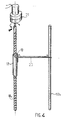
- FIG. 4 illustrates another embodiment of a system making it possible to introduce and extract the product inside the enclosure.
- the introduction (or extraction) of the product is also obtained by means of an assembly comprising two rods (10a, 10b) acting as slides, on which a support (20) can be moved. arranged below the base (8) of the pocket (4).
- the movement of the support (20) along the two rods (10a, 10b) is controlled according to the screw / nut principle.
- One of the rods (10a) is in the form of a threaded rod and can be rotated by means of an electric geared motor (21) with two directions of travel.
- the bearing (12) associated with the support plate (20) has the form of a nut.
- Such a set therefore allows the support plate (20) to be lowered and raised in a positive manner.
- the duration of immersion inside the enclosure can be programmed, for example by means of an electronic card controlling the action of the geared motor (21).
- Such an assembly of particularly simple design not only facilitates the operations of introduction and maintenance and removal of a bottle inside the coolant, but moreover, has a very high efficiency by the fact that the bag being made of a flexible material, it perfectly fits the periphery of the container (bottle) containing the product to be cooled.
Abstract
Description
La présente invention a trait à un perfectionnement apporté aux installations permettant de refroidir rapidement, voire même de congeler (ou inversement de réchauffer) des produits divers, notamment des liquides tels que des boissons stockées dans des bouteilles. Dans la suite de la description, l'invention sera décrite pour le traitement de liquides stockés dans des bouteilles, mais il est évident que cela n'est pas limitatif et que l'installation conforme à l'invention pourrait être utilisée pour des produits stockés sous d'autres formes (par exemple sous forme de sachets, boites métalliques ou en carton), voire même pour des produits solides.The present invention relates to an improvement made to installations making it possible to rapidly cool, or even to freeze (or conversely to reheat) various products, in particular liquids such as drinks stored in bottles. In the following description, the invention will be described for the treatment of liquids stored in bottles, but it is obvious that this is not limiting and that the installation according to the invention could be used for stored products in other forms (for example in the form of sachets, metal or cardboard boxes), or even for solid products.
Dans le domaine du refroidissement rapide de produits divers, il est bien connu que l'on obtient des meilleurs résultats en plongeant directement le produit à refroidir à l'intérieur du milieu, par exemple directement à l'intérieur d'une saumure très froide ou de glace fondante, et ce comme cela ressort notamment du WO-A88 03251 (correspondant à l'US-A-4 920 763) ou de l'US-A2 422 350.In the field of rapid cooling of various products, it is well known that better results are obtained by directly immersing the product to be cooled inside the medium, for example directly inside a very cold brine or melting ice, and this is apparent in particular from WO-A88 03251 (corresponding to US-A-4,920,763) or from US-A2,422,350.
Si une telle technique donne de bons résultats, il est évident que le contact entre le produit et le milieu refroidissant présente des inconvénients, notamment dans le cas de produits alimentaires. Par suite, il a été proposé depuis fort longtemps d'envelopper le produit à refroidir d'une pellicule mince de protection. Il n'en demeure pas moins, même avec une telle protection, notamment lorsque le fluide refroidissant est un liquide, qu'une telle solution ne donne pas entière satisfaction.If such a technique gives good results, it is obvious that the contact between the product and the cooling medium has drawbacks, especially in the case of food products. Consequently, it has been proposed for a very long time to wrap the product to be cooled with a thin protective film. The fact remains, even with such protection, especially when the cooling fluid is a liquid, that such a solution is not entirely satisfactory.
Pour obtenir un refroidissement rapide, il a également été proposé depuis fort longtemps, notamment dans le brevet US-2 061 427, d'utiliser des ensembles réfrigérants comportant des poches (ou similaires) qui plongent à l'intérieur du fluide réfrigérant et qui sont destinés à contenir des bouteilles renfermant le liquide à refroidir. De tels ensembles présentent comme avantage de permettre d'avoir un refroidissement rapide des bouteilles et d'éviter que leur surface ne soit mouillée par le fluide. Pour obtenir une bonne efficacité, il est cependant nécessaire d'avoir un bon contact entre la surface des bouteilles et l'enveloppe, ce qui implique donc soit d'utiliser toujours les mêmes bouteilles pour une enveloppe de forme donnée soit, comme décrit dans le document précité, d'avoir une enveloppe extensible (en caoutchouc), de structure relativement complexe puisque, pour avoir un bon échange thermique, cela implique de prévoir des inserts métalliques. En outre, même avec une telle enveloppe extensible, il est évident que l'on est limité dans la gamme de produits que l'on peut traiter et que l'enveloppe ne viendra pas plaquer correctement à la surface d'un objet ayant une forme autre que cylindrique. même si une telle enveloppe peut être agrandie grâce à l'extensibilité du matériau qui la compose, en revanche, elle ne s'appliquera pas contre la surface d'éléments dont les dimensions sont inférieures à son diamètre nominal. Enfin, la partie supérieure de la bouteille n'est pas en contact avec la paroi de l'enveloppe et sa mise en place et son enlèvement peut être délicat à réaliser, car elle doit être introduite "en force" si elle est d'un diamètre correspondant sensiblement au diamètre de l'enveloppe, alors que dans le cas de petites bouteilles, comme dit précédemment, l'enveloppe ne viendra pas plaquer contre la périphérie, et de plus cela impliquera d'effectuer la mise en place et le retrait de la bouteille manuellement en plongeant la main à l'intérieur de l'enveloppe.To obtain rapid cooling, it has also been proposed for a long time, in particular in US Pat. No. 2,061,427, to use refrigerating assemblies comprising pockets (or the like) which plunge inside the refrigerant and which are intended to contain bottles containing the liquid to be cooled. Such assemblies have the advantage of allowing rapid cooling of the bottles and of preventing their surface from being wetted by the fluid. To obtain good efficiency, it is however necessary to have good contact between the surface of the bottles and the envelope, which therefore implies either either always using the same bottles for an envelope of given shape or, as described in the aforementioned document, to have an expandable envelope (rubber), of relatively complex structure since, to have a good heat exchange, this involves providing metal inserts. In addition, even with such an extensible envelope, it is obvious that one is limited in the range of products that can be treated and that the envelope will not correctly press on the surface of an object having a shape. other than cylindrical. even if such an envelope can be enlarged thanks to the extensibility of the material which composes it, on the other hand, it will not be applied against the surface of elements whose dimensions are less than its nominal diameter. Finally, the upper part of the bottle is not in contact with the wall of the envelope and its installation and removal can be difficult to carry out, because it must be introduced "in force" if it is of a diameter corresponding substantially to the diameter of the envelope, while in the case of small bottles, as said above, the envelope will not press against the periphery, and moreover this will involve carrying out the establishment and removal of the bottle manually by plunging the hand inside the envelope.
L'invention permet, non seulement de résoudre les problèmes précités, mais permet également de résoudre un problème non posé ni résolu à ce jour qui est celui de pouvoir réaliser un ensemble permettant une durée d'échange thermique programmée, et ne demandant aucune surveillance de la part de l'utilisateur.The invention not only makes it possible to solve the aforementioned problems, but also makes it possible to solve a problem that has not yet been posed or resolved, which is that of being able to produce an assembly allowing a programmed heat exchange duration, and requiring no monitoring of from the user.
D'une manière générale, l'invention concerne donc un perfectionnement apporté aux installations permettant de réaliser un refroidissement rapide de produits divers stockés notamment à l'intérieur d'une bouteille du type constituées par un bac, disposé à l'intérieur d'une enceinte isolante, et qui contient un liquide maintenu à très basse température au moyen d'un circuit réfrigérant, le maintien à l'intérieur du milieu réfrigérant des produits à refroidir étant obtenu au moyen de "poches" qui plongent à l'intérieur du fluide réfrigérant et à l'intérieur desquelles sont disposés les produits à refroidir, et il se caractérise en ce que la (ou les) poche(s) se présente(nt) sous la forme d'une enveloppe ouverte à sa partie supérieure, à base d'un film plastique étanche souple, maintenue le long de leurs zone ouverte à la partie supérieure de l'enceinte, et dont la base fermée est associée à des moyens permettant de la déplacer depuis la partie supérieure ouverte jusqu'à proximité du fond de l'enceinte et inversement.In general, the invention therefore relates to an improvement made to installations making it possible to rapidly cool various products stored in particular inside a bottle of the type constituted by a tray, placed inside a insulating enclosure, and which contains a liquid maintained at very low temperature by means of a refrigerant circuit, the keeping inside the refrigerating medium of the products to be cooled being obtained by means of "pockets" which plunge inside the fluid refrigerant and inside which the products to be cooled are arranged, and it is characterized in that the bag (s) is (are) in the form of an envelope open at its upper part, based of a flexible waterproof plastic film, maintained along their open area at the upper part of the enclosure, and whose closed base is associated with means making it possible to move it from the upper part open open near the bottom of the enclosure and vice versa.
Grâce à un tel mode de réalisation, la mise en place et l'enlèvement des bouteilles à refroidir peut s'effectuer non seulement de manière très simple, puisque en position haute, la poche est repliée et n'ensère donc pas la bouteille, alors qu'en position immergée, elle vient plaquer parfaitement contre la périphérie de ladite bouteille.Thanks to such an embodiment, the installation and removal of the bottles to be cooled can be carried out not only in a very simple manner, since in the high position, the pocket is folded and therefore does not grip the bottle, then that in the submerged position, it presses perfectly against the periphery of said bottle.
De plus, selon un mode préférentiel de réalisation conforme à l'invention permettant de déplacer la poche à l'intérieur du liquide réfrigérant, il est également possible de l'associer à des moyens permettant de programmer la durée d'immersion, donc le refroidissement. Selon ce mode de réalisation préférentiel, les moyens de déplacement de la poche sont constitués par un ensemble de glissières le long desquelles coulisse un support disposé en-dessous de la surface inférieure de la poche. Ce support peut être associé à un flotteur, la mise en place du produit à l'intérieur de l'enceinte réfrigérante étant obtenue au moyen d'une poussée, et la remontée après maintien pendant une durée déterminée s'effectuant librement par le simple principe d'Archimède. Selon une variante préférentielle, une des glissières se présentera sous la forme d'une tige filetée passant à l'intérieur d'un palier en forme d'écrou associé au support, l'entraînement en rotation de la tige par l'intermédiaire d'un motoréducteur électrique permettant de faire descendre et monter ledit support de manière positive.In addition, according to a preferred embodiment in accordance with the invention making it possible to move the bag inside the coolant, it is also possible to associate it with means making it possible to program the duration of immersion, therefore cooling. . According to this preferred embodiment, the means for moving the pocket consist of a set of slides along which slides a support disposed below the lower surface of the pocket. This support can be associated with a float, the positioning of the product inside the refrigerating chamber being obtained by means of a push, and the ascent after maintenance for a determined period is carried out freely by the simple principle Archimedes. According to a preferred variant, one of the slides will be in the form of a threaded rod passing inside a bearing in the form of a nut associated with the support, the rotary drive of the rod by means of an electric gear motor making it possible to lower and mount said support positively.
L'invention et les avantages qu'elle apporte seront cependant mieux compris grâce à l'exemple de réalisation concret donné ci-après à titre indicatif mais non limitatif et qui est illustré par les schémas annexés dans lesquels :
- les figures 1 et 2 sont des vues schématiques en coupe et en élévation de l'ensemble d'une installation conforme à l'invention représentant d'une part, la bouteille en position de refroidissement (figure 1) et, d'autre part, la position de la bouteille lors de sa mise en place ou de son enlèvement (figure 2) ;
- la figure 3 est une vue schématique en élévation d'un mode de réalisation du système associé à la poche de maintien et qui permet de la déployer et de la remonter à l'intérieur de l'enceinte de réfrigération ;
- la figure 4 illustre un autre mode de réalisation d'un système associé à la poche de maintien, permettant de la déployer à l'intérieur de l'enceinte et de la remonter après un temps déterminé.
- FIGS. 1 and 2 are schematic sectional and elevation views of the assembly of an installation in accordance with the invention representing, on the one hand, the bottle in the cooling position (FIG. 1) and, on the other hand, the position of the bottle during its installation or removal (Figure 2);
- Figure 3 is a schematic elevational view of an embodiment of the system associated with the holding bag and which allows it to be deployed and reassembled inside the refrigeration chamber;
- FIG. 4 illustrates another embodiment of a system associated with the holding pocket, making it possible to deploy it inside the enclosure and to reassemble it after a determined time.
Si l'on se reporte aux schémas annexés et plus particulièrement aux figures 1 et 2, l'installation conforme à l'invention est constituée par un bac isothermique (1) doté d'un circuit réfrigérant (2) maintenant à très basse température un liquide (3), constitué d'une solution incongelable, telle que par exemple d'une saumure. A l'intérieur de ce bac (1), sont disposées des poches (une seule étant représentée par mesure de simplification), désignées par la référence générale (4) et qui sont destinées à recevoir des bouteilles (5) à refroidir. Conformément à l'invention, lesdites poches (4) sont constituées par un film de matière plastique étanche, tel que par exemple un film de polyéthylène, dont la partie supérieure (6) ouverte est fixée sur un couvercle (7). Lesdites poches (4) sont associées à des moyens permettant soit de rapprocher leur base (8) de l'ouverture (6) (figure 2), soit au contraire (figure 1), de déployer la poche (4) à l'intérieur de l'enceinte pour approcher la base (8) du fond (9) de ladite enceinte.If reference is made to the appended diagrams and more particularly to FIGS. 1 and 2, the installation according to the invention consists of an isothermal tank (1) provided with a refrigerant circuit (2) now at very low temperature a liquid (3), consisting of an unfrozen solution, such as for example a brine. Inside this tank (1), are arranged pockets (only one being shown for simplification), designated by the general reference (4) and which are intended to receive bottles (5) to be cooled. According to the invention, said pockets (4) consist of a waterproof plastic film, such as for example a polyethylene film, the open upper part (6) of which is fixed to a cover (7). Said pockets (4) are associated with means allowing either to bring their base (8) closer to the opening (6) (Figure 2), or on the contrary (Figure 1), to deploy the pocket (4) inside of the enclosure to approach the base (8) of the bottom (9) of said enclosure.
Dans la forme de réalisation illustrée aux figures 1 à 3, les ensembles dits "systèmes d'introduction" sonconstitués de deux tiges (10a,10b) (voir figure 3) faisant office de glissières et sur lesquelles peut coulisser un flotteur (11) monté sous un support (20) disposé en dessous de la base (8) de la poche (4). De préférence, le côté de l'ouverture (6) de la poche (5) est solidarisé du couvercle (7) au moyen d'une colerette (15), afin que la partie supérieure de ladite poche ne trempe pas dans le liquide de refroidissement (3) lors de l'immersion de la bouteille (5). Dans le mode de réalisation illustré aux figures 1 à 3, le support (20) est muni d'un flotteur (11) et peut coulisser le long des deux tiges ou glissières (10a,10b). L'un des paliers ((12) dans le cas présent) que comporte le support (20) et la tige ou glissière (10a) qui lui est associée, est conçu de manière à pouvoir assurer le blocage de l'ensemble à l'intérieur de l'enceinte ainsi que son déblocage lorsqu'on souhaite extraire la bouteille. Un tel système peut être constitué comme cela est illustré à la figure 3, par un verrou (13) qui peut venir s'encastrer dans des encoches (13a) le long de la tige (10a). Le blocage (et déblocage) est obtenu en provoquant une rotation de la tige (10a) par un moyen mécanique (14) (excentrique) actionné par un système d'électro-aimant ou un moteur électrique (15).In the embodiment illustrated in Figures 1 to 3, the so-called "introduction systems" are made up of two rods (10a, 10b) (see Figure 3) acting as slides and on which a float (11) mounted can slide under a support (20) disposed below the base (8) of the pocket (4). Preferably, the side of the opening (6) of the pocket (5) is secured to the cover (7) by means of a flange (15), so that the upper part of said pocket does not soak in the coolant (3 ) when the bottle (5) is immersed. In the embodiment illustrated in Figures 1 to 3, the support (20) is provided with a float (11) and can slide along the two rods or slides (10a, 10b). One of the bearings ((12) in the present case) that comprises the support (20) and the rod or slide (10a) which is associated with it, is designed so as to be able to block the assembly to the inside the enclosure and its release when you want to extract the bottle. Such a system can be constituted as illustrated in FIG. 3, by a lock (13) which can come to be embedded in notches (13a) along the rod (10a). Locking (and unlocking) is obtained by causing rotation of the rod (10a) by mechanical means (14) (eccentric) actuated by an electromagnet system or an electric motor (15).
Grâce à un tel ensemble, lors de l'introduction de la bouteille (figure 2), suivie d'une pression sur celle-ci, l'ensemble flotteur (11) + bouteille (5) s'enfonce donc dans le liquide réfrigérant (3). La poche plastique (4) se déplie donc et entoure la bouteille et non seulement la protège, mais également plaque parfaitement contre sa périphérie. Lorsque la bouteille est totalement immergée, le système de blocage (13) maintient le flotteur (11) en totale immersion. La bouteille (5) est maintenue immergée par le sac ou poche en plastique, dont le fond est relié au flotteur (11). La durée de l'immersion, donc le refroidissement, peut être commandée par une temporisation. Lorsque la durée choisie est écoulée, la temporisation actionne le système de blocage (13) par la rotation de la tige (10a), commandée par le système (14) mu par le moteur (15) alimenté temporairement par la temporisation. La glissière (12) se trouve alors désolidarisée de la tige (10a) et, par le simple principe d'Archimède, a tendance à remonter à la surface de liquide de refroidissement (3). Par suite, la bouteille remonte automatiquement en position haute (figure 2), n'est plus immergée dans le liquide de refroidissement (3) et son refroidissement est stoppé. Le système mécanique (14) commandé par le moteur (15) revient à sa position initiale, et le système de blocage (13) est à nouveau verrouillé pour une autre introduction.Thanks to such an assembly, during the introduction of the bottle (FIG. 2), followed by pressure on it, the float assembly (11) + bottle (5) therefore sinks into the coolant ( 3). The plastic pocket (4) therefore unfolds and surrounds the bottle and not only protects it, but also places it perfectly against its periphery. When the bottle is completely submerged, the locking system (13) keeps the float (11) in total immersion. The bottle (5) is kept submerged by the plastic bag or pocket, the bottom of which is connected to the float (11). The duration of the immersion, and therefore the cooling, can be controlled by a time delay. When the chosen duration has elapsed, the time delay activates the blocking system (13) by the rotation of the rod (10a), controlled by the system (14) driven by the motor (15) supplied temporarily by the time delay. The slide (12) is then separated from the rod (10a) and, by the simple principle of Archimedes, tends to rise to the surface of the coolant (3). As a result, the bottle rises automatically to the high position (Figure 2), is no longer immersed in the coolant (3) and its cooling is stopped. The mechanical system (14) controlled by the motor (15) returns to its initial position, and the blocking system (13) is again locked for another introduction.
Bien entendu, le volume du flotteur et ses caractéristiques seront fonction de sa nature ainsi que de la densité du liquide réfrigérant. Ce flotteur sera calculé de telle sorte que lorsqu'il est libéré, il puisse vaincre le poids de la bouteille (ou similaire) à extraire de l'immersion.Of course, the volume of the float and its characteristics will depend on its nature as well as the density of the coolant. This float will be calculated so that when it is released, it can overcome the weight of the bottle (or similar) to be extracted from the immersion.
La figure 4 illustre une autre forme de réalisation d'un système permettant d'introduire et d'extraire le produit à l'intérieur de l'enceinte. Par rapport au mode de réalisation décrit précédemment, l'introduction (ou extraction) du produit est également obtenue au moyen d'un ensemble comportant deux tiges (10a,10b) faisant office de glissières, sur lequel peut être déplacé un support (20) disposé en dessous de la base (8) de la poche (4). Dans ce mode de réalisation, la commande des déplacements du support (20) le long des deux tiges (10a,10b) est réalisée selon le principe vis/écrou. L'une des tiges (10a) se présente sous la forme d'une tige filetée et peut être entraînée en rotation par l'intermédiaire d'un motoréducteur électrique (21) à deux sens de marche. Le palier (12) associé à la plaque support (20) a quant à lui, la forme d'un écrou. Un tel ensemble permet donc de faire descendre et monter le plateau support (20) de manière positive. Par ailleurs, comme précédemment, la durée d'immersion à l'intérieur de l'enceinte peut être programmée, par exemple par l'intermédiaire d'une carte électronique commandant l'action du motoréducteur (21).FIG. 4 illustrates another embodiment of a system making it possible to introduce and extract the product inside the enclosure. Compared to the embodiment described above, the introduction (or extraction) of the product is also obtained by means of an assembly comprising two rods (10a, 10b) acting as slides, on which a support (20) can be moved. arranged below the base (8) of the pocket (4). In this embodiment, the movement of the support (20) along the two rods (10a, 10b) is controlled according to the screw / nut principle. One of the rods (10a) is in the form of a threaded rod and can be rotated by means of an electric geared motor (21) with two directions of travel. The bearing (12) associated with the support plate (20) has the form of a nut. Such a set therefore allows the support plate (20) to be lowered and raised in a positive manner. Furthermore, as before, the duration of immersion inside the enclosure can be programmed, for example by means of an electronic card controlling the action of the geared motor (21).
Un tel ensemble de conception particulièrement simple non seulement facilite les opérations d'introduction et de maintien et d'enlèvement d'une bouteille à l'intérieur du liquide réfrigérant, mais par ailleurs, présente une très grande efficacité par le fait que la poche étant en un matériau souple, elle vient épouser parfaitement la périphérie du récipient (bouteille) contenant le produit à refroidir.Such an assembly of particularly simple design not only facilitates the operations of introduction and maintenance and removal of a bottle inside the coolant, but moreover, has a very high efficiency by the fact that the bag being made of a flexible material, it perfectly fits the periphery of the container (bottle) containing the product to be cooled.
Claims (5)
Applications Claiming Priority (2)
| Application Number | Priority Date | Filing Date | Title |
|---|---|---|---|
| FR9004625A FR2660738B1 (en) | 1990-04-05 | 1990-04-05 | INSTALLATION FOR FAST REFRIGERATION (OR HEATING) OF PACKAGED PRODUCTS, ESPECIALLY BOTTLES. |
| FR9004625 | 1990-04-05 |
Publications (1)
| Publication Number | Publication Date |
|---|---|
| EP0451063A1 true EP0451063A1 (en) | 1991-10-09 |
Family
ID=9395645
Family Applications (1)
| Application Number | Title | Priority Date | Filing Date |
|---|---|---|---|
| EP91420104A Withdrawn EP0451063A1 (en) | 1990-04-05 | 1991-03-28 | Apparatus for quickly cooling packaged products, especially bottles |
Country Status (4)
| Country | Link |
|---|---|
| US (1) | US5237835A (en) |
| EP (1) | EP0451063A1 (en) |
| CA (1) | CA2038874A1 (en) |
| FR (1) | FR2660738B1 (en) |
Cited By (9)
| Publication number | Priority date | Publication date | Assignee | Title |
|---|---|---|---|---|
| US5698646A (en) * | 1993-04-30 | 1997-12-16 | Bridgestone Corporation | Process for producing elastomeric compound having reduced hysteresis |
| DE19924563A1 (en) * | 1999-05-28 | 2000-12-07 | Reisner Frank Und Partner Bera | Cooling equipment, comprises a heat insulated container with an inner chamber for the components to be cooled, a lid and a lifting unit. |
| WO2005015096A1 (en) * | 2003-08-08 | 2005-02-17 | Alberto Paradelo Borrajo | Bottle cooler |
| WO2009011666A1 (en) * | 2006-04-27 | 2009-01-22 | Mustafa Deniz Tokcan | Quick cooling method and system, especially for drinks |
| EP2119987A1 (en) * | 2008-05-14 | 2009-11-18 | Whirpool Corporation | Refrigerator provided with rapid cooling compartment for beverages |
| WO2010149402A1 (en) | 2009-06-25 | 2010-12-29 | Cambridge Design Research Llp | Dispensing apparatus and methods |
| WO2012090209A2 (en) * | 2010-12-29 | 2012-07-05 | Roike's Ideas Ltd. | Methods and devices of accelerated cooling |
| CN105402990A (en) * | 2014-05-30 | 2016-03-16 | 青岛海尔特种电冰柜有限公司 | Rapid cooling method of canned/bottled beverage rapid cooling machine |
| EP2218995A3 (en) * | 2009-02-13 | 2017-11-22 | BSH Hausgeräte GmbH | Cooling device with bottle cooling function |
Families Citing this family (46)
| Publication number | Priority date | Publication date | Assignee | Title |
|---|---|---|---|---|
| DE9305346U1 (en) * | 1993-04-08 | 1993-06-24 | Schaefer & Hof Apparatebau Gmbh, 3554 Lohra, De | |
| FR2707744B1 (en) * | 1993-07-13 | 1995-09-22 | Ardech Const Metall | Installation allowing the simultaneous cooling of liquids (drinks) in bottles, the production of fresh water and demoulded ice cubes which are automatically dispensed. |
| US5408845A (en) * | 1993-09-08 | 1995-04-25 | Microchill Int Ltd | Cooling or chilling apparatus |
| US5584187A (en) * | 1995-01-13 | 1996-12-17 | Whaley; Glenn E. | Quick-chill beverage chiller |
| AUPN056295A0 (en) * | 1995-01-17 | 1995-02-09 | Microchill International Limited | Chilling apparatus |
| DE29508881U1 (en) * | 1995-06-02 | 1995-08-03 | Nemeth Werner | Blast chiller for bottles, cans and the like |
| GB2303692A (en) * | 1995-06-15 | 1997-02-26 | Kula Products Limited | Rapid chilling system |
| US5797270A (en) * | 1997-04-21 | 1998-08-25 | Halterman; Carl | Rejuvenator chill device |
| US6351963B2 (en) | 2000-01-05 | 2002-03-05 | Jeffrey A. Surber | Refrigerated speed rail apparatus |
| EP1134000A3 (en) * | 2000-03-16 | 2004-11-10 | TuS Spezialkühlanlagen und Vertrieb GmbH | Device for fast freezing of blood plasma or food |
| JP3538378B2 (en) | 2000-10-27 | 2004-06-14 | 株式会社日立製作所 | Friction stir welding method |
| DE10261352A1 (en) * | 2002-11-11 | 2004-08-05 | BSH Bosch und Siemens Hausgeräte GmbH | Rapid cooling process and device |
| DE10261366A1 (en) * | 2002-12-30 | 2004-07-08 | BSH Bosch und Siemens Hausgeräte GmbH | Auxiliary cooling device |
| ES2222821B1 (en) * | 2003-07-28 | 2005-08-16 | Distribuciones Exclusivas Recor Sur, S.L. | COOLED DRINK DRINK EQUIPMENT. |
| EP1701120A1 (en) * | 2003-07-28 | 2006-09-13 | Distribuciones Exclusivas Recor Sur, S.L. | Device for cooling packaged drinks |
| US7977115B2 (en) | 2003-10-07 | 2011-07-12 | Winterlab Limited | Method for determining composition balance of cooled brine |
| US7415832B2 (en) * | 2003-10-07 | 2008-08-26 | Winterlab Limited | Method of freezing with brine |
| KR100713123B1 (en) | 2006-08-24 | 2007-05-02 | 위니아만도 주식회사 | Rack rail structure of wine storage |
| US20100218515A1 (en) * | 2007-08-27 | 2010-09-02 | Fink Harvey S | Chilling apparatus |
| US20090068330A1 (en) * | 2007-09-10 | 2009-03-12 | David Flynn Stancil | Method for cooling |
| DE102009000847A1 (en) * | 2009-02-13 | 2010-08-26 | BSH Bosch und Siemens Hausgeräte GmbH | Refrigerating appliance with bottle cooling function |
| US8161769B2 (en) * | 2009-04-07 | 2012-04-24 | Lauchnor John C | Refrigerated chest for rapidly quenching beverages and visually identifying when such beverages reach target temperature |
| GB2471865B (en) * | 2009-07-15 | 2011-06-29 | Bright Light Solar Ltd | Refrigeration apparatus |
| US8757434B2 (en) * | 2010-07-01 | 2014-06-24 | The Coca-Cola Company | Merchandiser |
| CN202393126U (en) * | 2011-08-25 | 2012-08-22 | 合肥美的荣事达电冰箱有限公司 | Refrigerator |
| GB2503191A (en) * | 2012-01-27 | 2013-12-25 | True Energy Ltd | Refrigeration apparatus comprising fluid reservoirs |
| CN108106295B (en) * | 2012-01-27 | 2020-12-04 | 确保冷藏有限公司 | Refrigeration device |
| CN102538340A (en) * | 2012-02-14 | 2012-07-04 | 合肥美的荣事达电冰箱有限公司 | Refrigerator and quick-freezing method thereof |
| US11852407B2 (en) | 2012-12-21 | 2023-12-26 | Blue Quench Llc | Device for altering temperature of beverage containers |
| US10174995B2 (en) | 2012-12-21 | 2019-01-08 | Blue Quench Llc | Modular retrofit quench unit |
| US11619436B2 (en) | 2019-04-08 | 2023-04-04 | Blue Quench Llc | Containers and methods and devices for enhancing thermal energy transfer between container contents and external environment |
| US8549871B1 (en) | 2012-12-21 | 2013-10-08 | John Lauchnor | Multi tray refrigerated chest for rapidly quenching beverages |
| US9200831B2 (en) | 2012-12-21 | 2015-12-01 | John Lauchnor | Refrigerated chest for rapidly quenching beverages |
| US9810473B2 (en) | 2012-12-21 | 2017-11-07 | Blue Quench Llc | Modular retrofit quench unit |
| GB201301494D0 (en) * | 2013-01-28 | 2013-03-13 | True Energy Ltd | Refrigeration apparatus |
| CN105556224B (en) | 2013-07-23 | 2019-10-11 | 确保冷藏有限公司 | Refrigerating plant and method |
| AU2015246707A1 (en) * | 2014-04-15 | 2016-12-01 | Sub Zero International Limited | Refrigeration apparatus |
| BR102014013038B1 (en) * | 2014-05-29 | 2022-07-26 | Ambev S/A | AUTOMATIC BEVERAGE REFRIGERATOR AND BEVERAGE COOLING METHOD |
| CN105444520A (en) * | 2014-05-30 | 2016-03-30 | 青岛海尔特种电冰柜有限公司 | Tin/bottle beverage rapid cooler |
| WO2016209980A1 (en) * | 2015-06-22 | 2016-12-29 | The Coca-Cola Company | Merchandiser with flexible temperature controlled columns |
| US20170030632A1 (en) * | 2015-07-31 | 2017-02-02 | Des Moines Supply Co. | Process and apparatus to super chill beer |
| US10704822B2 (en) | 2015-09-11 | 2020-07-07 | The Sure Chill Company Limited | Portable refrigeration apparatus |
| US10119774B1 (en) * | 2017-09-20 | 2018-11-06 | Umit Kosa | Instantaneous cooler/freezer using orbital shake method |
| MX2021011586A (en) | 2019-03-25 | 2021-10-13 | Pepsico Inc | Beverage container dispenser and method for dispensing beverage containers. |
| JP2022527339A (en) * | 2019-04-05 | 2022-06-01 | ペプシコ・インク | Condenser for beverage containers |
| US11910815B2 (en) | 2019-12-02 | 2024-02-27 | Pepsico, Inc. | Device and method for nucleation of a supercooled beverage |
Citations (9)
| Publication number | Priority date | Publication date | Assignee | Title |
|---|---|---|---|---|
| DE285521C (en) * | ||||
| US2061427A (en) * | 1935-08-16 | 1936-11-17 | Gen Motors Corp | Refrigerating apparatus |
| US2087117A (en) * | 1934-08-23 | 1937-07-13 | Arta Corp Of America | Sanitary butter container |
| US2422350A (en) * | 1944-08-05 | 1947-06-17 | Eshcol S Gross | Refrigerator port for dispensing container and closure therefor |
| US3782133A (en) * | 1972-08-14 | 1974-01-01 | Air Liquide | Low temperature storage vessel |
| US3843020A (en) * | 1973-08-16 | 1974-10-22 | W Bardeau | Automatic liquid dispensing apparatus |
| US4715195A (en) * | 1987-06-02 | 1987-12-29 | Iosif Kucza | Apparatus for rapid cooling of containers |
| WO1988003251A1 (en) * | 1986-10-23 | 1988-05-05 | Phillip Blake Provest | Chilling apparatus |
| EP0347286A1 (en) * | 1988-06-13 | 1989-12-20 | Sivin (S.A.R.L.) | Fast-cooling device and method for using this device |
Family Cites Families (5)
| Publication number | Priority date | Publication date | Assignee | Title |
|---|---|---|---|---|
| JPS54137147A (en) * | 1978-04-17 | 1979-10-24 | Mayekawa Mfg Co Ltd | Impregnate freezing device |
| FR2538885B1 (en) * | 1982-12-31 | 1985-07-05 | Air Liquide | PROCESS AND INSTALLATION FOR AT LEAST PARTIALLY COOLING A CONTAINER, PARTICULARLY FOR FREEZING THE NECK OF A BOTTLE OF INVERTED CHAMPAGNE |
| DE3430471C1 (en) * | 1984-08-18 | 1986-01-30 | C. Reichert Optische Werke Ag, Wien | Device for removing liquid nitrogen from a device for cryofixation and / or cryopreparation for the purpose of cryotransferring frozen samples |
| IL79109A (en) * | 1986-06-12 | 1992-08-18 | Baruch Indig | Porcelain furnace |
| KR960001161B1 (en) * | 1987-09-29 | 1996-01-19 | 도오교오 에레구토론 사가미 가부시끼가이샤 | Heat treatment apparatus |
-
1990
- 1990-04-05 FR FR9004625A patent/FR2660738B1/en not_active Expired - Fee Related
-
1991
- 1991-03-22 CA CA002038874A patent/CA2038874A1/en not_active Abandoned
- 1991-03-28 EP EP91420104A patent/EP0451063A1/en not_active Withdrawn
- 1991-04-02 US US07/679,112 patent/US5237835A/en not_active Expired - Fee Related
Patent Citations (9)
| Publication number | Priority date | Publication date | Assignee | Title |
|---|---|---|---|---|
| DE285521C (en) * | ||||
| US2087117A (en) * | 1934-08-23 | 1937-07-13 | Arta Corp Of America | Sanitary butter container |
| US2061427A (en) * | 1935-08-16 | 1936-11-17 | Gen Motors Corp | Refrigerating apparatus |
| US2422350A (en) * | 1944-08-05 | 1947-06-17 | Eshcol S Gross | Refrigerator port for dispensing container and closure therefor |
| US3782133A (en) * | 1972-08-14 | 1974-01-01 | Air Liquide | Low temperature storage vessel |
| US3843020A (en) * | 1973-08-16 | 1974-10-22 | W Bardeau | Automatic liquid dispensing apparatus |
| WO1988003251A1 (en) * | 1986-10-23 | 1988-05-05 | Phillip Blake Provest | Chilling apparatus |
| US4715195A (en) * | 1987-06-02 | 1987-12-29 | Iosif Kucza | Apparatus for rapid cooling of containers |
| EP0347286A1 (en) * | 1988-06-13 | 1989-12-20 | Sivin (S.A.R.L.) | Fast-cooling device and method for using this device |
Cited By (12)
| Publication number | Priority date | Publication date | Assignee | Title |
|---|---|---|---|---|
| US5698646A (en) * | 1993-04-30 | 1997-12-16 | Bridgestone Corporation | Process for producing elastomeric compound having reduced hysteresis |
| DE19924563A1 (en) * | 1999-05-28 | 2000-12-07 | Reisner Frank Und Partner Bera | Cooling equipment, comprises a heat insulated container with an inner chamber for the components to be cooled, a lid and a lifting unit. |
| WO2005015096A1 (en) * | 2003-08-08 | 2005-02-17 | Alberto Paradelo Borrajo | Bottle cooler |
| ES2224875A1 (en) * | 2003-08-08 | 2005-03-01 | Alberto Paradelo Borrajo | Bottle cooler |
| WO2009011666A1 (en) * | 2006-04-27 | 2009-01-22 | Mustafa Deniz Tokcan | Quick cooling method and system, especially for drinks |
| EP2119987A1 (en) * | 2008-05-14 | 2009-11-18 | Whirpool Corporation | Refrigerator provided with rapid cooling compartment for beverages |
| EP2218995A3 (en) * | 2009-02-13 | 2017-11-22 | BSH Hausgeräte GmbH | Cooling device with bottle cooling function |
| WO2010149402A1 (en) | 2009-06-25 | 2010-12-29 | Cambridge Design Research Llp | Dispensing apparatus and methods |
| WO2012090209A2 (en) * | 2010-12-29 | 2012-07-05 | Roike's Ideas Ltd. | Methods and devices of accelerated cooling |
| WO2012090209A3 (en) * | 2010-12-29 | 2013-03-28 | Roike's Ideas Ltd. | Methods and devices of accelerated cooling |
| CN105402990A (en) * | 2014-05-30 | 2016-03-16 | 青岛海尔特种电冰柜有限公司 | Rapid cooling method of canned/bottled beverage rapid cooling machine |
| CN105402990B (en) * | 2014-05-30 | 2018-04-06 | 青岛海尔特种电冰柜有限公司 | A kind of quickly cooling method of tank/bottle drink quick cooler |
Also Published As
| Publication number | Publication date |
|---|---|
| CA2038874A1 (en) | 1991-10-06 |
| FR2660738B1 (en) | 1994-10-28 |
| US5237835A (en) | 1993-08-24 |
| FR2660738A1 (en) | 1991-10-11 |
Similar Documents
| Publication | Publication Date | Title |
|---|---|---|
| EP0451063A1 (en) | Apparatus for quickly cooling packaged products, especially bottles | |
| EP0347286A1 (en) | Fast-cooling device and method for using this device | |
| FR2628077A1 (en) | CONTAINER FOR TRANSPORTING GRAFT | |
| FR2462352A1 (en) | ISOTHERMAL CONSERVATIVE CONTAINER FOR WINE BOTTLES AND SIMILAR OBJECTS | |
| BE1004012A3 (en) | Refresh device for liquids contained in containers. | |
| EP0230617A1 (en) | Apparatus for forming a melt of semiconductor material for growing a crystal element | |
| FR2759774A1 (en) | Device to heat and/or cool drinks esp. wine | |
| FR2586922A1 (en) | Steam cooker-mixer | |
| WO1997034264A1 (en) | Apparatus for dispensing refrigerating elements and said refrigerating elements | |
| EP0258092B1 (en) | Freezing apparatus for biological products packaged in straw, using a cryogenic liquid | |
| FR2508164A1 (en) | Maximum operating temp. permanent warning indicator for food freezer - uses ampoule contg. indicator substance of predetermined m.pt. | |
| FR2676532A1 (en) | Device for monitoring temperature in a freezing chamber | |
| EP0261007A1 (en) | Device for heating liquids by micro-waves, especially blood | |
| FR2563617A1 (en) | Process and device for keeping a bottle of wine at a predetermined temperature | |
| FR2491607A1 (en) | METHOD AND DEVICE FOR STORING LOW TEMPERATURE THERMAL ENERGY AND THEIR APPLICATION | |
| FR2747769A1 (en) | Compact integrated unit for producing fresh water and ice blocks | |
| EP0286481B1 (en) | Method and apparatus for fastening a metallic part to one side of an ophthalmic lens by moulding the part as molten metal | |
| FR2788677A1 (en) | Electric device for bringing drinks at temperature suitable for tasting has pump and tube allowing heat-exchanging fluid around drink receptacle, and probe and switch monitoring temperature of drink | |
| EP1435815B1 (en) | Cooking appliance with a vessel comprising a draining device with a thermal safety valve | |
| EP0755644A1 (en) | Thermally insulated or cooled container for magnetic treatment of foodstuff | |
| FR2613069A1 (en) | Device for controlling the level of refrigeration, in particular for refrigerated foodstuffs | |
| EP0017588A1 (en) | Electromagnetic device for the separation of inclusions contained in an electrically conductive fluid | |
| EP3714740B1 (en) | Appliance for preparing a brewed beverage provided with a device for moving a brewing basket with a mechanical basket return system | |
| EP2467661B1 (en) | Device for processing wet biomass by frying | |
| EP1668299B1 (en) | Disposable, self-cooling cup and device therefore |
Legal Events
| Date | Code | Title | Description |
|---|---|---|---|
| PUAI | Public reference made under article 153(3) epc to a published international application that has entered the european phase |
Free format text: ORIGINAL CODE: 0009012 |
|
| AK | Designated contracting states |
Kind code of ref document: A1 Designated state(s): CH DE ES FR GR IT LI |
|
| 17P | Request for examination filed |
Effective date: 19911223 |
|
| 17Q | First examination report despatched |
Effective date: 19930319 |
|
| STAA | Information on the status of an ep patent application or granted ep patent |
Free format text: STATUS: THE APPLICATION IS DEEMED TO BE WITHDRAWN |
|
| 18D | Application deemed to be withdrawn |
Effective date: 19940125 |